JP2010010058A - Electromagnet device - Google Patents
Electromagnet device Download PDFInfo
- Publication number
- JP2010010058A JP2010010058A JP2008170514A JP2008170514A JP2010010058A JP 2010010058 A JP2010010058 A JP 2010010058A JP 2008170514 A JP2008170514 A JP 2008170514A JP 2008170514 A JP2008170514 A JP 2008170514A JP 2010010058 A JP2010010058 A JP 2010010058A
- Authority
- JP
- Japan
- Prior art keywords
- iron core
- movable iron
- drive shaft
- coil
- movable
- Prior art date
- Legal status (The legal status is an assumption and is not a legal conclusion. Google has not performed a legal analysis and makes no representation as to the accuracy of the status listed.)
- Granted
Links
- XEEYBQQBJWHFJM-UHFFFAOYSA-N Iron Chemical group [Fe] XEEYBQQBJWHFJM-UHFFFAOYSA-N 0.000 claims abstract description 89
- 230000005284 excitation Effects 0.000 claims abstract description 5
- 230000002093 peripheral effect Effects 0.000 claims description 10
- 230000005347 demagnetization Effects 0.000 abstract description 2
- 229910052742 iron Inorganic materials 0.000 description 14
- 238000007789 sealing Methods 0.000 description 7
- 238000003466 welding Methods 0.000 description 7
- 230000004907 flux Effects 0.000 description 6
- 239000002184 metal Substances 0.000 description 5
- 229910052751 metal Inorganic materials 0.000 description 5
- WABPQHHGFIMREM-UHFFFAOYSA-N lead(0) Chemical compound [Pb] WABPQHHGFIMREM-UHFFFAOYSA-N 0.000 description 4
- 239000007789 gas Substances 0.000 description 3
- 238000003780 insertion Methods 0.000 description 3
- 230000037431 insertion Effects 0.000 description 3
- 239000000696 magnetic material Substances 0.000 description 3
- 239000011347 resin Substances 0.000 description 3
- 229920005989 resin Polymers 0.000 description 3
- 238000004804 winding Methods 0.000 description 3
- BGPVFRJUHWVFKM-UHFFFAOYSA-N N1=C2C=CC=CC2=[N+]([O-])C1(CC1)CCC21N=C1C=CC=CC1=[N+]2[O-] Chemical compound N1=C2C=CC=CC2=[N+]([O-])C1(CC1)CCC21N=C1C=CC=CC1=[N+]2[O-] BGPVFRJUHWVFKM-UHFFFAOYSA-N 0.000 description 2
- 210000000078 claw Anatomy 0.000 description 2
- 239000000463 material Substances 0.000 description 2
- NJPPVKZQTLUDBO-UHFFFAOYSA-N novaluron Chemical compound C1=C(Cl)C(OC(F)(F)C(OC(F)(F)F)F)=CC=C1NC(=O)NC(=O)C1=C(F)C=CC=C1F NJPPVKZQTLUDBO-UHFFFAOYSA-N 0.000 description 2
- 230000035939 shock Effects 0.000 description 2
- 230000002159 abnormal effect Effects 0.000 description 1
- 239000000853 adhesive Substances 0.000 description 1
- 230000001070 adhesive effect Effects 0.000 description 1
- 238000005219 brazing Methods 0.000 description 1
- 239000000919 ceramic Substances 0.000 description 1
- 238000001514 detection method Methods 0.000 description 1
- 230000000694 effects Effects 0.000 description 1
- 238000001125 extrusion Methods 0.000 description 1
- 239000011261 inert gas Substances 0.000 description 1
- 230000007257 malfunction Effects 0.000 description 1
- 230000013011 mating Effects 0.000 description 1
- 238000002844 melting Methods 0.000 description 1
- 230000008018 melting Effects 0.000 description 1
- 238000000034 method Methods 0.000 description 1
- 238000003825 pressing Methods 0.000 description 1
Images


Classifications
-
- H—ELECTRICITY
- H01—ELECTRIC ELEMENTS
- H01H—ELECTRIC SWITCHES; RELAYS; SELECTORS; EMERGENCY PROTECTIVE DEVICES
- H01H50/00—Details of electromagnetic relays
- H01H50/16—Magnetic circuit arrangements
- H01H50/18—Movable parts of magnetic circuits, e.g. armature
- H01H50/20—Movable parts of magnetic circuits, e.g. armature movable inside coil and substantially lengthwise with respect to axis thereof; movable coaxially with respect to coil
-
- H—ELECTRICITY
- H01—ELECTRIC ELEMENTS
- H01F—MAGNETS; INDUCTANCES; TRANSFORMERS; SELECTION OF MATERIALS FOR THEIR MAGNETIC PROPERTIES
- H01F7/00—Magnets
- H01F7/06—Electromagnets; Actuators including electromagnets
- H01F7/08—Electromagnets; Actuators including electromagnets with armatures
- H01F7/16—Rectilinearly-movable armatures
- H01F7/1607—Armatures entering the winding
- H01F7/1615—Armatures or stationary parts of magnetic circuit having permanent magnet
-
- H—ELECTRICITY
- H01—ELECTRIC ELEMENTS
- H01H—ELECTRIC SWITCHES; RELAYS; SELECTORS; EMERGENCY PROTECTIVE DEVICES
- H01H51/00—Electromagnetic relays
- H01H51/22—Polarised relays
- H01H51/2209—Polarised relays with rectilinearly movable armature
-
- H—ELECTRICITY
- H01—ELECTRIC ELEMENTS
- H01H—ELECTRIC SWITCHES; RELAYS; SELECTORS; EMERGENCY PROTECTIVE DEVICES
- H01H9/00—Details of switching devices, not covered by groups H01H1/00 - H01H7/00
- H01H9/30—Means for extinguishing or preventing arc between current-carrying parts
- H01H9/44—Means for extinguishing or preventing arc between current-carrying parts using blow-out magnet
- H01H9/443—Means for extinguishing or preventing arc between current-carrying parts using blow-out magnet using permanent magnets
-
- H—ELECTRICITY
- H01—ELECTRIC ELEMENTS
- H01F—MAGNETS; INDUCTANCES; TRANSFORMERS; SELECTION OF MATERIALS FOR THEIR MAGNETIC PROPERTIES
- H01F7/00—Magnets
- H01F7/06—Electromagnets; Actuators including electromagnets
- H01F7/08—Electromagnets; Actuators including electromagnets with armatures
- H01F7/081—Magnetic constructions
- H01F2007/083—External yoke surrounding the coil bobbin, e.g. made of bent magnetic sheet
-
- H—ELECTRICITY
- H01—ELECTRIC ELEMENTS
- H01H—ELECTRIC SWITCHES; RELAYS; SELECTORS; EMERGENCY PROTECTIVE DEVICES
- H01H50/00—Details of electromagnetic relays
- H01H50/02—Bases; Casings; Covers
- H01H50/023—Details concerning sealing, e.g. sealing casing with resin
- H01H2050/025—Details concerning sealing, e.g. sealing casing with resin containing inert or dielectric gasses, e.g. SF6, for arc prevention or arc extinction
-
- H—ELECTRICITY
- H01—ELECTRIC ELEMENTS
- H01H—ELECTRIC SWITCHES; RELAYS; SELECTORS; EMERGENCY PROTECTIVE DEVICES
- H01H51/00—Electromagnetic relays
- H01H51/22—Polarised relays
- H01H51/2209—Polarised relays with rectilinearly movable armature
- H01H2051/2218—Polarised relays with rectilinearly movable armature having at least one movable permanent magnet
-
- H—ELECTRICITY
- H01—ELECTRIC ELEMENTS
- H01H—ELECTRIC SWITCHES; RELAYS; SELECTORS; EMERGENCY PROTECTIVE DEVICES
- H01H50/00—Details of electromagnetic relays
- H01H50/54—Contact arrangements
- H01H50/546—Contact arrangements for contactors having bridging contacts
Abstract
Description
本発明は電磁石装置、特に、永久磁石を備えた有極電磁石装置に関する。 The present invention relates to an electromagnet device, and more particularly to a polarized electromagnet device provided with a permanent magnet.
従来、有極電磁石装置としては、所定方向に突出自在に保持された可動接極子と、前記可動接極子に対向配置された固定接極子と、前記可動接極子を突出方向に付勢する引外しばねと、前記引外しばねを蓄勢状態に保持する永久磁石と、前記可動接極子および前記固定接極子を通して前記永久磁石からの磁束の磁気経路を構成する継鉄と、異常電流の検知結果に基づいて、前記永久磁石による磁界に対する反磁界を形成する電磁石とを備え、前記可動接極子と前記固定接極子とが接極した時の接極面を通過する磁束密度が1テスラ以上であることを特徴とする釈放形電磁装置がある。
しかしながら、特許文献1の図1に示すように、前記有極電磁石装置はコイル用ボビン1の下端側に永久磁石5を配置してある。このため、動作時には前記永久磁石5の磁力に抗して可動接触子6をコイル2の磁力で駆動させる必要があり、消費電力が大きい。
また、釈放形電磁装置では、コイル2を巻回するためのスペースが少なく、コイル2で高い磁力を得ようとすると、装置が大型化するという問題点がある。
However, as shown in FIG. 1 of Patent Document 1, the polarized electromagnet device has a permanent magnet 5 arranged on the lower end side of the coil bobbin 1. For this reason, it is necessary to drive the movable contact 6 with the magnetic force of the coil 2 against the magnetic force of the permanent magnet 5 during operation, and the power consumption is large.
In addition, the release electromagnetic device has a problem that the space for winding the coil 2 is small, and if the coil 2 tries to obtain a high magnetic force, the device becomes large.
本発明は、前記問題点に鑑み、消費電力が少ない小型の有極電磁石装置を提供することを課題とする。 In view of the above problems, an object of the present invention is to provide a small polarized electromagnet device with low power consumption.
本発明にかかる有極電磁石装置は、前記課題を解決すべく、コイルを巻回したスプールの中心孔に駆動軸を軸心方向に往復移動可能に支持するとともに、前記駆動軸の下端部に可動鉄芯を同一軸心上に取り付け、前記コイルの励磁,消磁に基づいて往復移動する前記可動鉄芯で前記駆動軸を往復移動させる有極電磁石装置であって、前記可動鉄芯に永久磁石を同一軸心上に一体に設けた構成としてある。 In order to solve the above problems, the polarized electromagnet device according to the present invention supports the drive shaft in a center hole of a spool around which a coil is wound so that the drive shaft can reciprocate in the axial direction, and is movable at the lower end of the drive shaft. A polarized electromagnet device in which an iron core is mounted on the same axis, and the drive shaft is reciprocated by the movable iron core that reciprocates based on excitation and demagnetization of the coil, wherein a permanent magnet is attached to the movable iron core. The structure is provided integrally on the same axis.
本発明によれば、動作時に可動鉄芯に一体化した永久磁石がコイルの励磁によって発生した磁力に反発し、前記永久磁石を一体に設けた可動鉄芯が動作するので、従来例よりも動作電圧が低くなり、消費電力の少ない有極電磁石装置が得られる。
また、永久磁石が可動鉄芯に同一軸心上に一体に設けられるので、コイルの巻回スペースが従来例よりも大きくなる。このため、従来例と同一外形寸法のハウジングであっても、コイルをより多く巻回できるので、結果的により一層小型の有極電磁石装置が得られる。
According to the present invention, the permanent magnet integrated with the movable iron core during operation repels the magnetic force generated by the excitation of the coil, and the movable iron core integrally provided with the permanent magnet operates. A polarized electromagnet device with low voltage and low power consumption can be obtained.
Further, since the permanent magnet is integrally provided on the movable iron core on the same axis, the winding space of the coil becomes larger than that of the conventional example. For this reason, even if it is a housing of the same external dimension as a prior art example, since many coils can be wound, a much smaller polarized electromagnet apparatus is obtained as a result.
本発明にかかる実施形態としては、スプールの中心孔の内周面のうち、動作時にコイルの励磁で発生した磁力に基づく反発力を可動鉄芯に付与できる位置に、環状補助ヨークを配置しておいてもよい。
本実施形態によれば、動作時に、永久磁石に対する大きな反発力で可動鉄芯を駆動できるので、より一層消費電力が少ない有極電磁石装置が得られる。
As an embodiment according to the present invention, an annular auxiliary yoke is arranged at a position on the inner peripheral surface of the center hole of the spool at a position where a repulsive force based on the magnetic force generated by the excitation of the coil during operation can be applied to the movable iron core. It may be left.
According to the present embodiment, since the movable iron core can be driven with a large repulsive force against the permanent magnet during operation, a polarized electromagnet device with much lower power consumption can be obtained.
本発明にかかる他の実施形態としては、スプールの中心孔の内周面のうち、復帰時に可動鉄芯に設けた永久磁石の磁力に基づく前記可動鉄芯の復帰力を高める位置に、環状補助ヨークを配置しておいてもよい。
本実施形態によれば、環状補助ヨークにより、永久磁石の磁力を復帰力として効率的に活用できるので、俊敏な動作特性を有する有極電磁石装置が得られる。また、復帰完了後も前述の復帰力が維持されるので、外部からの衝撃力によっても誤動作しにくくなり、信頼性の高い有極電磁石装置が得られるという効果がある。
As another embodiment according to the present invention, an annular auxiliary member is provided at a position on the inner peripheral surface of the center hole of the spool to increase the return force of the movable iron core based on the magnetic force of the permanent magnet provided on the movable iron core at the time of return. A yoke may be arranged.
According to this embodiment, since the magnetic force of the permanent magnet can be efficiently used as the restoring force by the annular auxiliary yoke, a polarized electromagnet device having agile operating characteristics can be obtained. In addition, since the above-mentioned return force is maintained even after the return is completed, it is difficult to malfunction due to an impact force from the outside, and there is an effect that a highly reliable polarized electromagnet device can be obtained.
本発明にかかる実施形態を図1ないし図14の添付図面に従って説明する。
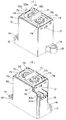
本発明にかかる有極電磁石装置の第1実施形態を適用したパワー負荷用電磁継電器は、図1ないし図11に示すように、大略、ケース10内に、上下で一体化された駆動機構ユニット20および接点機構ユニット50を収納するとともに、前記ケース10にカバー70を嵌合して被覆したものである。
Embodiments according to the present invention will be described with reference to the accompanying drawings of FIGS.
The power relay electromagnetic relay to which the first embodiment of the polarized electromagnet device according to the present invention is applied is generally a drive mechanism unit 20 integrated vertically in a
前記ケース10は、図4に示すように、後述する駆動機構ユニット20および接点機構ユニット50を収納可能な箱形状であり、その底面中央部に前記駆動機構ユニット20を位置決めするための嵌合用凹部11(図2および図3)を設けてある。また、前記ケース10は、対角線上に位置する外周角部の下方縁部から側方に台座部12,13を突設してある。前記台座部12,13には、取付孔14,14をそれぞれ形成してあるとともに、前記台座部12には端子台15を一体成形してある。さらに、前記ケース10は、開口縁部の隅部に、後述するリード線33aを引き出すためのスリット16を設けてあるとともに、対向する側壁の開口縁部に、後述するカバー70を抜け止めするための係合孔17を設けてある。
As shown in FIG. 4, the
駆動機構ユニット20は、図5ないし図7に示すように、断面略コ字形状の第1ヨーク21と、前記第1ヨークの両端部に架け渡した第2ヨーク22との間に、スプール31にコイル32を巻回した電磁石ブロック30を固定したものである。
As shown in FIGS. 5 to 7, the drive mechanism unit 20 includes a
第1ヨーク21は、図5に示すように、その底面中央に、後述する有底筒体34を挿通するための挿通孔21aを設けてあるとともに、その両端部に、第2ヨーク22を嵌合するための切り欠き部21bを形成してある。
As shown in FIG. 5, the
第2ヨーク22は、図10に示すように、その両端部を前記第1ヨーク21の切り欠き部21bにそれぞれ係合し、かつ、架け渡し可能な平面形状を有し、その中央部にカシメ孔22aを設けてある。また、前記第2ヨーク22は、その上面隅部に座ぐり孔22bを設けるとともに、前記座ぐり孔22bにガス封入パイプ23がロウ付けで気密接合されている。
As shown in FIG. 10, the
電磁石ブロック30は、図5に示すように、両端に鍔部31a,31bを有するスプール31にコイル32を巻回して形成したものであり、前記鍔部31aに設けた一対の中継端子33(奥側の中継端子は図示せず)に前記コイル32の引き出し線を絡げてハンダ付けしてある。さらに、前記中継端子33にはリード線33aを接続してある。また、図5および図6に示すように、前記スプール31の鍔部31a,31bを貫通する中心孔31cには有底筒体34が挿入される。前記有底筒体34の上方開口部は前記第2ヨーク22の下面にレーザー溶接で気密接合されている。そして、前記有底筒体34は、第1ヨーク21の挿通孔21aから突出する下端部に、環状補助ヨーク35を嵌合してある(図6)。
As shown in FIG. 5, the electromagnet block 30 is formed by winding a
本実施形態によれば、前記環状補助ヨーク35が前記有底筒体34と前記第1ヨーク21とに挟持される。このため、後述する可動鉄芯42の外周面と、前記第1ヨーク21および環状補助ヨーク35との対向面積が増大し、磁気抵抗が減少するので、磁気効率が向上し、消費電力を低減できるという利点がある。
According to the present embodiment, the annular
前記有底筒体34内には、図2に示すように、固定鉄芯40、復帰用コイルバネ41および可動鉄芯42が収納されている。そして、図6に示すように、前記固定鉄芯40は、その上端部を前記第2ヨーク22のカシメ孔22aにカシメ固定してある。このため、可動鉄芯42は前記復帰用コイルバネ41のバネ力で下方側に付勢される。さらに、前記有底筒体34は、図7に示すように、その底面と前記可動鉄芯42との間に、接着防止用金属シート48およびゴム製の衝撃緩衝用円板49を配置してある。
As shown in FIG. 2, a fixed
前記可動鉄芯42は、図6および図8に示すように、非磁性材からなる接続用パイプ43の内部に第1可動鉄片44を挿入する一方、前記接続用パイプ43の外周面にリング状永久磁石45および第2可動鉄片46を嵌合して一体化したものである。このため、前記接続用パイプ43は前記リング状永久磁石45の磁力を遮蔽することにより、所望の磁気回路を形成できる。また、前記第2可動鉄片46は、復帰時に、前記環状補助ヨーク35の開口縁部よりも上方に位置している。なお、図6および図7は、説明の便宜上、復帰用コイルバネ41を図示していない。
As shown in FIGS. 6 and 8, the
前記接点機構ユニット50は、図9に示すように、前記第2ヨーク22の上面にセラミック製封止容器51を接続一体化して形成した密閉空間内に、シールド部材55および可動接点ブロック60を配置したものである。
As shown in FIG. 9, the
前記封止容器51は、その天井面に設けた端子孔51a,51bに、座金51c,51cを介し、断面略T字形状の固定接点端子52,53をそれぞれロウ付けしてあるとともに、その下方開口縁部に接続用環状スカート部54をロウ付けしてある。前記固定接点端子52,53は、その上面にネジ孔52a,53aを設けてある一方、その下端面に固定接点52b,53bをそれぞれ設けてある。そして、前記環状スカート部54を前記第2ヨーク22の上面に位置決めし、レーザーで溶接一体化して前記密閉空間が形成される。
In the sealing
前記シールド部材55は、図10に示すように、中央に貫通孔56aを有する浅底の箱状樹脂成形品56に金属製シールド用リング57を嵌合し、前記箱状樹脂成形品56の底面に突設したカシメ用突起56bをカシメて一体化してある。前記金属製シールド用リング57は接点開閉時に生じたアークを引き寄せ、前記封止容器51と接続用環状スカート部54とのロウ付け部分が溶融することを防止するためのものである。
As shown in FIG. 10, the
可動接点ブロック60は、図10に示すように、両端部に可動接点62a,62bを形成した可動接触子62のカシメ孔62cに、駆動軸61の上端部を挿入し、座金63を介してカシメ固定してある。一方、前記駆動軸61に接圧用コイルバネ64を下方側から挿入し、前記駆動軸61の外周面に形成した環状溝部61aに、Eリング65を係合して組み付ける。このため、接圧用コイルバネ64を介して可動接触子62が上方に付勢されている。
As shown in FIG. 10, the
接圧用コイルバネ64は、可動接触子62に接点圧を付与するためのものである。このため、接圧用コイルバネ64を適宜選択することにより、吸引力特性の調整が可能となり、設計の自由度が広がるという利点がある。
The contact
前記カバー70は、図4に示すように、前記ケース10に嵌合可能な平面形状を有している。そして、前記カバー70は、図11に示すように、その内側面に平面略コ字形状の磁性材からなる保持部材90を嵌め込んである。
As shown in FIG. 4, the
前記カバー70は、その天井面の中央に突設した絶縁用突条71の両側に、端子孔72,73をそれぞれ設けてある。また、前記カバー70は、その天井面の隅部に図示しない外部端子のための回り止め用突起74をそれぞれ突設してあるとともに、その短辺側の両側側面から係合突起75をそれぞれ側方に突設してある。
The
前記保持部材90は、その対向する内側面の下方縁部から位置決め用爪部91を切り起こしてあるとともに、突き出し加工で位置決め用凹部92を形成してある。そして、前記位置決め用突起91を介して2枚の永久磁石93が相互に対向するように配置されている。前記永久磁石93は、可動接触子62と固定接点端子52,53との間に生じたアークを磁力で引っ張り、アークを消弧しやすくし、接点溶着を防止するとともに、封止容器51のロウ付け部分を保護する。
The holding
本実施形態にかかる封止接点装置の組立方法について説明する。
まず、第1ヨーク21に、スプール31にコイル32を巻回した電磁石ブロック30を載置して位置決めする。一方、固定鉄芯40を予めカシメ固定した第2ヨーク22の上面中央にシールド部材55を位置決めするとともに、可動接点ブロック60の駆動軸61を前記シールド部材55の貫通孔56aおよび固定鉄芯40の軸孔40aに挿入する。さらに、固定接点端子52,53および環状スカート部54をロウ付けした封止容器51の内周縁部を、前記シールド部材55のシールド用リング57に嵌合する。そして、前記封止容器51の開口縁部の下端面で箱状樹脂成形品56を押さえつつ、前記環状スカート部54を第2ヨーク22の上面にレーザー溶接して一体化する。
A method for assembling the sealed contact device according to the present embodiment will be described.
First, the electromagnet block 30 in which the
ついで、固定鉄芯40の下面から突出する駆動軸61を復帰用コイルバネ41および可動鉄芯42の軸孔42aに挿通する。そして、可動鉄芯42を復帰用コイルバネ41のバネ力に抗して固定鉄芯40に当接するまで押し込む。さらに、所定の接点圧を得られるまで駆動軸61を押し込み、可動接触子62が固定接点端子52,53の固定接点52a,53aに所定の接点圧力で接触した状態を維持し、可動鉄芯42に前記駆動軸61の下端部を溶接一体化する。ついで、ゴム製の衝撃緩衝用円板49および接着防止用金属シート48を順次収納した有底筒体34を、前記可動鉄芯42に被せ、その開口縁部を第2ヨーク22の下面にレーザー溶接で溶接一体化する。そして、ガス封入パイプ23から密閉空間内の空気を抜いた後、不活性ガスを注入し、前記ガス封入パイプ23をカシメて密封する。
Next, the
さらに、前記スプール31の中心孔31cに有底筒体34を挿入し、第2ヨーク22の両端部を第1ヨーク22の切り欠き部21bに嵌合し、カシメて固定する。そして、第1ヨーク21の挿通孔21aから突出する有底筒体34の下端部に環状補助ヨーク35を嵌合し、抜け止めする。
Further, the bottomed
そして、図4に示すように、上下に一体化した駆動機構ユニット20および接点機構ユニット50をベース10内に挿入する。さらに、突出する有底筒体34の下端部をベース10の凹部11に嵌合して位置決めするとともに、前記ベース10の切り欠き部16からリード線33aを引き出す。最後に、前記ベース10の係合孔17にカバー70の係合爪部75を係合して固定する。これにより、本実施形態にかかるパワー負荷用電磁継電器が得られる。
Then, as shown in FIG. 4, the drive mechanism unit 20 and the
本実施形態に係る接点装置の動作について説明する。
図2に示すように、コイル32に電圧が印加されていない場合には、復帰用コイルバネ41のバネ力および可動鉄芯42の永久磁石45の磁力より、可動鉄芯42が固定鉄芯40から開離している。このため、可動接触子62の両端部に位置する可動接点62a,62bが固定接点端子52,53の固定接点52b,53bから開離している。
The operation of the contact device according to this embodiment will be described.
As shown in FIG. 2, when no voltage is applied to the
そして、前記コイル32に電圧を印加すると、固定鉄芯40の可動鉄芯42に対する吸引力と、コイル32の磁束に対する可動鉄芯42のリング状永久磁石45の反発力との合力により、復帰用コイルバネ41のバネ力に抗して可動鉄芯42が固定鉄芯40側に移動する。このため、前記可動鉄芯42と一体な駆動軸61が軸心方向に移動し、可動接触子62の可動接点62a,62bが固定接点端子52,53の固定接点52b,53bに当接する。
When a voltage is applied to the
本実施形態によれば、動作時にリング状永久磁石45の磁力を有効活用できるので、少ない消費電力で可動鉄芯42を駆動できる。また、コイル32で発生した磁束が環状補助ヨーク35を通過でき、磁気効率が向上し、より大きな反発力が得られるので、消費電力がより一層少ない電磁継電器を得られる。
According to this embodiment, since the magnetic force of the ring-shaped
さらに、可動鉄芯42が固定鉄芯40側に吸引され、前記復帰用コイルバネ41のバネ力に抗して可動鉄芯42が移動し、接点圧を増大させる。ついで、前記復帰用コイルバネ41のバネ力に抗し、可動接触子62の可動接点62a,62bが固定接点端子52,53の固定接点52b,53bに所定の圧力で接触した後、可動鉄芯42が固定鉄芯40に吸着し、その状態を維持する。
Further, the
最後に、前記コイル32に対する電圧の印加を停止すると、コイル32の磁力が消失し、復帰用コイルバネ41のバネ力により、可動鉄芯42が固定鉄芯40から開離する。ついで、可動接触子62が固定接点端子52,53から開離した後、可動鉄芯42が元の位置に復帰する。復帰の際には、可動鉄芯42が接着防止用金属シート48を介して衝撃緩衝用円板49に衝突し、衝撃力が吸収,緩和される。
Finally, when the application of voltage to the
本実施形態によれば、復帰時に、リング状永久磁石45の磁束が環状補助ヨーク35を介して磁気回路を形成する。このため、復帰時においても前記リング状永久磁石45の磁力を有効に活用することにより、可動鉄芯42の復帰動作が俊敏になり、動作特性の優れた電磁継電器が得られるという利点がある。
According to the present embodiment, the magnetic flux of the ring-shaped
第2実施形態は、図12に示すように、前述の第1実施形態とほぼ同様であり、異なる点は可動鉄芯42の構造である。
すなわち、前記可動鉄芯42は、駆動軸61を挿入可能な内径の軸孔を有し、かつ、非磁性材からなる接続用パイプ43に、第1可動鉄片44、リング状永久磁石45および第2可動鉄片46を嵌合して一体化したものである。
As shown in FIG. 12, the second embodiment is substantially the same as the first embodiment described above, and the difference is the structure of the
That is, the
本実施形態によれば、リング状永久磁石45を第1可動鉄片44および第2可動鉄片46で直接挟持するように配置してあるので、組立精度が高く、動作特性にバラツキのない電磁継電器が得られるという利点がある。
他は前述の第1実施形態と同様であるので、同一部分に同一番号を附して説明を省略する。
According to the present embodiment, since the ring-shaped
Others are the same as those in the first embodiment described above, and thus the same parts are denoted by the same reference numerals and description thereof is omitted.
第3実施形態は、図13および図14に示すように、前述の第1実施形態とほぼ同様であり、異なる点は可動鉄芯42の構造である。
すなわち、前記可動鉄芯42は、非磁性材からなる接続用パイプ43の外周面に、第1可動鉄片44を嵌合する一方、その内部に駆動軸61を挿入可能な内径の軸孔を有するリング状永久磁石45および第2可動鉄片46を嵌合して一体化したものである。
As shown in FIG. 13 and FIG. 14, the third embodiment is substantially the same as the first embodiment described above, and the difference is the structure of the
That is, the
本実施形態によれば、可動鉄芯42の最外側面が第1可動鉄片44で覆われ、かつ、前記第1可動鉄片44が非磁性材からなる接続用パイプ43で遮蔽されている。このため、コイル32で発生した磁束が前記第1可動鉄片44を通過しやすくなり、磁気回路を形成できるので、大きな吸引力が得られ、磁気効率の高い電磁継電器が得られるという利点がある。
他は前述の第1実施形態と同様であるので、同一部分に同一番号を附して説明を省略する。
According to this embodiment, the outermost surface of the
Others are the same as those in the first embodiment described above, and thus the same parts are denoted by the same reference numerals and description thereof is omitted.
本発明にかかる有極電磁石装置は、前述の電磁継電器に限らず、他の電気機器にも適用できることは勿論である。 Of course, the polarized electromagnet device according to the present invention is not limited to the above-described electromagnetic relay but can be applied to other electric devices.
10:ケース
20:接点機構ユニット
30:電磁石ブロック
31:スプール
31c:中心孔
32:コイル
40:固定鉄芯
41:復帰用コイルバネ
42:可動鉄芯
43:接続用パイプ
44:第1可動鉄片
45:リング状永久磁石
46:第2可動鉄片
50:接点機構ユニット
52,53:固定接点端子
52b,53b:固定接点
50:接点機構ユニット
60:可動接点ブロック
61:駆動軸
62:可動接触子
62a,62b:可動接点
70:カバー
10: Case 20: Contact mechanism unit 30: Electromagnet block 31:
Claims (3)
前記可動鉄芯に永久磁石を同一軸心上に一体に設けたことを特徴とする有極電磁石装置。 A drive shaft is supported in the center hole of the spool around which the coil is wound so that the drive shaft can be reciprocated in the axial direction, and a movable iron core is attached to the lower end of the drive shaft on the same axis for exciting and demagnetizing the coil. A polarized electromagnet device that reciprocates the drive shaft with the movable iron core that reciprocates based on the following:
A polarized electromagnet apparatus, wherein a permanent magnet is integrally provided on the movable iron core on the same axis.
Priority Applications (4)
| Application Number | Priority Date | Filing Date | Title |
|---|---|---|---|
| JP2008170514A JP5163318B2 (en) | 2008-06-30 | 2008-06-30 | Electromagnet device |
| EP09163390.9A EP2141723B1 (en) | 2008-06-30 | 2009-06-22 | Electromagnet device |
| US12/489,936 US8179217B2 (en) | 2008-06-30 | 2009-06-23 | Electromagnet device |
| CN200910150317.2A CN101630567B (en) | 2008-06-30 | 2009-06-23 | Electromagnet device |
Applications Claiming Priority (1)
| Application Number | Priority Date | Filing Date | Title |
|---|---|---|---|
| JP2008170514A JP5163318B2 (en) | 2008-06-30 | 2008-06-30 | Electromagnet device |
Publications (2)
| Publication Number | Publication Date |
|---|---|
| JP2010010058A true JP2010010058A (en) | 2010-01-14 |
| JP5163318B2 JP5163318B2 (en) | 2013-03-13 |
Family
ID=41087368
Family Applications (1)
| Application Number | Title | Priority Date | Filing Date |
|---|---|---|---|
| JP2008170514A Active JP5163318B2 (en) | 2008-06-30 | 2008-06-30 | Electromagnet device |
Country Status (4)
| Country | Link |
|---|---|
| US (1) | US8179217B2 (en) |
| EP (1) | EP2141723B1 (en) |
| JP (1) | JP5163318B2 (en) |
| CN (1) | CN101630567B (en) |
Cited By (15)
| Publication number | Priority date | Publication date | Assignee | Title |
|---|---|---|---|---|
| WO2011090105A1 (en) | 2010-01-20 | 2011-07-28 | 株式会社エヌ・ティ・ティ・ドコモ | Mobile station device, channel information feedback method |
| WO2011115053A1 (en) * | 2010-03-15 | 2011-09-22 | オムロン株式会社 | Contact switching device |
| WO2011161919A1 (en) | 2010-06-21 | 2011-12-29 | Nissan Motor Co., Ltd. | Electromagnetic relay |
| WO2012029218A1 (en) * | 2010-08-31 | 2012-03-08 | 富士電機機器制御株式会社 | Electromagnetic switch |
| KR101163519B1 (en) | 2012-03-15 | 2012-07-06 | 주식회사 와이엠텍 | Contact device having bi-directional latch mechanism |
| WO2012157173A1 (en) * | 2011-05-19 | 2012-11-22 | 富士電機機器制御株式会社 | Electromagnetic contactor |
| WO2012165433A1 (en) * | 2011-05-31 | 2012-12-06 | オムロン株式会社 | Electromagnetic relay |
| KR101247122B1 (en) | 2011-09-15 | 2013-04-01 | 용성전기 주식회사 | electromagnetic contactor |
| US8860537B2 (en) | 2010-06-17 | 2014-10-14 | Nissan Motor Co., Ltd. | Electromagnetic relay |
| JPWO2015122151A1 (en) * | 2014-02-13 | 2017-03-30 | パナソニックIpマネジメント株式会社 | Electromagnetic relay |
| JP2017191868A (en) * | 2016-04-14 | 2017-10-19 | 株式会社デンソー | Electromagnetic actuator |
| DE102017112935A1 (en) | 2016-06-17 | 2017-12-21 | Panasonic Intellectual Property Management Co., Ltd. | Electromagnetic device and electromagnetic relay equipped with the electromagnetic device |
| DE102017113051A1 (en) | 2016-06-17 | 2017-12-28 | Panasonic Intellectual Property Management Co., Ltd. | Electromagnetic device and electromagnetic relay equipped with electromagnetic device |
| KR20180101553A (en) * | 2016-01-29 | 2018-09-12 | 에프코스 아게 | relay |
| JP2021532583A (en) * | 2018-07-23 | 2021-11-25 | ティーイー・コネクティビティ・コーポレイションTE Connectivity Corporation | Solenoid assembly with reduced release time |
Families Citing this family (79)
| Publication number | Priority date | Publication date | Assignee | Title |
|---|---|---|---|---|
| MX2011004330A (en) | 2008-10-27 | 2011-08-03 | Mueller Int Llc | Infrastructure monitoring system and method. |
| EP2433440B1 (en) | 2009-05-22 | 2018-07-25 | Mueller International, LLC | Infrastructure monitoring devices, systems, and methods |
| US8680956B2 (en) * | 2009-10-29 | 2014-03-25 | Mitsubishi Electric Corporation | Electromagnet device and switch device using electromagnet device |
| JP2011108452A (en) * | 2009-11-16 | 2011-06-02 | Fujitsu Component Ltd | Electromagnetic relay |
| KR101681591B1 (en) * | 2010-01-25 | 2016-12-01 | 엘에스산전 주식회사 | Electromagnetic switch |
| JP5573250B2 (en) * | 2010-03-09 | 2014-08-20 | オムロン株式会社 | Sealed contact device |
| WO2011159403A1 (en) | 2010-06-16 | 2011-12-22 | Mueller International, Llc | Infrastructure monitoring devices, systems, and methods |
| WO2012007802A1 (en) * | 2010-07-16 | 2012-01-19 | パナソニック電工株式会社 | Contact apparatus |
| KR20130124503A (en) * | 2010-11-01 | 2013-11-14 | 니뽄 도쿠슈 도교 가부시키가이샤 | Relay |
| JP5711044B2 (en) * | 2010-12-02 | 2015-04-30 | 富士電機株式会社 | Magnetic contactor, gas sealing method of magnetic contactor, and method of manufacturing magnetic contactor |
| JP4883232B1 (en) * | 2011-03-14 | 2012-02-22 | オムロン株式会社 | Electromagnetic relay |
| CN103339705B (en) * | 2011-03-14 | 2017-02-15 | 欧姆龙株式会社 | Electromagnetic relay |
| JP5085754B2 (en) * | 2011-03-14 | 2012-11-28 | オムロン株式会社 | Electromagnetic relay |
| JP5684650B2 (en) * | 2011-05-19 | 2015-03-18 | 富士電機株式会社 | Magnetic contactor |
| JP5689741B2 (en) * | 2011-05-19 | 2015-03-25 | 富士電機株式会社 | Magnetic contactor |
| JP5727862B2 (en) | 2011-05-19 | 2015-06-03 | 富士電機機器制御株式会社 | Magnetic contactor |
| JP5727861B2 (en) * | 2011-05-19 | 2015-06-03 | 富士電機機器制御株式会社 | Magnetic contactor |
| JP2012243590A (en) * | 2011-05-19 | 2012-12-10 | Fuji Electric Fa Components & Systems Co Ltd | Electromagnetic contactor |
| US8833390B2 (en) | 2011-05-31 | 2014-09-16 | Mueller International, Llc | Valve meter assembly and method |
| JP6025414B2 (en) * | 2011-09-30 | 2016-11-16 | 富士通コンポーネント株式会社 | Electromagnetic relay |
| JP5856426B2 (en) * | 2011-10-07 | 2016-02-09 | 富士電機株式会社 | Contact device and electromagnetic contactor using the same |
| US8855569B2 (en) | 2011-10-27 | 2014-10-07 | Mueller International, Llc | Systems and methods for dynamic squelching in radio frequency devices |
| JP5876270B2 (en) * | 2011-11-01 | 2016-03-02 | 富士電機株式会社 | Magnetic contactor |
| DE202011052220U1 (en) * | 2011-12-07 | 2013-03-11 | Eto Magnetic Gmbh | Bistable electromagnetic actuator and camshaft actuator |
| DE102012202084A1 (en) * | 2012-02-13 | 2013-08-14 | Siemens Aktiengesellschaft | Hinged armature bearing for magnetic release |
| JP5965218B2 (en) | 2012-06-08 | 2016-08-03 | 富士電機機器制御株式会社 | Magnetic contactor |
| KR101354806B1 (en) | 2012-06-14 | 2014-01-23 | 엘에스산전 주식회사 | Electromagnetic switching device |
| JP5938745B2 (en) * | 2012-07-06 | 2016-06-22 | パナソニックIpマネジメント株式会社 | Contact device and electromagnetic relay equipped with the contact device |
| EP2889892B1 (en) * | 2012-08-23 | 2017-02-01 | Panasonic Intellectual Property Management Co., Ltd. | Contact device |
| KR20140033814A (en) * | 2012-09-10 | 2014-03-19 | 엘에스산전 주식회사 | Electromagnetic switching device |
| CN102956406B (en) * | 2012-11-13 | 2015-03-11 | 上海金岩电器制造有限公司 | Straight-pulling type magnetic latching relay |
| JP6043173B2 (en) * | 2012-12-07 | 2016-12-14 | 富士通コンポーネント株式会社 | Electromagnetic relay |
| JP6064223B2 (en) * | 2012-12-28 | 2017-01-25 | パナソニックIpマネジメント株式会社 | Contact device and electromagnetic relay equipped with the contact device |
| KR101422394B1 (en) * | 2013-02-18 | 2014-07-22 | 엘에스산전 주식회사 | Electro magnetic switching device |
| KR101398720B1 (en) * | 2013-02-18 | 2014-05-27 | 엘에스산전 주식회사 | Electromagnetic switching device |
| DE202013102019U1 (en) * | 2013-05-08 | 2014-08-11 | Eto Magnetic Gmbh | Electromagnetic actuator |
| US9390875B2 (en) * | 2013-05-29 | 2016-07-12 | Active Signal Technologies, Inc. | Electromagnetic opposing field actuators |
| DE102013013585B4 (en) * | 2013-06-20 | 2020-09-17 | Rhefor Gbr | Self-holding magnet with particularly low electrical tripping power |
| WO2014208098A1 (en) * | 2013-06-28 | 2014-12-31 | パナソニックIpマネジメント株式会社 | Contact point device and electromagnetic relay mounted with same |
| DE102013010833A1 (en) * | 2013-06-28 | 2014-12-31 | Hydac Electronic Gmbh | Electromagnetic actuator |
| JP6265657B2 (en) * | 2013-08-26 | 2018-01-24 | 富士通コンポーネント株式会社 | Electromagnetic relay |
| JP6202943B2 (en) * | 2013-08-26 | 2017-09-27 | 富士通コンポーネント株式会社 | Electromagnetic relay |
| GB2520572A (en) | 2013-11-26 | 2015-05-27 | Johnson Electric Sa | Electrical Contactor |
| JP6312021B2 (en) | 2014-01-30 | 2018-04-18 | パナソニックIpマネジメント株式会社 | Remote control relay |
| KR101519784B1 (en) * | 2014-04-18 | 2015-05-12 | 현대자동차주식회사 | Battery relay for automobile |
| US9494249B2 (en) | 2014-05-09 | 2016-11-15 | Mueller International, Llc | Mechanical stop for actuator and orifice |
| US9565620B2 (en) | 2014-09-02 | 2017-02-07 | Mueller International, Llc | Dynamic routing in a mesh network |
| JP6287727B2 (en) * | 2014-09-25 | 2018-03-07 | アンデン株式会社 | Electromagnetic relay |
| KR101626365B1 (en) * | 2014-09-30 | 2016-06-01 | 엘에스산전 주식회사 | Actuator for circuit breaker and method for manufacturing the same |
| US10199192B2 (en) | 2014-12-30 | 2019-02-05 | Littlefuse, Inc. | Bi-stable electrical solenoid switch |
| JP6528271B2 (en) * | 2015-04-13 | 2019-06-12 | パナソニックIpマネジメント株式会社 | Contact device and electromagnetic relay |
| KR101943363B1 (en) * | 2015-04-13 | 2019-04-17 | 엘에스산전 주식회사 | Magnetic Switch |
| KR101943364B1 (en) * | 2015-04-23 | 2019-04-17 | 엘에스산전 주식회사 | Magnetic Switch |
| US9916952B2 (en) * | 2015-06-12 | 2018-03-13 | Te Connectivity Corporation | Carrier sub-assembly for an electrical relay device |
| US9865419B2 (en) * | 2015-06-12 | 2018-01-09 | Te Connectivity Corporation | Pressure-controlled electrical relay device |
| JP6558571B2 (en) * | 2015-07-01 | 2019-08-14 | パナソニックIpマネジメント株式会社 | Electromagnetic relay |
| DE102015212801A1 (en) * | 2015-07-08 | 2017-01-12 | Te Connectivity Germany Gmbh | Electrical switching arrangement with improved linear storage |
| KR101943365B1 (en) * | 2015-10-14 | 2019-01-29 | 엘에스산전 주식회사 | Direct Relay |
| JP6536472B2 (en) * | 2016-04-28 | 2019-07-03 | 株式会社デンソー | solenoid |
| JP6836241B2 (en) * | 2016-12-27 | 2021-02-24 | 富士通コンポーネント株式会社 | Electromagnetic relay |
| CH713442B1 (en) * | 2017-02-08 | 2021-03-31 | Elesta Gmbh Ostfildern De Zweigniederlassung Bad Ragaz | Relay. |
| JP6377791B1 (en) * | 2017-03-10 | 2018-08-22 | Emデバイス株式会社 | Electromagnetic relay |
| US10178617B2 (en) | 2017-05-01 | 2019-01-08 | Mueller International, Llc | Hail and acceptance for battery-powered devices |
| KR101891480B1 (en) * | 2017-10-12 | 2018-09-28 | 한국기초과학지원연구원 | Bobbin and Coil Assembly and Electromagnet Equipment including thereof |
| DE102017220503B3 (en) * | 2017-11-16 | 2019-01-17 | Te Connectivity Germany Gmbh | Double interrupting switch |
| DE102018120987A1 (en) * | 2018-08-28 | 2020-03-05 | Tdk Electronics Ag | Switching device |
| EP3617494A1 (en) * | 2018-08-28 | 2020-03-04 | Mahle International GmbH | Electromagnetic switch for a starting device |
| EP3845617B1 (en) | 2018-08-29 | 2022-10-05 | Nitto Kasei Co., Ltd. | Anti-fouling coating material composition |
| JP7103091B2 (en) * | 2018-09-07 | 2022-07-20 | オムロン株式会社 | relay |
| KR102427376B1 (en) * | 2018-10-25 | 2022-07-29 | 미쓰비시덴키 가부시키가이샤 | Electromagnets, electromagnetic switchgear, and manufacturing method of electromagnets |
| JP1637320S (en) * | 2018-11-12 | 2020-07-20 | ||
| JP7036047B2 (en) * | 2019-01-18 | 2022-03-15 | オムロン株式会社 | relay |
| KR102339179B1 (en) * | 2019-07-11 | 2021-12-14 | 엘에스일렉트릭 (주) | Arc path forming part and direct current relay include the same |
| JP7351155B2 (en) * | 2019-09-13 | 2023-09-27 | オムロン株式会社 | electromagnetic relay |
| JP7380175B2 (en) | 2019-12-19 | 2023-11-15 | オムロン株式会社 | electromagnetic relay |
| JP7067580B2 (en) * | 2020-03-18 | 2022-05-16 | 株式会社デンソーエレクトロニクス | Electromagnetic relay and manufacturing method of electromagnetic relay |
| CN114597097A (en) * | 2020-12-03 | 2022-06-07 | 华为技术有限公司 | Relay |
| JP2022141414A (en) * | 2021-03-15 | 2022-09-29 | オムロン株式会社 | electromagnetic relay |
| USD988274S1 (en) * | 2021-06-21 | 2023-06-06 | Ls Electric Co., Ltd. | Relay for electric automobile |
Citations (4)
| Publication number | Priority date | Publication date | Assignee | Title |
|---|---|---|---|---|
| JPS5581913U (en) * | 1978-11-30 | 1980-06-05 | ||
| JPS57198611A (en) * | 1981-05-30 | 1982-12-06 | Matsushita Electric Works Ltd | Electromagnetic driving device |
| JPS5852259U (en) * | 1981-10-06 | 1983-04-08 | 日立金属株式会社 | Actuator for door lock |
| JP2003197082A (en) * | 2001-12-25 | 2003-07-11 | Matsushita Electric Works Ltd | Sealed contact device |
Family Cites Families (23)
| Publication number | Priority date | Publication date | Assignee | Title |
|---|---|---|---|---|
| JPS53156056U (en) * | 1977-05-13 | 1978-12-07 | ||
| AU569879B2 (en) * | 1984-03-05 | 1988-02-25 | Mitsubishi Mining & Cement Co., Ltd. | Electromagnetic actuator apparatus |
| FR2606927B1 (en) * | 1986-11-19 | 1991-09-13 | Telemecanique Electrique | BISTABLE POLARIZED ELECTROMAGNET |
| US4737750A (en) * | 1986-12-22 | 1988-04-12 | Hamilton Standard Controls, Inc. | Bistable electrical contactor arrangement |
| EP0587611B1 (en) * | 1991-03-28 | 1997-05-21 | Kilovac Corporation | Dc relay device |
| JP3321963B2 (en) * | 1994-02-22 | 2002-09-09 | 株式会社デンソー | Plunger type electromagnetic relay |
| US5734310A (en) | 1995-08-09 | 1998-03-31 | Borg-Warner Automotive, Inc. | Magnetic latching solenoid assembly |
| US5892194A (en) * | 1996-03-26 | 1999-04-06 | Matsushita Electric Works, Ltd. | Sealed contact device with contact gap adjustment capability |
| DE19744396A1 (en) | 1997-10-08 | 1999-04-15 | Heinrich Kissling Gmbh & Co Kg | Bistable relay for heavy current range |
| JP3629362B2 (en) * | 1998-03-04 | 2005-03-16 | 愛三工業株式会社 | Driving method of electromagnetic valve for driving engine valve |
| CN2406328Y (en) * | 2000-02-29 | 2000-11-15 | 肖建华 | Permanent magnetic operation mechanism |
| JP3925091B2 (en) * | 2001-02-28 | 2007-06-06 | 株式会社豊田自動織機 | Control valve for variable capacity compressor and method for adjusting the control valve |
| US6512435B2 (en) * | 2001-04-25 | 2003-01-28 | Charles Willard | Bistable electro-magnetic mechanical actuator |
| JP4078820B2 (en) * | 2001-09-21 | 2008-04-23 | オムロン株式会社 | Sealed contact device |
| CN1248272C (en) * | 2001-11-29 | 2006-03-29 | 松下电工株式会社 | Electromagnetic switching apparatus |
| CN2631021Y (en) * | 2003-07-02 | 2004-08-04 | 吴经奋 | Bistable permanent-magnet mechanism |
| JP2005026182A (en) * | 2003-07-02 | 2005-01-27 | Matsushita Electric Works Ltd | Electromagnetic switching device |
| FR2880466B1 (en) * | 2004-12-30 | 2007-02-09 | Areva T & D Sa | BISTABLE ELECTROMAGNETIC ACTUATOR |
| CA2569064C (en) * | 2005-03-28 | 2011-08-02 | Matsushita Electric Works, Ltd. | Contact device |
| JP4910663B2 (en) | 2006-02-27 | 2012-04-04 | 富士電機機器制御株式会社 | Release electromagnetic device |
| JP4765761B2 (en) * | 2006-05-12 | 2011-09-07 | オムロン株式会社 | Electromagnetic relay |
| US7852178B2 (en) * | 2006-11-28 | 2010-12-14 | Tyco Electronics Corporation | Hermetically sealed electromechanical relay |
| US7868720B2 (en) * | 2007-11-01 | 2011-01-11 | Tyco Electronics Corporation India | Hermetically sealed relay |
-
2008
- 2008-06-30 JP JP2008170514A patent/JP5163318B2/en active Active
-
2009
- 2009-06-22 EP EP09163390.9A patent/EP2141723B1/en active Active
- 2009-06-23 US US12/489,936 patent/US8179217B2/en active Active
- 2009-06-23 CN CN200910150317.2A patent/CN101630567B/en active Active
Patent Citations (4)
| Publication number | Priority date | Publication date | Assignee | Title |
|---|---|---|---|---|
| JPS5581913U (en) * | 1978-11-30 | 1980-06-05 | ||
| JPS57198611A (en) * | 1981-05-30 | 1982-12-06 | Matsushita Electric Works Ltd | Electromagnetic driving device |
| JPS5852259U (en) * | 1981-10-06 | 1983-04-08 | 日立金属株式会社 | Actuator for door lock |
| JP2003197082A (en) * | 2001-12-25 | 2003-07-11 | Matsushita Electric Works Ltd | Sealed contact device |
Cited By (38)
| Publication number | Priority date | Publication date | Assignee | Title |
|---|---|---|---|---|
| WO2011090105A1 (en) | 2010-01-20 | 2011-07-28 | 株式会社エヌ・ティ・ティ・ドコモ | Mobile station device, channel information feedback method |
| WO2011115053A1 (en) * | 2010-03-15 | 2011-09-22 | オムロン株式会社 | Contact switching device |
| WO2011115049A1 (en) * | 2010-03-15 | 2011-09-22 | オムロン株式会社 | Contact switching device |
| KR101387386B1 (en) | 2010-03-15 | 2014-04-21 | 오므론 가부시키가이샤 | Contact switching device |
| JP5360291B2 (en) * | 2010-03-15 | 2013-12-04 | オムロン株式会社 | Contact switchgear |
| JP5310936B2 (en) * | 2010-03-15 | 2013-10-09 | オムロン株式会社 | Contact switchgear |
| US8860537B2 (en) | 2010-06-17 | 2014-10-14 | Nissan Motor Co., Ltd. | Electromagnetic relay |
| US8552823B2 (en) | 2010-06-21 | 2013-10-08 | Nissan Motor Co., Ltd. | Electromagnetic relay |
| JP2012028310A (en) * | 2010-06-21 | 2012-02-09 | Nissan Motor Co Ltd | Electromagnetic relay |
| WO2011161919A1 (en) | 2010-06-21 | 2011-12-29 | Nissan Motor Co., Ltd. | Electromagnetic relay |
| US8937518B2 (en) | 2010-08-31 | 2015-01-20 | Fuji Electric Co., Ltd. | Electromagnetic switch |
| JP2012054047A (en) * | 2010-08-31 | 2012-03-15 | Fuji Electric Fa Components & Systems Co Ltd | Electromagnetic switch |
| WO2012029218A1 (en) * | 2010-08-31 | 2012-03-08 | 富士電機機器制御株式会社 | Electromagnetic switch |
| WO2012157173A1 (en) * | 2011-05-19 | 2012-11-22 | 富士電機機器制御株式会社 | Electromagnetic contactor |
| JP2012243589A (en) * | 2011-05-19 | 2012-12-10 | Fuji Electric Fa Components & Systems Co Ltd | Electromagnetic contactor |
| US8823472B2 (en) | 2011-05-19 | 2014-09-02 | Fuji Electric Co., Ltd. | Electromagnetic contactor |
| WO2012165433A1 (en) * | 2011-05-31 | 2012-12-06 | オムロン株式会社 | Electromagnetic relay |
| JPWO2012165433A1 (en) * | 2011-05-31 | 2015-02-23 | オムロン株式会社 | Electromagnetic relay |
| KR101533002B1 (en) * | 2011-05-31 | 2015-07-01 | 오므론 가부시키가이샤 | Electromagnetic relay |
| US9324524B2 (en) | 2011-05-31 | 2016-04-26 | Omron Corporation | Electromagnetic relay |
| KR101247122B1 (en) | 2011-09-15 | 2013-04-01 | 용성전기 주식회사 | electromagnetic contactor |
| KR101163519B1 (en) | 2012-03-15 | 2012-07-06 | 주식회사 와이엠텍 | Contact device having bi-directional latch mechanism |
| JPWO2015122151A1 (en) * | 2014-02-13 | 2017-03-30 | パナソニックIpマネジメント株式会社 | Electromagnetic relay |
| US9734972B2 (en) | 2014-02-13 | 2017-08-15 | Panasonic Intellectual Property Management Co., Ltd. | Electromagnetic relay |
| KR102156992B1 (en) * | 2016-01-29 | 2020-09-21 | 티디케이 일렉트로닉스 아게 | relay |
| US10854406B2 (en) | 2016-01-29 | 2020-12-01 | Epcos Ag | Relay |
| KR20180101553A (en) * | 2016-01-29 | 2018-09-12 | 에프코스 아게 | relay |
| JP2019503056A (en) * | 2016-01-29 | 2019-01-31 | ティーディーケイ・エレクトロニクス・アクチェンゲゼルシャフトTdk Electronics Ag | relay |
| CN107299845A (en) * | 2016-04-14 | 2017-10-27 | 株式会社电装 | Electromagnetic actuators |
| JP2017191868A (en) * | 2016-04-14 | 2017-10-19 | 株式会社デンソー | Electromagnetic actuator |
| US10446349B2 (en) | 2016-06-17 | 2019-10-15 | Panasonic Intellectual Property Management Co., Ltd. | Electromagnetic device and electromagnetic relay equipped with electromagnetic device |
| US10446350B2 (en) | 2016-06-17 | 2019-10-15 | Panasonic Intellectual Property Management Co., Ltd. | Electromagnetic device and electromagnetic relay equipped with electromagnetic device |
| DE102017113051A1 (en) | 2016-06-17 | 2017-12-28 | Panasonic Intellectual Property Management Co., Ltd. | Electromagnetic device and electromagnetic relay equipped with electromagnetic device |
| DE102017112935A1 (en) | 2016-06-17 | 2017-12-21 | Panasonic Intellectual Property Management Co., Ltd. | Electromagnetic device and electromagnetic relay equipped with the electromagnetic device |
| US11227736B2 (en) | 2016-06-17 | 2022-01-18 | Panasonic Intellectual Property Management Co., Ltd. | Electromagnetic device and electromagnetic relay equipped with electromagnetic device |
| US11276539B2 (en) | 2016-06-17 | 2022-03-15 | Panasonic Intellectual Property Management Co., Ltd. | Electromagnetic device and electromagnetic relay equipped with electromagnetic device |
| JP2021532583A (en) * | 2018-07-23 | 2021-11-25 | ティーイー・コネクティビティ・コーポレイションTE Connectivity Corporation | Solenoid assembly with reduced release time |
| JP7374173B2 (en) | 2018-07-23 | 2023-11-06 | ティーイー・コネクティビティ・コーポレイション | Solenoid assembly with reduced release time |
Also Published As
| Publication number | Publication date |
|---|---|
| US20090322453A1 (en) | 2009-12-31 |
| EP2141723B1 (en) | 2017-03-15 |
| EP2141723A2 (en) | 2010-01-06 |
| CN101630567A (en) | 2010-01-20 |
| US8179217B2 (en) | 2012-05-15 |
| EP2141723A3 (en) | 2011-08-10 |
| JP5163318B2 (en) | 2013-03-13 |
| CN101630567B (en) | 2013-08-21 |
Similar Documents
| Publication | Publication Date | Title |
|---|---|---|
| JP5163318B2 (en) | Electromagnet device | |
| EP2141724B1 (en) | Contact device | |
| EP2141714B1 (en) | Electromagnetic relay | |
| US9748065B2 (en) | Sealed contact device | |
| EP3139396B1 (en) | Contact switching device | |
| JP6558571B2 (en) | Electromagnetic relay | |
| JP5692375B2 (en) | Electromagnetic relay | |
| JP4325393B2 (en) | Switchgear | |
| JP2011187333A (en) | Sealed contact device | |
| JP4840533B1 (en) | Electromagnetic relay and reed switch mounting structure | |
| JP2004071510A (en) | Switching device | |
| JP2004071512A (en) | Switching device | |
| JP4775392B2 (en) | Contact device | |
| JP2007305468A (en) | Electromagnetic relay | |
| JP2017050274A (en) | Contact switchgear | |
| JP5223499B2 (en) | Electromagnetic relay | |
| JP2019165022A (en) | Electromagnetic relay | |
| JP6417808B2 (en) | Magnetic contactor | |
| JP2005183278A (en) | Electromagnetic relay |
Legal Events
| Date | Code | Title | Description |
|---|---|---|---|
| A621 | Written request for application examination |
Free format text: JAPANESE INTERMEDIATE CODE: A621 Effective date: 20110408 |
|
| A977 | Report on retrieval |
Free format text: JAPANESE INTERMEDIATE CODE: A971007 Effective date: 20120824 |
|
| A131 | Notification of reasons for refusal |
Free format text: JAPANESE INTERMEDIATE CODE: A131 Effective date: 20120904 |
|
| A521 | Request for written amendment filed |
Free format text: JAPANESE INTERMEDIATE CODE: A523 Effective date: 20121105 |
|
| TRDD | Decision of grant or rejection written | ||
| A01 | Written decision to grant a patent or to grant a registration (utility model) |
Free format text: JAPANESE INTERMEDIATE CODE: A01 Effective date: 20121120 |
|
| A61 | First payment of annual fees (during grant procedure) |
Free format text: JAPANESE INTERMEDIATE CODE: A61 Effective date: 20121203 |
|
| FPAY | Renewal fee payment (event date is renewal date of database) |
Free format text: PAYMENT UNTIL: 20151228 Year of fee payment: 3 |
|
| R150 | Certificate of patent or registration of utility model |
Ref document number: 5163318 Country of ref document: JP Free format text: JAPANESE INTERMEDIATE CODE: R150 Free format text: JAPANESE INTERMEDIATE CODE: R150 |
|
| R250 | Receipt of annual fees |
Free format text: JAPANESE INTERMEDIATE CODE: R250 |