JP2010009979A - Fuel cell stack - Google Patents
Fuel cell stack Download PDFInfo
- Publication number
- JP2010009979A JP2010009979A JP2008169033A JP2008169033A JP2010009979A JP 2010009979 A JP2010009979 A JP 2010009979A JP 2008169033 A JP2008169033 A JP 2008169033A JP 2008169033 A JP2008169033 A JP 2008169033A JP 2010009979 A JP2010009979 A JP 2010009979A
- Authority
- JP
- Japan
- Prior art keywords
- power generation
- flow path
- electrode
- electrolyte
- generation unit
- Prior art date
- Legal status (The legal status is an assumption and is not a legal conclusion. Google has not performed a legal analysis and makes no representation as to the accuracy of the status listed.)
- Granted
Links
Images


Classifications
-
- H—ELECTRICITY
- H01—ELECTRIC ELEMENTS
- H01M—PROCESSES OR MEANS, e.g. BATTERIES, FOR THE DIRECT CONVERSION OF CHEMICAL ENERGY INTO ELECTRICAL ENERGY
- H01M8/00—Fuel cells; Manufacture thereof
- H01M8/02—Details
- H01M8/0202—Collectors; Separators, e.g. bipolar separators; Interconnectors
- H01M8/0258—Collectors; Separators, e.g. bipolar separators; Interconnectors characterised by the configuration of channels, e.g. by the flow field of the reactant or coolant
- H01M8/026—Collectors; Separators, e.g. bipolar separators; Interconnectors characterised by the configuration of channels, e.g. by the flow field of the reactant or coolant characterised by grooves, e.g. their pitch or depth
-
- H—ELECTRICITY
- H01—ELECTRIC ELEMENTS
- H01M—PROCESSES OR MEANS, e.g. BATTERIES, FOR THE DIRECT CONVERSION OF CHEMICAL ENERGY INTO ELECTRICAL ENERGY
- H01M8/00—Fuel cells; Manufacture thereof
- H01M8/02—Details
- H01M8/0202—Collectors; Separators, e.g. bipolar separators; Interconnectors
- H01M8/0258—Collectors; Separators, e.g. bipolar separators; Interconnectors characterised by the configuration of channels, e.g. by the flow field of the reactant or coolant
-
- H—ELECTRICITY
- H01—ELECTRIC ELEMENTS
- H01M—PROCESSES OR MEANS, e.g. BATTERIES, FOR THE DIRECT CONVERSION OF CHEMICAL ENERGY INTO ELECTRICAL ENERGY
- H01M8/00—Fuel cells; Manufacture thereof
- H01M8/02—Details
- H01M8/0202—Collectors; Separators, e.g. bipolar separators; Interconnectors
- H01M8/0267—Collectors; Separators, e.g. bipolar separators; Interconnectors having heating or cooling means, e.g. heaters or coolant flow channels
-
- H—ELECTRICITY
- H01—ELECTRIC ELEMENTS
- H01M—PROCESSES OR MEANS, e.g. BATTERIES, FOR THE DIRECT CONVERSION OF CHEMICAL ENERGY INTO ELECTRICAL ENERGY
- H01M8/00—Fuel cells; Manufacture thereof
- H01M8/24—Grouping of fuel cells, e.g. stacking of fuel cells
- H01M8/241—Grouping of fuel cells, e.g. stacking of fuel cells with solid or matrix-supported electrolytes
-
- H—ELECTRICITY
- H01—ELECTRIC ELEMENTS
- H01M—PROCESSES OR MEANS, e.g. BATTERIES, FOR THE DIRECT CONVERSION OF CHEMICAL ENERGY INTO ELECTRICAL ENERGY
- H01M8/00—Fuel cells; Manufacture thereof
- H01M8/24—Grouping of fuel cells, e.g. stacking of fuel cells
- H01M8/2457—Grouping of fuel cells, e.g. stacking of fuel cells with both reactants being gaseous or vaporised
-
- H—ELECTRICITY
- H01—ELECTRIC ELEMENTS
- H01M—PROCESSES OR MEANS, e.g. BATTERIES, FOR THE DIRECT CONVERSION OF CHEMICAL ENERGY INTO ELECTRICAL ENERGY
- H01M8/00—Fuel cells; Manufacture thereof
- H01M8/24—Grouping of fuel cells, e.g. stacking of fuel cells
- H01M8/2465—Details of groupings of fuel cells
- H01M8/2483—Details of groupings of fuel cells characterised by internal manifolds
-
- H—ELECTRICITY
- H01—ELECTRIC ELEMENTS
- H01M—PROCESSES OR MEANS, e.g. BATTERIES, FOR THE DIRECT CONVERSION OF CHEMICAL ENERGY INTO ELECTRICAL ENERGY
- H01M8/00—Fuel cells; Manufacture thereof
- H01M8/10—Fuel cells with solid electrolytes
- H01M2008/1095—Fuel cells with polymeric electrolytes
-
- Y—GENERAL TAGGING OF NEW TECHNOLOGICAL DEVELOPMENTS; GENERAL TAGGING OF CROSS-SECTIONAL TECHNOLOGIES SPANNING OVER SEVERAL SECTIONS OF THE IPC; TECHNICAL SUBJECTS COVERED BY FORMER USPC CROSS-REFERENCE ART COLLECTIONS [XRACs] AND DIGESTS
- Y02—TECHNOLOGIES OR APPLICATIONS FOR MITIGATION OR ADAPTATION AGAINST CLIMATE CHANGE
- Y02E—REDUCTION OF GREENHOUSE GAS [GHG] EMISSIONS, RELATED TO ENERGY GENERATION, TRANSMISSION OR DISTRIBUTION
- Y02E60/00—Enabling technologies; Technologies with a potential or indirect contribution to GHG emissions mitigation
- Y02E60/30—Hydrogen technology
- Y02E60/50—Fuel cells
Abstract
Description
本発明は、アノード側電極とカソード側電極とが電解質の両側に設けられた偶数個の電解質・電極構造体と、各電解質・電極接合体と交互に積層される金属セパレータとを有し、前記アノード側電極に燃料ガスを供給する燃料ガス流路及び前記カソード側電極に酸化剤ガスを供給する酸化剤ガス流路には、それぞれの少なくとも流路入口又は流路出口に凹凸形状のバッファ部が設けられた発電ユニットを備え、第1の発電ユニットと第2の発電ユニットとが冷却媒体流路を形成して交互に積層される燃料電池スタックに関する。 The present invention comprises an even number of electrolyte / electrode structures in which an anode side electrode and a cathode side electrode are provided on both sides of an electrolyte, and a metal separator that is alternately laminated with each electrolyte / electrode assembly, The fuel gas flow path for supplying fuel gas to the anode side electrode and the oxidant gas flow path for supplying oxidant gas to the cathode side electrode have a concavo-convex buffer portion at least at the flow path inlet or the flow path outlet. The present invention relates to a fuel cell stack that includes a power generation unit provided and in which a first power generation unit and a second power generation unit are alternately stacked to form a cooling medium flow path.
例えば、固体高分子型燃料電池は、高分子イオン交換膜からなる電解質膜の両側に、それぞれアノード側電極及びカソード側電極を配設した電解質膜・電極構造体(MEA)を、一対のセパレータによって挟持した単位セルを備えている。この種の燃料電池は、通常、所定の数の単位セルを積層することにより、燃料電池スタックとして使用されている。 For example, in a polymer electrolyte fuel cell, an electrolyte membrane / electrode structure (MEA) in which an anode side electrode and a cathode side electrode are disposed on both sides of an electrolyte membrane made of a polymer ion exchange membrane is provided by a pair of separators. The unit cell is sandwiched. This type of fuel cell is normally used as a fuel cell stack by stacking a predetermined number of unit cells.
上記の燃料電池では、一方のセパレータの面内に、アノード側電極に対向して燃料ガスを流すための燃料ガス流路が設けられるとともに、他方のセパレータの面内に、カソード側電極に対向して酸化剤ガスを流すための酸化剤ガス流路が設けられている。また、セパレータ間には、必要に応じて冷却媒体を流すための冷却媒体流路が、前記セパレータの面方向に沿って設けられている。 In the above fuel cell, a fuel gas flow channel for flowing fuel gas is provided in the plane of one separator so as to face the anode side electrode, and the cathode side electrode is opposed in the plane of the other separator. An oxidant gas flow path for flowing an oxidant gas is provided. Further, between the separators, a coolant flow path for allowing a coolant to flow as needed is provided along the surface direction of the separator.
その際、セパレータとして金属セパレータが使用される場合、アノード側の金属セパレータの一方の面に燃料ガス流路用の凹部を設けると、前記金属セパレータの他方の面には、前記凹部の裏面形状である凸部が形成される。さらに、カソード側の金属セパレータの一方の面に酸化剤ガス流路用の凹部を設けると、前記金属セパレータの他方の面には、前記凹部の裏面形状である凸部が形成される。 In this case, when a metal separator is used as the separator, if a recess for the fuel gas channel is provided on one surface of the anode-side metal separator, the other surface of the metal separator has a back surface shape of the recess. A certain convex part is formed. Furthermore, when the concave portion for the oxidant gas flow path is provided on one surface of the metal separator on the cathode side, a convex portion that is the back surface shape of the concave portion is formed on the other surface of the metal separator.
例えば、特許文献1に開示されているように、固体電解質の両側に電極を配した燃料電池セルが複数積層されてなる燃料電池スタックにおいて、前記燃料電池セルの間に介挿されて用いられ、一方の側面には隣接する一方の燃料電池セルに燃料ガスを供給するための燃料ガス流路溝を備えるとともに、他方の側面には隣接する他方の燃料電池セルに酸化剤ガスを供給するための酸化剤ガス流路溝を備えた燃料電池用セパレータが知られている。 For example, as disclosed in Patent Document 1, in a fuel cell stack in which a plurality of fuel cells each having electrodes disposed on both sides of a solid electrolyte are stacked, the fuel cells are used by being interposed between the fuel cells. One side surface is provided with a fuel gas channel groove for supplying fuel gas to one adjacent fuel cell, and the other side surface is used to supply oxidant gas to the other adjacent fuel cell. A fuel cell separator having an oxidant gas channel groove is known.
このセパレータは、加工性に優れた金属材料の表裏面に電気伝導性に優れた材料がコーティングされ、且つ、その表裏面にはそれぞれ多数の突起が適当な間隔を配して設けられ、前記突起は燃料電池スタックにおいて燃料電池セル面に接するように設けられてなり、燃料ガス流路溝及び酸化剤ガス流路溝が、それぞれ、前記セパレータと前記燃料電池セルとの間において前記突起間に連通形成されている。 This separator has a metal material with excellent workability coated on the front and back surfaces thereof with a material having excellent electrical conductivity, and a large number of protrusions are provided on the front and back surfaces with appropriate intervals. Is provided so as to be in contact with the surface of the fuel cell in the fuel cell stack, and the fuel gas channel groove and the oxidant gas channel groove are communicated between the protrusions between the separator and the fuel cell, respectively. Is formed.
ところで、燃料電池スタックでは、所定数の単位セル間に冷却媒体流路が形成される、所謂、間引き冷却構造を採用する場合がある。この種の間引き冷却構造を有する燃料電池に、上記の従来技術を採用すると、図5に示すように、2枚のMEA1a、1bと3枚の金属セパレータ2a、2b及び2cとを有するセルユニット3が、複数積層されることにより、前記燃料電池が構成される。
By the way, the fuel cell stack may adopt a so-called thinning cooling structure in which a cooling medium flow path is formed between a predetermined number of unit cells. When the above-described conventional technology is adopted for a fuel cell having this type of thinning cooling structure, as shown in FIG. 5, a
MEA1a、1bは、固体電解質膜4aの両側に、アノード側電極4bとカソード側電極4cとが配設されている。金属セパレータ2aは、MEA1aのアノード側電極4bに燃料ガスを供給するための燃料ガス流路5を形成する複数の凸部5aを有している。一方、金属セパレータ2bは、MEA1aのカソード側電極4cに酸化剤ガスを供給する酸化剤ガス流路6を形成するための複数の凸部6aと、MEA1bのアノード側電極4bに燃料ガスを供給する燃料ガス流路5を形成するための複数の凸部5aとを交互に有している。
In the
金属セパレータ2cは、MEA1bのカソード側電極4cに酸化剤ガスを供給する酸化剤ガス流路6を形成するための複数の凸部6aを有するとともに、互いに隣接する金属セパレータ2c、2a間には、冷却媒体を供給するための冷却媒体流路7が形成されている。
The
金属セパレータ2a、2bでは、各凸部5a、6a同士がMEA1aを挟んで互いに積層方向に対して同一位置に設定されるとともに、前記金属セパレータ2b、2cでは、それぞれの凸部5a、6a同士がMEA1bを挟んで積層方向に対して同一位置に設定されている。
In the
しかしながら、各セルユニット3間に冷却媒体流路7が形成される際、この冷却媒体流路7では、金属セパレータ2c、2a同士を積層方向に支持する構造を有していない。凸部と凹部とが、積層方向に対して互いに対向しているからである。このため、燃料電池スタックの積層時の荷重を各セルユニット3間で保持することができず、しかも、発電時の圧力変動に耐えることができないという問題がある。
However, when the cooling
これにより、MEA1a、1bや金属セパレータ2a〜2cの変形による破損が惹起されるとともに、セルユニット3間の電気伝導が良好にできないという問題がある。
As a result, the
本発明はこの種の間引き冷却構造の燃料電池において、簡単且つ経済的な構成で、冷却媒体流路を形成する発電ユニット間の構造的な保持を確実に行うことができ、電解質・電極構造体や金属セパレータの変形を良好に阻止することが可能な燃料電池スタックを提供することを目的とする。 The present invention is a fuel cell having a thinned cooling structure of this type, which can reliably hold the structure between the power generation units forming the cooling medium flow path with a simple and economical configuration. Another object of the present invention is to provide a fuel cell stack capable of satisfactorily preventing deformation of a metal separator.
本発明は、アノード側電極とカソード側電極とが電解質の両側に設けられた偶数個の電解質・電極構造体と、各電解質・電極接合体と交互に積層される金属セパレータとを有し、前記アノード側電極に燃料ガスを供給する燃料ガス流路及び前記カソード側電極に酸化剤ガスを供給する酸化剤ガス流路には、それぞれの少なくとも流路入口又は流路出口に凹凸形状のバッファ部が設けられた連通する発電ユニットを備え、第1の発電ユニットと第2の発電ユニットとの間に冷却媒体流路を形成して交互に積層される燃料電池スタックに関するものである。 The present invention comprises an even number of electrolyte / electrode structures in which an anode side electrode and a cathode side electrode are provided on both sides of an electrolyte, and a metal separator that is alternately laminated with each electrolyte / electrode assembly, The fuel gas flow path for supplying fuel gas to the anode side electrode and the oxidant gas flow path for supplying oxidant gas to the cathode side electrode have a concavo-convex buffer portion at least at the flow path inlet or the flow path outlet. The present invention relates to a fuel cell stack that includes a connected power generation unit and is alternately stacked by forming a cooling medium flow path between a first power generation unit and a second power generation unit.
第1の発電ユニットは、バッファ部の燃料ガス流路側の凸部と酸化剤ガス流路側の凸部とが、各電解質・電極構造体を挟んで積層方向に互いに同一の位置に配置される一方、第2の発電ユニットは、バッファ部の燃料ガス流路側の凸部と酸化剤ガス流路側の凸部とが、各電解質・電極構造体を挟んで積層方向に互いに同一の位置に且つ前記第1の発電ユニットの前記バッファ部の前記凸部とは千鳥状に配置されている。 In the first power generation unit, the convex portion on the fuel gas flow path side and the convex portion on the oxidant gas flow path side of the buffer portion are arranged at the same position in the stacking direction with each electrolyte / electrode structure interposed therebetween. In the second power generation unit, the convex part on the fuel gas flow path side of the buffer part and the convex part on the oxidant gas flow path side are located at the same position in the stacking direction with the electrolyte / electrode structure interposed therebetween. The convex portions of the buffer portion of one power generation unit are arranged in a staggered manner.
また、第1及び第2の発電ユニットは、少なくとも第1及び第2の電解質・電極構造体を有し、第1の金属セパレータ、前記第1の電解質・電極構造体、第2の金属セパレータ、前記第2の電解質・電極構造体及び第3の金属セパレータの順に積層されることが好ましい。 The first and second power generation units include at least a first and a second electrolyte / electrode structure, a first metal separator, the first electrolyte / electrode structure, a second metal separator, The second electrolyte / electrode structure and the third metal separator are preferably laminated in this order.
本発明によれば、第1の発電ユニット内及び第2の発電ユニット内では、各電解質・電極構造体に接触するバッファ部の凸部同士が、互いに同一の位相に配置されている。このため、電解質・電極構造体にせん断力が付与されることがなく、前記電解質・電極接合体の損傷を良好に阻止することができる。 According to the present invention, in the first power generation unit and the second power generation unit, the convex portions of the buffer portions that are in contact with the electrolyte / electrode structures are arranged in the same phase. For this reason, no shearing force is applied to the electrolyte / electrode structure, and damage to the electrolyte / electrode assembly can be satisfactorily prevented.
しかも、第1の発電ユニットのバッファ部と第2の発電ユニットのバッファ部とは、冷却媒体流路側の互いに向き合う凸部同士が、積層方向に同一の位置に配置されている。 In addition, in the buffer portion of the first power generation unit and the buffer portion of the second power generation unit, the convex portions facing each other on the cooling medium flow path side are arranged at the same position in the stacking direction.
すなわち、第1及び第2の発電ユニットは、それぞれ偶数個の電解質・電極構造体と奇数枚の金属セパレータとを有しており、前記第1及び第2の発電ユニット内では、それぞれ積層方向両端に配置された各電解質膜・電極構造体を挟持するそれぞれの凸部同士は、積層方向に対して千鳥状になる。このため、第1の発電ユニットと第2の発電ユニットとでは、隣接する各金属セパレータの却媒体流路側に突出する凸部は、互いに同一の位相に配置される。 That is, each of the first and second power generation units has an even number of electrolyte / electrode structures and an odd number of metal separators, and each of the first and second power generation units has both ends in the stacking direction. The convex portions sandwiching the electrolyte membrane / electrode structures arranged in the shape are staggered with respect to the stacking direction. For this reason, in the 1st electric power generation unit and the 2nd electric power generation unit, the convex part which protrudes in the rejection medium flow path side of each adjacent metal separator is arrange | positioned in the mutually same phase.
従って、冷却媒体流路でも、凸部同士が積層方向に対向することができ、前記積層方向の荷重及び発電時の圧力変動を保持する構造を備えることが可能になる。これにより、第1の発電ユニットと第2の発電ユニットとを交互に積層するだけでよく、燃料電池スタックを簡単且つ経済的に構成することが可能になる。 Therefore, even in the cooling medium flow path, the convex portions can face each other in the stacking direction, and it is possible to have a structure that holds the load in the stacking direction and the pressure fluctuation during power generation. Accordingly, it is only necessary to alternately stack the first power generation unit and the second power generation unit, and the fuel cell stack can be configured easily and economically.
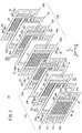
図1は、本発明の実施形態に係る燃料電池スタック10の要部分解斜視説明図である。
FIG. 1 is an exploded perspective view of a main part of a
燃料電池スタック10は、第1の発電ユニット12Aと第2の発電ユニット12Bとを水平方向(矢印A方向)に沿って交互に積層して構成される。第1の発電ユニット12Aは、図2に示すように、第1金属セパレータ14A、第1電解質膜・電極構造体(MEA)(電解質・電極構造体)16a、第2金属セパレータ18A、第2電解質膜・電極構造体16b及び第3金属セパレータ20Aを設ける。なお、第1の発電ユニット12Aは、4個以上の偶数個のMEAを含むことも可能である。
The
第1金属セパレータ14A、第2金属セパレータ18A及び第3金属セパレータ20Aは、例えば、鋼板、ステンレス鋼板、アルミニウム板、めっき処理鋼板、あるいはその金属表面に防食用の表面処理を施した金属板により構成される。第1金属セパレータ14A、第2金属セパレータ18A及び第3金属セパレータ20Aは、金属製薄板を波形状にプレス加工することにより、断面凹凸形状を有する。
The
第1及び第2電解質膜・電極構造体16a、16bは、例えば、パーフルオロスルホン酸の薄膜に水が含浸された固体高分子電解質膜22と、前記固体高分子電解質膜22を挟持するアノード側電極24及びカソード側電極26とを備える。
The first and second electrolyte membrane /
アノード側電極24及びカソード側電極26は、カーボンペーパ等からなるガス拡散層(図示せず)と、白金合金が表面に担持された多孔質カーボン粒子が前記ガス拡散層の表面に一様に塗布されて形成される電極触媒層(図示せず)とを有する。電極触媒層は、固体高分子電解質膜22の両面に形成される。
The
第1の発電ユニット12Aの長辺方向の(矢印B方向)一端縁部には、矢印A方向に互いに連通して、燃料ガス、例えば、水素含有ガスを供給するための燃料ガス入口連通孔30a、冷却媒体を供給するための冷却媒体入口連通孔32a、及び酸化剤ガス、例えば、酸素含有ガスを排出するための酸化剤ガス出口連通孔34bが設けられる。
A fuel gas
第1の発電ユニット12Aの長辺方向の(矢印B方向)他端縁部には、矢印A方向に互いに連通して、酸化剤ガスを供給するための酸化剤ガス入口連通孔34a、冷却媒体を排出するための冷却媒体出口連通孔32b、及び燃料ガスを排出するための燃料ガス出口連通孔30bが設けられる。
An oxidant gas
第1金属セパレータ14Aの第1電解質膜・電極構造体16aに向かう面14aには、酸化剤ガス入口連通孔34aと酸化剤ガス出口連通孔34bとを連通する第1酸化剤ガス流路36が形成される。第1酸化剤ガス流路36は、矢印B方向に延在する複数の流路溝36aを有する。
On the
第1酸化剤ガス流路36の入口及び出口近傍(少なくとも一方でもよい)には、入口バッファ部38及び出口バッファ部40が設けられる。入口バッファ部38と出口バッファ部40とは、中間高さから表裏に凸形状を有しており、面14a側(第1電解質膜・電極構造体16a側)に突出する複数の凸部(エンボス)38a、40aと、面14b側に突出する複数の凸部(エンボス)38b、40bとを有する。凸部38a、38b、40a及び40bは、円形、長円形又は矩形等、種々の形状に設定可能である。なお、以下のエンボスについても同様である。
An
第1金属セパレータ14Aの面14bには、冷却媒体入口連通孔32aと冷却媒体出口連通孔32bとを連通する冷却媒体流路44の一部が形成される。面14bには、第1酸化剤ガス流路36を構成する複数の流路溝36aの裏面形状である複数の流路溝(凹部)44aが形成される。流路溝44aの入口及び出口近傍には、複数の凸部40b、38bを有するバッファ部裏面形状が設けられる。
A part of the cooling
第2金属セパレータ18Aの第1電解質膜・電極構造体16aに向かう面18aには、燃料ガス入口連通孔30aと燃料ガス出口連通孔30bとを連通する第1燃料ガス流路46が形成される。第1燃料ガス流路46は、矢印B方向に延在する複数の流路溝(凹部)46aを有するとともに、前記第1燃料ガス流路46の入口及び出口近傍には、それぞれ入口バッファ部48及び出口バッファ部50が設けられる。
A first
入口バッファ部48と出口バッファ部50とは、中間高さから表裏に凸形状を有しており、面18a側(第1電解質膜・電極構造体16a側)に突出する複数の凸部(エンボス)48a、50aと、面18b側(第2電解質膜・電極構造体16b側)に突出する複数の凸部(エンボス)48b、50bとを有する。
The inlet buffer portion 48 and the
第2金属セパレータ18Aの第2電解質膜・電極構造体16bに向かう面18bには、酸化剤ガス入口連通孔34aと酸化剤ガス出口連通孔34bとを連通する第2酸化剤ガス流路52が形成される。第2酸化剤ガス流路52は、矢印B方向に延在する複数の流路溝(凹部)52aを有するとともに、前記第2酸化剤ガス流路52の入口及び出口近傍には、入口バッファ部54及び出口バッファ部56が設けられる。第2酸化剤ガス流路52は、第1燃料ガス流路46の裏面形状である一方、入口バッファ部54及び出口バッファ部56は、入口バッファ部54及び出口バッファ部56の裏面形状である。
On the
第3金属セパレータ20Aの第2電解質膜・電極構造体16bに向かう面20aには、燃料ガス入口連通孔30aと燃料ガス出口連通孔30bとを連通する第2燃料ガス流路58が形成される。第2燃料ガス流路58は、矢印B方向に延在する複数の流路溝(凹部)58aを有する。第2燃料ガス流路58の入口及び出口近傍には、入口バッファ部60及び出口バッファ部62が設けられる。
A second fuel
入口バッファ部60と出口バッファ部62とは、中間高さから表裏に凸形状を有しており、面20a側(第2電解質膜・電極構造体16b側)に突出する複数の凸部(エンボス)60a、62aと、面20b側(第2発電セル12B側)に突出する複数の凸部(エンボス)60b、62bとを有する。
The
第3金属セパレータ20Aの面20bには、冷却媒体流路44の一部が形成される。面20bには、第2燃料ガス流路58を構成する複数の流路溝58aの裏面形状である複数の流路溝(凹部)44bが形成される。
A part of the
第1の発電ユニット12Aでは、第1金属セパレータ14Aと第2金属セパレータ18Aとで、第1電解質膜・電極構造体16aを挟持する際、互いに対向する第1酸化剤ガス流路36と第1燃料ガス流路46とは、それぞれの流路溝36a、46a間の凸部が積層方向に同一位置に配置される。同様に、第2金属セパレータ18Aと第3金属セパレータ20Aとで、第2電解質膜・電極構造体16bを挟持する際、第2酸化剤ガス流路52と第2燃料ガス流路58とは、それぞれの流路溝52a、58a間の凸部同士が積層方向に同一位置に配置される。
In the first
各エンボスでは、図3に示すように、第1金属セパレータ14Aと第2金属セパレータ18Aとにおいて、互いに第1電解質膜・電極構造体16a側に突出する凸部40aと48a及び38aと50aとは、積層方向に互いに同一の位置に配置される。
In each emboss, as shown in FIG. 3, in the
第2金属セパレータ18Aと第3金属セパレータ20Aとにおいて、第2電解質膜・電極構造体16b側に突出する凸部48bと60a及び50bと62aとは、積層方向に互いに同一の位置に配置される。
In the
図2に示すように、第1金属セパレータ14Aの面14a、14bには、この第1金属セパレータ14Aの外周端縁部を周回して第1シール部材64が一体成形される。第2金属セパレータ18Aの面18a、18bには、この第2金属セパレータ18Aの外周端縁部を周回して第2シール部材66が一体成形されるとともに、第3金属セパレータ20Aの面20a、20bには、この第3金属セパレータ20Aの外周端縁部を周回して第3シール部材68が一体成形される。
As shown in FIG. 2, the
図1に示すように、第2の発電ユニット12Bは、第1金属セパレータ14B、第1電解質膜・電極構造体16a、第2金属セパレータ18B、第2電解質膜・電極構造体16b及び第3金属セパレータ20Bを設ける。なお、第1の発電ユニット12Aと同一の構成要素には同一の参照符号を付して、その詳細な説明は省略する。
As shown in FIG. 1, the second
第2の発電ユニット12Bでは、入口バッファ部38、48、54及び60と、出口バッファ部40、50、56及び62のエンボス形状が、第1の発電ユニット12Aとは異なる位相、すなわち、千鳥状に構成される(図3参照)。
In the second
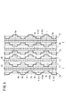
図3及び図4に示すように、第1の発電ユニット12Aを構成する第3金属セパレータ20Aと、第2の発電ユニット12Bを構成する第1金属セパレータ14Bとの間には、冷却媒体流路44が形成される。冷却媒体流路44の両端部側には、第3金属セパレータ20A及び第1金属セパレータ14Bから互いに対向して突出する凸部60bと40b及び凸部62bと38bとが、積層方向に互いに同一の位置に配置される。なお、流路溝44b、44aは、互いに凸部同士が積層方向に同一位置に配置されることが好ましい。
As shown in FIGS. 3 and 4, a cooling medium flow path is provided between the
このように構成される燃料電池スタック10の動作について、以下に説明する。
The operation of the
先ず、図1に示すように、酸化剤ガス入口連通孔34aに酸素含有ガス等の酸化剤ガスが供給されるとともに、燃料ガス入口連通孔30aに水素含有ガス等の燃料ガスが供給される。さらに、冷却媒体入口連通孔32aに純水やエチレングリコール、オイル等の冷却媒体が供給される。
First, as shown in FIG. 1, an oxidant gas such as an oxygen-containing gas is supplied to the oxidant gas
このため、第1の発電ユニット12Aでは、図2に示すように、酸化剤ガスは、酸化剤ガス入口連通孔34aから第1金属セパレータ14Aの第1酸化剤ガス流路36及び第2金属セパレータ18Aの第2酸化剤ガス流路52に導入される。この酸化剤ガスは、第1酸化剤ガス流路36に沿って矢印B方向(水平方向)に移動し、第1電解質膜・電極構造体16aのカソード側電極26に供給されるとともに、第2酸化剤ガス流路52に沿って矢印B方向に移動し、第2電解質膜・電極構造体16bのカソード側電極26に供給される。
Therefore, in the first
一方、燃料ガスは、燃料ガス入口連通孔30aから第2金属セパレータ18Aの第1燃料ガス流路46に沿って水平方向(矢印B方向)に移動し、第1電解質膜・電極構造体16aのアノード側電極24に供給される。また、燃料ガスは、第3金属セパレータ20Aの第2燃料ガス流路58に沿って矢印B方向に移動し、第2電解質膜・電極構造体16bのアノード側電極24に供給される。
On the other hand, the fuel gas moves in the horizontal direction (in the direction of arrow B) along the first fuel
従って、第1及び第2電解質膜・電極構造体16a、16bでは、カソード側電極26に供給される酸化剤ガスと、アノード側電極24に供給される燃料ガスとが、電極触媒層内で電気化学反応により消費されて発電が行われる。
Therefore, in the first and second electrolyte membrane /
次いで、第1及び第2電解質膜・電極構造体16a、16bの各カソード側電極26に供給されて消費された酸化剤ガスは、酸化剤ガス出口連通孔34bに沿って矢印A方向に排出される。同様に、第1及び第2電解質膜・電極構造体16a、16bの各アノード側電極24に供給されて消費された燃料ガスは、燃料ガス出口連通孔30bに排出される。
Next, the oxidant gas consumed by being supplied to the cathode-
一方、冷却媒体入口連通孔32aに供給された冷却媒体は、図3及び図4に示すように、第1の発電ユニット12Aを構成する第3金属セパレータ20Aと、第2の発電ユニット12Bを構成する第1金属セパレータ14Aとの間に形成された冷却媒体流路44に導入された後、矢印B方向に流通する。この冷却媒体は、第1及び第2電解質膜・電極構造体16a、16bを冷却した後、冷却媒体出口連通孔32bに排出される。
On the other hand, as shown in FIGS. 3 and 4, the cooling medium supplied to the cooling medium
また、第2の発電ユニット12Bでは、上記の第1の発電ユニット12Aと同様に、第1及び第2電解質膜・電極構造体16a、16bにより発電が行われる。
In the second
この場合、本実施形態では、図3に示すように、第1の発電ユニット12Aでは、第1電解質膜・電極構造体16a側に突出する第1金属セパレータ14Aの凸部40a、38aと、前記第1電解質膜・電極構造体16aに突出する第2金属セパレータ18Aの凸部48a、50aとは、互いに積層方向に同一位置に配置されている。
In this case, in the present embodiment, as shown in FIG. 3, in the first
さらに、第2電解質膜・電極構造体16b側に突出する第2金属セパレータ18Aの凸部48b、50bと、第3金属セパレータ20Bの凸部60a、62aとは、積層方向に互いに同一位置に配置されている。このため、第1及び第2電解質膜・電極構造体16a、16bにせん断力が付与されることがなく、前記第1及び第2電解質膜・電極構造体16a、16bの損傷を良好に阻止することができるという効果がある。
Furthermore, the
しかも、第1の発電ユニット12Aと、第2の発電ユニット12Bとでは、それぞれの凸部38a、38b、40a、40b、48a、48b、50a、50b、60a、60b、62a及び62bは、互いに千鳥状に(位相をずらして)配置されている。
Moreover, in the first
第1の発電ユニット12Aと第2の発電ユニット12Bとは、それぞれ偶数個、例えば、2個のMEA、すなわち、第1及び第2電解質膜・電極構造体16a、16bと、奇数枚、例えば、3枚のセパレータ、すなわち、第1金属セパレータ14A、14B、第2金属セパレータ18A、18B及び第3金属セパレータ20A、28Bとを備えている。このため、凸部40a、38aと凸部48b、50bとは、千鳥状に配置されるとともに、凸部48a、50aと凸部60a、62aとは、千鳥状に配置されている。
Each of the first
従って、第1の発電ユニット12Aと第2の発電ユニット12Bとの間に形成される冷却媒体流路44では、その両端側にバッファ裏面形状となる凸部60bと凸部40bとは、積層方向に同一位置に配置されるとともに、凸部62bと凸部38bとは、同様に、積層方向に同一位置に配置されている。
Therefore, in the cooling
これにより、冷却媒体流路44で、凸部60b、40b同士及び凸部62b、38b同士が積層方向に当接することができ(図3参照)、前記積層方向の荷重及び発電時の圧力変動を確実に保持する構造を設けることが可能になる。このため、第1の発電ユニット12Aと第2の発電ユニット12Bとの間での電気伝導性の低下やMEA変形及びセパレータ変形による破損等を惹起することがない。従って、第1の発電ユニット12Aと第2の発電ユニット12Bとを交互に積層するだけでよく、燃料電池スタック10を簡単且つ経済的に構成することが可能になるという効果が得られる。
Thereby, in the cooling
10…燃料電池スタック 12A、12B…発電ユニット
14A、14B、18A、18B、20A、20B…金属セパレータ
16a、16b…電解質膜・電極構造体
22…固体高分子電解質膜 24…アノード側電極
26…カソード側電極 36、52…酸化剤ガス流路
38、48、54、60…入口バッファ部
38a、38b、40a、40b、48a、48b、50a、50b、60a、60b、62a、62b…凸部
40、50、56、62…出口バッファ部
44…冷却媒体流路 46、58…燃料ガス流路
DESCRIPTION OF
Claims (2)
前記第1の発電ユニットは、前記バッファ部の前記燃料ガス流路側の凸部と前記酸化剤ガス流路側の凸部とが、各電解質・電極構造体を挟んで積層方向に互いに同一の位置に配置される一方、
前記第2の発電ユニットは、前記バッファ部の前記燃料ガス流路側の凸部と前記酸化剤ガス流路側の凸部とが、各電解質・電極構造体を挟んで積層方向に互いに同一の位置に且つ前記第1の発電ユニットの前記バッファ部の前記凸部とは千鳥状に配置されることを特徴とする燃料電池スタック。 The anode side electrode and the cathode side electrode have an even number of electrolyte / electrode structures provided on both sides of the electrolyte, and metal separators alternately stacked with the electrolyte / electrode assemblies. The fuel gas flow path for supplying the fuel gas and the oxidant gas flow path for supplying the oxidant gas to the cathode-side electrode each have at least a flow path inlet or a flow path outlet provided with a concavo-convex shaped buffer portion. A fuel cell stack comprising units and alternately stacked by forming a cooling medium flow path between a first power generation unit and a second power generation unit,
In the first power generation unit, the convex portion on the fuel gas flow path side and the convex portion on the oxidant gas flow path side of the buffer portion are located at the same position in the stacking direction with each electrolyte / electrode structure interposed therebetween. While placed
In the second power generation unit, the convex part on the fuel gas flow path side and the convex part on the oxidant gas flow path side of the buffer section are located at the same position in the stacking direction with each electrolyte / electrode structure interposed therebetween. The fuel cell stack is arranged in a staggered manner with respect to the convex portions of the buffer portion of the first power generation unit.
Priority Applications (6)
| Application Number | Priority Date | Filing Date | Title |
|---|---|---|---|
| JP2008169033A JP5334469B2 (en) | 2008-06-27 | 2008-06-27 | Fuel cell stack |
| CN200980124219.XA CN102077402B (en) | 2008-06-27 | 2009-06-05 | Fuel cell stack |
| US13/000,963 US8465880B2 (en) | 2008-06-27 | 2009-06-05 | Fuel cell stack |
| EP09770000.9A EP2296213B1 (en) | 2008-06-27 | 2009-06-05 | Fuel cell stack |
| PCT/JP2009/060336 WO2009157290A1 (en) | 2008-06-27 | 2009-06-05 | Fuel cell stack |
| CA2728953A CA2728953C (en) | 2008-06-27 | 2009-06-05 | Fuel cell assembly having embossed separator plates |
Applications Claiming Priority (1)
| Application Number | Priority Date | Filing Date | Title |
|---|---|---|---|
| JP2008169033A JP5334469B2 (en) | 2008-06-27 | 2008-06-27 | Fuel cell stack |
Publications (2)
| Publication Number | Publication Date |
|---|---|
| JP2010009979A true JP2010009979A (en) | 2010-01-14 |
| JP5334469B2 JP5334469B2 (en) | 2013-11-06 |
Family
ID=41444359
Family Applications (1)
| Application Number | Title | Priority Date | Filing Date |
|---|---|---|---|
| JP2008169033A Active JP5334469B2 (en) | 2008-06-27 | 2008-06-27 | Fuel cell stack |
Country Status (6)
| Country | Link |
|---|---|
| US (1) | US8465880B2 (en) |
| EP (1) | EP2296213B1 (en) |
| JP (1) | JP5334469B2 (en) |
| CN (1) | CN102077402B (en) |
| CA (1) | CA2728953C (en) |
| WO (1) | WO2009157290A1 (en) |
Families Citing this family (9)
| Publication number | Priority date | Publication date | Assignee | Title |
|---|---|---|---|---|
| JP5274904B2 (en) * | 2008-06-17 | 2013-08-28 | 本田技研工業株式会社 | Fuel cell stack |
| JP2014096358A (en) * | 2012-10-11 | 2014-05-22 | Honda Motor Co Ltd | Fuel cell stack |
| JP6059036B2 (en) * | 2013-02-18 | 2017-01-11 | 本田技研工業株式会社 | Fuel cell stack |
| CA2920472A1 (en) * | 2013-08-05 | 2015-02-12 | Nissan Motor Co., Ltd. | Deformation absorbing member and fuel cell |
| DE102014206336A1 (en) * | 2014-04-02 | 2015-10-08 | Volkswagen Ag | Bipolar plate, fuel cell and a motor vehicle |
| JP6607471B2 (en) * | 2016-06-10 | 2019-11-20 | 日産自動車株式会社 | Fuel cell stack and separator for fuel cell stack |
| CN113299964B (en) * | 2016-10-06 | 2022-12-23 | 本田技研工业株式会社 | Fuel cell stack |
| WO2019189058A1 (en) * | 2018-03-30 | 2019-10-03 | 本田技研工業株式会社 | Fuel cell |
| CN110854404B (en) * | 2018-08-21 | 2021-07-30 | 上海汽车集团股份有限公司 | Fuel cell bipolar plate and electric pile |
Citations (5)
| Publication number | Priority date | Publication date | Assignee | Title |
|---|---|---|---|---|
| JP2000208153A (en) * | 1999-01-18 | 2000-07-28 | Fuji Electric Co Ltd | Solid polymer electrolyte fuel cell |
| JP2001176519A (en) * | 1999-12-15 | 2001-06-29 | Matsushita Electric Ind Co Ltd | Conductive separator, high molecular electrolyte-type fuel cell and method of manufacturing high molecular electrolyte-type fuel cell |
| JP2004087311A (en) * | 2002-08-27 | 2004-03-18 | Honda Motor Co Ltd | Fuel cell stack and metallic separator for for fuel cell stack |
| JP2005235555A (en) * | 2004-02-19 | 2005-09-02 | Honda Motor Co Ltd | Fuel cell |
| JP2006252803A (en) * | 2005-03-08 | 2006-09-21 | Honda Motor Co Ltd | Fuel cell |
Family Cites Families (6)
| Publication number | Priority date | Publication date | Assignee | Title |
|---|---|---|---|---|
| JPH08222237A (en) | 1995-02-14 | 1996-08-30 | Aisin Aw Co Ltd | Separator for fuel cell |
| JP3599280B2 (en) * | 2002-05-17 | 2004-12-08 | 本田技研工業株式会社 | Fuel cell |
| CN1692515A (en) * | 2003-12-12 | 2005-11-02 | Lg电子株式会社 | Bipolar plate of fuel cell |
| CA2540773C (en) * | 2005-03-25 | 2011-10-18 | Honda Motor Co., Ltd. | Fuel cell with gas separator which discharges retained water |
| JP5077620B2 (en) * | 2005-12-16 | 2012-11-21 | トヨタ自動車株式会社 | Fuel cell separator |
| JP4908912B2 (en) * | 2006-04-28 | 2012-04-04 | 本田技研工業株式会社 | Fuel cell stack |
-
2008
- 2008-06-27 JP JP2008169033A patent/JP5334469B2/en active Active
-
2009
- 2009-06-05 CN CN200980124219.XA patent/CN102077402B/en active Active
- 2009-06-05 WO PCT/JP2009/060336 patent/WO2009157290A1/en active Application Filing
- 2009-06-05 CA CA2728953A patent/CA2728953C/en not_active Expired - Fee Related
- 2009-06-05 EP EP09770000.9A patent/EP2296213B1/en not_active Not-in-force
- 2009-06-05 US US13/000,963 patent/US8465880B2/en active Active
Patent Citations (5)
| Publication number | Priority date | Publication date | Assignee | Title |
|---|---|---|---|---|
| JP2000208153A (en) * | 1999-01-18 | 2000-07-28 | Fuji Electric Co Ltd | Solid polymer electrolyte fuel cell |
| JP2001176519A (en) * | 1999-12-15 | 2001-06-29 | Matsushita Electric Ind Co Ltd | Conductive separator, high molecular electrolyte-type fuel cell and method of manufacturing high molecular electrolyte-type fuel cell |
| JP2004087311A (en) * | 2002-08-27 | 2004-03-18 | Honda Motor Co Ltd | Fuel cell stack and metallic separator for for fuel cell stack |
| JP2005235555A (en) * | 2004-02-19 | 2005-09-02 | Honda Motor Co Ltd | Fuel cell |
| JP2006252803A (en) * | 2005-03-08 | 2006-09-21 | Honda Motor Co Ltd | Fuel cell |
Also Published As
| Publication number | Publication date |
|---|---|
| CN102077402A (en) | 2011-05-25 |
| CN102077402B (en) | 2014-09-24 |
| EP2296213A4 (en) | 2011-11-02 |
| EP2296213A1 (en) | 2011-03-16 |
| WO2009157290A1 (en) | 2009-12-30 |
| US8465880B2 (en) | 2013-06-18 |
| US20110159395A1 (en) | 2011-06-30 |
| JP5334469B2 (en) | 2013-11-06 |
| CA2728953C (en) | 2013-02-26 |
| CA2728953A1 (en) | 2009-12-30 |
| EP2296213B1 (en) | 2013-09-25 |
Similar Documents
| Publication | Publication Date | Title |
|---|---|---|
| US7531265B2 (en) | Fuel cell | |
| JP5334469B2 (en) | Fuel cell stack | |
| JP5226431B2 (en) | Fuel cell stack | |
| JP4906891B2 (en) | Fuel cell | |
| JP5227543B2 (en) | Fuel cell | |
| JP4268536B2 (en) | Fuel cell | |
| JP2011258323A (en) | Fuel cell stack | |
| JP5235351B2 (en) | Fuel cell | |
| JP5274904B2 (en) | Fuel cell stack | |
| JP5191951B2 (en) | Fuel cell | |
| JP2008293743A (en) | Fuel cell | |
| JP2007207570A (en) | Fuel cell | |
| JP5274908B2 (en) | Fuel cell stack | |
| JP2005268151A (en) | Fuel cell | |
| JP5265289B2 (en) | Fuel cell stack | |
| JP4422505B2 (en) | Fuel cell | |
| JP2004172004A (en) | Fuel cell | |
| JP5203060B2 (en) | Fuel cell stack | |
| JP2008243499A (en) | Fuel cell | |
| JP5318715B2 (en) | Polymer electrolyte fuel cell | |
| JP5336221B2 (en) | Fuel cell stack | |
| JP4701304B2 (en) | Fuel cell | |
| JP5144388B2 (en) | Fuel cell stack | |
| JP5632417B2 (en) | Fuel cell | |
| JP2009266828A (en) | Fuel cell |
Legal Events
| Date | Code | Title | Description |
|---|---|---|---|
| A621 | Written request for application examination |
Free format text: JAPANESE INTERMEDIATE CODE: A621 Effective date: 20101125 |
|
| A131 | Notification of reasons for refusal |
Free format text: JAPANESE INTERMEDIATE CODE: A131 Effective date: 20130122 |
|
| A521 | Written amendment |
Free format text: JAPANESE INTERMEDIATE CODE: A523 Effective date: 20130319 |
|
| A131 | Notification of reasons for refusal |
Free format text: JAPANESE INTERMEDIATE CODE: A131 Effective date: 20130507 |
|
| A521 | Written amendment |
Free format text: JAPANESE INTERMEDIATE CODE: A523 Effective date: 20130611 |
|
| TRDD | Decision of grant or rejection written | ||
| A01 | Written decision to grant a patent or to grant a registration (utility model) |
Free format text: JAPANESE INTERMEDIATE CODE: A01 Effective date: 20130702 |
|
| A61 | First payment of annual fees (during grant procedure) |
Free format text: JAPANESE INTERMEDIATE CODE: A61 Effective date: 20130730 |
|
| R150 | Certificate of patent or registration of utility model |
Ref document number: 5334469 Country of ref document: JP Free format text: JAPANESE INTERMEDIATE CODE: R150 Free format text: JAPANESE INTERMEDIATE CODE: R150 |
|
| R250 | Receipt of annual fees |
Free format text: JAPANESE INTERMEDIATE CODE: R250 |