JP2010009827A - Wire harness - Google Patents
Wire harness Download PDFInfo
- Publication number
- JP2010009827A JP2010009827A JP2008165716A JP2008165716A JP2010009827A JP 2010009827 A JP2010009827 A JP 2010009827A JP 2008165716 A JP2008165716 A JP 2008165716A JP 2008165716 A JP2008165716 A JP 2008165716A JP 2010009827 A JP2010009827 A JP 2010009827A
- Authority
- JP
- Japan
- Prior art keywords
- flat cable
- press contact
- wire harness
- wire
- contact blade
- Prior art date
- Legal status (The legal status is an assumption and is not a legal conclusion. Google has not performed a legal analysis and makes no representation as to the accuracy of the status listed.)
- Granted
Links
- 230000001154 acute effect Effects 0.000 claims description 5
- 230000008878 coupling Effects 0.000 abstract 3
- 238000010168 coupling process Methods 0.000 abstract 3
- 238000005859 coupling reaction Methods 0.000 abstract 3
- 239000011295 pitch Substances 0.000 description 22
- 229920003002 synthetic resin Polymers 0.000 description 3
- 239000000057 synthetic resin Substances 0.000 description 3
- 239000002184 metal Substances 0.000 description 2
- 238000013459 approach Methods 0.000 description 1
- 238000005452 bending Methods 0.000 description 1
- 239000011248 coating agent Substances 0.000 description 1
- 238000000576 coating method Methods 0.000 description 1
- 238000006073 displacement reaction Methods 0.000 description 1
- 238000012986 modification Methods 0.000 description 1
- 230000004048 modification Effects 0.000 description 1
Images


Classifications
-
- H—ELECTRICITY
- H01—ELECTRIC ELEMENTS
- H01R—ELECTRICALLY-CONDUCTIVE CONNECTIONS; STRUCTURAL ASSOCIATIONS OF A PLURALITY OF MUTUALLY-INSULATED ELECTRICAL CONNECTING ELEMENTS; COUPLING DEVICES; CURRENT COLLECTORS
- H01R12/00—Structural associations of a plurality of mutually-insulated electrical connecting elements, specially adapted for printed circuits, e.g. printed circuit boards [PCB], flat or ribbon cables, or like generally planar structures, e.g. terminal strips, terminal blocks; Coupling devices specially adapted for printed circuits, flat or ribbon cables, or like generally planar structures; Terminals specially adapted for contact with, or insertion into, printed circuits, flat or ribbon cables, or like generally planar structures
- H01R12/50—Fixed connections
- H01R12/59—Fixed connections for flexible printed circuits, flat or ribbon cables or like structures
- H01R12/65—Fixed connections for flexible printed circuits, flat or ribbon cables or like structures characterised by the terminal
- H01R12/67—Fixed connections for flexible printed circuits, flat or ribbon cables or like structures characterised by the terminal insulation penetrating terminals
- H01R12/675—Fixed connections for flexible printed circuits, flat or ribbon cables or like structures characterised by the terminal insulation penetrating terminals with contacts having at least a slotted plate for penetration of cable insulation, e.g. insulation displacement contacts for round conductor flat cables
Abstract
Description
本発明は、自動車などに配索されて各種電子機器に電力や信号を伝送するワイヤハーネスに関するものである。 The present invention relates to a wire harness that is wired in an automobile or the like and transmits electric power and signals to various electronic devices.
種々の電子機器が搭載される自動車には、これら電子機器に電力や信号を伝送するワイヤハーネスが配索されている。このワイヤハーネスは、例えば、複数の電線と、複数の端子を有するコネクタなどを有している。前記端子は、前記電線と他の電線とを接続したり、前記電線と電子機器とを接続したりするためのものである。 In a vehicle on which various electronic devices are mounted, a wire harness that transmits electric power and signals to these electronic devices is routed. The wire harness includes, for example, a connector having a plurality of electric wires and a plurality of terminals. The said terminal is for connecting the said electric wire and another electric wire, or connecting the said electric wire and an electronic device.
また、前述した電線として、複数の電線同士が連結部により一体に形成されたフラットケーブルを用いることがある。そして、前記フラットケーブルの電線と他の電線とを接続する場合や、前記フラットケーブルの電線と電子機器とを接続する場合には、「圧接端子」と呼ばれる端子が用いられる(例えば、特許文献1を参照)。 Moreover, the flat cable in which several electric wires were integrally formed by the connection part may be used as an electric wire mentioned above. And when connecting the electric wire of the said flat cable, and another electric wire, or when connecting the electric wire of the said flat cable, and an electronic device, the terminal called a "pressure contact terminal" is used (for example, patent document 1). See).
図11は従来のワイヤハーネスのフラットケーブルに圧接刃が突き刺される前の状態を示す断面図である。図12は図11に示されたフラットケーブルに圧接刃が突き刺された状態を示す断面図である。 FIG. 11 is a cross-sectional view showing a state before a press contact blade is pierced into a flat cable of a conventional wire harness. FIG. 12 is a cross-sectional view showing a state in which a press contact blade is pierced into the flat cable shown in FIG.
図11及び図12に示すワイヤハーネス301は、複数の電線305と互いに隣り合う電線305同士を連結した連結部306とを有するフラットケーブル302と、電子機器のハウジング304に取り付けられた複数の圧接端子303と、を有している。
A
前記フラットケーブル302の電線305は、導電性の芯線321と、芯線321を被覆した被覆部322と、を有している。また、前記被覆部322と前記連結部306とは、絶縁性の合成樹脂で構成され、互いに一体に形成されている。このようなフラットケーブル302は、帯状に形成されており、可撓性を有している。
The
前記複数の圧接端子303は、導電性の金属板にプレス加工が施されるなどして得られるものであり、前記電子機器の回路に接続された接続部(不図示)と、前記電子機器のハウジングから突出し、フラットケーブル302に突き刺さって前記芯線321に接触する圧接刃330と、を有している。この圧接刃330は、互いの間に芯線321を位置付けるための間隔が設けられた一対の刃部331と、これら刃部331のハウジング寄りの端部同士を連結した刃部連結部333と、を有している。また、これら複数の圧接刃330は、フラットケーブル302の幅方向に沿った間隔が変化することを規制された状態で前記幅方向に沿って並べられている。
The plurality of
また、前述したフラットケーブル302の、互いに隣り合う芯線321の中心間の間隔P6と、互いに隣り合う圧接刃330の中心間の間隔P5と、は、等しく形成されている。
In addition, the interval P6 between the centers of the
上記構成のワイヤハーネス301は、図11に示すように、フラットケーブル302の長手方向の中間部における各芯線321の中心と各圧接刃330の中心とが位置合わせされ、そして、図12に示すように、フラットケーブル302と複数の圧接刃330とが互いに近付けられこれら圧接刃330がフラットケーブル302に突き刺されて各圧接刃330が各芯線321に接触することで、前記中間部における各電線305と各圧接端子303とが互いに電気接続される。
前述したように、ワイヤハーネス301においては、互いに隣り合う芯線321の中心間の間隔P6、即ち電線ピッチ、と、互いに隣り合う圧接刃330の中心間の間隔P5、即ち端子ピッチ、とが等しくなるように設計するのが最も理想的であった。しかしながら、前記電子機器の小型化やフラットケーブル302の細線化により、前記電線ピッチと前記端子ピッチとを等しくすることが困難になってきているという問題があった。
As described above, in the
また、圧接刃330をフラットケーブル302に突き刺す際には大きな力が必要であることから、前記電子機器の小型化やフラットケーブル302の細線化によって圧接刃330を小型化すると、この圧接刃330をフラットケーブル302に突き刺す際に圧接刃330が曲がってしまったり、圧接刃330と電線305とが位置ずれしてしまったりすることが起こり得るという問題があった。
In addition, since a large force is required to pierce the
また、前述した問題は、複数の圧接端子303がコネクタのハウジングに取り付けられている場合にも同様に生じる問題である。
The above-described problem is also a problem that occurs when a plurality of
したがって、本発明は、複数の電線が連結部によって一体に形成されたフラットケーブルと前記電線に接続される複数の圧接刃とを有するワイヤハーネスにおいて、電線ピッチと端子ピッチとが互いに異なるフラットケーブルと複数の圧接刃とを接続することが可能なワイヤハーネスを提供することを目的とする。 Therefore, the present invention provides a wire harness having a flat cable in which a plurality of electric wires are integrally formed by a connecting portion and a plurality of press contact blades connected to the electric wires, and a flat cable having a different electric wire pitch and terminal pitch. An object of the present invention is to provide a wire harness capable of connecting a plurality of press contact blades.
上記目的を達成するために、請求項1に記載された発明は、複数の電線と互いに隣り合う前記電線同士を連結した連結部とを有するフラットケーブルと、前記フラットケーブルの幅方向に沿った間隔が変化することを規制された状態で前記幅方向に沿って複数並べられ、前記フラットケーブルの長手方向の中間部に突き刺さって前記電線の芯線に接触した複数の圧接刃と、を有するワイヤハーネスであって、前記連結部の前記中間部に位置する部分にスリットが設けられ、そして、前記複数の電線の前記中間部に位置する部分同士が、前記スリットの幅を狭める格好で互いに近付けられることで前記圧接刃に電気接続可能な位置に位置付けられていることを特徴とするワイヤハーネスである。
In order to achieve the above object, the invention described in
請求項2に記載された発明は、請求項1に記載された発明において、前記圧接刃の一部が前記スリット内に位置付けられていることを特徴とするものである。
The invention described in
請求項3に記載された発明は、請求項1または請求項2に記載された発明において、前記圧接刃が、鋭角に形成され、前記中間部に突き刺さる際に前記スリット内を通される先端部を有していることを特徴とするものである。 According to a third aspect of the present invention, in the first or second aspect of the present invention, the pressure contact blade is formed at an acute angle, and is passed through the slit when piercing the intermediate portion. It is characterized by having.
請求項4に記載された発明は、請求項1ないし請求項3のうち1項に記載された発明において、前記フラットケーブルの幅方向に沿って互いに隣り合う前記圧接刃同士が、前記フラットケーブルの長手方向に沿って位置ずれした位置に配置されるとともに、これら互いに隣り合う圧接刃の中心間の間隔が当該圧接刃の幅よりも小さくなる位置に配置されていることを特徴とするものである。
The invention described in
請求項1に記載された発明によれば、前記連結部の前記中間部に位置する部分にスリットが設けられ、そして、前記複数の電線の前記中間部に位置する部分同士が、前記スリットの幅を狭める格好で互いに近付けられることで前記圧接刃に電気接続可能な位置に位置付けられているので、電線ピッチと端子ピッチとが互いに異なるフラットケーブルと圧接刃とを接続することが可能なワイヤハーネスを提供することができる。
According to the invention described in
請求項2に記載された発明によれば、前記圧接刃の一部が前記スリット内に位置付けられているので、圧接刃をフラットケーブルに突き刺す際に大きな力は必要なくなり、そのために、圧接刃を小型化しても、圧接刃をフラットケーブルに突き刺す際に圧接刃が曲がったり、圧接刃と電線とが位置ずれすることを防止できる。
According to the invention described in
請求項3に記載された発明によれば、前記圧接刃が、鋭角に形成され、前記中間部に突き刺さる際に前記スリット内を通される先端部を有しているので、圧接刃をフラットケーブルに突き刺す際に大きな力は必要なくなり、そのために、圧接刃を小型化しても、圧接刃をフラットケーブルに突き刺す際に圧接刃が曲がったり、圧接刃と電線とが位置ずれすることを防止できる。 According to the invention described in claim 3, since the press contact blade is formed at an acute angle and has a tip portion that passes through the slit when piercing the intermediate portion, the press contact blade is connected to the flat cable. Therefore, even when the pressure contact blade is reduced in size, it is possible to prevent the pressure contact blade from being bent and the pressure contact blade and the electric wire from being displaced from each other even when the pressure contact blade is reduced in size.
請求項4に記載された発明によれば、前記フラットケーブルの幅方向に沿って互いに隣り合う前記圧接刃同士が、前記フラットケーブルの長手方向に沿って位置ずれした位置に配置されるとともに、これら互いに隣り合う圧接刃の中心間の間隔が当該圧接刃の幅よりも小さくなる位置に配置されているので、互いに隣り合う圧接刃の中心間の間隔、即ち端子ピッチ、を小さくすることができる。
According to the invention described in
(第1の実施形態)
以下、本発明の第1の実施形態に係るワイヤハーネスを図1ないし図6を用いて説明する。図1は本発明の第1の実施形態に係るワイヤハーネスを示す斜視図である。図2は図1に示されたワイヤハーネスのフラットケーブルに圧接刃が突き刺される前の状態を示す斜視図である。図3は図2中のA−A線に沿った断面図である。図4は図2中のB−B線に沿った断面図である。図5は図4に示されたフラットケーブルの中間部の幅が狭められた状態を示す断面図である。図6は図1中のC−C線に沿った断面図である。
(First embodiment)
Hereinafter, a wire harness according to a first embodiment of the present invention will be described with reference to FIGS. 1 to 6. FIG. 1 is a perspective view showing a wire harness according to a first embodiment of the present invention. FIG. 2 is a perspective view showing a state before the press contact blade is inserted into the flat cable of the wire harness shown in FIG. 3 is a cross-sectional view taken along the line AA in FIG. 4 is a cross-sectional view taken along line BB in FIG. FIG. 5 is a cross-sectional view showing a state where the width of the intermediate portion of the flat cable shown in FIG. 4 is narrowed. FIG. 6 is a cross-sectional view taken along line CC in FIG.
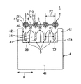
本発明のワイヤハーネス1は、自動車の車体に配索されて前記自動車に搭載された電子機器に電力供給や信号伝送を行うものである。このワイヤハーネス1は、図1及び図2に示すように、フラットケーブル2と、前記電子機器としてのルームランプのハウジング4に取り付けられ、前記フラットケーブル2の長手方向の中間部に接続された複数の圧接端子3と、を有している。また、図1ないし図6中の矢印Nは、フラットケーブル2の長手方向を示しており、矢印Hは、フラットケーブル2の幅方向を示している。
The
上記フラットケーブル2は、図3及び図4などに示すように、互いに平行かつ等間隔に配置された複数の電線5と、互いに隣り合う電線5同士を連結した連結部6と、を有している。前記電線5は、導電性の芯線21と、この芯線21を被覆した被覆部22と、を有している。また、前記被覆部22と前記連結部6とは、絶縁性の合成樹脂で構成され、互いに一体に形成されている。このようなフラットケーブル2は、帯状に形成されており、可撓性を有している。
As shown in FIGS. 3 and 4, the
上記フラットケーブル2は、互いに隣り合う電線5の芯線21の中心間の間隔(図3などにP2で示す。)が互いに等しく形成されている。また、各連結部6の前記中間部に位置する部分には、フラットケーブル2の長手方向に沿って延びたスリット7が設けられている。また、スリット7は、フラットケーブル2の厚み方向に沿って連結部6を貫通している。
In the
上記複数の圧接端子3は、導電性の金属板にプレス加工が施されるなどして得られるものであり、それぞれ、前記ルームランプの回路に接続された接続部(不図示)と、前記ハウジング4の平らな外表面41aから突出し、フラットケーブル2に突き刺さって前記芯線21に接触する圧接刃30と、を有している。
The plurality of press contact terminals 3 are obtained by, for example, pressing a conductive metal plate, a connection portion (not shown) connected to the circuit of the room lamp, and the
上記圧接刃30は、前記中間部に突き刺さった状態で互いの間に芯線21を位置付けるための間隔が設けられた一対の刃部31と、これら刃部31の前記外表面41a寄りの一端部同士を連結した刃部連結部33と、を有している。また、各刃部31は、その他端部に、鋭角に形成され、前記中間部に突き刺さる際に前記スリット7内を通される先端部32を有している(図5を参照。)。このような圧接刃30は、図1及び図6に示すように前記中間部に突き刺された状態で、その一部がスリット7内に位置付けられる。
The
また、上記複数の圧接刃30は、フラットケーブル2の幅方向に沿った間隔が変化することを規制された状態で前記幅方向に沿って並べられている。即ち、複数の圧接刃30は、ハウジング4に固定されている。
In addition, the plurality of
さらに、上記複数の圧接刃30は、フラットケーブル2の幅方向に沿って互いに隣り合う圧接刃30同士が、フラットケーブル2の長手方向に沿って位置ずれした位置に配置されるとともに、これら互いに隣り合う圧接刃30の中心間の間隔(図3などにP1で示す。)が当該圧接刃30の幅よりも小さくなる位置に配置されている。即ち、前記幅方向に沿って互いに隣り合う圧接刃30同士は、刃部31同士がラップする位置に配置されている。また、複数の圧接刃30は、前記幅方向に沿って互いに隣り合う圧接刃30の中心間の間隔(図3などにP1で示す。)が互いに等しく形成されている。
Further, the plurality of
さらに、前述したフラットケーブル2は、圧接端子3に接続される前の状態において、互いに隣り合う電線5の芯線21の中心間の間隔、即ち電線ピッチ、P2が、図3及び図4に示すように、複数の圧接端子3の互いに隣り合う圧接刃30の中心間の間隔、即ち端子ピッチ、P1よりも大きく形成されている。
Further, in the state before the
上記ハウジング4は、絶縁性の合成樹脂で構成されており、ブロック状の本体部41と、本体部41の上面即ち前記外表面41aから立設した一対の立設壁42と、を有している。また、一対の立設壁42は、本体部41の矢印Hに沿った両端部それぞれから立設し、矢印Nに沿って延びている。前述したフラットケーブル2は、複数の圧接端子3が突き刺された状態で、前記中間部が外表面41a上に位置付けられかつ一対の立設壁42間に位置付けられる。
The
前述したフラットケーブル2の複数の電線5の前記中間部に位置する部分に各圧接端子3を接続させる際には、図5に示すように、複数の電線5の前記中間部に位置する部分同士を各スリット7の幅を狭める格好で互いに近付けて、即ち前記中間部を変形させて、各芯線21の中心を各圧接刃30の中心上に位置付ける。また、この状態で、各スリット7が各圧接刃30の先端部32上に位置付けられる。
When each press contact terminal 3 is connected to the portion of the
そして、このフラットケーブル2と複数の圧接刃30とを互いに近付けて各圧接刃30を前記中間部に突き刺す。この際、圧接刃30は、初めに先端部32がスリット7内を通され、そして、フラットケーブル2が外表面41aに近付くにしたがって先端部32よりも刃部連結部33側の部分が、スリット7の外側の連結部6及び被覆部22に切り込んで芯線21に達する。
Then, the
こうして、図6に示すように、圧接刃30の一対の刃部31の内縁部それぞれが、芯線21に接触して、各圧接刃30と各電線5の芯線21とが互いに電気接続される。また、特許請求の範囲に記載した、「電線5が圧接刃30に電気接続可能な位置に位置付けられる」とは、図6に示す状態であり、フラットケーブル2の中間部の電線ピッチが端子ピッチと等しくされた状態で、各電線5の芯線21が一対の刃部31間に位置付けられて該刃部31に接触した状態を言う。
In this way, as shown in FIG. 6, the inner edge portions of the pair of
本発明によれば、フラットケーブル2の連結部6の中間部に位置する部分にスリット7が設けられ、そして、複数の電線5の前記中間部に位置する部分同士が、スリット7の幅を狭める格好で互いに近付けられることで圧接刃30に電気接続可能な位置に位置付けられているので、電線ピッチと端子ピッチとが互いに異なるフラットケーブル2と圧接刃30とを接続することが可能になる。
According to the present invention, the
また、圧接刃30が、鋭角に形成され、前記中間部に突き刺さる際にスリット7内を通される先端部32を有しているので、圧接刃30をフラットケーブル2に突き刺す際に大きな力は必要なくなり、そのために、圧接刃30を小型化しても、圧接刃30をフラットケーブル2に突き刺す際に圧接刃30が曲がったり、圧接刃30と電線5とが位置ずれすることを防止できる。
In addition, since the
また、フラットケーブル2の幅方向に沿って互いに隣り合う圧接刃30同士が、フラットケーブル2の長手方向に沿って位置ずれした位置に配置されるとともに、これら互いに隣り合う圧接刃30の中心間の間隔P1が当該圧接刃30の幅よりも小さくなる位置に配置されているので、互いに隣り合う圧接刃30の中心間の間隔、即ち端子ピッチ、P1を小さくすることができる。
Further, the
以上のことから、本発明では、小型化された電子機器に対応可能、即ち端子ピッチが小さい複数の圧接端子3に接続可能で、電線ピッチが小さく軽量なフラットケーブル2を有するワイヤハーネス1を提供することができる。
In view of the above, the present invention provides a
(第2の実施形態)
続いて、本発明の第2の実施形態に係るワイヤハーネスを図7ないし図10を用いて説明する。図7は本発明の第2の実施形態に係るワイヤハーネスを示す断面図であり、フラットケーブルの端部を示す断面図である。図8は図7に示されたワイヤハーネスを示す断面図であり、図7に示されたフラットケーブルの中間部を示す断面図である。図9は図8に示されたフラットケーブルの中間部の幅が狭められた状態を示す断面図である。図10は図9に示されたフラットケーブルの中間部に圧接刃が突き刺された状態を示す断面図である。また、図7ないし図10において、前述した第1の実施形態と同一構成部分には同一符号を付して説明を省略する。
(Second Embodiment)
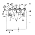
Subsequently, a wire harness according to a second embodiment of the present invention will be described with reference to FIGS. FIG. 7 is a cross-sectional view showing a wire harness according to a second embodiment of the present invention, and is a cross-sectional view showing an end portion of a flat cable. 8 is a cross-sectional view showing the wire harness shown in FIG. 7, and is a cross-sectional view showing an intermediate portion of the flat cable shown in FIG. FIG. 9 is a cross-sectional view showing a state where the width of the intermediate portion of the flat cable shown in FIG. 8 is narrowed. FIG. 10 is a cross-sectional view illustrating a state in which a press contact blade is pierced in an intermediate portion of the flat cable illustrated in FIG. 9. 7 to 10, the same components as those of the first embodiment described above are denoted by the same reference numerals, and description thereof is omitted.
本実施形態のワイヤハーネス101は、図7ないし図10に示すように、フラットケーブル102と、前記フラットケーブル102の長手方向の中間部に接続された複数の圧接端子3と、を有している。
As shown in FIGS. 7 to 10, the
上記フラットケーブル102は、互いに平行かつ等間隔に配置された複数の電線5と、互いに隣り合う電線5同士を連結した連結部106と、を有している。また、各連結部106の前記中間部に位置する部分には、フラットケーブル102の長手方向に沿って延びたスリット7が設けられている(図8を参照。)。また、フラットケーブル102は、互いに隣り合う電線5の芯線21の中心間の間隔(図7などにP3で示す。)が互いに等しく形成されている。また、フラットケーブル102の互いに隣り合う電線5の芯線21の中心間の間隔、即ち電線ピッチ、P3は、複数の圧接端子3の端子ピッチP1及び第1の実施形態で示したフラットケーブル2の電線ピッチP2よりも大きく形成されている。
The
前述したフラットケーブル102の複数の電線5の前記中間部に位置する部分に各圧接端子3を接続させる際には、図9に示すように、複数の電線5の前記中間部に位置する部分同士を各スリット7の幅を狭める格好で互いに近付けるとともに前記部分を矢印Hに対して傾けて、即ち前記中間部を変形させて、各芯線21の中心を各圧接刃30の中心上に位置付ける。この状態で、連結部106の互いの間にスリット7を位置付ける部分同士が重なる。
When each press contact terminal 3 is connected to the portion of the
そして、このフラットケーブル102と複数の圧接刃30とを互いに近付けて各圧接刃30を前記中間部に突き刺す。こうして、図10に示すように、圧接刃30の一対の刃部31の内縁部それぞれが、芯線21に接触して、各圧接刃30と各電線5の芯線21とが互いに電気接続される。
Then, the
前述したように、本実施形態では、複数の電線5の前記中間部に位置する部分同士を各スリット7の幅を狭める格好で互いに近付けるとともに前記部分を矢印Hに対して傾けて、連結部106の互いの間にスリット7を位置付ける部分同士を重ねることで、フラットケーブル102の中間部の幅、即ち中間部における電線ピッチ、を第1の実施形態よりもさらに多く詰めることができる。
As described above, in the present embodiment, the portions of the plurality of
また、前述した第1,第2の実施形態では、複数の圧接端子3が電子機器としてのルームランプのハウジング4に取り付けられていたが、本発明では、複数の圧接端子3が、コネクタのハウジングに取り付けられていても良い。
In the first and second embodiments described above, the plurality of press contact terminals 3 are attached to the
また、前述した第1,第2の実施形態では、ワイヤハーネス1,101が圧接刃30を有する圧接端子3を有していたが、本発明では、ワイヤハーネスが必ずしも圧接端子3を有していなくても良く、例えば、圧接刃30を有するバスバを有した構成であっても良い。
In the first and second embodiments described above, the
なお、前述した実施形態は本発明の代表的な形態を示したに過ぎず、本発明は、実施形態に限定されるものではない。即ち、本発明の骨子を逸脱しない範囲で種々変形して実施することができる。 In addition, embodiment mentioned above only showed the typical form of this invention, and this invention is not limited to embodiment. That is, various modifications can be made without departing from the scope of the present invention.
1,101 ワイヤハーネス
2,2,102 フラットケーブル
5 電線
6,106 連結部
7 スリット
21 芯線
30 圧接刃
32 先端部
DESCRIPTION OF SYMBOLS 1,101
Claims (4)
前記連結部の前記中間部に位置する部分にスリットが設けられ、そして、前記複数の電線の前記中間部に位置する部分同士が、前記スリットの幅を狭める格好で互いに近付けられることで前記圧接刃に電気接続可能な位置に位置付けられていることを特徴とするワイヤハーネス。 A flat cable having a plurality of electric wires and a connecting portion connecting the electric wires adjacent to each other, and a plurality of the electric wires arranged in the width direction in a state in which the distance along the width direction of the flat cable is restricted from changing. A plurality of press contact blades that pierce the intermediate portion in the longitudinal direction of the flat cable and contact the core wire of the electric wire,
A slit is provided in a portion located in the intermediate portion of the connecting portion, and the portions located in the intermediate portion of the plurality of electric wires are brought closer to each other in a manner that narrows the width of the slit, thereby the press contact blade A wire harness that is positioned at a position where electrical connection is possible.
Priority Applications (2)
| Application Number | Priority Date | Filing Date | Title |
|---|---|---|---|
| JP2008165716A JP5324840B2 (en) | 2008-06-25 | 2008-06-25 | Wire harness |
| US12/457,635 US8022300B2 (en) | 2008-06-25 | 2009-06-17 | Wiring harness |
Applications Claiming Priority (1)
| Application Number | Priority Date | Filing Date | Title |
|---|---|---|---|
| JP2008165716A JP5324840B2 (en) | 2008-06-25 | 2008-06-25 | Wire harness |
Publications (2)
| Publication Number | Publication Date |
|---|---|
| JP2010009827A true JP2010009827A (en) | 2010-01-14 |
| JP5324840B2 JP5324840B2 (en) | 2013-10-23 |
Family
ID=41446040
Family Applications (1)
| Application Number | Title | Priority Date | Filing Date |
|---|---|---|---|
| JP2008165716A Active JP5324840B2 (en) | 2008-06-25 | 2008-06-25 | Wire harness |
Country Status (2)
| Country | Link |
|---|---|
| US (1) | US8022300B2 (en) |
| JP (1) | JP5324840B2 (en) |
Cited By (2)
| Publication number | Priority date | Publication date | Assignee | Title |
|---|---|---|---|---|
| WO2019044425A1 (en) * | 2017-08-30 | 2019-03-07 | 株式会社村田製作所 | Multilayer substrate and antenna module |
| CN109478738A (en) * | 2016-07-12 | 2019-03-15 | 株式会社自动网络技术研究所 | Connector and the electrical connection module for having the connector |
Families Citing this family (4)
| Publication number | Priority date | Publication date | Assignee | Title |
|---|---|---|---|---|
| US8701966B2 (en) * | 2012-01-24 | 2014-04-22 | Apple Inc. | Induction bonding |
| US8946551B2 (en) * | 2013-04-11 | 2015-02-03 | Honda Motor Co., Ltd. | Floor wire harness package assembly and installation methods |
| DE102013012251A1 (en) * | 2013-07-24 | 2015-01-29 | Erni Production Gmbh & Co. Kg | Terminal for contacting an electrical conductor |
| JP6251540B2 (en) * | 2013-10-23 | 2017-12-20 | 矢崎総業株式会社 | Pressure welding structure |
Citations (6)
| Publication number | Priority date | Publication date | Assignee | Title |
|---|---|---|---|---|
| JPH02201881A (en) * | 1989-01-31 | 1990-08-10 | Fujitsu Ltd | Connector |
| JP2001250620A (en) * | 2000-03-02 | 2001-09-14 | Yazaki Corp | Mounting structure and mounting method of branched connector on flat circuit board |
| JP2002231064A (en) * | 2001-02-01 | 2002-08-16 | Auto Network Gijutsu Kenkyusho:Kk | Flat cable and its slit formation method |
| JP2004165133A (en) * | 2002-09-27 | 2004-06-10 | Fujikura Ltd | Flat harness |
| JP2004213966A (en) * | 2002-12-27 | 2004-07-29 | Furukawa Electric Co Ltd:The | Tool for connecting insulation displacement terminal to flat cable, and connection part of flat cable to insulation displacement terminal |
| JP2008053200A (en) * | 2006-07-27 | 2008-03-06 | Kotohira Kogyo Kk | Connector unit and its manufacturing method |
Family Cites Families (12)
| Publication number | Priority date | Publication date | Assignee | Title |
|---|---|---|---|---|
| JPH1139953A (en) | 1997-07-25 | 1999-02-12 | Advanced Display:Kk | Flexible flat cable |
| JPH11178174A (en) * | 1997-12-10 | 1999-07-02 | Yazaki Corp | Wire holding tool |
| JP3346349B2 (en) * | 1999-08-23 | 2002-11-18 | 住友電装株式会社 | Long wire storage structure inside protector |
| DE60334955D1 (en) * | 2002-05-14 | 2010-12-30 | Honda Motor Co Ltd | Harness protection |
| JP3966408B2 (en) | 2002-09-24 | 2007-08-29 | 矢崎総業株式会社 | Flat cable bending method and flat cable bent by the bending method |
| US6972375B2 (en) * | 2002-10-21 | 2005-12-06 | Denso Corporation | Wiring harness |
| JP2004206992A (en) | 2002-12-25 | 2004-07-22 | Auto Network Gijutsu Kenkyusho:Kk | Connector for flat cable |
| JP4094567B2 (en) | 2004-02-23 | 2008-06-04 | 勝也 広繁 | Wiring board using aligned conductive wires |
| JP2006066153A (en) | 2004-08-25 | 2006-03-09 | Niles Co Ltd | Flat cable |
| EP1848612B1 (en) * | 2005-02-14 | 2009-12-09 | Intier Automotive Inc. | Trim panel with wiring harness and method of making the same |
| JP4776942B2 (en) * | 2005-02-21 | 2011-09-21 | 矢崎総業株式会社 | Wire harness and method of laminating wire harness |
| US7514630B2 (en) * | 2006-10-11 | 2009-04-07 | Gary Anderson | Removable harness for disentangling wires |
-
2008
- 2008-06-25 JP JP2008165716A patent/JP5324840B2/en active Active
-
2009
- 2009-06-17 US US12/457,635 patent/US8022300B2/en not_active Expired - Fee Related
Patent Citations (6)
| Publication number | Priority date | Publication date | Assignee | Title |
|---|---|---|---|---|
| JPH02201881A (en) * | 1989-01-31 | 1990-08-10 | Fujitsu Ltd | Connector |
| JP2001250620A (en) * | 2000-03-02 | 2001-09-14 | Yazaki Corp | Mounting structure and mounting method of branched connector on flat circuit board |
| JP2002231064A (en) * | 2001-02-01 | 2002-08-16 | Auto Network Gijutsu Kenkyusho:Kk | Flat cable and its slit formation method |
| JP2004165133A (en) * | 2002-09-27 | 2004-06-10 | Fujikura Ltd | Flat harness |
| JP2004213966A (en) * | 2002-12-27 | 2004-07-29 | Furukawa Electric Co Ltd:The | Tool for connecting insulation displacement terminal to flat cable, and connection part of flat cable to insulation displacement terminal |
| JP2008053200A (en) * | 2006-07-27 | 2008-03-06 | Kotohira Kogyo Kk | Connector unit and its manufacturing method |
Cited By (2)
| Publication number | Priority date | Publication date | Assignee | Title |
|---|---|---|---|---|
| CN109478738A (en) * | 2016-07-12 | 2019-03-15 | 株式会社自动网络技术研究所 | Connector and the electrical connection module for having the connector |
| WO2019044425A1 (en) * | 2017-08-30 | 2019-03-07 | 株式会社村田製作所 | Multilayer substrate and antenna module |
Also Published As
| Publication number | Publication date |
|---|---|
| JP5324840B2 (en) | 2013-10-23 |
| US20090321131A1 (en) | 2009-12-31 |
| US8022300B2 (en) | 2011-09-20 |
Similar Documents
| Publication | Publication Date | Title |
|---|---|---|
| US7442097B2 (en) | Method for forming a terminal metal and terminal metal formed by the method | |
| JP4592460B2 (en) | Terminal fitting | |
| JP4440160B2 (en) | connector | |
| US7316581B2 (en) | Terminal fitting and method of attaching the same | |
| JP5324840B2 (en) | Wire harness | |
| US8052464B2 (en) | Connector | |
| US20120149233A1 (en) | Terminal structure and electrical connector using the same | |
| US6652310B2 (en) | Connecting member for flat circuit member and method of connecting the connecting member and the flat circuit member | |
| JP4509866B2 (en) | Terminal fitting | |
| US6325657B1 (en) | Contact element for connecting a ribbon cable with circular conductors and rotary connector with such contact element | |
| JP3875864B2 (en) | Terminal fitting | |
| JP2010067478A (en) | Terminal fitting, and electric wire with terminal fitting | |
| JP2006236873A (en) | Terminal metal fitting and its manufacturing method | |
| JP4851309B2 (en) | Lighting device | |
| JP4977768B2 (en) | Manufacturing method of multiple types of terminal fittings | |
| JP4520921B2 (en) | Method for manufacturing terminal fitting and terminal fitting | |
| JP2004039380A (en) | Crimp terminal and electric connection box using the crimp terminal | |
| JP5195191B2 (en) | Terminal fittings and electric wires with terminal fittings | |
| JP4856256B2 (en) | Manufacturing method of terminal fittings | |
| JP5041820B2 (en) | Flat cable with terminal | |
| JP2006049069A (en) | Terminal fittings, connector, and wire harness | |
| JP2007087861A (en) | Crimp terminal | |
| JP2003086262A (en) | Terminal bracket | |
| JP2007207628A (en) | Electric junction box | |
| JP2007200587A (en) | Terminal for connector, and structure for mounting terminal to electric wire |
Legal Events
| Date | Code | Title | Description |
|---|---|---|---|
| A621 | Written request for application examination |
Free format text: JAPANESE INTERMEDIATE CODE: A621 Effective date: 20110428 |
|
| A131 | Notification of reasons for refusal |
Free format text: JAPANESE INTERMEDIATE CODE: A131 Effective date: 20130423 |
|
| A521 | Request for written amendment filed |
Free format text: JAPANESE INTERMEDIATE CODE: A523 Effective date: 20130605 |
|
| TRDD | Decision of grant or rejection written | ||
| A01 | Written decision to grant a patent or to grant a registration (utility model) |
Free format text: JAPANESE INTERMEDIATE CODE: A01 Effective date: 20130625 |
|
| A61 | First payment of annual fees (during grant procedure) |
Free format text: JAPANESE INTERMEDIATE CODE: A61 Effective date: 20130719 |
|
| R150 | Certificate of patent or registration of utility model |
Ref document number: 5324840 Country of ref document: JP Free format text: JAPANESE INTERMEDIATE CODE: R150 Free format text: JAPANESE INTERMEDIATE CODE: R150 |
|
| R250 | Receipt of annual fees |
Free format text: JAPANESE INTERMEDIATE CODE: R250 |
|
| R250 | Receipt of annual fees |
Free format text: JAPANESE INTERMEDIATE CODE: R250 |
|
| R250 | Receipt of annual fees |
Free format text: JAPANESE INTERMEDIATE CODE: R250 |
|
| R250 | Receipt of annual fees |
Free format text: JAPANESE INTERMEDIATE CODE: R250 |
|
| R250 | Receipt of annual fees |
Free format text: JAPANESE INTERMEDIATE CODE: R250 |
|
| R250 | Receipt of annual fees |
Free format text: JAPANESE INTERMEDIATE CODE: R250 |
|
| R250 | Receipt of annual fees |
Free format text: JAPANESE INTERMEDIATE CODE: R250 |
|
| S531 | Written request for registration of change of domicile |
Free format text: JAPANESE INTERMEDIATE CODE: R313531 |
|
| R350 | Written notification of registration of transfer |
Free format text: JAPANESE INTERMEDIATE CODE: R350 |
|
| R250 | Receipt of annual fees |
Free format text: JAPANESE INTERMEDIATE CODE: R250 |