JP2010008286A - Measuring device of inside of scatterer and measurement method of inside of scatterer - Google Patents
Measuring device of inside of scatterer and measurement method of inside of scatterer Download PDFInfo
- Publication number
- JP2010008286A JP2010008286A JP2008169459A JP2008169459A JP2010008286A JP 2010008286 A JP2010008286 A JP 2010008286A JP 2008169459 A JP2008169459 A JP 2008169459A JP 2008169459 A JP2008169459 A JP 2008169459A JP 2010008286 A JP2010008286 A JP 2010008286A
- Authority
- JP
- Japan
- Prior art keywords
- scatterer
- light
- dimensional image
- information
- depth
- Prior art date
- Legal status (The legal status is an assumption and is not a legal conclusion. Google has not performed a legal analysis and makes no representation as to the accuracy of the status listed.)
- Granted
Links
Images


Abstract
Description
本発明は、光を用いる非侵襲方法で散乱体内部を計測する散乱体内部計測装置及び計測方法に関する。 The present invention relates to a scatterer internal measurement device and a measurement method for measuring the inside of a scatterer by a non-invasive method using light.
生体等の散乱体の内部を計測するには様々な手法がある。その一つである光を用いた計測は、用いる光の波長を選択することにより特定の対象を計測できるという利点を有している。この手法では、測定対象に吸収される波長の光を散乱体に照射し、その後方散乱光強度を計測することにより、散乱体内部にある測定対象の位置と深度情報が得られる。後方散乱光は、照射位置と計測位置との距離が大きくなるほど、散乱体のより深部を通ってきた光であることが知られている。 There are various methods for measuring the inside of a scatterer such as a living body. One of the measurements using light has the advantage that a specific object can be measured by selecting the wavelength of the light to be used. In this method, the position and depth information of the measurement target in the scatterer can be obtained by irradiating the scatterer with light having a wavelength absorbed by the measurement target and measuring the intensity of the backscattered light. It is known that the backscattered light is light that has passed deeper in the scatterer as the distance between the irradiation position and the measurement position increases.
特許文献1には、光照射手段の位置から順次遠ざかる位置に複数の光検出手段を備えた構成を有する生体光計測装置が開示されている。また、該装置による計測結果に基づいて、生体の断層画像を再構成する手段も開示されている。
特許文献2には、光照射部から同心円状等のような所定の間隔で配置された複数の光検出部を備えた構成を有する生体光計測装置が開示されている。
上記のような従来の装置では光照射手段と光検出手段が一体に構成されているために、照射位置と検出位置との距離が固定されている。従って、照射位置から任意の距離の位置で検出を行うことができないという問題がある。 In the conventional apparatus as described above, since the light irradiation means and the light detection means are integrally formed, the distance between the irradiation position and the detection position is fixed. Therefore, there is a problem that detection cannot be performed at a position at an arbitrary distance from the irradiation position.
また、所望の深度での断層画像を得るためには、多くの測定点で測定を行わなければならず、断層画像を取得するのに多くの時間を要するという問題がある。 In addition, in order to obtain a tomographic image at a desired depth, measurement must be performed at many measurement points, and there is a problem that it takes a lot of time to acquire a tomographic image.
また、より深部の情報を取得するためには照射位置と検出位置との距離をより大きくしなければならないが、上記のような従来装置でそのような構成をとると、装置のサイズが大きくなるという問題がある。 Further, in order to acquire deeper information, the distance between the irradiation position and the detection position must be increased. However, when such a configuration is used in the conventional apparatus as described above, the size of the apparatus increases. There is a problem.
またさらに、計測される後方散乱光は、照射位置と検出位置との間の中点の位置において最も深部を通る。即ち、観察される情報のうち最深部の情報は、照射位置と検出位置との中点の位置におけるものである。そのため、特許文献2のように検出部が光照射部から順次離れた位置に配置された装置では、計測される最深部のx、y方向の位置が、光照射部と検出部の距離が大きくなるにつれて、照射位置から遠くなってゆく。従って、ある特定の位置において、深度(z方向)を変化させた情報を得ることができないという問題がある。
Still further, the measured backscattered light passes through the deepest part at the midpoint position between the irradiation position and the detection position. That is, the deepest information in the observed information is at the midpoint position between the irradiation position and the detection position. For this reason, in an apparatus in which the detection unit is sequentially arranged away from the light irradiation unit as in
上記問題に鑑み、本発明は、散乱体内部の測定対象の情報を取得する散乱体内部計測装置であって、前記測定対象と前記散乱体とで光学特性の異なる光を前記散乱体に照射する照明手段と、前記照明手段により照射された光の後方散乱光を2次元画像として検出する検出手段と、前記検出手段により取得された2次元画像データにおいて前記測定対象の存在の有無を確認し、前記2次元画像上における前記照射位置と前記測定対象が確認された位置との距離から、前記散乱体における前記測定対象の深度を含めた位置情報を求める解析手段とを備え、前記照明手段と前記検出手段が前記散乱体に非接触で計測が行われることを特徴とする散乱体内部計測装置並びに該装置を用いた計測方法を提供する。 In view of the above problem, the present invention is a scatterer internal measurement device that acquires information on a measurement target inside a scatterer, and irradiates the scatterer with light having different optical characteristics between the measurement target and the scatterer. Illuminating means, detecting means for detecting backscattered light of the light irradiated by the illuminating means as a two-dimensional image, and confirming the presence or absence of the measurement object in the two-dimensional image data acquired by the detecting means, Analyzing means for obtaining position information including the depth of the measurement object in the scatterer from the distance between the irradiation position on the two-dimensional image and the position where the measurement object is confirmed; and Provided is a scatterer internal measurement device characterized in that measurement is performed without contact with the scatterer, and a measurement method using the device.
本発明によれば、後方散乱光を2次元画像として検出することにより、照射位置から所望の距離に位置するデータを任意に解析することができる。よって、所望の位置及び深度の情報を容易に取得することができる。
さらに照射位置を移動させることにより、多くの情報を簡便且つ短時間で取得することができ、容易に断層画像を作成することができる。
According to the present invention, it is possible to arbitrarily analyze data located at a desired distance from the irradiation position by detecting the backscattered light as a two-dimensional image. Therefore, information on a desired position and depth can be easily acquired.
Furthermore, by moving the irradiation position, a lot of information can be acquired easily and in a short time, and a tomographic image can be easily created.
以下、本発明の散乱体内部計測装置について説明する。本発明において、散乱体とは、散乱媒質で構成される任意のものを意味し、その例として生体が挙げられる。本発明の散乱体内部計測装置は、散乱体内部の散乱媒質中に存在する測定対象について計測するものである。本発明における測定対象とは、例えば血管などであってよいがこれに限定されない。 Hereinafter, the scatterer internal measurement device of the present invention will be described. In the present invention, the scatterer means an arbitrary one composed of a scattering medium, and examples thereof include a living body. The scatterer internal measurement device of the present invention measures a measurement object existing in a scattering medium inside the scatterer. The measurement object in the present invention may be, for example, a blood vessel, but is not limited thereto.
以下、本発明の実施形態を図面に従って説明する。なお、以下の説明において、略同一の機能及び構成を有する構成要素については、同一符号を付し、重複説明は必要な場合にのみ行う。
(第1の実施形態)
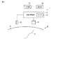
図1は本発明の第1の実施形態に係る散乱体内部計測装置1のブロック構成図である。同図に示すように、散乱体内部計測装置1は、可動性の光照射部10、検出部11、制御/解析部12、メモリ13、表示部14、入力部15を具備している。
Hereinafter, embodiments of the present invention will be described with reference to the drawings. In the following description, components having substantially the same function and configuration are denoted by the same reference numerals, and redundant description will be given only when necessary.
(First embodiment)
FIG. 1 is a block diagram of a scatterer
光照射部10は、散乱体8内部の測定対象7とその周囲の散乱媒質6とで光学特性の異なる光を照射する照明手段である。光照射部には例えばLDなどを用いることができるがこれらに限定されない。この光照射部10から照射される光には、例えば、測定対象には吸収されるが散乱媒質には吸収されない波長の光を使用することができる。光照射部10は、制御/解析部12からの制御信号に基づいて光を散乱体8に向けて照射する。
The
検出部11は、光照射部10によって照射された光が、散乱体8の散乱媒質6と測定対象7により、反射、散乱、吸収され、散乱体表面から出射された後方散乱光強度を検出するものである。本実施形態においては、検出部11に光信号を2次元画像データとして検出できる撮像素子を用いる。例えばCCDを用いることができるがこれに限定されない。検出部11は、制御/解析部12からの制御に基づいて後方散乱光を検出する。
The
上記の光照射部10、検出部11、表示部14及び入力部15は、電気信号が伝送される信号回路によって制御/解析部12に接続される。
The
制御/解析部12は、光照射部10、検出部11の動作を制御すると共に、検出部11によって検出された2次元画像データを解析し、測定対象7が散乱体8の内部に存在しているか否かを確認する。散乱体8の内部に測定対象7が存在している場合、2次元画像データ上での光の照射位置と測定対象7が確認された位置との距離などから、散乱体8において測定対象7が実際に存在する位置や深度が解析される。また制御/解析部12は、検出されたデータを記憶するメモリ13を備える。
The control /
本実施形態においては検出部11として2次元画像データを取得できる撮像素子を用いるが、撮像素子の光学系の画角の観点から、検出部11が散乱体8に接触せずに離れているほうが広い領域を計測できる。そこで、本実施形態における光照射部10及び検出部11は、散乱体に接触せずに一定距離を隔てて照射及び検出を行う。これにより、検出部11は散乱体の広い領域を一度に計測することができる。この検出部11により一度に検出される領域をここでは計測領域と称する。
In the present embodiment, an image pickup device that can acquire two-dimensional image data is used as the
次に、本実施形態に係る散乱体内部計測装置1の作用を説明する。
Next, the operation of the scatterer
図2は本発明に係る散乱体内部計測装置1の動作を表したフローチャートである。S1において、散乱体に光を照射する位置を決定する。S2において、光照射部10により散乱体に光を照射する。S3において、検出部11により、散乱体8内部の散乱媒質6により反射、散乱、吸収され、再度散乱体表面に戻ってきた後方散乱光強度を2次元画像として検出する。検出されたデータはS4においてメモリ13中に記憶される。S5において、測定が終了か否か判断し、終了でなければS1に戻って測定を続ける。終了の場合はS6へ移行する。
FIG. 2 is a flowchart showing the operation of the scatterer
S6において、制御/解析部12がメモリ13に記憶されたデータを解析する。解析結果はS7において表示部14に表示される。S8において計測を終了するか否かを判断し、終了でなければ、S1に戻って計測を続けるかS6に戻って解析を続ける。
In S6, the control /
S6における解析は、以下のような解析手法により行われる。
一つの解析方法として、得られた2次元画像データから、測定対象の位置と深度が解析される。
図3は散乱体内部の光の伝搬の様子を表す概念図である。一般的に散乱体に照射された光は、散乱体内部で散乱を繰り返すうちに散乱の異方性が失われて等方散乱に近づく。この結果、平均的な光経路の断面はバナナ状になることが知られている。
The analysis in S6 is performed by the following analysis method.
As one analysis method, the position and depth of the measurement target are analyzed from the obtained two-dimensional image data.
FIG. 3 is a conceptual diagram showing a state of light propagation inside the scatterer. In general, light irradiated to a scatterer loses its scattering anisotropy while repeating scattering inside the scatterer and approaches isotropic scattering. As a result, it is known that the cross section of the average optical path becomes a banana shape.
図3において、光の照射位置から近い位置I1では散乱体の表面近くを伝搬してきた光が多く検出される。一方、照射位置から離れた位置I2では散乱体のより深部を伝搬してきた光が多く検出される。このように、光の照射位置から検出位置までの距離に応じて、検出された光が伝播してきた深度が変化する。この性質を利用して、測定対象が散乱体内部のいずれの深度に存在するかを解析する。 In FIG. 3, a large amount of light propagating near the surface of the scatterer is detected at a position I 1 close to the light irradiation position. On the other hand, a large amount of light propagating deeper in the scatterer is detected at the position I 2 away from the irradiation position. Thus, the depth at which the detected light has propagated changes according to the distance from the light irradiation position to the detection position. Using this property, it is analyzed at which depth in the scatterer the measurement object exists.
例えば、図3(a)において測定対象は検出位置I1とI2の間の表面近くにある。この場合、検出位置I1とI2における検出光には変化が見られない。一方、図3(b)において測定対象は検出位置I1とI2の間のより深い位置にある。このとき、検出位置I1における検出光には変化が見られないが、検出位置I2における検出光は減弱する。これによって、測定対象の位置と深度が決定される。 For example, in FIG. 3A, the measurement object is near the surface between the detection positions I 1 and I 2 . In this case, no change is seen in the detection light at the detection positions I 1 and I 2 . On the other hand, in FIG. 3B, the measurement object is at a deeper position between the detection positions I 1 and I 2 . At this time, no change is seen in the detection light at the detection position I 1, but the detection light at the detection position I 2 is attenuated. As a result, the position and depth of the measurement target are determined.
このように、2次元画像データ上で後方散乱光強度の弱いポイントが見出された場合、そのポイントと光照射位置との距離を基に解析を行い、深度と位置を算出する。 Thus, when a point with low backscattered light intensity is found on the two-dimensional image data, analysis is performed based on the distance between the point and the light irradiation position, and the depth and position are calculated.
また他の解析方法として、得られた2次元画像データから、一定深度での断層画像が作成される。
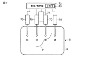
図4に、計測領域で計測される後方散乱光の模式図を示した。光照射部10から散乱体上に光が照射された位置をバツ印で示し、検出部11によって撮像される計測領域40を点線で示した。散乱体8によって反射、散乱、吸収され、散乱体表面から出射された後方散乱光は、図に示すように照射位置を中心とする同心円状になる。ここで、図4(a)に示すように、同心円の直径が大きくなるほど、散乱体のより深部を通ってきた光である。図4(b)においては同心円領域41、42及び43は、それぞれが略同じ深度の情報を有すると見なすことができる。またその深度は照射位置からその同心円までの距離に対応するため、同心円領域41、42及び43の順に深度が深い。よって、2次元画像データから、同心円領域の画像データを抽出することにより、一定の深度における画像データを選択的に取り出すことができ、選択されたデータから該深度での断層画像を作成することができる。
As another analysis method, a tomographic image at a certain depth is created from the obtained two-dimensional image data.
In FIG. 4, the schematic diagram of the backscattered light measured in a measurement area | region was shown. A position where light is irradiated on the scatterer from the
なお、上記の解析方法は、光照射部10の位置を変化させて計測を行うことにより、解析に使用できる情報を簡便により多く取得することができる。
図5は、光照射部10による照射位置を変化させて測定した様子を示す。検出部11は固定されており、計測領域50も移動しない。しかし、光照射部10によって照射する位置を変動させることにより、上述したような同心円領域が移動する。この様子を図6に示す。
Note that the above analysis method can easily acquire more information that can be used for analysis by changing the position of the
FIG. 5 shows a state where measurement is performed by changing the irradiation position by the
図6(a)〜(c)は、同心円領域51、52及び53のそれぞれが移動した軌跡を示す模式図である。それぞれの同心円領域は同じ深度の情報を有している。従って、複数の計測結果を図6に示すように重ね合わせることにより、その深度での断層画像を作成することができる。なお、データを重ね合わせる際に重複する部分が生じるが、重複するデータから任意のデータを選択的に用いるか、重複するデータの平均値を用いればよい。
FIGS. 6A to 6C are schematic diagrams showing the trajectories that the
このように、照射位置を移動させることにより、より多くの情報を簡便に取得することができる。なお、照射位置を移動させる場合、光照射部10が可動可能なように構成される。光照射部10は、それ自体が自由に移動できる構成であってもよく、また或いは光を照射する角度を変動させて照射位置を移動させる構成であってもよい。
Thus, by moving the irradiation position, more information can be easily acquired. In addition, when moving an irradiation position, the
光照射部10のみを移動させることにより、散乱体内部計測装置自体を移動させることなく、複数の2次元画像データを容易に取得することができ、断層画像作成に必要な検出データを効率よく取得することができる。これにより、測定時間を短縮することが出来る。
By moving only the
さらに他の解析方法として、得られた2次元画像データから、所望の位置の任意の深度における情報を得ることができる。 As still another analysis method, information at an arbitrary depth at a desired position can be obtained from the obtained two-dimensional image data.
上述したように、光照射部10の位置を変化させて計測を行うことにより、解析に使用できる多くの情報を容易に取得することができる。さらに、検出されるデータが2次元画像であるため、画像中の所望の位置におけるデータを任意に使用することがきる。従って、上記のように得られた複数の2次元画像データ上で、所望の位置と前記照射位置との間の距離と等しい距離だけ前記所望の位置から離れた位置におけるデータを解析することにより、前記所望の位置の任意の深度における情報を簡便に得ることができる。この場合、情報を得たい深度に応じて、所望の位置と、照射位置並びに解析するデータの位置との距離が決定される。
As described above, by performing measurement while changing the position of the
なお、上述した各解析方法においては、図2のデータ解析工程S6において、照射位置と検出位置との距離を求める際、検出部11の光学系の焦点距離や倍率などを考慮に入れる。さらに、内視鏡などの検出手段で用いられる撮像系の場合、歪曲収差がおこることがある。この場合は、あらかじめ格子チャートなどで歪曲収差の影響の大きさを求めておき、照射位置と検出位置との距離を求める際に考慮に入れる。
In each analysis method described above, when the distance between the irradiation position and the detection position is obtained in the data analysis step S6 of FIG. 2, the focal length and magnification of the optical system of the
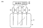
図7〜9は、本第1の実施形態に係る散乱体内部計測装置1の変形例を表すブロック図である。図7は、スポット状の照明光を発する光照射部70が複数備えられた装置である。図8は、ライン状の照明光を発する光照射部80が備えられた装置である。図9は、ライン状の照明光を発する光照射部90が複数備えられた装置である。これらの変形例によれば、一度の測定で多くのデータを検出することができ、測定時間をより短縮することが出来る。なお、ライン状の照明光は光強度が均一であることが好ましい。或いは、光の強度に応じて補正を行う手段を備えることが好ましい。また、光照射部が複数備えられる場合、各光照射部は、それぞれの光によって得られる検出データが互いに干渉しない程度離れた位置に配置される。
7 to 9 are block diagrams illustrating modifications of the scatterer
以上説明したように、本実施形態では、計測されるデータが2次元画像データであるため、照射位置から任意の距離だけ離れた位置のデータを自由に選択することが出来る。それ故、照射位置及び検出位置を設定する際の自由度が高い。また、2次元画像データであるため一度の計測でより多くの情報を取得することができる。その上、散乱体と非接触で計測を行うため、より広い領域を一度に計測することができ、深部の情報も簡便に取得できる。そのため装置を大型化する必要がない。さらに、照射位置及び検出位置の自由度が高いため、所望の位置の任意の深度における情報を容易に得ることができる。 As described above, in this embodiment, since the data to be measured is two-dimensional image data, data at a position separated from the irradiation position by an arbitrary distance can be freely selected. Therefore, the degree of freedom in setting the irradiation position and the detection position is high. Moreover, since it is two-dimensional image data, more information can be acquired by one measurement. In addition, since measurement is performed in a non-contact manner with the scatterer, a wider area can be measured at a time, and deep information can be easily acquired. Therefore, it is not necessary to enlarge the apparatus. Furthermore, since the degree of freedom of the irradiation position and the detection position is high, information at an arbitrary depth at a desired position can be easily obtained.
(第2の実施形態)
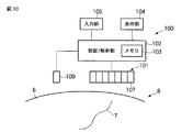
次に、本発明の第2の実施形態を説明する。図10は、第2の実施形態に係る散乱体内部計測装置100のブロック構成図である。本散乱体内部計測装置100においては、光照明部109が可動可能に備えられる。また、検出部101は光検出素子107を複数具備する。光検出素子107は、散乱体8の表面に沿って光照射部109から遠ざかる一方向に沿って配列されてもよく、或いは、散乱体8の表面に沿って二次元マトリックス状に配列されてもよい。
(Second Embodiment)
Next, a second embodiment of the present invention will be described. FIG. 10 is a block configuration diagram of the scatterer
このような第2の実施形態に係る散乱体内部計測装置100によれば、光照射部109を可動させ、所望の位置を中心として、照射位置と対称となる位置にある光検出素子107によって取得されたデータを解析することにより、所望の位置における任意の深度の情報を容易に得ることができる。
According to the scatterer
(第3の実施形態)
次に、本発明の第3の実施形態を説明する。図11は、第3の実施形態に係る散乱体内部計測装置110のブロック構成図である。本散乱体内部計測装置110においては、光照明部119及び検出部120が可動可能に備えられる。
(Third embodiment)
Next, a third embodiment of the present invention will be described. FIG. 11 is a block configuration diagram of the scatterer
このような第3の実施形態に係る散乱体内部計測装置110によれば、光照射部119と検出部120を可動させ、所望の位置を中心として、等距離となる位置にそれぞれを配置する。これにより、所望の位置における任意の深度の情報を得ることができる。得られる情報の深度は、所望の位置と光照射部119及び検出部120との距離を適宜調節することによって容易に変化させることができる。
According to the scatterer
本発明は上記実施形態に限定されるものではなく、その要旨を逸脱しない範囲において様々な変形や変更が可能である。また、上記実施形態に開示されている複数の構成要素を適宜組合せることも可能である。例えば、実施形態に示される全構成要素から幾つかの構成要素を削除してもよい。さらに、異なる実施形態にわたる構成要素を適宜組み合わせてもよい。 The present invention is not limited to the above embodiment, and various modifications and changes can be made without departing from the scope of the invention. In addition, it is possible to appropriately combine a plurality of components disclosed in the embodiment. For example, some components may be deleted from all the components shown in the embodiment. Furthermore, constituent elements over different embodiments may be appropriately combined.
1…散乱体内部計測装置、10…光照射部、11…検出部、12…制御/解析部、13…メモリ、14…表示部、15…入力部。
DESCRIPTION OF
Claims (11)
前記測定対象と前記散乱体とで光学特性の異なる光を前記散乱体に照射する照明手段と、
前記照明手段により照射された光の後方散乱光を2次元画像として検出する検出手段と、
前記検出手段により取得された2次元画像データにおいて前記測定対象の存在の有無を確認し、前記2次元画像上における前記照射位置と前記測定対象が確認された位置との距離から、前記散乱体における前記測定対象の深度を含めた位置情報を求める解析手段とを備え、
前記照明手段と前記検出手段が、前記散乱体に非接触で計測が行われることを特徴とする、散乱体内部計測装置。 A scatterer internal measurement device that acquires information on a measurement target inside a scatterer,
Illuminating means for irradiating the scatterer with light having different optical characteristics between the measurement object and the scatterer;
Detection means for detecting backscattered light of the light irradiated by the illumination means as a two-dimensional image;
In the two-dimensional image data acquired by the detecting means, the presence or absence of the measurement object is confirmed, and the distance between the irradiation position on the two-dimensional image and the position where the measurement object is confirmed is determined in the scatterer. Analyzing means for obtaining position information including the depth of the measurement object,
The scatterer internal measurement device, wherein the illumination unit and the detection unit perform measurement without contact with the scatterer.
前記解析手段による解析結果を表示する表示手段をさらに具備し、
前記解析手段が、前記記憶手段により記憶された複数の2次元画像データを基に、所望の深度における断層画像を作成することを特徴とする、請求項1に記載の散乱体内部計測装置。 Storage means for storing a plurality of two-dimensional image data acquired at a plurality of irradiation positions;
It further comprises display means for displaying the analysis result by the analysis means,
The scatterer internal measurement device according to claim 1, wherein the analysis unit creates a tomographic image at a desired depth based on a plurality of two-dimensional image data stored by the storage unit.
前記測定対象と前記散乱体とで光学特性の異なる光を前記散乱体に照射する可動可能な照明手段と、
前記照明手段により照射された光の後方散乱光を検出する複数の検出手段と、
深度情報を得たい所望の位置を中心として、前記照射位置と対称となる位置にある検出手段によって取得されたデータを解析することにより、前記所望の位置の任意の深度における情報を得る解析手段とを備えることを特徴とする、散乱体内部計測装置。 A scatterer internal measurement device that acquires information on a measurement target inside a scatterer,
Movable illumination means for irradiating the scatterer with light having different optical characteristics between the measurement object and the scatterer;
A plurality of detection means for detecting backscattered light of the light irradiated by the illumination means;
Analyzing means for obtaining information at an arbitrary depth of the desired position by analyzing data acquired by a detecting means at a position symmetrical to the irradiation position with a desired position where depth information is desired as the center; A scatterer internal measurement device comprising:
前記測定対象と前記散乱体とで光学特性の異なる光を前記散乱体に照射する照明手段と、
前記照明手段により照射された光の後方散乱光を検出する検出手段と、
前記検出手段により取得された後方散乱光強度のデータから、所望の位置の任意の深度における情報を得る解析手段とを備え、
前記照明手段と前記検出手段とが、前記所望の位置を中心として等距離に配置されることを特徴とする、散乱体内部計測装置。 A scatterer internal measurement device that acquires information on a measurement target inside a scatterer,
Illuminating means for irradiating the scatterer with light having different optical characteristics between the measurement object and the scatterer;
Detecting means for detecting backscattered light of the light irradiated by the illumination means;
An analysis means for obtaining information at an arbitrary depth at a desired position from the backscattered light intensity data acquired by the detection means;
The scatterer internal measurement device, wherein the illumination unit and the detection unit are arranged at an equal distance with the desired position as a center.
前記測定対象と前記散乱体とで光学特性の異なる光を前記散乱体に照射する工程と、
前記照射された光の後方散乱光を2次元画像として検出する工程と、
前記検出された2次元画像データにおいて前記測定対象の存在の有無を確認し、前記2次元画像上における前記照射位置と前記測定対象が確認された位置との距離から、前記散乱体における前記測定対象の深度を含めた位置情報を求める工程とを含み、
前記光の照射と検出は、前記散乱体に接触せずに行うことを特徴とする方法。 A scatterer internal measurement method for acquiring information on a measurement object inside a scatterer,
Irradiating the scatterer with light having different optical properties between the measurement object and the scatterer;
Detecting backscattered light of the irradiated light as a two-dimensional image;
The presence or absence of the measurement object is confirmed in the detected two-dimensional image data, and the measurement object in the scatterer is determined from the distance between the irradiation position on the two-dimensional image and the position where the measurement object is confirmed. And determining the position information including the depth of
The method of irradiating and detecting the light without contacting the scatterer.
前記記憶された複数の2次元画像データから、前記散乱体内部の所望の深度における断層画像を作成する工程とをさらに含む、請求項7に記載の方法。 Irradiating the scatterer with light at a plurality of different positions and storing a plurality of two-dimensional image data detected for each irradiation position;
The method according to claim 7, further comprising: creating a tomographic image at a desired depth inside the scatterer from the plurality of stored two-dimensional image data.
前記記憶された複数の2次元画像データ上で、所望の位置と前記照射位置との間の距離と等しい距離だけ前記所望の位置から離れた位置におけるデータを解析することにより、前記所望の位置の任意の深度における情報を得る工程をさらに含む、請求項7に記載の方法。 Irradiating the scatterer with light at a plurality of different positions and storing a plurality of two-dimensional image data detected for each irradiation position;
By analyzing data at a position separated from the desired position by a distance equal to the distance between the desired position and the irradiation position on the plurality of stored two-dimensional image data. 8. The method of claim 7, further comprising obtaining information at an arbitrary depth.
前記測定対象と前記散乱体とで光学特性の異なる光を前記散乱体に照射する工程と、
前記照射された光の後方散乱光を複数の検出手段を用いて検出する工程と、
深度情報を得たい所望の位置を中心として、前記照明位置と対称となる位置にある検出手段によって取得されたデータを解析することにより、前記所望の位置の任意の深度における情報を得る工程を含み、
前記照明位置が情報を得たい深度に基づいて決定されることを特徴とする方法。 A scatterer internal measurement method for acquiring information on a measurement object inside a scatterer,
Irradiating the scatterer with light having different optical properties between the measurement object and the scatterer;
Detecting the backscattered light of the irradiated light using a plurality of detection means;
Including the step of obtaining information at an arbitrary depth of the desired position by analyzing the data acquired by the detection means located at a position symmetrical to the illumination position with a desired position where depth information is desired as a center. ,
The method wherein the illumination position is determined based on a depth at which information is desired.
前記測定対象と前記散乱体とで光学特性の異なる光を前記散乱体に照射する工程と、
前記照射された光の後方散乱光を検出する工程と、
前記検出された後方散乱光強度のデータから、所望の位置の任意の深度における情報を得る工程とを含み、
前記照射と前記検出とが、前記所望の位置を中心として等距離で行われ、その中心からの距離が情報を得たい深度に基づいて決定されることを特徴とする方法。 A scatterer internal measurement method for acquiring information on a measurement object inside a scatterer,
Irradiating the scatterer with light having different optical properties between the measurement object and the scatterer;
Detecting backscattered light of the irradiated light;
Obtaining information at an arbitrary depth of a desired position from the detected backscattered light intensity data,
The method according to claim 1, wherein the irradiation and the detection are performed at an equal distance with the desired position as a center, and a distance from the center is determined based on a depth at which information is desired.
Priority Applications (4)
| Application Number | Priority Date | Filing Date | Title |
|---|---|---|---|
| JP2008169459A JP5451991B2 (en) | 2008-06-27 | 2008-06-27 | Scatterer internal measurement device and scatterer internal measurement method |
| PCT/JP2009/055486 WO2009157229A1 (en) | 2008-06-27 | 2009-03-19 | Scatterer interior observation device and scatterer interior observation method |
| US12/978,932 US9055866B2 (en) | 2008-06-27 | 2010-12-27 | Internal observation device for object having light scattering properties, internal body observation device, endoscope for internal observation and internal observation method |
| US14/708,654 US20150238089A1 (en) | 2008-06-27 | 2015-05-11 | Internal observation device for object having light scattering properties, internal body observation device, endoscope for internal observation and internal observation method |
Applications Claiming Priority (1)
| Application Number | Priority Date | Filing Date | Title |
|---|---|---|---|
| JP2008169459A JP5451991B2 (en) | 2008-06-27 | 2008-06-27 | Scatterer internal measurement device and scatterer internal measurement method |
Publications (2)
| Publication Number | Publication Date |
|---|---|
| JP2010008286A true JP2010008286A (en) | 2010-01-14 |
| JP5451991B2 JP5451991B2 (en) | 2014-03-26 |
Family
ID=41588968
Family Applications (1)
| Application Number | Title | Priority Date | Filing Date |
|---|---|---|---|
| JP2008169459A Expired - Fee Related JP5451991B2 (en) | 2008-06-27 | 2008-06-27 | Scatterer internal measurement device and scatterer internal measurement method |
Country Status (1)
| Country | Link |
|---|---|
| JP (1) | JP5451991B2 (en) |
Cited By (2)
| Publication number | Priority date | Publication date | Assignee | Title |
|---|---|---|---|---|
| CN103006228A (en) * | 2012-11-09 | 2013-04-03 | 北京服装学院 | Method for measuring human body morphological characteristics |
| WO2019082594A1 (en) * | 2017-10-25 | 2019-05-02 | パナソニックIpマネジメント株式会社 | Measuring apparatus |
Citations (8)
| Publication number | Priority date | Publication date | Assignee | Title |
|---|---|---|---|---|
| JP2002515277A (en) * | 1998-05-18 | 2002-05-28 | アボット・ラボラトリーズ | Non-invasive optical sensor with control of tissue temperature |
| JP2002531846A (en) * | 1998-12-07 | 2002-09-24 | レア メディツィンテクニック ゲーエムベーハー | Detection probe for depth-resolved optical spectroscopy and spectrometry |
| JP2003010189A (en) * | 2001-07-04 | 2003-01-14 | Communication Research Laboratory | Organism function information imaging device |
| JP2004528542A (en) * | 2001-03-06 | 2004-09-16 | フォーリノーバ、アクティーゼルスカブ | Method and arrangement for measurement of optical properties of multilayer tissue |
| JP2005538752A (en) * | 2002-03-19 | 2005-12-22 | デイヴィッド アール ミラー | Sensor for transcutaneous measurement of vascular access blood flow |
| WO2007105495A1 (en) * | 2006-03-13 | 2007-09-20 | Olympus Medical Systems Corp. | Scattering medium inside observing device, imaging system, imaging method, and endoscope |
| JP2007330381A (en) * | 2006-06-13 | 2007-12-27 | Hitachi Medical Corp | Biological light measuring instrument |
| JP2008510586A (en) * | 2004-08-24 | 2008-04-10 | ザ ジェネラル ホスピタル コーポレイション | Method and apparatus for imaging blood vessel segments |
-
2008
- 2008-06-27 JP JP2008169459A patent/JP5451991B2/en not_active Expired - Fee Related
Patent Citations (8)
| Publication number | Priority date | Publication date | Assignee | Title |
|---|---|---|---|---|
| JP2002515277A (en) * | 1998-05-18 | 2002-05-28 | アボット・ラボラトリーズ | Non-invasive optical sensor with control of tissue temperature |
| JP2002531846A (en) * | 1998-12-07 | 2002-09-24 | レア メディツィンテクニック ゲーエムベーハー | Detection probe for depth-resolved optical spectroscopy and spectrometry |
| JP2004528542A (en) * | 2001-03-06 | 2004-09-16 | フォーリノーバ、アクティーゼルスカブ | Method and arrangement for measurement of optical properties of multilayer tissue |
| JP2003010189A (en) * | 2001-07-04 | 2003-01-14 | Communication Research Laboratory | Organism function information imaging device |
| JP2005538752A (en) * | 2002-03-19 | 2005-12-22 | デイヴィッド アール ミラー | Sensor for transcutaneous measurement of vascular access blood flow |
| JP2008510586A (en) * | 2004-08-24 | 2008-04-10 | ザ ジェネラル ホスピタル コーポレイション | Method and apparatus for imaging blood vessel segments |
| WO2007105495A1 (en) * | 2006-03-13 | 2007-09-20 | Olympus Medical Systems Corp. | Scattering medium inside observing device, imaging system, imaging method, and endoscope |
| JP2007330381A (en) * | 2006-06-13 | 2007-12-27 | Hitachi Medical Corp | Biological light measuring instrument |
Cited By (2)
| Publication number | Priority date | Publication date | Assignee | Title |
|---|---|---|---|---|
| CN103006228A (en) * | 2012-11-09 | 2013-04-03 | 北京服装学院 | Method for measuring human body morphological characteristics |
| WO2019082594A1 (en) * | 2017-10-25 | 2019-05-02 | パナソニックIpマネジメント株式会社 | Measuring apparatus |
Also Published As
| Publication number | Publication date |
|---|---|
| JP5451991B2 (en) | 2014-03-26 |
Similar Documents
| Publication | Publication Date | Title |
|---|---|---|
| JP5684443B2 (en) | Biological component measuring device | |
| US20160150968A1 (en) | Object information acquiring apparatus | |
| EP2868263B1 (en) | Photoacoustic mammography apparatus and method | |
| US20180256065A1 (en) | Multiple optical fusion-image based method and apparatus for diagnosing brain tumor in real-time | |
| JP2010508105A (en) | Retina diagnosis method and apparatus | |
| WO2015162899A1 (en) | Photoacoustic apparatus, method of controlling photoacoustic apparatus, and program | |
| JP6745889B2 (en) | Photoacoustic image generator | |
| US9200886B2 (en) | Method and system for optical coherence tomography | |
| WO2009157229A1 (en) | Scatterer interior observation device and scatterer interior observation method | |
| US20160058295A1 (en) | Photoacoustic wave measurement apparatus and photoacoustic wave measurement method | |
| JP5451991B2 (en) | Scatterer internal measurement device and scatterer internal measurement method | |
| JP6486085B2 (en) | Photoacoustic wave measuring device | |
| US9551565B2 (en) | Method and system for optical coherence tomography including obtaining at least two two-dimensional images of an object in three-dimensional space | |
| JP2009148388A (en) | Optical measuring device | |
| JP2017529913A (en) | Photoacoustic device | |
| US20170086679A1 (en) | Photoacoustic apparatus and method for acquiring object information | |
| JP2010223770A (en) | Scatterer inside observation device, and scatterer inside observation method | |
| JP2009005721A (en) | Pulse wave measuring method and pulse wave measuring apparatus used for it | |
| JP6628891B2 (en) | Photoacoustic image generation device | |
| US20180149464A1 (en) | Automated optical coherence tomography scanning | |
| EP3329843A1 (en) | Display control apparatus, display control method, and program | |
| JP2021014988A (en) | Measurement device | |
| JP5188909B2 (en) | Scatterer internal observation device and scatterer internal observation method | |
| JP2007085775A (en) | Sample analyzer | |
| US20200085345A1 (en) | Object information acquisition apparatus and method of controlling the same |
Legal Events
| Date | Code | Title | Description |
|---|---|---|---|
| A621 | Written request for application examination |
Free format text: JAPANESE INTERMEDIATE CODE: A621 Effective date: 20110613 |
|
| A131 | Notification of reasons for refusal |
Free format text: JAPANESE INTERMEDIATE CODE: A131 Effective date: 20130409 |
|
| A521 | Request for written amendment filed |
Free format text: JAPANESE INTERMEDIATE CODE: A523 Effective date: 20130610 |
|
| TRDD | Decision of grant or rejection written | ||
| A01 | Written decision to grant a patent or to grant a registration (utility model) |
Free format text: JAPANESE INTERMEDIATE CODE: A01 Effective date: 20131210 |
|
| A61 | First payment of annual fees (during grant procedure) |
Free format text: JAPANESE INTERMEDIATE CODE: A61 Effective date: 20131227 |
|
| R151 | Written notification of patent or utility model registration |
Ref document number: 5451991 Country of ref document: JP Free format text: JAPANESE INTERMEDIATE CODE: R151 |
|
| S531 | Written request for registration of change of domicile |
Free format text: JAPANESE INTERMEDIATE CODE: R313531 |
|
| R350 | Written notification of registration of transfer |
Free format text: JAPANESE INTERMEDIATE CODE: R350 |
|
| R250 | Receipt of annual fees |
Free format text: JAPANESE INTERMEDIATE CODE: R250 |
|
| LAPS | Cancellation because of no payment of annual fees |