JP2010007997A - Refrigerant amount determining method of air conditioning device, and air conditioning device - Google Patents
Refrigerant amount determining method of air conditioning device, and air conditioning device Download PDFInfo
- Publication number
- JP2010007997A JP2010007997A JP2008169598A JP2008169598A JP2010007997A JP 2010007997 A JP2010007997 A JP 2010007997A JP 2008169598 A JP2008169598 A JP 2008169598A JP 2008169598 A JP2008169598 A JP 2008169598A JP 2010007997 A JP2010007997 A JP 2010007997A
- Authority
- JP
- Japan
- Prior art keywords
- refrigerant
- condition
- heat exchanger
- range
- degree
- Prior art date
- Legal status (The legal status is an assumption and is not a legal conclusion. Google has not performed a legal analysis and makes no representation as to the accuracy of the status listed.)
- Granted
Links
Images


Abstract
Description
本発明は、空気調和装置の冷媒回路内に充填されている冷媒量の適否を判定する機能、特に、熱源ユニットと利用ユニットとが冷媒連絡配管を介して接続された空気調和装置の冷媒回路内に充填されている冷媒量の適否を判定する機能に関する。 The present invention relates to a function for determining the suitability of the amount of refrigerant charged in the refrigerant circuit of the air conditioner, in particular, in the refrigerant circuit of the air conditioner in which the heat source unit and the utilization unit are connected via a refrigerant communication pipe. It is related with the function which determines the suitability of the refrigerant | coolant amount with which it filled.
従来、凝縮器の過冷却度にもとづいて冷媒量を判定する冷媒量判定運転のような試運転を行う空気調和装置がある(特許文献1参照)。
しかしながら、特許文献1に記載されているような空気調和装置において、外気温度などの環境条件が異なる場合には、冷媒量判定運転が同じ条件下で行われていないことになり、検知誤差になる可能性がある。
However, in the air conditioner described in
本発明の課題は、できるだけ検知誤差が出ないような条件下で冷媒量判定運転を行う空気調和装置の冷媒量判定方法およびそれを実現した空気調和装置を提供することにある。 The subject of this invention is providing the refrigerant | coolant amount determination method of the air conditioning apparatus which performs refrigerant | coolant amount determination driving | running conditions on the conditions which a detection error does not occur as much as possible, and the air conditioning apparatus which implement | achieved it.
第1発明に係る空気調和装置の冷媒量判定方法は、運転容量を調節可能な圧縮機と熱源側熱交換器とを有する熱源ユニットと、利用側熱交換器を有する利用ユニットと、膨張機構と、熱源ユニットと利用ユニットとを接続する液冷媒連絡配管およびガス冷媒連絡配管とを含み、熱源側熱交換器を圧縮機において圧縮される冷媒の凝縮器として、かつ、利用側熱交換器を熱源側熱交換器において凝縮される冷媒の蒸発器として機能させる冷房運転を少なくとも行うことが可能な冷媒回路を有する空気調和装置において、冷媒回路内の冷媒量の適否を判定する冷媒量判定方法であって、初期運転ステップと、記憶ステップと、条件判定ステップとを備える。初期運転ステップでは、利用ユニットの運転負荷に応じて熱源ユニットおよび利用ユニットの各機器の制御を行う通常運転モードから、前期冷房運転し利用側熱交換器の出口における冷媒の過熱度が正値になるように膨張機構を制御しつつ熱源側熱交換器の出口における冷媒の過冷却度または過冷却度の変動に応じて変動する運転状態量を検出して、過冷却度が第1所定値以上に、または、運転状態量が第2所定値以上にした安定状態にする。記憶ステップでは、安定状態における圧縮機の周波数を第1周波数として、安定状態における利用側熱交換器の出口の冷媒の過熱度を第1過熱度として、安定状態における過冷却度または運転状態量を指標値として、初期運転ステップにおける環境条件を第1条件として記憶する。条件判定ステップでは、記憶ステップから所定期間経過後の環境条件が第1条件に基づいて換算される範囲である第1条件範囲内にある場合に、記憶ステップにより記憶された第1周波数になるように圧縮機の制御を行い、かつ、第1過熱度になるように膨張機構の制御を行いつつ熱源側熱交換器の出口における冷媒の過冷却度または過冷却度の変動に応じて変動する運転状態量を検出値として検出して、指標値と検出値とを比較して、冷媒回路内に充填されている冷媒量の適否を判定する冷媒量適否判定を行い、記憶ステップから所定期間経過後の環境条件が第1条件範囲内にない場合に、冷媒量適否判定を行わない、冷媒量適否判定を行うべき適切な条件ではないことを報告する、冷媒量適否判定を行うべき適切な条件を報告する、のうちの少なくとも1つを冷媒量適否不可制御として行う。 A refrigerant amount determination method for an air conditioner according to a first aspect of the present invention includes a heat source unit having a compressor capable of adjusting an operating capacity and a heat source side heat exchanger, a utilization unit having a utilization side heat exchanger, an expansion mechanism, A liquid refrigerant communication pipe and a gas refrigerant communication pipe connecting the heat source unit and the utilization unit, the heat source side heat exchanger as a refrigerant condenser to be compressed in the compressor, and the utilization side heat exchanger as the heat source In the air conditioner having a refrigerant circuit capable of performing at least a cooling operation for functioning as an evaporator of refrigerant condensed in the side heat exchanger, a refrigerant amount determination method for determining suitability of the refrigerant amount in the refrigerant circuit. And an initial operation step, a storage step, and a condition determination step. In the initial operation step, from the normal operation mode in which the heat source unit and each device of the utilization unit are controlled according to the operation load of the utilization unit, the refrigerant superheat degree at the outlet of the utilization side heat exchanger is positive after the previous cooling operation. While controlling the expansion mechanism to detect, the degree of supercooling of the refrigerant at the outlet of the heat source side heat exchanger or the fluctuation in the degree of supercooling is detected, and the degree of supercooling is greater than or equal to the first predetermined value Alternatively, a stable state in which the operating state quantity is equal to or greater than the second predetermined value is set. In the storage step, the compressor frequency in the stable state is set as the first frequency, the superheat degree of the refrigerant at the outlet of the use side heat exchanger in the stable state is set as the first superheat degree, and the degree of supercooling or the operating state quantity in the stable state is calculated. As the index value, the environmental condition in the initial operation step is stored as the first condition. In the condition determining step, the first frequency stored in the storing step is set when the environmental condition after the lapse of a predetermined period from the storing step is within a first condition range that is a range converted based on the first condition. In which the compressor is controlled and the expansion mechanism is controlled so that the first superheat degree is reached, and the refrigerant is subcooled at the outlet of the heat source side heat exchanger, or the operation fluctuates according to the fluctuation of the supercooling degree. The state quantity is detected as a detected value, the index value is compared with the detected value, and the refrigerant quantity is determined to be appropriate to determine the appropriateness of the refrigerant quantity charged in the refrigerant circuit. When the environmental condition is not within the first condition range, the refrigerant amount suitability determination is not performed, and it is reported that the refrigerant amount suitability determination is not an appropriate condition. Report, no Performing a refrigerant quantity adequacy Call control at least one of.
本発明の冷媒量判定方法では、熱源ユニットと利用ユニットとが冷媒連絡配管を介して接続されて冷媒回路を構成しており、少なくとも冷房運転が可能なセパレートタイプの空気調和装置においてなされる方法である。ここで、「少なくとも」としたのは、本発明が適用可能な空気調和装置として、冷房運転以外に暖房運転等の別の運転も行うことが可能なものが含まれるからである。そして、この空気調和装置では、冷房運転等の通常運転(以下、通常運転モードとする)と、利用ユニットを強制的に冷房運転させる冷媒量判定運転モードとを切り換えて運転することが可能になっており、熱源側熱交換器の出口における冷媒の過冷却度または過冷却度の変動に応じて変動する運転状態量を検出して冷媒回路内に充填されている冷媒量の適否を判定することができる。 In the refrigerant amount determination method of the present invention, the heat source unit and the utilization unit are connected via a refrigerant communication pipe to form a refrigerant circuit, and the method is performed in a separate type air conditioner capable of at least cooling operation. is there. Here, “at least” is because the air conditioner to which the present invention can be applied includes one that can perform another operation such as a heating operation in addition to the cooling operation. In this air conditioner, it is possible to switch between a normal operation such as a cooling operation (hereinafter referred to as a normal operation mode) and a refrigerant amount determination operation mode in which the use unit is forcibly cooled. Detecting the degree of refrigerant subcooling at the outlet of the heat source side heat exchanger or the amount of operating state that fluctuates in accordance with the fluctuation of the degree of supercooling and determining the suitability of the refrigerant amount charged in the refrigerant circuit Can do.
このように冷媒量の適否を判定する空気調和装置の冷媒量判定方法において、記憶ステップから所定期間経過後の環境条件が第1条件に基づいて換算される範囲である第1条件範囲内にある場合に、記憶ステップにより記憶された第1周波数になるように圧縮機の制御を行い、かつ、第1過熱度になるように膨張機構の制御を行いつつ熱源側熱交換器の出口における冷媒の過冷却度または過冷却度の変動に応じて変動する運転状態量を検出値として検出して、指標値と検出値とを比較して、冷媒回路内に充填されている冷媒量の適否を判定する冷媒量適否判定を行い、記憶ステップから所定期間経過後の環境条件が第1条件範囲内にない場合に、冷媒量適否判定を行わない、冷媒量適否判定を行うべき適切な条件ではないことを報告する、冷媒量適否判定を行うべき適切な条件を報告する、のうちの少なくとも1つを冷媒量適否不可制御として行う。 Thus, in the refrigerant amount determination method of the air conditioner that determines the suitability of the refrigerant amount, the environmental condition after the elapse of a predetermined period from the storing step is within a first condition range that is a range converted based on the first condition. In this case, the compressor is controlled so as to have the first frequency stored in the storing step, and the expansion mechanism is controlled so as to become the first superheat degree, and the refrigerant at the outlet of the heat source side heat exchanger is controlled. The degree of supercooling or the amount of operating state that varies according to the degree of supercooling is detected as a detected value, and the index value is compared with the detected value to determine whether the refrigerant amount charged in the refrigerant circuit is appropriate. The refrigerant amount suitability determination is performed, and when the environmental condition after the lapse of a predetermined period from the storage step is not within the first condition range, the refrigerant amount suitability determination is not performed, and the refrigerant amount suitability determination is not an appropriate condition. To report, cold Report the appropriate conditions to carry out the amount appropriateness determination, performed as the refrigerant quantity adequacy Call control at least one of.
したがって、できるだけ検知誤差が発生しないような環境条件の範囲内において、冷媒量の適否の判定を行うことができるため、検知誤差を少なくできる。また、検知誤差が発生する環境条件の範囲内であることを認識すると、冷媒量適否判定を行わない、冷媒量適否判定を行うべき適切な条件ではないことを利用者に報告する、冷媒量適否判定を行うべき適切な条件を報告する、のうちの少なくとも1つを冷媒量適否不可制御として行うため、冷媒量適否判定ができなくとも利用者は冷媒量適否判定ができるように対策を講じることができるため、検知誤差が少ない条件において冷媒量適否判定をできるようにさせることができる。 Therefore, the suitability of the refrigerant amount can be determined within the range of environmental conditions where detection errors do not occur as much as possible, so that detection errors can be reduced. Also, if it is recognized that the detection error is within the range of environmental conditions, the refrigerant amount propriety determination is not performed, and the refrigerant amount propriety is reported to the user that the refrigerant amount propriety determination is not appropriate. Since at least one of reporting appropriate conditions to be judged is controlled as refrigerant quantity propriety control, measures should be taken so that the user can judge the refrigerant quantity suitability even if the refrigerant quantity suitability cannot be judged. Therefore, it is possible to determine whether or not the refrigerant amount is appropriate under the condition that the detection error is small.
第2発明に係る空気調和装置の冷媒量判定方法は、第1発明に係る空気調和装置の冷媒量判定方法であって、環境条件は、外気温度、暦に基づく外気温度、外部から取得される天候条件の少なくとも1つを含む。 A refrigerant amount determination method for an air conditioner according to a second aspect of the present invention is the refrigerant amount determination method for an air conditioner according to the first aspect of the present invention, wherein the environmental conditions are acquired from the outside temperature, the outside temperature based on the calendar, and the outside. Including at least one of the weather conditions.
本発明では、環境条件は、外気温度、暦の基づく外気温度、外部から取得される天候条件の少なくとも1つが採用される。したがって、各環境条件に応じて柔軟に冷媒量適否判定が可能か否かを判定することが可能になる。 In the present invention, as the environmental condition, at least one of an outside temperature, an outside temperature based on a calendar, and a weather condition acquired from the outside is employed. Therefore, it is possible to flexibly determine whether or not the refrigerant amount suitability can be determined according to each environmental condition.
第3発明に係る空気調和装置の冷媒量判定方法は、第1発明または第2発明に係る空気調和装置の冷媒量判定方法であって、第1条件は、外気温度を少なくとも含む。第1条件範囲は、外気温度に基づいて、その範囲の幅である第1範囲幅が決定される。第1範囲幅は、外気温度と正の相関関係にある。 A refrigerant amount determination method for an air conditioner according to a third aspect of the present invention is the refrigerant amount determination method for an air conditioner according to the first or second aspect of the present invention, wherein the first condition includes at least an outside air temperature. In the first condition range, a first range width that is the width of the range is determined based on the outside air temperature. The first range width has a positive correlation with the outside air temperature.
外気温度が増加するに従って過冷却度または運転状態量の変化量も増加する傾向にある。さらに、例えば、冷媒回路内の冷媒量が100%から90%に10%減少したことを検知するための冷媒漏洩検知用の過冷却度または運転状態量の変化量のマージンを確保すると、外気温度が低い場合よりも外気温度が高い場合の冷媒量を適否可能な検知範囲が大きいことから、外気温度が大きくなると冷媒量の変化を検知可能な外気温度の範囲が広がる。 As the outside air temperature increases, the amount of change in the degree of supercooling or the amount of operating state tends to increase. Further, for example, when a margin for the amount of change in the degree of subcooling or the amount of operating state for detecting refrigerant leakage is detected to detect that the amount of refrigerant in the refrigerant circuit has decreased by 10% from 100% to 90%, the outside air temperature Since the detection range in which the refrigerant amount when the outside air temperature is higher than that when the outside air temperature is high is large, the range of the outside air temperature where the change in the refrigerant amount can be detected increases as the outside air temperature increases.
したがって、本発明のように、第1範囲幅と外気温度とが正の相関関係にあるように外気温度に基づいて第1範囲幅を決定することにより、例えば、外気温度と第1温度範囲を決定するための第1範囲幅とを関連づけたデータをあらかじめ記憶しておき、そのデータに基づいて第1温度範囲を決定するようにすると、精度よく冷媒量の適否の判定を行うことが可能となる。 Therefore, as in the present invention, by determining the first range width based on the outside air temperature so that the first range width and the outside air temperature have a positive correlation, for example, the outside air temperature and the first temperature range are By storing in advance data associated with the first range width for determination and determining the first temperature range based on the data, it is possible to accurately determine whether the refrigerant amount is appropriate. Become.
第4発明に係る空気調和装置の冷媒量判定方法は、第1発明から第3発明のいずれかに係る空気調和装置の冷媒量判定方法であって、条件判定ステップは、記憶ステップから所定期間経過後に定期的に行われる。そして、条件判定ステップにおいて、記憶ステップから所定期間経過後の環境条件が第1条件範囲内にある場合に、その時の環境条件を第2環境条件として記憶し、第2環境条件に基づいて換算される範囲である第2条件範囲を導出し、次回行われる条件判定ステップにおいて、第1条件範囲と第2条件範囲とを加えた拡大条件範囲内にその時の環境条件がある場合には冷媒量適否判定を行い、第1条件範囲と第2条件範囲とを加えた拡大条件範囲内にその時の環境条件がない場合には冷媒量適否不可制御を行う。 A refrigerant amount determination method for an air conditioner according to a fourth aspect of the present invention is the refrigerant amount determination method for an air conditioner according to any one of the first to third aspects of the invention, wherein the condition determination step is a lapse of a predetermined period from the storage step. It will be done regularly later. Then, in the condition determining step, when the environmental condition after the lapse of a predetermined period from the storing step is within the first condition range, the environmental condition at that time is stored as the second environmental condition and converted based on the second environmental condition. The second condition range is derived, and in the next condition determination step, if the environmental condition at that time is within the expanded condition range including the first condition range and the second condition range, the refrigerant amount is appropriate. When the environmental condition at that time is not within the expanded condition range obtained by adding the first condition range and the second condition range, the refrigerant amount propriety control is performed.
本発明では、条件判定ステップの際の基準となる第1条件範囲が、記憶ステップから所定期間経過後に定期的に行われる条件判定ステップにおいて検出される環境条件が第1条件範囲内にある場合に、その時の環境条件に基づいて第2環境条件範囲がさらに導出され、次回以降行われる条件判定ステップにおいて、第1条件範囲と第2条件範囲とを加えた拡大条件範囲内に、その時の環境条件がある場合には冷媒量適否判定が行われ、その時の環境条件がない場合には冷媒適否不可制御が行われる。なお、冷媒量適否判定が行われる場合には、拡大条件範囲内のうちでその時の環境条件を含んでいる条件範囲の基になる環境条件下における過冷却度または運転状態量が冷媒量の適否の判定においての指標値となる。 In the present invention, when the first condition range serving as a reference in the condition determining step is within the first condition range, the environmental condition detected in the condition determining step periodically performed after the lapse of a predetermined period from the storing step. The second environmental condition range is further derived based on the environmental condition at that time, and in the condition determination step performed next time, the environmental condition at that time is within the expanded condition range obtained by adding the first condition range and the second condition range. If there is, the refrigerant amount suitability determination is performed, and if there is no environmental condition at that time, the refrigerant suitability disabling control is performed. In addition, when the refrigerant amount suitability determination is performed, the degree of supercooling or the operating state amount under the environmental condition that is the basis of the condition range including the environmental condition at that time within the expanded condition range is appropriate for the refrigerant amount. It becomes an index value in the determination.
したがって、初期運転ステップ以降において2回目以降の条件判定ステップにおいて、全てのステップで環境条件が冷媒量適否判定を行うべき温度範囲内にあった場合に、冷媒量適否判定を行うべき温度範囲内にあった環境条件に基づいて新たに温度範囲が追加されることになり、これらの情報を蓄積していくことにより、様々な環境条件下においても冷媒量適否判定を行うことができるようになり、効率よく冷媒量適否判定をおこなうことができる。 Accordingly, in the second and subsequent condition determination steps after the initial operation step, if the environmental conditions are within the temperature range in which the refrigerant amount suitability determination is to be performed in all steps, the refrigerant amount suitability determination is in the temperature range in which the refrigerant amount suitability determination is to be performed. A new temperature range will be added based on the environmental conditions that exist, and by accumulating such information, it will be possible to determine the suitability of the refrigerant amount under various environmental conditions, It is possible to efficiently determine the suitability of the refrigerant amount.
第5発明に係る空気調和装置の冷媒量判定方法は、第3発明に係る空気調和装置の冷媒量判定方法であって、第2条件は、外気温度を少なくとも含む。第2条件範囲は、外気温度に基づいて、その範囲の幅である第2範囲幅が決定される。第2範囲幅は、外気温度と正の相関関係にある。 A refrigerant amount determination method for an air conditioner according to a fifth aspect of the present invention is the refrigerant amount determination method for an air conditioner according to the third aspect of the present invention, wherein the second condition includes at least an outside air temperature. In the second condition range, a second range width that is the width of the range is determined based on the outside air temperature. The second range width has a positive correlation with the outside air temperature.
外気温度が増加するに従って過冷却度または運転状態量の変化量も増加する傾向にある。さらに、例えば、冷媒回路内の冷媒量が100%から90%に10%減少したことを検知するための冷媒漏洩検知用の過冷却度または運転状態量の変化量のマージンを確保すると、外気温度が低い場合よりも外気温度が高い場合の冷媒量を適否可能な検知範囲が大きいことから、外気温度が大きくなると冷媒量の変化を検知可能な外気温度の範囲が広がる。 As the outside air temperature increases, the amount of change in the degree of supercooling or the amount of operating state tends to increase. Further, for example, when a margin for the amount of change in the degree of subcooling or the amount of operating state for detecting refrigerant leakage is detected to detect that the amount of refrigerant in the refrigerant circuit has decreased by 10% from 100% to 90%, the outside air temperature Since the detection range in which the refrigerant amount when the outside air temperature is higher than that when the outside air temperature is high is large, the range of the outside air temperature where the change in the refrigerant amount can be detected increases as the outside air temperature increases.
したがって、本発明のように、第2範囲幅と外気温度とが正の相関関係にあるように外気温度に基づいて第2範囲幅を決定することにより、例えば、外気温度と第2温度範囲を決定するための第2範囲幅とを関連づけたデータをあらかじめ記憶しておき、そのデータに基づいて第2温度範囲を決定するようにすると、精度よく冷媒量の適否の判定を行うことが可能となる。 Accordingly, as in the present invention, by determining the second range width based on the outside air temperature so that the second range width and the outside air temperature have a positive correlation, for example, the outside air temperature and the second temperature range can be determined. If data relating to the second range width for determination is stored in advance and the second temperature range is determined based on the data, it is possible to accurately determine whether the refrigerant amount is appropriate. Become.
第6発明に係る空気調和装置は、冷媒回路と、初期運転手段と、記憶手段と、条件判定手段とを備える。冷媒回路は、熱源ユニットと、利用ユニットと、膨張機構と、液冷媒連絡配管およびガス冷媒連絡配管とを含む。熱源ユニットは、運転容量を調節可能な圧縮機と熱源側熱交換器とを有する。利用ユニットは、利用側熱交換器を有する。液冷媒連絡配管およびガス冷媒連絡配管は、熱源ユニットと利用ユニットとを接続する。また、冷媒回路は、熱源側熱交換器を圧縮機において圧縮される冷媒の凝縮器として、かつ、利用側熱交換器を熱源側熱交換器において凝縮される冷媒の蒸発器として機能させる冷房運転を少なくとも行うことが可能である。そして、初期運転手段は、利用ユニットの運転負荷に応じて熱源ユニットおよび利用ユニットの各機器の制御を行う通常運転モードから、前期冷房運転し利用側熱交換器の出口における冷媒の過熱度が正値になるように膨張機構を制御しつつ熱源側熱交換器の出口における冷媒の過冷却度または過冷却度の変動に応じて変動する運転状態量を検出して、過冷却度が第1所定値以上に、または、運転状態量が第2所定値以上にした安定状態にする。記憶手段は、安定状態における圧縮機の周波数を第1周波数として、安定状態における利用側熱交換器の出口の冷媒の過熱度を第1過熱度として、安定状態における過冷却度または運転状態量を指標値として、初期運転ステップにおける環境条件を第1条件として記憶する。条件判定手段は、記憶ステップから所定期間経過後の環境条件が第1条件に基づいて換算される範囲である第1条件範囲内にある場合に、記憶ステップにより記憶された第1周波数になるように圧縮機の制御を行い、かつ、第1過熱度になるように膨張機構の制御を行いつつ熱源側熱交換器の出口における冷媒の過冷却度または過冷却度の変動に応じて変動する運転状態量を検出値として検出して、指標値と検出値とを比較して、冷媒回路内に充填されている冷媒量の適否を判定する冷媒量適否判定を行い、記憶ステップから所定期間経過後の環境条件が第1条件範囲内にない場合に、冷媒量適否判定を行わない、冷媒量適否判定を行うべき適切な条件ではないことを報告する、冷媒量適否判定を行うべき適切な条件を報告する、のうちの少なくとも1つ冷媒量適否不可制御として行う。 An air conditioner according to a sixth aspect of the present invention includes a refrigerant circuit, initial operation means, storage means, and condition determination means. The refrigerant circuit includes a heat source unit, a utilization unit, an expansion mechanism, a liquid refrigerant communication pipe and a gas refrigerant communication pipe. The heat source unit includes a compressor capable of adjusting an operation capacity and a heat source side heat exchanger. The utilization unit has a utilization side heat exchanger. The liquid refrigerant communication pipe and the gas refrigerant communication pipe connect the heat source unit and the utilization unit. Further, the refrigerant circuit is a cooling operation in which the heat source side heat exchanger functions as a condenser for refrigerant compressed in the compressor, and the use side heat exchanger functions as an evaporator for refrigerant condensed in the heat source side heat exchanger. Can be performed at least. Then, the initial operation means starts from the normal operation mode in which the heat source unit and each device of the utilization unit are controlled in accordance with the operation load of the utilization unit, and the refrigerant is superheated at the outlet of the utilization side heat exchanger in the previous cooling operation. While controlling the expansion mechanism to be a value, the degree of subcooling of the refrigerant at the outlet of the heat source side heat exchanger or the amount of operating state that fluctuates according to the fluctuation of the degree of subcooling is detected, and the degree of subcooling is a first predetermined value. Or a stable state in which the operating state quantity is equal to or greater than the second predetermined value. The storage means uses the compressor frequency in the stable state as the first frequency, sets the superheat degree of the refrigerant at the outlet of the use side heat exchanger in the stable state as the first superheat degree, and determines the degree of supercooling or the operating state quantity in the stable state. As the index value, the environmental condition in the initial operation step is stored as the first condition. The condition determination means has the first frequency stored in the storage step when the environmental condition after a predetermined period has elapsed from the storage step is within a first condition range that is a range converted based on the first condition. In which the compressor is controlled and the expansion mechanism is controlled so that the first superheat degree is reached, and the refrigerant is subcooled at the outlet of the heat source side heat exchanger, or the operation fluctuates according to the fluctuation of the supercooling degree. The state quantity is detected as a detected value, the index value is compared with the detected value, and the refrigerant quantity is determined to be appropriate to determine the appropriateness of the refrigerant quantity charged in the refrigerant circuit. When the environmental condition is not within the first condition range, the refrigerant amount suitability determination is not performed, and it is reported that the refrigerant amount suitability determination is not an appropriate condition. To report Kutomo performed as one refrigerant quantity adequacy not control.
したがって、できるだけ検知誤差が発生しないような環境条件の範囲内において、冷媒量の適否の判定を行うことができるため、検知誤差を少なくできる。また、検知誤差が発生する環境条件の範囲内であることを認識すると、冷媒量適否判定を行わない、冷媒量適否判定を行うべき適切な条件ではないことを利用者に報告する、冷媒量適否判定を行うべき適切な条件を報告する、のうちの少なくとも1つを冷媒量適否不可制御として行うため、冷媒量適否判定ができなくとも利用者は冷媒量適否判定ができるように対策を講じることができるため、検知誤差が少ない条件において冷媒量適否判定をできるようにさせることができる。 Therefore, the suitability of the refrigerant amount can be determined within the range of environmental conditions where detection errors do not occur as much as possible, so that detection errors can be reduced. Also, if it is recognized that the detection error is within the range of environmental conditions, the refrigerant amount propriety determination is not performed, and the refrigerant amount propriety is reported to the user that the refrigerant amount propriety determination is not appropriate. Since at least one of reporting appropriate conditions to be judged is controlled as refrigerant quantity propriety control, measures should be taken so that the user can judge the refrigerant quantity suitability even if the refrigerant quantity suitability cannot be judged. Therefore, it is possible to determine whether or not the refrigerant amount is appropriate under the condition that the detection error is small.
第1発明に係る空気調和装置の冷媒量判定方法では、できるだけ検知誤差が発生しないような環境条件の範囲内において、冷媒量の適否の判定を行うことができるため、検知誤差を少なくできる。また、検知誤差が発生する環境条件の範囲内であることを認識すると、冷媒量適否判定を行わない、冷媒量適否判定を行うべき適切な条件ではないことを利用者に報告する、冷媒量適否判定を行うべき適切な条件を報告する、のうちの少なくとも1つを冷媒量適否不可制御として行うため、冷媒量適否判定ができなくとも利用者は冷媒量適否判定ができるように対策を講じることができるため、検知誤差が少ない条件において冷媒量適否判定をできるようにさせることができる。 In the refrigerant quantity determination method for an air conditioner according to the first aspect of the invention, it is possible to determine the suitability of the refrigerant quantity within a range of environmental conditions where detection errors do not occur as much as possible. Also, if it is recognized that the detection error is within the range of environmental conditions, the refrigerant amount propriety determination is not performed, and the refrigerant amount propriety is reported to the user that the refrigerant amount propriety determination is not appropriate. Since at least one of reporting appropriate conditions to be judged is controlled as refrigerant quantity propriety control, measures should be taken so that the user can judge the refrigerant quantity suitability even if the refrigerant quantity suitability cannot be judged. Therefore, it is possible to determine whether or not the refrigerant amount is appropriate under the condition that the detection error is small.
第2発明に係る空気調和装置の冷媒量判定方法では、各環境条件に応じて柔軟に冷媒量適否判定が可能か否かを判定することが可能になる。 In the refrigerant amount determination method for the air conditioner according to the second aspect of the present invention, it is possible to determine whether or not the refrigerant amount suitability can be flexibly determined according to each environmental condition.
第3発明に係る空気調和装置の冷媒量判定方法では、第1範囲幅と外気温度とが正の相関関係にあるように外気温度に基づいて第1範囲幅を決定することにより、例えば、外気温度と第1温度範囲を決定するための第1範囲幅とを関連づけたデータをあらかじめ記憶しておき、そのデータに基づいて第1温度範囲を決定するようにすると、精度よく冷媒量の適否の判定を行うことが可能となる。 In the refrigerant amount determination method for the air conditioner according to the third aspect of the invention, the first range width is determined based on the outside air temperature so that the first range width and the outside air temperature have a positive correlation, for example, outside air. If data that associates the temperature with the first range for determining the first temperature range is stored in advance, and the first temperature range is determined based on the data, the suitability of the refrigerant amount can be accurately determined. A determination can be made.
第4発明に係る空気調和装置の冷媒量判定方法では、初期運転ステップ以降において2回目以降の条件判定ステップにおいて、全てのステップで環境条件が冷媒量適否判定を行うべき温度範囲内にあった場合に、冷媒量適否判定を行うべき温度範囲内にあった環境条件に基づいて新たに温度範囲が追加されることになり、これらの情報を蓄積していくことにより、様々な環境条件下においても冷媒量適否判定を行うことができるようになり、効率よく冷媒量適否判定をおこなうことができる。 In the refrigerant quantity determination method for an air conditioner according to the fourth aspect of the present invention, in the second and subsequent condition determination steps after the initial operation step, the environmental conditions are within the temperature range where the refrigerant quantity suitability determination should be performed at all steps. In addition, a new temperature range will be added based on the environmental conditions that were within the temperature range where the refrigerant amount suitability should be determined, and by accumulating such information, even under various environmental conditions The refrigerant amount suitability determination can be performed, and the refrigerant amount suitability determination can be efficiently performed.
第5発明に係る空気調和装置の冷媒量判定方法では、第2範囲幅と外気温度とが正の相関関係にあるように外気温度に基づいて第2範囲幅を決定することにより、例えば、外気温度と第2温度範囲を決定するための第2範囲幅とを関連づけたデータをあらかじめ記憶しておき、そのデータに基づいて第2温度範囲を決定するようにすると、精度よく冷媒量の適否の判定を行うことが可能となる。 In the refrigerant quantity determination method for the air conditioner according to the fifth aspect of the present invention, the second range width is determined based on the outside air temperature so that the second range width and the outside air temperature have a positive correlation. If data that associates the temperature with the second range width for determining the second temperature range is stored in advance, and the second temperature range is determined based on the data, the suitability of the refrigerant amount can be accurately determined. A determination can be made.
第6発明に係る空気調和装置では、できるだけ検知誤差が発生しないような環境条件の範囲内において、冷媒量の適否の判定を行うことができるため、検知誤差を少なくできる。また、検知誤差が発生する環境条件の範囲内であることを認識すると、冷媒量適否判定を行わない、冷媒量適否判定を行うべき適切な条件ではないことを利用者に報告する、冷媒量適否判定を行うべき適切な条件を報告する、のうちの少なくとも1つを冷媒量適否不可制御として行うため、冷媒量適否判定ができなくとも利用者は冷媒量適否判定ができるように対策を講じることができるため、検知誤差が少ない条件において冷媒量適否判定をできるようにさせることができる。 In the air conditioner according to the sixth aspect of the present invention, it is possible to determine the suitability of the refrigerant amount within the range of environmental conditions where detection errors do not occur as much as possible. Therefore, detection errors can be reduced. Also, if it is recognized that the detection error is within the range of environmental conditions, the refrigerant amount propriety determination is not performed, and the refrigerant amount propriety is reported to the user that the refrigerant amount propriety determination is not appropriate. Since at least one of reporting appropriate conditions to be judged is controlled as refrigerant quantity propriety control, measures should be taken so that the user can judge the refrigerant quantity suitability even if the refrigerant quantity suitability cannot be judged. Therefore, it is possible to determine whether or not the refrigerant amount is appropriate under the condition that the detection error is small.
以下、図面に基づいて、本発明にかかる空気調和装置の実施形態について説明する。 Hereinafter, embodiments of an air-conditioning apparatus according to the present invention will be described based on the drawings.
(1)空気調和装置の構成
図1は、本発明にかかる一実施形態の空気調和装置1の概略の冷媒回路図である。空気調和装置1は、蒸気圧縮式の冷凍サイクル運転を行うことによって、ビル等の屋内の冷暖房に使用される装置である。空気調和装置1は、主として、1台の室外ユニット2と、室内ユニット4と、室外ユニット2と室内ユニット4とを接続する液冷媒連絡配管6およびガス冷媒連絡配管7とを備えている。すなわち、本実施形態の空気調和装置1の蒸気圧縮式の冷媒回路10は、室外ユニット2と、室内ユニット4と、液冷媒連絡配管6およびガス冷媒連絡配管7とが接続されることによって構成されている。
(1) Configuration of Air Conditioner FIG. 1 is a schematic refrigerant circuit diagram of an
<室内ユニット>
室内ユニット4は、ビル等の室内の天井に埋め込みや吊り下げ等により、または、室内の壁面に壁掛け等により設置されている。室内ユニット4は、液冷媒連絡配管6およびガス冷媒連絡配管7を介して室外ユニット2に接続されており、冷媒回路10の一部を構成している。
<Indoor unit>
The
次に、室内ユニット4の構成について説明する。
Next, the configuration of the
室内ユニット4は、主として、冷媒回路10の一部を構成する室内側冷媒回路11を有している。この室内側冷媒回路11は、主として、利用側熱交換器としての室内熱交換器41を有している。
The
本実施形態において、室内熱交換器41は、伝熱管と多数のフィンとにより構成されたクロスフィン式のフィン・アンド・チューブ型熱交換器であり、冷房運転時には冷媒の蒸発器として機能して室内空気を冷却し、暖房運転時には冷媒の凝縮器として機能して室内空気を加熱する熱交換器である。なお、本実施形態において、室内熱交換器41は、クロスフィン式のフィン・アンド・チューブ型熱交換器であるが、これに限定されず、他の型式の熱交換器であってもよい。
In the present embodiment, the
本実施形態において、室内ユニット4は、ユニット内に室内空気を吸入して、室内熱交換器41において冷媒と熱交換させた後に、供給空気として室内に供給するための送風ファンとしての室内ファン42を有している。室内ファン42は、室内熱交換器41に供給する空気の風量を可変することが可能なファンであり、本実施形態において、DCファンモータ等からなるモータ42mによって駆動される遠心ファンや多翼ファン等である。
In the present embodiment, the
また、室内ユニット4には、室内ユニット4の室内空気の吸入口側には、ユニット内に流入する室内空気の温度(すなわち、室内温度)を検出する室内温度センサ43が設けられている。本実施形態において、室内温度センサ43は、サーミスタからなる。また、室内ユニット4は、室内ユニット4を構成する各部の動作を制御する室内側制御部44を有している。そして、室内側制御部44は、室内ユニット4の制御を行うために設けられたマイクロコンピュータやメモリ等を有しており、室内ユニット4を個別に操作するためのリモコン(図示せず)との間で制御信号等のやりとりを行ったり、室外ユニット2との間で伝送線8aを介して制御信号等のやりとりを行ったりすることができるようになっている。
The
<室外ユニット>
室外ユニット2は、ビル等の室外に設置されており、液冷媒連絡配管6およびガス冷媒連絡配管7を介して室内ユニット4に接続されており、室内ユニット4とともに冷媒回路10を構成している。
<Outdoor unit>
The
次に、室外ユニット2の構成について説明する。室外ユニット2は、主として、冷媒回路10の一部を構成する室外側冷媒回路12を有している。この室外側冷媒回路12は、主として、圧縮機21と、四路切換弁22と、熱源側熱交換器としての室外熱交換器23と、膨張機構としての室外膨張弁33と、アキュムレータ24と、液側閉鎖弁25と、ガス側閉鎖弁26とを有している。
Next, the configuration of the
圧縮機21は、運転容量を可変することが可能な圧縮機であり、本実施形態において、インバータにより回転数が制御されるモータ21mによって駆動される容積式圧縮機である。なお、本実施形態において、圧縮機21は、1台のみであるが、これに限定されず、室内ユニットの接続台数等に応じて、2台以上の圧縮機が並列に接続されていてもよい。
The
四路切換弁22は、冷媒の流れの方向を切り換えるための弁であり、冷房運転時には、室外熱交換器23を圧縮機21によって圧縮される冷媒の凝縮器として、かつ、室内熱交換器41を室外熱交換器23において凝縮される冷媒の蒸発器として機能させるために、圧縮機21の吐出側と室外熱交換器23のガス側とを接続するとともに圧縮機21の吸入側(具体的には、アキュムレータ24)とガス冷媒連絡配管7側とを接続し(冷房運転状態:図1の四路切換弁22の実線を参照)、暖房運転時には、室内熱交換器41を圧縮機21によって圧縮される冷媒の凝縮器として、かつ、室外熱交換器23を室内熱交換器41において凝縮される冷媒の蒸発器として機能させるために、圧縮機21の吐出側とガス冷媒連絡配管7側とを接続するとともに圧縮機21の吸入側と室外熱交換器23のガス側とを接続することが可能である(暖房運転状態:図1の四路切換弁22の破線を参照)。
The four-
本実施形態において、室外熱交換器23は、伝熱管と多数のフィンとにより構成されたクロスフィン式のフィン・アンド・チューブ型熱交換器であり、冷房運転時には冷媒の凝縮器として機能し、暖房運転時には冷媒の蒸発器として機能する熱交換器である。室外熱交換器23は、そのガス側が四路切換弁22に接続され、その液側が液冷媒連絡配管6に接続されている。なお、本実施形態において、室外熱交換器23は、クロスフィン式のフィン・アンド・チューブ型熱交換器であるが、これに限定されず、他の型式の熱交換器であってもよい。
In the present embodiment, the
本実施形態において、室外膨張弁33は、室外側冷媒回路12内を流れる冷媒の圧力や流量等の調節を行うために、冷房運転を行う際の冷媒回路10における冷媒の流れ方向において室外熱交換器23の下流側に配置された(本実施形態においては、室外熱交換器23の液側に接続されている)電動膨張弁である。
In the present embodiment, the
本実施形態において、室外ユニット2は、ユニット内に室外空気を吸入して、室外熱交換器23において冷媒と熱交換させた後に、室外に排出するための送風ファンとしての室外ファン27を有している。この室外ファン27は、室外熱交換器23に供給する空気の風量を可変することが可能なファンであり、本実施形態において、DCファンモータ等からなるモータ27mによって駆動されるプロペラファン等である。
In the present embodiment, the
アキュムレータ24は、四路切換弁22と圧縮機21との間に接続されており、室内ユニット4の運転負荷の変動等に応じて冷媒回路10内に発生する余剰冷媒を溜めることが可能な容器である。
The
液側閉鎖弁25およびガス側閉鎖弁26は、外部の機器・配管(具体的には、液冷媒連絡配管6およびガス冷媒連絡配管7)との接続口に設けられた弁である。液側閉鎖弁25は、室外熱交換器23に接続されている。ガス側閉鎖弁26は、四路切換弁22に接続されている。
The liquid
また、室外ユニット2には、各種のセンサが設けられている。具体的には、室外ユニット2には、室内熱交換器41から流入してきたガス冷媒の圧力を検出する蒸発圧力センサ28と、室外熱交換器23により凝縮される凝縮圧力を検出する凝縮圧力センサ29と、圧縮機21の吸入温度を検出する吸入温度センサ30と、室外熱交換器23の液側には液状態または気液二相状態の冷媒の温度を検出する液側温度センサ31とが設けられている。室外ユニット2の室外空気の吸入口側には、ユニット内に流入する室外空気の温度(すなわち、室外温度)を検出する室外温度センサ32が設けられている。本実施形態において、吸入温度センサ30、液側温度センサ31、および室外温度センサ32は、サーミスタからなる。また、室外ユニット2は、室外ユニット2を構成する各部の動作を制御する室外側制御部34を備えている。そして、室外側制御部34は、室外ユニット2の制御を行うために設けられたマイクロコンピュータ、メモリやモータ21mを制御するインバータ回路等を有しており、室内ユニット4の室内側制御部44との間で制御信号等のやりとりを行うことができるようになっている。すなわち、室内側制御部44と室外側制御部34と制御部34、44間を接続する伝送線8aとによって、空気調和装置1全体の運転制御を行う制御部8が構成されている。
The
以上のように、室内側冷媒回路11と、室外側冷媒回路12と、冷媒連絡配管6、7とが接続されて、空気調和装置1の冷媒回路10が構成されている。そして、本実施形態の空気調和装置1は、四路切換弁22により冷房運転および暖房運転を切り換えて運転を行うとともに、室内ユニット4の運転負荷に応じて、室外ユニット2および室内ユニット4の各機器の制御を行うようになっている。
As described above, the
(2)空気調和装置の動作
次に、本実施形態の空気調和装置1の動作について説明する。
(2) Operation | movement of an air conditioning apparatus Next, operation | movement of the
本実施形態の空気調和装置1の運転モードとしては、室内ユニット4の運転負荷に応じて、室外ユニット2および室内ユニット4の各機器の制御を行う通常運転モードと、室内ユニット4の全てを冷房運転しつつ凝縮器として機能する室外熱交換器23の出口における冷媒の過冷却度を検出して冷媒回路10内に充填されている冷媒量の適否を判断する冷媒量判定運転モードとがある。そして、通常運転モードには冷房運転と暖房運転とがあり、冷媒量判定運転モードには冷媒漏洩検知運転がある。
As the operation mode of the
以下、空気調和装置1の各運転モードにおける動作について説明する。
Hereinafter, the operation | movement in each operation mode of the
<通常運転モード>
まず、通常運転モードにおける冷房運転について説明する。
<Normal operation mode>
First, the cooling operation in the normal operation mode will be described.
冷房運転時は、四路切換弁22が図1の実線で示される状態、すなわち、圧縮機21の吐出側が室外熱交換器23のガス側に接続され、かつ、圧縮機21の吸入側が室内熱交換器41のガス側に接続された状態となっている。ここで、液側閉鎖弁25およびガス側閉鎖弁26は、開状態にされている。また、室外膨張弁33は、室外熱交換器23の出口における冷媒の過冷却度が所定値になるように開度調節されるようになっている。本実施形態において、室外熱交換器23の出口における冷媒の過冷却度は、凝縮圧力センサ29により検出される室外熱交換器23の出口側の冷媒圧力(凝縮圧力)値を冷媒の飽和温度値に換算し、液側温度センサ31により検出される冷媒温度値をこの冷媒の飽和温度値から差し引くことによって検出される。
During the cooling operation, the four-
この冷媒回路10の状態で、圧縮機21および室外ファン27を起動すると、低圧のガス冷媒は、圧縮機21に吸入されて圧縮されて高圧のガス冷媒となる。その後、高圧のガス冷媒は、四路切換弁22を経由して室外熱交換器23に送られて、室外ファン27によって供給される屋外空気と熱交換を行って凝縮されて高圧の液冷媒となる。そして、高圧の液冷媒は、室外膨張弁33によって減圧されて低圧の気液二相状態の冷媒となり、液側閉鎖弁25および液冷媒連絡配管6を経由して、室内ユニット4に送られる。ここで、室外膨張弁33は、室外熱交換器23の出口における過冷却度が所定値になるように室外熱交換器23内を流れる冷媒の流量を制御しているため、室外熱交換器23において凝縮された高圧の液冷媒は、所定の過冷却度を有する状態となる。
When the
室内ユニット4に送られた低圧の気液二相状態の冷媒は、室内熱交換器41に送られ、室内熱交換器41で屋内空気と熱交換を行って蒸発されて低圧のガス冷媒となる。そして、室内熱交換器41には、室内ユニット4が設置された空調空間において要求される運転負荷に応じた流量の冷媒が流れている。
The low-pressure gas-liquid two-phase refrigerant sent to the
この低圧のガス冷媒は、ガス冷媒連絡配管7を経由して室外ユニット2に送られ、ガス側閉鎖弁26および四路切換弁22を経由して、アキュムレータ24に流入する。そして、アキュムレータ24に流入した低圧のガス冷媒は、再び、圧縮機21に吸入される。ここで、室内ユニット4の運転負荷に応じて、例えば、室内ユニット4の運転負荷が小さい場合や停止している場合には、アキュムレータ24に余剰冷媒が溜まるようになっている。
This low-pressure gas refrigerant is sent to the
ここで、通常運転モードの冷房運転を行っている際における冷媒回路10の冷媒の分布状態は、図2に示されるように、冷媒が、液状態(図2における塗りつぶしのハッチング部分)、気液二相状態(図2における格子状のハッチング部分)、ガス状態(図2における斜線のハッチング部分)の各状態をとって分布している。具体的には、室外熱交換器23の出口付近から室外膨張弁33までの部分は、液状態の冷媒で満たされている。そして、室外熱交換器23の中間の部分、および、室外膨張弁33から室内熱交換器41の入口付近までの間の部分は、気液二相状態の冷媒で満たされている。また、室内熱交換器41の中間部分から、ガス冷媒連絡配管7、アキュムレータ24の一部を除く部分、圧縮機21を介して室外熱交換器23の入口付近までの間の部分は、ガス状態の冷媒で満たされている。なお、ここで除外されているアキュムレータの一部には、余剰冷媒として溜まり込んだ液冷媒が溜まっている場合がある。ここで、図2は、冷房運転における冷媒回路10内を流れる冷媒の状態を示す模式図である。
Here, the distribution state of the refrigerant in the
次に、通常運転モードにおける暖房運転について説明する。 Next, the heating operation in the normal operation mode will be described.
暖房運転時は、四路切換弁22が図1の破線で示される状態、すなわち、圧縮機21の吐出側が室内熱交換器41のガス側に接続され、かつ、圧縮機21の吸入側が室外熱交換器23のガス側に接続された状態となっている。室外膨張弁33は、室外熱交換器23に流入する冷媒を室外熱交換器23において蒸発させることが可能な圧力(すなわち、蒸発圧力)まで減圧するために開度調節されるようになっている。また、液側閉鎖弁25およびガス側閉鎖弁26は、開状態にされている。
During the heating operation, the four-
この冷媒回路10の状態で、圧縮機21および室外ファン27を起動すると、低圧のガス冷媒は、圧縮機21に吸入されて圧縮されて高圧のガス冷媒となり、四路切換弁22、ガス側閉鎖弁26およびガス冷媒連絡配管7を経由して、室内ユニット4に送られる。
When the
そして、室内ユニット4に送られた高圧のガス冷媒は、室内熱交換器41において、屋内空気と熱交換を行って凝縮されて高圧の液冷媒となった後、液冷媒連絡配管6を経由して室外ユニット2に送られる。
Then, the high-pressure gas refrigerant sent to the
この高圧の液冷媒は、液側閉鎖弁25を経由して、室外膨張弁33によって減圧されて低圧の気液二相状態の冷媒となり、室外熱交換器23に流入する。そして、室外熱交換器23に流入した低圧の気液二相状態の冷媒は、室外ファン27によって供給される屋外空気と熱交換を行って蒸発されて低圧のガス冷媒となり、四路切換弁22を経由してアキュムレータ24に流入する。そして、アキュムレータ24に流入した低圧のガス冷媒は、再び、圧縮機21に吸入される。ここで、室内ユニット4の運転負荷に応じて、例えば、室内ユニット4の運転負荷が小さい場合等のように、冷媒回路10内に余剰冷媒量が発生する場合には、冷房運転時と同様、アキュムレータ24に余剰冷媒が溜まるようになっている。
The high-pressure liquid refrigerant is reduced in pressure by the
<冷媒量判定運転モード>
冷媒量判定運転モードでは、冷媒漏洩検知運転が行われることになりその中に、空気調和装置1が設置されて初めて行われる運転(以下、初回設定運転とする)と、2回目以降の運転(以下、判定運転とする)とでは運転方法が異なる。このため、以下に初回設定運転と、判定運転とに分けて説明する。
<Refrigerant amount judgment operation mode>
In the refrigerant amount determination operation mode, the refrigerant leakage detection operation is performed, and the operation that is performed only after the
(初回設定運転)
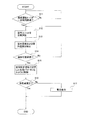
現地において、冷媒が予め充填された室外ユニット2と、室内ユニット4とを液冷媒連絡配管6およびガス冷媒連絡配管7を介して接続して冷媒回路10を構成した後に、リモコン(図示せず)を通じて、または、室内ユニット4の室内側制御部44や室外ユニット2の室外側制御部34に対して直接に、冷媒量判定運転モードの1つである冷媒自動充填運転を行うように指令を出すと、下記のステップS1からステップS7の手順で初回設定運転が行われる(図3参照)。なお、図3上では簡略化のために相対過冷却度を相対SCと表記する。
(Initial setting operation)
In the field, after the
−ステップS1、室内ユニットを冷房運転(室外ファン風量が最大)−
まず、ステップS1では、初回設定運転の開始指令がなされると、冷媒回路10は、室外ユニット2の四路切換弁22が図1の実線で示される状態(冷房運転状態)となる。そして、圧縮機21、室外ファン27が起動されて、室内ユニット4の全てについて強制的に冷房運転(通常運転モードにおける冷房運転とは室外ファン27の制御方法などが異なる)が行われる。なお、このとき室外ファン27は、その風量が最大になるように、モータ27mの回転数が最大となっている。ステップS1では、冷房運転状態において室外ファン27の風量を最大にしているため、室外熱交換器23により行われる熱交換効率の空気側における熱伝達率を最大にすることができ、外乱による影響を低減させることができる。なお、この効果についての検証は後述する。また、ここにいう「外乱」とは、室外熱交換器23の汚れ、室外ユニット2の設置状況、風雨の有無などである。そして、この室外ファン27の風量が最大になった時に、次のステップS2へ移行する。
-Step S1, cooling the indoor unit (maximum outdoor fan airflow)-
First, in step S1, when an instruction to start the initial setting operation is made, the
−ステップS2、温度の読込−
ステップS2では、室内温度センサ43により検出される室内温度Tbと、室外温度センサにより検出される室外温度Taとの読込が行われる。室内温度Tbと室外温度Taとが検出されると次のステップS3へ移行する。
-Step S2, temperature reading-
In step S2, the indoor temperature Tb detected by the
−ステップS3、検知可能範囲か否かの判定−
ステップS3では、検出された室内温度Tbと室外温度Taとが、予め設定されている冷媒量判定運転モードに適した所定の温度範囲(例えば、室内温度Tbが15℃から35℃の範囲、室外温度Taが0℃から50℃の範囲)内にあるか否かを判定する。ステップS3で、室内温度Tbと室外温度Taとが、所定の温度範囲内にあった場合には、その時の室内温度Tbを第1室内温度Tb1として記憶し、その時の室外温度Taを第1室外温度Ta1として記憶した上で、次のステップS4へ移行し、所定の温度範囲内になかった場合にはステップS1の冷房運転を継続することになる。
-Step S3, determination of whether or not the detection range-
In step S3, the detected indoor temperature Tb and outdoor temperature Ta are set to a predetermined temperature range suitable for the preset refrigerant amount determination operation mode (for example, the indoor temperature Tb is in the range of 15 ° C. to 35 ° C., outdoor It is determined whether or not the temperature Ta is within the range of 0 ° C. to 50 ° C. In step S3, when the indoor temperature Tb and the outdoor temperature Ta are within the predetermined temperature range, the indoor temperature Tb at that time is stored as the first indoor temperature Tb1, and the outdoor temperature Ta at that time is stored in the first outdoor temperature. After storing the temperature Ta1, the process proceeds to the next step S4, and if it is not within the predetermined temperature range, the cooling operation of step S1 is continued.
−ステップS4、相対SCが所定値以上であるか否かの判定−
ステップS4では、相対過冷却度値を導出し、相対過冷却度値が所定値以上(例えば、0.3以上)であるか否かを判定する。なお、ここにいう「相対過冷却度値」とは、室外熱交換器23の出口における過冷却度値を、凝縮温度値から室外温度を差し引いた値により除した値のことを言う。また、図面上では、相対過冷却度を相対SCと表記することにする。「相対過冷却度値」については、後に詳述する。本実施形態では、凝縮温度値は、凝縮圧力センサ29により検出される室外熱交換器23の出口側の圧力(凝縮圧力)値を冷媒の飽和温度に換算した値を用いている。ステップS4において、相対過冷却度値が所定値未満であると判定されると次のステップS5へ移行し、所定値未満であると判定されるとステップS6へ移行する。
-Step S4, Determination of whether the relative SC is equal to or greater than a predetermined value
In step S4, a relative supercooling degree value is derived, and it is determined whether or not the relative supercooling degree value is a predetermined value or more (for example, 0.3 or more). Here, the “relative supercooling value” refers to a value obtained by dividing the supercooling value at the outlet of the
−ステップS5、相対SCの制御−
ステップS5では、相対過冷却度値が所定値未満であるため、相対過冷却度値が所定値以上になるように、圧縮機21の回転周波数と室内熱交換器41の出口における過熱度とを制御する。例えば、圧縮機21の回転周波数が40Hz、室内熱交換器41の出口における過熱度を5℃の状態でステップS1における冷房運転を行い、相対過冷却度値が所定値以上であるか否かを判定する。この運転状態において、相対過冷却度値が所定値未満である場合には、圧縮機21の回転周波数をそのままにして、室内熱交換器41の出口における冷媒の過熱度を5℃上げて10℃にして相対過冷却度値を導出し、相対過冷却度値が所定値以上になるか否かを判定する。そして、相対過冷却度値が所定値未満である場合には、これを繰り返し、室内熱交換器41の出口における冷媒の過熱度が上がりきっても相対過冷却度値が所定値未満である場合には、圧縮機21の回転周波数を40Hzから例えば50Hzに上げて、室内熱交換器41の出口における冷媒の過熱度を5℃に下げて、同様に相対過冷却度値が所定値以上であるか否かを判定する。そして、上述したように室内熱交換器41の出口における冷媒の過熱度を再び5℃ずつ上げることを繰り返すことにより、相対過冷却度値が所定値以上になるように制御する。そして、相対過冷却度値が所定値以上になったら、ステップS6へ移行する。なお、室内熱交換器41の出口における冷媒の過熱度の制御(例えば過熱度を5℃から5℃ずつ上げていく制御)は、室外膨張弁33を開の状態から絞っていくことによって制御している。また、室内熱交換器41の出口における冷媒の過熱度の制御は、これに限らずに、室内ファン42の風量を制御することにより行っても構わないし、室外膨張弁33の弁開度の制御と室内ファン42の風量の制御とを併用して行っても構わない。なお、ここで室内熱交換器41の出口における冷媒の過熱度は、吸入温度センサ30により検出される冷媒温度値から、蒸発圧力センサ28により検出される蒸発圧力値を冷媒の飽和温度値に換算した値を、差し引くことによって検出される。
-Step S5, control of relative SC-
In step S5, since the relative supercooling degree value is less than the predetermined value, the rotational frequency of the
なお、ステップS5により過熱度が正値になるように制御されるため、図4で示されるように、アキュムレータ24に余剰冷媒が溜まっていない状態となり、アキュムレータ24に溜まっていた冷媒は室外熱交換器23に移動することになる。
Since the degree of superheat is controlled to be a positive value in step S5, as shown in FIG. 4, the
−ステップS6、相対SCを記憶−
ステップS6では、ステップS4またはステップS6において所定値以上である相対過冷却度値を初回相対過冷却度値として記憶し、次のステップS7へ移行する。
-Step S6, storing relative SC-
In step S6, the relative supercooling degree value that is equal to or greater than the predetermined value in step S4 or step S6 is stored as the initial relative supercooling degree value, and the process proceeds to the next step S7.
−ステップS7、パラメータを記憶−
ステップS7では、ステップS6において記憶した過冷却度値の際の運転状態における、圧縮機21の回転周波数と、室内ファン42の回転周波数と、室外温度Taと、室内温度Tbとを記憶して、初回設定運転を終了する。
-Step S7, parameter storage-
In step S7, the rotational frequency of the
(判定運転)
次に、冷媒量判定運転モードにおいて初回設定運転が行われた後に定期的に行われる運転である判定運転について、図5を用いて説明する。ここで、図5は、判定運転時のフローチャートである。なお、図5上では簡略化のために相対過冷却度を相対SCと表記する。
(Judgment operation)
Next, a determination operation that is an operation that is periodically performed after the initial setting operation is performed in the refrigerant amount determination operation mode will be described with reference to FIG. Here, FIG. 5 is a flowchart at the time of determination operation. In FIG. 5, the relative supercooling degree is expressed as relative SC for simplification.
この判定運転は、初回設定運転が行われた後に定期的(例えば、毎年1回、空調空間に負荷を必要としないとき等)に、通常運転モードにおける冷房運転や暖房運転から切り換えられて、不測の原因により冷媒回路内の冷媒が外部に漏洩していないか否かを検知する運転である。 This judgment operation is switched from the cooling operation or the heating operation in the normal operation mode periodically (for example, when a load is not required for the air-conditioned space once every year) after the initial setting operation is performed. This is an operation for detecting whether or not the refrigerant in the refrigerant circuit has leaked to the outside due to the cause.
−ステップS11、通常運転モードが一定時間経過したか否かの判定−
まず、上記の冷房運転や暖房運転のような通常運転モードにおける運転が一定時間経過したかどうかを判定し、通常運転モードにおける運転が一定時間経過した場合には、次のステップS12に移行する。
-Step S11, determination of whether or not the normal operation mode has passed a certain time-
First, it is determined whether or not the operation in the normal operation mode such as the cooling operation or the heating operation has elapsed for a certain period of time, and when the operation in the normal operation mode has elapsed for a certain period of time, the process proceeds to the next step S12.
−ステップS12、室内ユニットを冷房運転−
通常運転モードにおける運転が一定時間経過した場合には、上記の初回設定運転のステップS1と同様に、冷媒回路10が、室外ユニット2の四路切換弁22が図1の実線で示される状態となり、圧縮機21、室外ファン27が起動されて、室内ユニット4の全てについて強制的に冷房運転が行われる。
-Step S12, indoor unit cooling operation-
When the operation in the normal operation mode has passed for a certain period of time, the
−ステップS13、温度の読込−
ステップS13では、上記の初回設定運転のステップS2と同様に、室内温度と室外温度との読込が行われる。室内温度Tbと室外温度Taとが検出されると次のステップS14へ移行する。
-Step S13, temperature reading-
In step S13, the room temperature and the outdoor temperature are read in the same manner as in step S2 of the initial setting operation. When the indoor temperature Tb and the outdoor temperature Ta are detected, the process proceeds to the next step S14.
−ステップS14、検知可能範囲か否かの判定−
ステップS14では、上記の初回設定運転のステップS3と同様に、検出された室内温度Tbと室外温度Taとが第1室内温度Tb1と第1室外温度Ta1とに基づいて決定された範囲(例えば、初回設定運転により検出された室内温度Tbおよび室外温度Tbから±5℃の範囲、以下、第1温度範囲ar1とする)内であるか否かを判定する。ステップS14で、室内温度Tbと室外温度Taとが、第1温度範囲ar1内にあった場合には、その時の室内温度Tbを第2室内温度Tb2として記憶し、その時の室外温度Taを第2室外温度Ta2として記憶した上で、次のステップS15へ移行し、第1温度範囲ar1内になかった場合にはステップS12の冷房運転を継続することになる。なお、2回目以降の判定運転では、基準となる温度範囲は、初回設定運転により記憶された第1室内温度Tb1および第1室外温度Ta1と、2回目以降の判定運転の直前までに記憶された(すなわちステップS4およびステップS14により記憶された)室内温度および室外温度とに基づいて、すべての温度(室内温度と室外温度とのそれぞれにおいて)の±5℃の範囲に拡大されることになる。例えば、図6の点Aが第1室内温度Tb1および第1室外温度Ta1をプロットしたものであるとすると、最初の判定運転の際のステップS14において基準となる温度範囲(第1温度範囲ar1)は実線で囲まれた範囲となる。なお、図6は、ステップS3またはステップS14により検出された室内温度Tbと室外温度Taとの関係をプロットした点に基づいて求められた基準となる温度範囲を表すグラフである。そして、ステップS14において第1温度範囲ar1内に第2室内温度Tb2および第2室外温度Ta2検出されたとすると、2回目の判定運転の際のステップS14において基準となる温度範囲(第2温度範囲ar2)は、第2室内温度Tb2および第2室外温度Ta2(点B)に基づいた破線で囲まれた温度範囲を加えた範囲となる。なお、図6において、点Aを基準に特定される第1温度範囲ar1の枠と、点Bを基準に特定される第2温度範囲ar2の枠とは、合同である。このように、2回目以降の判定運転では、所定の温度範囲にあった場合の各温度条件が記憶され、それに伴い所定の温度範囲が拡大されていくことになる。
-Step S14, determination of whether or not it is in a detectable range-
In step S14, similarly to step S3 of the initial setting operation described above, a range in which the detected indoor temperature Tb and outdoor temperature Ta are determined based on the first indoor temperature Tb1 and the first outdoor temperature Ta1 (for example, It is determined whether the temperature is within a range of ± 5 ° C. from the indoor temperature Tb and the outdoor temperature Tb detected by the initial setting operation (hereinafter referred to as a first temperature range ar1). In step S14, when the indoor temperature Tb and the outdoor temperature Ta are within the first temperature range ar1, the indoor temperature Tb at that time is stored as the second indoor temperature Tb2, and the outdoor temperature Ta at that time is stored as the second outdoor temperature Ta. After storing as the outdoor temperature Ta2, the process proceeds to the next step S15, and if it is not within the first temperature range ar1, the cooling operation of step S12 is continued. In the second and subsequent determination operations, the reference temperature range is stored by the first indoor temperature Tb1 and the first outdoor temperature Ta1 stored by the initial setting operation and immediately before the second and subsequent determination operations. Based on the room temperature and the outdoor temperature (stored in steps S4 and S14), all the temperatures (in each of the room temperature and the outdoor temperature) are expanded to a range of ± 5 ° C. For example, assuming that the point A in FIG. 6 is a plot of the first indoor temperature Tb1 and the first outdoor temperature Ta1, the temperature range (first temperature range ar1) serving as a reference in step S14 during the first determination operation. Is the range surrounded by a solid line. FIG. 6 is a graph showing a reference temperature range obtained based on the plotted points of the relationship between the indoor temperature Tb and the outdoor temperature Ta detected in step S3 or step S14. If the second indoor temperature Tb2 and the second outdoor temperature Ta2 are detected in the first temperature range ar1 in step S14, the reference temperature range (second temperature range ar2 in step S14 in the second determination operation). ) Is a range obtained by adding a temperature range surrounded by a broken line based on the second indoor temperature Tb2 and the second outdoor temperature Ta2 (point B). In FIG. 6, the frame of the first temperature range ar1 specified based on the point A and the frame of the second temperature range ar2 specified based on the point B are congruent. Thus, in the second and subsequent determination operations, each temperature condition when the temperature is within the predetermined temperature range is stored, and the predetermined temperature range is expanded accordingly.
−ステップS15、初回設定運転における条件に制御−
ステップS15では、上記の初回設定運転のステップS7において記憶した圧縮機21の回転周波数と、室内ファン42の回転周波数とに、圧縮機21および室内ファン42を制御する。これにより、冷媒回路10内部の冷媒の状態を、初回設定運転と同様の状態であると見なすことができる。すなわち、冷媒回路10内の冷媒量が変化していなければ、初回設定運転において行った冷房運転の諸条件を同一のものとして再現していることになり、過冷却度値などをほぼ同じ値にできる。ステップS15が終了すると、次のステップS16へ移行する。
-Control to the conditions in step S15, initial setting operation-
In step S15, the
−ステップS16、冷媒量の適否の判定−
ステップS16では、上記の初回設定運転のステップS4と同様に、相対過冷却度を導出する。そして、初回相対過冷却度から相対過冷却度を差し引いた値(以下、相対過冷却度差とする)が第2所定値以上であるか否かを判定する。ステップS16において、相対過冷却度差が第2所定値未満であると判定されるとその相対過冷却度地を第2相対過冷却度値としてステップS14により記憶された第2室内温度Tb2および第2室外温度Ta2と関連付けされて記憶し、判定運転を終了し、相対過冷却度差が第2所定値以上であると判定されるとステップS17へ移行する。なお、2回目以降の判定運転においては、拡大された所定の温度範囲の基になった室内温度および室外温度と関連付けられた相対過冷却度値と比較されることになる。また、この場合に、基準となるべき相対過冷却度値が複数ある場合には、どちらか一方を基準にすればよい。
-Step S16, determination of appropriateness of refrigerant amount-
In step S16, the degree of relative supercooling is derived as in step S4 of the initial setting operation. Then, it is determined whether or not a value obtained by subtracting the relative supercooling degree from the initial relative supercooling degree (hereinafter referred to as a relative supercooling degree difference) is equal to or greater than a second predetermined value. If it is determined in step S16 that the relative subcooling degree difference is less than the second predetermined value, the second indoor temperature Tb2 and the second room temperature Tb2 stored in step S14 with the relative supercooling degree area as the second relative supercooling degree value are stored. 2 The outdoor temperature Ta2 is stored in association with each other, the determination operation is terminated, and if it is determined that the relative subcooling degree difference is equal to or greater than the second predetermined value, the process proceeds to step S17. In the second and subsequent determination operations, the relative supercooling degree value associated with the indoor temperature and the outdoor temperature that are the basis of the expanded predetermined temperature range is compared. In this case, if there are a plurality of relative supercooling degree values to be used as a reference, one of them may be used as a reference.
−ステップS17、警告表示−
ステップS17では、冷媒の漏洩が発生しているものと判定して、冷媒漏洩を検知したことを知らせる警告表示を行った後に、判定運転を終了する。
-Step S17, warning display-
In step S <b> 17, it is determined that the refrigerant has leaked, and after performing a warning display notifying that the refrigerant leak has been detected, the determination operation is terminated.
<相対SC値について>
相対過冷却度値について図7〜9にもとづいて説明する。
<Relative SC value>
The relative subcooling value will be described with reference to FIGS.
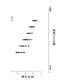
まず、図7は、室外ファン風量に対する室外温度Taが一定の際の凝縮温度Tcおよび室外熱交換器出口温度Tlを表すグラフである。図7を見ると、室外温度Taが一定の条件においては、室外ファン風量が増大するにしたがって、凝縮温度Tcおよび室外熱交換器出口温度Tlが減少していく。そして、その減少の落差は、凝縮温度Tcの方が室外熱交換器出口温度Tlよりも大きい。すなわち、室外ファン風量が大きくなると、凝縮温度Tcと室外熱交換器出口温度Tlとの差である過冷却度値が小さくなることが分かる。 First, FIG. 7 is a graph showing the condensation temperature Tc and the outdoor heat exchanger outlet temperature Tl when the outdoor temperature Ta is constant with respect to the outdoor fan air volume. Referring to FIG. 7, under the condition where the outdoor temperature Ta is constant, the condensation temperature Tc and the outdoor heat exchanger outlet temperature Tl decrease as the outdoor fan air volume increases. The drop of the decrease is that the condensation temperature Tc is larger than the outdoor heat exchanger outlet temperature Tl. That is, it is understood that when the outdoor fan air volume increases, the degree of supercooling, which is the difference between the condensation temperature Tc and the outdoor heat exchanger outlet temperature Tl, decreases.
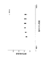
ここで、室外ファン風量に対する過冷却度値の分布を表すグラフである図8をみると、室外ファン風量が増大すると、過冷却度値が小さくなっていることが分かる。また、図8では、室外ファン風量が小さい場合の方が、室外ファン風量が大きい場合よりも過冷却度値のバラツキが大きくなっている。これは、室外ファン風量が小さい場合の方が、室外熱交換器の汚れ、室外機の設置状況、風雨などの外乱の影響を受けやすく、室外ファン風量が大きい場合の方が外乱の影響を受けにくいためであると考えられる。このため、室外ファン風量を最大にすることにより、検出される過冷却度値のバラツキを抑えることができ、検知誤差を低減させることができる。 Here, it can be seen from FIG. 8 that is a graph showing the distribution of the supercooling degree value with respect to the outdoor fan air volume, as the outdoor fan air volume increases, the supercooling degree value decreases. In FIG. 8, the variation in the degree of supercooling is greater when the outdoor fan air volume is smaller than when the outdoor fan air volume is large. This is because when the outdoor fan airflow is small, it is more susceptible to disturbances such as dirt from the outdoor heat exchanger, outdoor unit installation, and wind and rain, and when the outdoor fan airflow is large, it is more susceptible to disturbances. This is thought to be because it is difficult. For this reason, by maximizing the outdoor fan air volume, it is possible to suppress variations in the detected supercooling degree value and reduce detection errors.
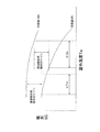
そして、図9は、室外ファン風量に対する相対過冷却度値の分布を表すグラフである。相対過冷却度値とは、上述したように、凝縮温度値から室外温度を差し引いた値により、過冷却度値を除した値である。図9を見ると、室外ファン風量の大小にかかわらず、その値はほぼ0.3から0.4の間に収まっており、バラツキが少ないことが分かる。このため、この相対過冷却度値を冷媒量の適否を判定する際に指標として利用することにより、外乱による影響を極力受けることなく冷媒量の適否を判定することができ、検知誤差を抑えることができる。したがって、相対過冷却度値を冷媒量の適否の判定に利用することは有用である。 FIG. 9 is a graph showing the distribution of the relative supercooling degree value with respect to the outdoor fan air volume. As described above, the relative supercooling degree value is a value obtained by dividing the supercooling degree value by the value obtained by subtracting the outdoor temperature from the condensation temperature value. Referring to FIG. 9, it can be seen that regardless of the magnitude of the outdoor fan air volume, the value is approximately between 0.3 and 0.4 and there is little variation. Therefore, by using this relative supercooling degree value as an index when determining the suitability of the refrigerant amount, it is possible to determine the suitability of the refrigerant amount without being affected by disturbance as much as possible, and to suppress detection errors. Can do. Therefore, it is useful to use the relative supercooling degree value for determining the suitability of the refrigerant amount.
(3)空気調和装置の特徴
本実施形態では、ステップS14において、上記の初回設定運転のステップS3と同様に、検出された室内温度Tbと室外温度Taとが第1室内温度Tb1と第1室外温度Ta1とに基づいて決定された範囲(例えば、初回設定運転により検出された室内温度Tbおよび室外温度Tbから±5℃の範囲)内であるか否かを判定している。そして、ステップS14で、室内温度Tbと室外温度Taとが、上述の温度範囲内にあった場合には、その時の室内温度Tbを第2室内温度Tb2として記憶し、その時の室外温度Taを第2室外温度Ta2として記憶した上で、次のステップS15へ移行し、所定の温度範囲内になかった場合にはステップS12の冷房運転を継続することになる。
(3) Features of the Air Conditioner In the present embodiment, in step S14, the detected indoor temperature Tb and outdoor temperature Ta are detected as the first indoor temperature Tb1 and the first outdoor temperature, as in step S3 of the initial setting operation. It is determined whether or not it is within a range determined based on the temperature Ta1 (for example, a range of ± 5 ° C. from the indoor temperature Tb and the outdoor temperature Tb detected by the initial setting operation). In step S14, when the indoor temperature Tb and the outdoor temperature Ta are within the above-described temperature range, the indoor temperature Tb at that time is stored as the second indoor temperature Tb2, and the outdoor temperature Ta at that time is stored as the first outdoor temperature Ta. After storing as the two outdoor temperatures Ta2, the process proceeds to the next step S15, and if it is not within the predetermined temperature range, the cooling operation of step S12 is continued.
なお、2回目以降の判定運転では、基準となる温度範囲は、初回設定運転により記憶された第1室内温度Tb1および第1室外温度Ta1と、2回目以降の判定運転の直前までに記憶された(すなわちステップS4およびステップS14により記憶された)室内温度および室外温度とに基づいて、すべての温度(室内温度と室外温度とのそれぞれにおいて)の±5℃の範囲に拡大されることになる。このように、2回目以降の判定運転では、所定の温度範囲にあった場合の各温度条件が記憶され、それに伴い所定の温度範囲が拡大されていくことになる。 In the second and subsequent determination operations, the reference temperature range is stored by the first indoor temperature Tb1 and the first outdoor temperature Ta1 stored by the initial setting operation and immediately before the second and subsequent determination operations. Based on the room temperature and the outdoor temperature (stored in steps S4 and S14), all the temperatures (in each of the room temperature and the outdoor temperature) are expanded to a range of ± 5 ° C. Thus, in the second and subsequent determination operations, each temperature condition when the temperature is within the predetermined temperature range is stored, and the predetermined temperature range is expanded accordingly.
したがって、できるだけ検知誤差が発生しないような環境条件の範囲内において、冷媒量の適否の判定を行うことができ、検知誤差を少なくできる。また、検知誤差が発生する環境条件の範囲内であることを認識すると、冷媒量適否判定を行わない、冷媒量適否判定を行うべき適切な条件ではないことを利用者に報告する、冷媒量適否判定を行うべき適切な条件を報告する、のうちの少なくとも1つを冷媒量適否不可制御として行うため、冷媒量適否判定ができなくとも利用者は冷媒量適否判定ができるように対策を講じることができるため、検知誤差が少ない条件において冷媒量適否判定をできるようにさせることができる。 Therefore, the suitability of the refrigerant amount can be determined within a range of environmental conditions in which detection errors do not occur as much as possible, and detection errors can be reduced. Also, if it is recognized that the detection error is within the range of environmental conditions, the refrigerant amount propriety determination is not performed, and the refrigerant amount propriety is reported to the user that the refrigerant amount propriety determination is not appropriate. Since at least one of reporting appropriate conditions to be judged is controlled as refrigerant quantity propriety control, measures should be taken so that the user can judge the refrigerant quantity suitability even if the refrigerant quantity suitability cannot be judged. Therefore, it is possible to determine whether or not the refrigerant amount is appropriate under the condition that the detection error is small.
(4)変形例1
本実施形態の判定運転時におけるステップS14において、第1温度範囲ar1として初回設定運転により検出された室内温度Tbおよび室外温度Taから±5℃の範囲幅と、室内温度Tbと室外温度Taとの両方からその温度範囲の範囲幅ΔTが一律に決定されているが、これに限らずに、少なくとも室外温度Taから第1温度範囲ar1の範囲幅ΔTを決定しても良く、また、その温度範囲が外気温度である室外温度Taと正の相関関係となるように、室外温度Taが大きい場合にはそのときの範囲幅ΔTが拡大するように変化しても良い。
(4)
In step S14 during the determination operation of the present embodiment, a range of ± 5 ° C. from the indoor temperature Tb and the outdoor temperature Ta detected by the initial setting operation as the first temperature range ar1, and the indoor temperature Tb and the outdoor temperature Ta Although the range width ΔT of the temperature range is uniformly determined from both, the present invention is not limited to this, and the range width ΔT of the first temperature range ar1 may be determined from at least the outdoor temperature Ta, and the temperature range When the outdoor temperature Ta is large, the range width ΔT at that time may be changed so as to be positively correlated with the outdoor temperature Ta which is the outdoor temperature.
例えば、室外温度Taが11℃の場合の第1温度範囲ar1の範囲幅を±4℃の第1範囲幅ΔT1とし、室外温度Taが26℃の場合の第1温度範囲ar1の範囲幅を±10℃の第2範囲幅ΔT2とするように、範囲幅ΔTを室外温度Taの変化に対して正の相関関係を持つように第1温度範囲ar1を決定しても良い(図10参照)。 For example, the range width of the first temperature range ar1 when the outdoor temperature Ta is 11 ° C. is the first range width ΔT1 of ± 4 ° C., and the range width of the first temperature range ar1 when the outdoor temperature Ta is 26 ° C. is ± The first temperature range ar1 may be determined so that the range width ΔT has a positive correlation with the change in the outdoor temperature Ta so that the second range width ΔT2 is 10 ° C. (see FIG. 10).
ここで、図11は、冷媒回路10に充填される冷媒量が100%から90%へと変化したときの相対過冷却度値の変化量(以下、相対SC変化量とする)と室外温度Taとの関係を示したグラフである。また、図12は、相対過冷却度値と室外温度Taとの関係を表すグラフであり、冷媒回路10に充填された冷媒量が100%ある場合と冷媒回路10に充填された冷媒量が90%ある場合とを示したものである。図11によると、室外温度Taが増加するに従って相対SC変化量も増加する傾向にある。さらに、図12に示すように、冷媒回路10内の冷媒量が100%から90%に10%減少したことを検知するための冷媒漏洩検知用の相対過冷却度値のマージン(ステップS16における第2所定値に相当)を確保すると、室外温度Taが低い場合である第1検知可能範囲ΔT1aに比べて室外温度Taの高い場合である第2検知可能範囲ΔT2aが大きいことから、室外温度Taが大きくなると冷媒量の変化を検知可能な室外温度Taの範囲が広がることが分かる。したがって、このような室外温度Taと第1温度範囲ar1を決定するための範囲幅ΔTとを関連づけたデータをあらかじめ記憶しておき、そのデータに基づいて第1温度範囲ar1を決定するようにすると、上記実施例よりも精度よく冷媒量の適否の判定を行うことが可能となる。このことから、冷媒量の適否の精度という観点から変形例(1)を適用する方が望ましいと言える。なお、このことは、第1温度範囲ar1だけでなく第2温度範囲ar2についても同様に言える。
Here, FIG. 11 shows the amount of change in the degree of relative supercooling (hereinafter referred to as the amount of change in relative SC) and the outdoor temperature Ta when the amount of refrigerant charged in the
(5)変形例2
本実施形態の判定運転時におけるステップS14において、室内温度Tbと室外温度Taとが第1温度範囲内になかった場合に、ステップS12の冷房運転を継続することにしているがこれに限らず、その時の室内温度Tbと室外温度Taとが第1温度範囲内にないことを利用者に報知するようにしても良いし、第1温度範囲内がどのような値の範囲であるかを利用者に報知しても良い。
(5)
In step S14 during the determination operation of the present embodiment, when the indoor temperature Tb and the outdoor temperature Ta are not within the first temperature range, the cooling operation in step S12 is continued, but not limited thereto. The user may be informed that the indoor temperature Tb and the outdoor temperature Ta at that time are not within the first temperature range, and the user can determine what value range is within the first temperature range. May be notified.
(6)変形例3
本実施形態において、室外熱交換器23の出口における冷媒の過冷却度は、凝縮圧力センサ29により検出される室外熱交換器23の出口側の冷媒圧力(凝縮圧力に相当)値を冷媒の飽和温度値に換算し、液側温度センサ31により検出される冷媒温度値をこの冷媒の飽和温度値から差し引くことによって検出しているが、これに限らない。
(6) Modification 3
In the present embodiment, the degree of refrigerant supercooling at the outlet of the
例えば、室外熱交換器23の冷媒の温度を検出可能な室外熱交センサを設けて凝縮温度値を冷媒の飽和温度値として検出し、液側温度センサ31により検出される冷媒温度値をこの冷媒の飽和温度値から差し引くことによって検出しても構わない。
For example, an outdoor heat exchange sensor capable of detecting the temperature of the refrigerant in the
(7)変形例4
本実施形態において、相対過冷却度値を冷媒量の適否の判定の指標としているが、これに限らず、室外ファン風量を最大にした状態で検出した過冷却度値を冷媒量の適否の判定の指標としても構わない。
(7)
In the present embodiment, the relative supercooling value is used as an index for determining the suitability of the refrigerant amount. It does not matter as an indicator.
(8)変形例5
本実施形態においては、図5およびその説明に示されたように、通常運転モードと冷媒量判定運転モードとが一定の時間間隔で切り換える制御を行う場合を例として挙げているが、これに限定されるものではない。
(8) Modification 5
In the present embodiment, as shown in FIG. 5 and the description thereof, a case where control is performed to switch between the normal operation mode and the refrigerant amount determination operation mode at a constant time interval is given as an example. Is not to be done.
例えば、制御的に切り換えられるのではなく、空気調和装置1に冷媒量判定運転モードに切り換えるためのスイッチ等を設けておき、サービスマンや設備管理者が、現地において、スイッチ等を操作することにより、冷媒漏洩検知運転を定期的に行うようなものであってもよい。
For example, instead of being controlled, the
(9)他の実施形態
以上、本発明の実施形態について図面に基づいて説明したが、具体的な構成は、これらの実施形態に限られるものではなく、発明の要旨を逸脱しない範囲で変更可能である。
(9) Other Embodiments Although the embodiments of the present invention have been described with reference to the drawings, the specific configuration is not limited to these embodiments and can be changed without departing from the gist of the invention. It is.
例えば、上述の実施形態では、冷暖切り換え可能な空気調和装置に本発明を適用した例を説明したが、これに限定されず、セパレートタイプの空気調和装置であれば適用可能であり、ペア型の空気調和装置、冷房専用の空気調和装置や冷暖同時運転可能な空気調和装置に本発明を適用してもよい。 For example, in the above-described embodiment, an example in which the present invention is applied to an air conditioner capable of switching between heating and cooling has been described. However, the present invention is not limited thereto, and can be applied to a separate type air conditioner, and is a pair type The present invention may be applied to an air conditioner, an air conditioner dedicated to cooling, or an air conditioner capable of simultaneous cooling and heating.
本発明を利用すれば、熱源ユニットと利用ユニットとが冷媒連絡配管を介して接続されたセパレートタイプの空気調和装置において、冷媒回路内に充填されている冷媒量の適否を精度良く判定できるようにすることができる。 By using the present invention, in a separate type air conditioner in which a heat source unit and a utilization unit are connected via a refrigerant communication pipe, it is possible to accurately determine the suitability of the amount of refrigerant charged in the refrigerant circuit. can do.
1 空気調和装置
2 室外ユニット(熱源ユニット)
4 室内ユニット(利用ユニット)
6 液冷媒連絡配管
7 ガス冷媒連絡配管
10 冷媒回路
21 圧縮機
23 室外熱交換器(熱源側熱交換器)
27 室外ファン(冷却熱源調節手段)
33 室外膨張弁(膨張機構)
41 利用側熱交換器
ar1 第1温度範囲
ar2 第2温度範囲
1
4 Indoor units (units used)
6 Liquid refrigerant communication pipe 7 Gas
27 Outdoor fan (cooling heat source adjustment means)
33 Outdoor expansion valve (expansion mechanism)
41 user side heat exchanger ar1 first temperature range ar2 second temperature range
Claims (6)
前記利用ユニットの運転負荷に応じて前記熱源ユニットおよび前記利用ユニットの各機器の制御を行う通常運転モードから、前期冷房運転し前記利用側熱交換器の出口における冷媒の過熱度が正値になるように前記膨張機構を制御しつつ前記熱源側熱交換器の出口における冷媒の過冷却度または前記過冷却度の変動に応じて変動する運転状態量を検出して、前記過冷却度が第1所定値以上に、または、前記運転状態量が第2所定値以上にした安定状態にする初期運転ステップと、
前記安定状態における前記圧縮機の周波数を第1周波数として、前記安定状態における前記利用側熱交換器の出口の冷媒の過熱度を第1過熱度として、前記安定状態における前記過冷却度または前記運転状態量を指標値として、前記初期運転ステップにおける環境条件を第1条件として記憶する記憶ステップと、
前記記憶ステップから所定期間経過後の環境条件が前記第1条件に基づいて換算される範囲である第1条件範囲(ar1)内にある場合に、前記記憶ステップにより記憶された前記第1周波数になるように前記圧縮機の制御を行い、かつ、前記第1過熱度になるように前記膨張機構の制御を行いつつ前記熱源側熱交換器の出口における冷媒の過冷却度または前記過冷却度の変動に応じて変動する運転状態量を検出値として検出して、前記指標値と前記検出値とを比較して、前記冷媒回路内に充填されている冷媒量の適否を判定する冷媒量適否判定を行い、前記記憶ステップから所定期間経過後の環境条件が前記第1条件範囲内にない場合に、前記冷媒量適否判定を行わない、前記冷媒量適否判定を行うべき適切な条件ではないことを報告する、前記冷媒量適否判定を行うべき適切な条件を報告する、のうちの少なくとも1つを冷媒量適否不可制御として行う条件判定ステップと、
を備えた空気調和装置の冷媒量判定方法。 A heat source unit (2) having a compressor (21) and a heat source side heat exchanger (23) capable of adjusting the operating capacity, a utilization unit (4) having a utilization side heat exchanger (41), an expansion mechanism ( 33), a liquid refrigerant communication pipe (6) and a gas refrigerant communication pipe (7) for connecting the heat source unit and the utilization unit, and the heat source side heat exchanger of the refrigerant compressed in the compressor In an air conditioner having a refrigerant circuit (10) capable of performing at least a cooling operation as a condenser and causing the use side heat exchanger to function as an evaporator of refrigerant condensed in the heat source side heat exchanger. A refrigerant amount determination method for determining the suitability of the refrigerant amount in the refrigerant circuit,
From the normal operation mode in which the heat source unit and each device of the utilization unit are controlled in accordance with the operation load of the utilization unit, the refrigerant superheat degree at the outlet of the utilization side heat exchanger is positive after the previous cooling operation. In this way, while controlling the expansion mechanism, the degree of subcooling of the refrigerant at the outlet of the heat source side heat exchanger or the operating state quantity that varies according to the fluctuation of the degree of subcooling is detected, and the degree of subcooling is the first. An initial operation step of making a stable state equal to or greater than a predetermined value or the operation state quantity being equal to or greater than a second predetermined value;
The frequency of the compressor in the stable state is a first frequency, the degree of superheat of the refrigerant at the outlet of the use side heat exchanger in the stable state is a first superheat degree, and the degree of supercooling or the operation in the stable state A storage step of storing the environmental condition in the initial operation step as a first condition using the state quantity as an index value;
When the environmental condition after the elapse of a predetermined period from the storing step is within the first condition range (ar1) that is a range converted based on the first condition, the first frequency stored in the storing step is set to the first frequency. The compressor is controlled so that the first superheat degree is controlled, and the expansion mechanism is controlled so that the first superheat degree is reached, and the degree of supercooling of the refrigerant at the outlet of the heat source side heat exchanger or the degree of supercooling is controlled. A refrigerant amount propriety determination is performed by detecting, as a detected value, an operating state variable that varies according to the fluctuation, comparing the index value and the detected value, and determining whether the refrigerant amount charged in the refrigerant circuit is appropriate. When the environmental condition after a predetermined period has elapsed from the storage step is not within the first condition range, the refrigerant amount suitability determination is not performed, and the refrigerant amount suitability determination is not an appropriate condition. Report Report the appropriate conditions to perform the refrigerant quantity adequacy determination, the conditional step of performing a refrigerant quantity adequacy Call control at least one of,
A method for determining the amount of refrigerant in an air conditioner comprising:
請求項1に記載の空気調和装置の冷媒量判定方法。 The environmental condition includes at least one of an outside air temperature, an outside air temperature based on a calendar, and a weather condition acquired from the outside.
The refrigerant | coolant amount determination method of the air conditioning apparatus of Claim 1.
前記第1条件範囲は、前記外気温度に基づいて、その範囲の幅である第1範囲幅が決定され、
前記第1範囲幅は、前記外気温度と正の相関関係にある、
請求項1または2に記載の空気調和装置の冷媒量判定方法。 The first condition includes at least an outside air temperature,
The first condition range is determined based on the outside air temperature, a first range width that is a width of the range,
The first range width is positively correlated with the outside air temperature.
The refrigerant | coolant amount determination method of the air conditioning apparatus of Claim 1 or 2.
前記条件判定ステップにおいて、前記記憶ステップから所定期間経過後の環境条件が前記第1条件範囲内にある場合に、その時の環境条件を第2条件として記憶し、前記第2条件に基づいて換算される範囲である第2条件範囲(ar2)を導出し、次回行われる前記条件判定ステップにおいて、前記第1条件範囲と前記第2条件範囲とを加えた拡大条件範囲内にその時の環境条件がある場合には前記冷媒量適否判定を行い、前記第1条件範囲と前記第2条件範囲とを加えた拡大条件範囲内にその時の環境条件がない場合には前記冷媒量適否不可制御を行う、
請求項1から3のいずれかに記載の空気調和装置の冷媒量判定方法。 The condition determining step is periodically performed after the predetermined period from the storing step,
In the condition determining step, when an environmental condition after a predetermined period has elapsed from the storing step is within the first condition range, the environmental condition at that time is stored as a second condition, and converted based on the second condition. A second condition range (ar2) that is a range to be determined, and in the condition determination step performed next time, the environmental condition at that time is within the expanded condition range obtained by adding the first condition range and the second condition range In this case, the refrigerant quantity suitability determination is performed, and when there is no environmental condition at that time within the expanded condition range obtained by adding the first condition range and the second condition range, the refrigerant quantity suitability control is performed.
The refrigerant | coolant amount determination method of the air conditioning apparatus in any one of Claim 1 to 3.
前記第2条件範囲は、前記外気温度に基づいて、その範囲の幅である第2範囲幅が決定され、
前記第2範囲幅は、前記外気温度と正の相関関係にある、
請求項3に記載の空気調和装置の冷媒量判定方法。 The second condition includes at least an outside air temperature,
The second condition range is determined based on the outside air temperature, a second range width that is the width of the range,
The second range width is positively correlated with the outside air temperature.
The refrigerant | coolant amount determination method of the air conditioning apparatus of Claim 3.
前記利用ユニットの運転負荷に応じて前記熱源ユニットおよび前記利用ユニットの各機器の制御を行う通常運転モードから、前期冷房運転し前記利用側熱交換器の出口における冷媒の過熱度が正値になるように前記膨張機構を制御しつつ前記熱源側熱交換器の出口における冷媒の過冷却度または前記過冷却度の変動に応じて変動する運転状態量を検出して、前記過冷却度が第1所定値以上に、または、前記運転状態量が第2所定値以上にした安定状態にする初期運転手段と、
前記安定状態における前記圧縮機の周波数を第1周波数として、前記安定状態における前記利用側熱交換器の出口の冷媒の過熱度を第1過熱度として、前記安定状態における前記過冷却度または前記運転状態量を指標値として、前記初期運転ステップにおける環境条件を第1条件として記憶する記憶手段と、
前記記憶ステップから所定期間経過後の環境条件が前記第1条件に基づいて換算される範囲である第1条件範囲内にある場合に、前記記憶ステップにより記憶された前記第1周波数になるように前記圧縮機の制御を行い、かつ、前記第1過熱度になるように前記膨張機構の制御を行いつつ前記熱源側熱交換器の出口における冷媒の過冷却度または前記過冷却度の変動に応じて変動する運転状態量を検出値として検出して、前記指標値と前記検出値とを比較して、前記冷媒回路内に充填されている冷媒量の適否を判定する冷媒量適否判定を行い、前記記憶ステップから所定期間経過後の環境条件が前記第1条件範囲内にない場合に、前記冷媒量適否判定を行わない、前記冷媒量適否判定を行うべき適切な条件ではないことを報告する、前記冷媒量適否判定を行うべき適切な条件を報告する、のうちの少なくとも1つ冷媒量適否不可制御として行う条件判定手段と、
を備える空気調和装置(1)。
A heat source unit (2) having a compressor (21) and a heat source side heat exchanger (23) with adjustable operating capacity, a utilization unit (4) having a utilization side heat exchanger, and an expansion mechanism (33) And a liquid refrigerant communication pipe (6) and a gas refrigerant communication pipe (7) connecting the heat source unit and the utilization unit, and the heat source side heat exchanger is used as a refrigerant condenser to be compressed in the compressor. And a refrigerant circuit (10) capable of performing at least a cooling operation for causing the use side heat exchanger to function as an evaporator of refrigerant condensed in the heat source side heat exchanger;
From the normal operation mode in which the heat source unit and each device of the utilization unit are controlled in accordance with the operation load of the utilization unit, the refrigerant superheat degree at the outlet of the utilization side heat exchanger is positive after the previous cooling operation. In this way, while controlling the expansion mechanism, the degree of subcooling of the refrigerant at the outlet of the heat source side heat exchanger or the operating state quantity that varies according to the fluctuation of the degree of subcooling is detected, and the degree of subcooling is the first. An initial operation means for achieving a stable state in which the operation state quantity is equal to or greater than a predetermined value or greater than a second predetermined value;
The frequency of the compressor in the stable state is a first frequency, the degree of superheat of the refrigerant at the outlet of the use side heat exchanger in the stable state is a first superheat degree, and the degree of supercooling or the operation in the stable state Storage means for storing the environmental condition in the initial operation step as a first condition using the state quantity as an index value;
When the environmental condition after the lapse of a predetermined period from the storing step is within a first condition range that is a range converted based on the first condition, the first frequency stored in the storing step is set to be the first frequency. Depending on the degree of subcooling of the refrigerant at the outlet of the heat source side heat exchanger or the variation of the degree of supercooling while controlling the compressor and controlling the expansion mechanism so as to achieve the first degree of superheating. Detecting an operating state amount that fluctuates as a detection value, comparing the index value and the detection value, and performing a refrigerant amount propriety determination to determine the propriety of the refrigerant amount charged in the refrigerant circuit, When the environmental condition after the lapse of a predetermined period from the storage step is not within the first condition range, it is reported that the refrigerant amount suitability determination is not performed and the refrigerant amount suitability determination is not an appropriate condition. The refrigerant A condition judging means for performing a propriety Report appropriate conditions to make a determination, at least one refrigerant quantity adequacy Call control of,
An air conditioner (1) comprising:
Priority Applications (1)
| Application Number | Priority Date | Filing Date | Title |
|---|---|---|---|
| JP2008169598A JP5245576B2 (en) | 2008-06-27 | 2008-06-27 | Refrigerant amount determination method for air conditioner and air conditioner |
Applications Claiming Priority (1)
| Application Number | Priority Date | Filing Date | Title |
|---|---|---|---|
| JP2008169598A JP5245576B2 (en) | 2008-06-27 | 2008-06-27 | Refrigerant amount determination method for air conditioner and air conditioner |
Publications (2)
| Publication Number | Publication Date |
|---|---|
| JP2010007997A true JP2010007997A (en) | 2010-01-14 |
| JP5245576B2 JP5245576B2 (en) | 2013-07-24 |
Family
ID=41588709
Family Applications (1)
| Application Number | Title | Priority Date | Filing Date |
|---|---|---|---|
| JP2008169598A Active JP5245576B2 (en) | 2008-06-27 | 2008-06-27 | Refrigerant amount determination method for air conditioner and air conditioner |
Country Status (1)
| Country | Link |
|---|---|
| JP (1) | JP5245576B2 (en) |
Cited By (3)
| Publication number | Priority date | Publication date | Assignee | Title |
|---|---|---|---|---|
| JP2013250038A (en) * | 2012-06-04 | 2013-12-12 | Daikin Industries Ltd | Refrigeration device management system |
| JP2016099059A (en) * | 2014-11-21 | 2016-05-30 | 三菱電機株式会社 | Refrigeration cycle device |
| WO2016135904A1 (en) * | 2015-02-25 | 2016-09-01 | 三菱電機株式会社 | Refrigeration apparatus |
Citations (4)
| Publication number | Priority date | Publication date | Assignee | Title |
|---|---|---|---|---|
| JP2006058007A (en) * | 2004-06-11 | 2006-03-02 | Daikin Ind Ltd | Air conditioner |
| JP2006292213A (en) * | 2005-04-07 | 2006-10-26 | Daikin Ind Ltd | Air conditioner |
| JP2008064456A (en) * | 2007-11-28 | 2008-03-21 | Daikin Ind Ltd | Air conditioner |
| WO2008035418A1 (en) * | 2006-09-21 | 2008-03-27 | Mitsubishi Electric Corporation | Refrigerating/air conditioning system having refrigerant learage detecting function, refrigerator/air conditioner and method for detecting leakage of refrigerant |
-
2008
- 2008-06-27 JP JP2008169598A patent/JP5245576B2/en active Active
Patent Citations (4)
| Publication number | Priority date | Publication date | Assignee | Title |
|---|---|---|---|---|
| JP2006058007A (en) * | 2004-06-11 | 2006-03-02 | Daikin Ind Ltd | Air conditioner |
| JP2006292213A (en) * | 2005-04-07 | 2006-10-26 | Daikin Ind Ltd | Air conditioner |
| WO2008035418A1 (en) * | 2006-09-21 | 2008-03-27 | Mitsubishi Electric Corporation | Refrigerating/air conditioning system having refrigerant learage detecting function, refrigerator/air conditioner and method for detecting leakage of refrigerant |
| JP2008064456A (en) * | 2007-11-28 | 2008-03-21 | Daikin Ind Ltd | Air conditioner |
Cited By (7)
| Publication number | Priority date | Publication date | Assignee | Title |
|---|---|---|---|---|
| JP2013250038A (en) * | 2012-06-04 | 2013-12-12 | Daikin Industries Ltd | Refrigeration device management system |
| WO2013183414A1 (en) * | 2012-06-04 | 2013-12-12 | ダイキン工業株式会社 | Refrigeration device management system |
| US9791195B2 (en) | 2012-06-04 | 2017-10-17 | Daikin Industries, Ltd. | Cooling device management system with refrigerant leakage detection function |
| JP2016099059A (en) * | 2014-11-21 | 2016-05-30 | 三菱電機株式会社 | Refrigeration cycle device |
| US10145595B2 (en) | 2014-11-21 | 2018-12-04 | Mitsubishi Electric Corporation | Refrigeration cycle apparatus |
| WO2016135904A1 (en) * | 2015-02-25 | 2016-09-01 | 三菱電機株式会社 | Refrigeration apparatus |
| JPWO2016135904A1 (en) * | 2015-02-25 | 2017-09-07 | 三菱電機株式会社 | Refrigeration equipment |
Also Published As
| Publication number | Publication date |
|---|---|
| JP5245576B2 (en) | 2013-07-24 |
Similar Documents
| Publication | Publication Date | Title |
|---|---|---|
| WO2009157200A1 (en) | Method for judging amount of refrigerant of air conditioner and air conditioner | |
| KR101161240B1 (en) | Air conditioner | |
| WO2009157191A1 (en) | Air conditioner and method for determining the amount of refrigerant therein | |
| JP4705878B2 (en) | Air conditioner | |
| JP4215022B2 (en) | Air conditioner | |
| JP4462096B2 (en) | Air conditioner | |
| JP2009079842A (en) | Refrigerating cycle device and its control method | |
| JP2007163100A (en) | Air conditioner | |
| CN112840164B (en) | Air conditioner and management device | |
| JP4839861B2 (en) | Air conditioner | |
| JP2008175444A (en) | Air conditioner | |
| JP5505477B2 (en) | AIR CONDITIONER AND REFRIGERANT AMOUNT JUDGING METHOD FOR AIR CONDITIONER | |
| JP2011099591A (en) | Refrigerating device | |
| JP4957243B2 (en) | Air conditioner | |
| JP2011012958A (en) | Method for controlling refrigeration cycle apparatus | |
| JP2010096396A (en) | Refrigerant amount determining method of air conditioning device, and air conditioning device | |
| JP2010007996A (en) | Trial operation method of air conditioner and air conditioner | |
| JP2006292214A (en) | Addition method of refrigerant amount determining function of air conditioner, and air conditioner | |
| JP2017075760A (en) | Air conditioner | |
| JP2008064456A (en) | Air conditioner | |
| JP5245576B2 (en) | Refrigerant amount determination method for air conditioner and air conditioner | |
| JP5245575B2 (en) | Refrigerant amount determination method for air conditioner and air conditioner | |
| AU2013200092B2 (en) | Air conditioning apparatus and air conditioning apparatus refrigerant quantity determination method | |
| JP2007163101A (en) | Air conditioner | |
| JP2008111584A (en) | Air conditioner |
Legal Events
| Date | Code | Title | Description |
|---|---|---|---|
| A621 | Written request for application examination |
Free format text: JAPANESE INTERMEDIATE CODE: A621 Effective date: 20110520 |
|
| A977 | Report on retrieval |
Free format text: JAPANESE INTERMEDIATE CODE: A971007 Effective date: 20120822 |
|
| A131 | Notification of reasons for refusal |
Free format text: JAPANESE INTERMEDIATE CODE: A131 Effective date: 20120925 |
|
| A521 | Written amendment |
Free format text: JAPANESE INTERMEDIATE CODE: A523 Effective date: 20121114 |
|
| TRDD | Decision of grant or rejection written | ||
| A01 | Written decision to grant a patent or to grant a registration (utility model) |
Free format text: JAPANESE INTERMEDIATE CODE: A01 Effective date: 20130312 |
|
| A61 | First payment of annual fees (during grant procedure) |
Free format text: JAPANESE INTERMEDIATE CODE: A61 Effective date: 20130325 |
|
| R151 | Written notification of patent or utility model registration |
Ref document number: 5245576 Country of ref document: JP Free format text: JAPANESE INTERMEDIATE CODE: R151 |
|
| FPAY | Renewal fee payment (event date is renewal date of database) |
Free format text: PAYMENT UNTIL: 20160419 Year of fee payment: 3 |