JP2010007847A - Oil supply structure for engine - Google Patents

Oil supply structure for engine Download PDF

Info

Publication number
JP2010007847A
JP2010007847A JP2008171630A JP2008171630A JP2010007847A JP 2010007847 A JP2010007847 A JP 2010007847A JP 2008171630 A JP2008171630 A JP 2008171630A JP 2008171630 A JP2008171630 A JP 2008171630A JP 2010007847 A JP2010007847 A JP 2010007847A
Authority
JP
Japan
Prior art keywords
oil
engine
shaft
drive
bevel
Prior art date
Legal status (The legal status is an assumption and is not a legal conclusion. Google has not performed a legal analysis and makes no representation as to the accuracy of the status listed.)
Granted
Application number
JP2008171630A
Other languages
Japanese (ja)
Other versions
JP5286976B2 (en
Inventor
Nobuhiro Yasui
信博 安井
Current Assignee (The listed assignees may be inaccurate. Google has not performed a legal analysis and makes no representation or warranty as to the accuracy of the list.)
Suzuki Motor Corp
Original Assignee
Suzuki Motor Corp
Priority date (The priority date is an assumption and is not a legal conclusion. Google has not performed a legal analysis and makes no representation as to the accuracy of the date listed.)
Filing date
Publication date
Application filed by Suzuki Motor Corp filed Critical Suzuki Motor Corp
Priority to JP2008171630A priority Critical patent/JP5286976B2/en
Publication of JP2010007847A publication Critical patent/JP2010007847A/en
Application granted granted Critical
Publication of JP5286976B2 publication Critical patent/JP5286976B2/en
Active legal-status Critical Current
Anticipated expiration legal-status Critical

Links

Images

Abstract

<P>PROBLEM TO BE SOLVED: To surely prevent a lack of oil supply to a counter shaft or a drive shaft when restarting an engine. <P>SOLUTION: In an engine of a shaft drive type motorcycle, a crank shaft 31, a counter shaft 32 and a drive shaft 33 are arranged to be rotatably supported in order in parallel with each other inside an engine case 20. A bevel drive gear 62 is integrally provided with the drive shaft for rotation, and a bevel driven gear 63 to be engaged with the bevel drive gear is integrally provided with a drive shaft for rotation, and engine power is transmitted to a rear wheel through the driven shaft 61 and a propeller shaft 22. The engine of the shaft drive type motorcycle has an oil passage 77 for supplying oil from an oil pump to the drive shaft 33, and the oil passage comprises a first oil reservoir part 85 near a shaft end of the counter shaft on a side wherein the bevel drive gear and the bevel driven gear are arranged, and oil is led to the drive shaft 33 through the first oil reservoir part. <P>COPYRIGHT: (C)2010,JPO&INPIT

Description

本発明は、エンジンの動力をベベルギヤユニット及びプロペラシャフトを介して駆動輪へ伝達するシャフトドライブ式の自動二輪車におけるエンジンのオイル供給構造に関する。   The present invention relates to an engine oil supply structure in a shaft drive type motorcycle that transmits engine power to drive wheels via a bevel gear unit and a propeller shaft.

シャフトドライブ式の自動二輪車のエンジンにあっては、クランクシャフトの回転力を、ベベルドライブギヤ及びベベルドリブンギヤ(ベベルギヤユニット)を介してプロペラシャフトへ伝達し、駆動輪を駆動している。   In a shaft drive type motorcycle engine, the rotational force of a crankshaft is transmitted to a propeller shaft via a bevel drive gear and a bevel driven gear (bevel gear unit) to drive the drive wheels.

特許文献1に記載のエンジンでは、オイルポンプ(P)からの潤滑油(オイル)を、送油路(36)、注油管(37)を介してカウンタシャフト(3)内部の給油路(31)へ供給するものが開示されている。また、特許文献2に記載のエンジンでは、傘歯車室(7)に油溜め部(51)を設け、この油溜め部(51)内で規定量の潤滑油が常時溜まるような位置に油流出孔(52)を形成したものが開示されている。
特公昭62−56386号公報 特公昭62−36127号公報
In the engine described in Patent Document 1, the lubricating oil (oil) from the oil pump (P) is supplied to the oil supply passage (31) inside the counter shaft (3) through the oil supply passage (36) and the oil supply pipe (37). What is supplied to is disclosed. Further, in the engine described in Patent Document 2, an oil reservoir (51) is provided in the bevel gear chamber (7), and the oil flows out to a position where a predetermined amount of lubricating oil is always accumulated in the oil reservoir (51). What formed the hole (52) is disclosed.
Japanese Patent Publication No.62-56386 Japanese Patent Publication No.62-36127

ところが、特許文献1に記載のエンジンでは、カウンタシャフト(3)の軸端から潤滑油を供給するためには、出力シャフト(24)をカウンタシャフト(3)に対して車両後方に配置せざるを得ず、それより、ベベルギヤケース(21)が後方に配置されるので、これを迂回するために車体フレームを車幅方向外方へ大きく湾曲させる必要が生じ、車体フレームの剛性が低下してしまう。また、この特許文献1に記載のエンジンでは、ベベルギヤケース(21)内部の潤滑油が、エンジン停止時に自重により流出するため、エンジン再始動時に潤滑不足となる恐れがある。   However, in the engine described in Patent Document 1, in order to supply the lubricating oil from the shaft end of the countershaft (3), the output shaft (24) must be arranged behind the countershaft (3) in the vehicle. Since the bevel gear case (21) is disposed rearward, the body frame needs to be greatly curved outward in the vehicle width direction to circumvent this, and the rigidity of the body frame is reduced. . Further, in the engine described in Patent Document 1, since the lubricating oil inside the bevel gear case (21) flows out by its own weight when the engine is stopped, there is a risk of insufficient lubrication when the engine is restarted.

また、特許文献2に記載のエンジンでは、傘歯車(ベベルギヤ)が掻き揚げた潤滑油が緩衝軸(19)内部の油路(58)に流入することで、この油路(58)から緩衝装置各部を潤滑するものであるため、エンジン再始動時に油路(58)内への流入油量が不足して、緩衝装置の潤滑が不十分になる恐れがある。   Further, in the engine described in Patent Document 2, the lubricating oil lifted up by the bevel gear (bevel gear) flows into the oil passage (58) inside the buffer shaft (19), so that the shock absorber is provided from the oil passage (58). Since each part is lubricated, the amount of oil flowing into the oil passage (58) is insufficient when the engine is restarted, and the shock absorber may not be sufficiently lubricated.

本発明の目的は、上述の事情を考慮してなされたものであり、エンジン再始動時にカウンタシャフト及びドライブシャフトへのオイル供給不足を確実に防止できるエンジンのオイル供給構造を提供することにある。   SUMMARY OF THE INVENTION An object of the present invention is to provide an engine oil supply structure that can reliably prevent a shortage of oil supply to a countershaft and a drive shaft when the engine is restarted.

本発明は、シャフトドライブ式の自動二輪車のエンジンであって、このエンジンは、エンジンケースの内部に互いに平行なクランクシャフト、カウンタシャフト及びドライブシャフトが順次配置されると共に、それぞれのシャフトが回転可能に支持され、前記ドライブシャフトにベベルドライブギヤが回転一体に設けられ、このベベルドライブギヤに噛み合うベベルドリブンギヤを回転一体に備えたプロペラシャフトを介して、前記エンジンの動力を駆動輪へ伝達すると共に、オイルポンプから前記ドライブシャフトまでオイルを供給するオイル通路を有し、このオイル通路は、前記ベベルドライブギヤ及び前記ベベルドリブンギヤが配置される側の前記カウンタシャフトの軸端部近傍に第1オイル溜り部を備え、この第1オイル溜り部を経て前記ドライブシャフトへオイルを導くよう構成されたことを特徴とするものである。   The present invention is an engine of a shaft drive type motorcycle, and in this engine, a crankshaft, a counter shaft and a drive shaft which are parallel to each other are sequentially arranged inside an engine case, and each shaft can be rotated. A bevel drive gear is rotatably provided on the drive shaft, and the engine power is transmitted to the drive wheels via a propeller shaft that is integrally provided with a bevel driven gear that meshes with the bevel drive gear. An oil passage for supplying oil from a pump to the drive shaft, the oil passage having a first oil reservoir near an end of the counter shaft on the side where the bevel drive gear and the bevel driven gear are disposed; Through the first oil reservoir. It is characterized in that is configured to direct the oil to the drive shaft.

本発明によれば、カウンタシャフトの軸端部近傍に第1オイル溜り部が設けられたので、エンジン停止時に第1オイル溜り部にオイルを保持することができる。カウンタシャフトがドライブシャフトに近接配置されているので、再始動時に第1オイル溜り部からドライブシャフトへ早期にオイルを供給でき、この結果、エンジン再始動時にカウンタシャフト及びドライブシャフトへのオイル供給不足を確実に防止できる。   According to the present invention, since the first oil reservoir is provided in the vicinity of the shaft end of the countershaft, the oil can be held in the first oil reservoir when the engine is stopped. Since the counter shaft is located close to the drive shaft, oil can be supplied from the first oil reservoir to the drive shaft at the time of restarting. As a result, there is insufficient oil supply to the counter shaft and drive shaft at the time of engine restart. It can be surely prevented.

以下、本発明を実施するための最良の形態を、図面に基づき説明する。   The best mode for carrying out the present invention will be described below with reference to the drawings.

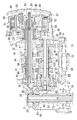
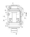
図1は、本発明に係るエンジンのオイル供給構造における一実施形態が適用されたエンジンを搭載する自動二輪車を示す左側面図である。図2は、図1のエンジンの内部を示す断面図である。図3は、図2の一部を拡大して示す断面図である。図4は、図2のエンジンケースを示す斜視図である。   FIG. 1 is a left side view showing a motorcycle equipped with an engine to which an embodiment of an oil supply structure for an engine according to the present invention is applied. FIG. 2 is a cross-sectional view showing the inside of the engine of FIG. FIG. 3 is an enlarged cross-sectional view of a part of FIG. FIG. 4 is a perspective view showing the engine case of FIG.

自動二輪車1は鋼管を主体にしてダブルクレードル型に形成された車体フレーム2を備えており、この車体フレーム2の前半部(ダブルクレードル部分)に前後2気筒のV型エンジン3が搭載され、このV型エンジン3の上方に位置するように燃料タンク4が車体フレーム2上に載置されている。燃料タンク4の後方には着座シート5とリヤカウリング6が順次配置され、V型エンジン3の前下部付近に左右一対のステップ7が設けられている。また、車体フレーム2の前面にはラジエーター8が設置されている。   The motorcycle 1 includes a vehicle body frame 2 mainly formed of a steel pipe and formed in a double cradle type. A V-type engine 3 having two front and rear cylinders is mounted on a front half portion (double cradle portion) of the vehicle body frame 2. A fuel tank 4 is placed on the vehicle body frame 2 so as to be positioned above the V-type engine 3. A seat 5 and a rear cowling 6 are sequentially arranged behind the fuel tank 4, and a pair of left and right steps 7 are provided near the front lower portion of the V-type engine 3. A radiator 8 is installed on the front surface of the vehicle body frame 2.

車体フレーム2の前頭部には前輪9を支持するフロントフォーク10が、ハンドルバー11やヘッドランプ12、フロントフェンダー13等とともに左右回動自在に軸支される。一方、車体フレーム2の中央下部にて車幅方向に架設されたピボット軸15には、車体フレーム2の後半部にて後輪16を支持する三又形状のスイングアーム17が上下回動自在に軸支されている。スイングアーム17の基部付近には後輪懸架装置(不図示)が設けられている。   A front fork 10 that supports a front wheel 9 is pivotally supported on the front head of the vehicle body frame 2 together with a handle bar 11, a headlamp 12, a front fender 13, and the like so as to be rotatable left and right. On the other hand, on a pivot shaft 15 installed in the center lower part of the vehicle body frame 2 in the vehicle width direction, a trifurcated swing arm 17 that supports the rear wheel 16 in the rear half of the vehicle body frame 2 is rotatable up and down. It is pivotally supported. A rear wheel suspension device (not shown) is provided near the base of the swing arm 17.

V型エンジン3は、そのエンジンケース20の上部に車両前後方向に傾斜する前後2つのシリンダ部21F、21Rを備えている。両シリンダ部21F、21Rの挟み角は例えば55°程度の狭角度に設定され、例えばこれらのシリンダ部21F、21Rの上部付近に図示しない吸気装置が配置されている。V型エンジン3の出力は、スイングアーム17の中央アームの内部に挿通されたプロペラシャフト22により、駆動輪としての前記後輪16へ伝達される。   The V-type engine 3 includes two front and rear cylinder portions 21F and 21R that are inclined in the vehicle front-rear direction at the top of the engine case 20. The sandwiching angle between the cylinder portions 21F and 21R is set to a narrow angle of about 55 °, for example, and an intake device (not shown) is disposed near the upper portions of the cylinder portions 21F and 21R, for example. The output of the V-type engine 3 is transmitted to the rear wheel 16 as a drive wheel by a propeller shaft 22 inserted into the center arm of the swing arm 17.

V型エンジン3のエンジンケース20は、図2及び図4に示すように、右側エンジンケース23と左側エンジンケース24とが接合されて構成される左右分割式である。このエンジンケース20は、右側エンジンケース23の前方下部にオイルフィルタ25(図5、図6)が設置されると共に、この右側エンジンケース23の側部にクラッチカバー26が接合される。また、左側エンジンケース24には、側部前寄りにマグネットカバー27が接合されると共に、後部のギヤケース部28に、ベベルギヤユニット64(後述)を覆うギヤケースカバー29が接合されている。   As shown in FIGS. 2 and 4, the engine case 20 of the V-type engine 3 is a left-right split type configured by joining a right engine case 23 and a left engine case 24. In the engine case 20, an oil filter 25 (FIGS. 5 and 6) is installed at a lower front portion of the right engine case 23, and a clutch cover 26 is joined to a side portion of the right engine case 23. In addition, a magnet cover 27 is joined to the left engine case 24 in front of the side, and a gear case cover 29 that covers a bevel gear unit 64 (described later) is joined to the rear gear case part 28.

エンジンケース20内にはクランクシャフト31とカウンタシャフト32とドライブシャフト33が車幅方向に延在し、車両前方側から後方側へ順次平行に配列されている。クランクシャフト31は、複数のメタル軸受34により回転可能に軸支され、カウンタシャフト32とドライブシャフト33は、それぞれ一対のベアリング35、36とベアリング37、38とにより回転可能に軸支されている。   In the engine case 20, a crankshaft 31, a countershaft 32, and a drive shaft 33 extend in the vehicle width direction, and are sequentially arranged in parallel from the vehicle front side to the rear side. The crankshaft 31 is rotatably supported by a plurality of metal bearings 34, and the counter shaft 32 and the drive shaft 33 are rotatably supported by a pair of bearings 35 and 36 and bearings 37 and 38, respectively.

クランクシャフト31の中間部には、2本のコンロッド(不図示)が連設されるクランクピン39とクランクウェブ40とが一体に形成される。このクランクシャフト31の左端には、クランクシャフト31と回転一体のフライホイールマグネット41と、クランクシャフト31と相対回転可能なスタータドリブンギヤ42がそれぞれ設けられ、ワンウェイタイプのスタータクラッチ19を介してスタータドリブンギヤ42がフライホイールマグネット41に連結されている。そして、クランクシャフト31の右端にプライマリードライブギヤ43がプライマリーダンパ44を介して設けられている。   A crank pin 39 and a crank web 40 are integrally formed at an intermediate portion of the crankshaft 31 and two connecting rods (not shown) are continuously provided. At the left end of the crankshaft 31, a flywheel magnet 41 that rotates integrally with the crankshaft 31 and a starter driven gear 42 that can rotate relative to the crankshaft 31 are provided. A starter driven gear 42 is provided via a one-way type starter clutch 19. Is connected to the flywheel magnet 41. A primary drive gear 43 is provided at the right end of the crankshaft 31 via a primary damper 44.

図2及び図3に示すように、カウンタシャフト32の一端側、例えば右側のベアリング36の右側にプライマリードリブンギヤ45がベアリング46を介して回転自在に軸支され、さらにその右側にクラッチ装置47が設けられる。カウンタシャフト32の他端側、例えば左側のベアリング35の付近にクラッチレリーズ機構(不図示)が設けられる。クランクシャフト31に設けられたプライマリードライブギヤ43がプライマリードリブンギヤ45に噛み合っている。   As shown in FIGS. 2 and 3, a primary driven gear 45 is rotatably supported on one end side of the counter shaft 32, for example, the right side of the right bearing 36 via a bearing 46, and a clutch device 47 is provided on the right side thereof. It is done. A clutch release mechanism (not shown) is provided on the other end side of the counter shaft 32, for example, in the vicinity of the left bearing 35. A primary drive gear 43 provided on the crankshaft 31 meshes with a primary driven gear 45.

クラッチ装置47は、自動二輪車用として一般的な多板式クラッチであり、クラッチハウジング48と、クラッチハブ49と、プレッシャープレート50と、複数のドライブプレート51及びドリブンプレート52と、クラッチスプリング53と、クラッチレリーズピース54とを備えて構成されている。   The clutch device 47 is a general multi-plate clutch for a motorcycle, and includes a clutch housing 48, a clutch hub 49, a pressure plate 50, a plurality of drive plates 51 and a driven plate 52, a clutch spring 53, and a clutch. A release piece 54 is provided.

クラッチハウジング48は、複数のクラッチダンパ55と複数のリベットピン56とを介して、プライマリードリブンギヤ45の右側面に回転一体に設けられている。各ドライブプレート51は、クラッチハウジング48の内周に組み込まれてクラッチハウジング48と回転一体かつ軸方向に移動自在に設けられる。   The clutch housing 48 is provided integrally with the right side surface of the primary driven gear 45 via a plurality of clutch dampers 55 and a plurality of rivet pins 56. Each drive plate 51 is incorporated in the inner periphery of the clutch housing 48 and is provided integrally with the clutch housing 48 so as to be rotatable and movable in the axial direction.

一方、クラッチハブ49は、カウンタシャフト32の右端にスプライン30によって回転一体に結合される。各ドリブンプレート52は、クラッチハブ49の外周に組み込まれて、クラッチハブ49と回転一体かつ軸方向に移動自在に設けられる。   On the other hand, the clutch hub 49 is coupled to the right end of the countershaft 32 by the spline 30 so as to be integrally rotated. Each driven plate 52 is incorporated in the outer periphery of the clutch hub 49, and is provided so as to rotate together with the clutch hub 49 and move in the axial direction.

各ドライブプレート51と各ドリブンプレート52は互い違いに重ね合わせられ、クラッチスプリング53に付勢されたプレッシャープレート50により、全てのドライブプレート51とドリブンプレート52がクラッチハブ49側に押え付けられるため、各ドライブプレート51と各ドリブンプレート52間の摩擦力によりクラッチハウジング48とクラッチハブ49が回転一体になり、クランクシャフト31の回転がカウンタシャフト32以降に伝達される。   The drive plates 51 and the driven plates 52 are alternately stacked, and the drive plates 51 and the driven plates 52 are pressed against the clutch hub 49 by the pressure plate 50 biased by the clutch spring 53. The clutch housing 48 and the clutch hub 49 are rotated and integrated by the frictional force between the drive plate 51 and each driven plate 52, and the rotation of the crankshaft 31 is transmitted to the countershaft 32 and later.

図示しないクラッチレリーズ機構は、クラッチレリーズバー57を介してクラッチレリーズロッド58に連結され、このクラッチレリーズロッド58がクラッチレリーズピース54に連結されている。クラッチレリーズロッド58は、カウンタシャフト32内の中空部に挿通される。図1に示すクラッチレバー59が握られると、クラッチレリーズバー57及びクラッチレリーズロッド58を介してクラッチレリーズピース54がクラッチ装置47側(右側)へ移動操作される。   A clutch release mechanism (not shown) is connected to a clutch release rod 58 via a clutch release bar 57, and the clutch release rod 58 is connected to a clutch release piece 54. The clutch release rod 58 is inserted through a hollow portion in the counter shaft 32. When the clutch lever 59 shown in FIG. 1 is gripped, the clutch release piece 54 is moved to the clutch device 47 side (right side) via the clutch release bar 57 and the clutch release rod 58.

すると、クラッチレリーズピース54がクラッチスプリング53の付勢力に抗してプレッシャープレート50を右側に移動させ、各ドライブプレート51と各ドリブンプレート52間の摩擦係合が解かれるのでクラッチ装置47の接続が断たれ、プライマリードリブンギヤ45の回転がカウンタシャフト32に対して遮断される。クラッチレバー59を離せばクラッチ装置47が接続されて、クランクシャフト31の回転が、プライマリードライブギヤ43、プライマリードリブンギヤ45及びクラッチ装置47を経てカウンタシャフト32へ伝達される。   Then, the clutch release piece 54 moves the pressure plate 50 to the right against the urging force of the clutch spring 53, and the friction engagement between each drive plate 51 and each driven plate 52 is released, so that the clutch device 47 is connected. The rotation of the primary driven gear 45 is interrupted with respect to the counter shaft 32. When the clutch lever 59 is released, the clutch device 47 is connected, and the rotation of the crankshaft 31 is transmitted to the counter shaft 32 via the primary drive gear 43, the primary driven gear 45 and the clutch device 47.

カウンタシャフト32を支持する左右のベアリング35、36間に変速ギヤA1〜A5が設けられ、ドライブシャフト33を支持する左右のベアリング37、38間に変速ギヤB1〜B5が設けられる。これらの変速ギヤA1とB1、A2とB2、A3とB3、A4とB4、A5とB5はそれぞれ互いに常時噛み合って、図示しないシフト機構と共に5段変速のトランスミッション機構60を構成している。このトランスミッション機構60の変速操作時には、クラッチ装置47の接続を遮断して変速操作をスムーズにする。   Transmission gears A1 to A5 are provided between the left and right bearings 35 and 36 that support the counter shaft 32, and transmission gears B1 to B5 are provided between the left and right bearings 37 and 38 that support the drive shaft 33. These transmission gears A1 and B1, A2 and B2, A3 and B3, A4 and B4, and A5 and B5 are always meshed with each other to form a five-speed transmission mechanism 60 together with a shift mechanism (not shown). During the speed change operation of the transmission mechanism 60, the clutch device 47 is disconnected to make the speed change operation smooth.

ドライブシャフト33の左端にはベベルドライブギヤ62が回転一体に設けられる。一方、ギヤケース部28及びギヤケースカバー29内には、図2、図3及び図9に示すように、車両前後方向へ延びるドリブンシャフト61が、ベアリング71及び72により回転可能に軸支される。このドリブンシャフト61に、ドライブシャフト33のベベルドライブギヤ62に噛み合うベベルドリブンギヤ63が回転一体に設けられる。これらのドリブンシャフト61、ベベルドライブギヤ62及びベベルドリブンギヤ63を備えてベベルギヤユニット64が構成され、このベベルギヤユニット64がギヤケースカバー29に覆われる。尚、図中の符号73はベベルドリブンギヤ63を位置決めするスペーサーであり、符号74はケースキャップである。   A bevel drive gear 62 is provided at the left end of the drive shaft 33 so as to rotate integrally. On the other hand, a driven shaft 61 extending in the vehicle front-rear direction is rotatably supported by bearings 71 and 72 in the gear case portion 28 and the gear case cover 29 as shown in FIGS. A bevel-driven gear 63 that meshes with the bevel drive gear 62 of the drive shaft 33 is provided on the driven shaft 61 so as to rotate together. The driven shaft 61, the bevel drive gear 62, and the bevel driven gear 63 are provided to form a bevel gear unit 64, and the bevel gear unit 64 is covered with the gear case cover 29. In the figure, reference numeral 73 is a spacer for positioning the bevel driven gear 63, and reference numeral 74 is a case cap.

ドリブンシャフト61は、カップリング65及びユニバーサルジョイント66を介してプロペラシャフト22に回転一体に連結される。このプロペラシャフト22に後輪16がギヤ連結される。従って、V型エンジン3の駆動力、つまりクランクシャフト31の回転力は、クラッチ装置47、カウンタシャフト32、トランスミッション機構60、ドライブシャフト33、ベベルギヤユニット64、ドリブンシャフト61、プロペラシャフト22を順次経て後輪16へ伝達される。このように、トランスミッション機構60から後輪16への動力伝達がプロペラシャフト22を用いてなされる方式は、シャフトドライブ方式と称される。   The driven shaft 61 is rotatably coupled to the propeller shaft 22 via a coupling 65 and a universal joint 66. The rear wheel 16 is geared to the propeller shaft 22. Accordingly, the driving force of the V-type engine 3, that is, the rotational force of the crankshaft 31, passes through the clutch device 47, the counter shaft 32, the transmission mechanism 60, the drive shaft 33, the bevel gear unit 64, the driven shaft 61, and the propeller shaft 22 in order. It is transmitted to the wheel 16. As described above, a system in which power transmission from the transmission mechanism 60 to the rear wheel 16 is performed using the propeller shaft 22 is referred to as a shaft drive system.

一方、図2に示すように、クランクシャフト31の周辺近傍に、エンジン始動装置67が設けられている。このエンジン始動装置67は、スタータモータ68と、スタータアイドルギヤ69と、スタータドライブギヤ70とスタータドリブンギヤ42とを備えて構成され、スタータドライブギヤ70がスタータクラッチ19を介してフライホイールマグネット41に連結されたスタータドリブンギヤ42に噛合する。尚、図4中の符号75は、ウォータポンプを示す。   On the other hand, as shown in FIG. 2, an engine starter 67 is provided in the vicinity of the periphery of the crankshaft 31. The engine starter 67 includes a starter motor 68, a starter idle gear 69, a starter drive gear 70 and a starter driven gear 42, and the starter drive gear 70 is connected to the flywheel magnet 41 via the starter clutch 19. Meshed with the starter-driven gear 42. In addition, the code | symbol 75 in FIG. 4 shows a water pump.

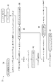
ところで、図11〜図13に示すように、エンジンケース20の下部にはオイル貯溜部としてのオイルパン76が設けられ、V型エンジン3には、このオイルパン76内のオイルをクランクシャフト31、シリンダ部21F、21R、動弁系(不図示)、カウンタシャフト32、ドライブシャフト33及びドリブンシャフト61の各部まで供給して、これらを潤滑するためのオイル通路77が形成されている。以下に、このオイル通路77について詳説する。   Incidentally, as shown in FIGS. 11 to 13, an oil pan 76 as an oil reservoir is provided at the lower part of the engine case 20, and the oil in the oil pan 76 is supplied to the crankshaft 31, the V-type engine 3. An oil passage 77 is formed to supply the cylinder portions 21F and 21R, the valve system (not shown), the counter shaft 32, the drive shaft 33, and the driven shaft 61 to lubricate them. The oil passage 77 will be described in detail below.

つまり、エンジンケース20の下部でカウンタシャフト32の下方位置にウォータポンプ75(図4)と同軸的に配置されて同期駆動されるオイルポンプ78が配置される。これらのオイルポンプ78及びウォータポンプ75は、プライマリードリブンギヤ45(図2、図3)と回転一体に設けられた補機ドライブギヤ79により駆動される。オイルポンプ78の駆動により、オイルパン76内のオイルは、オイルストレーナ80を経て、右側エンジンケース23に形成された右側下オイル通路81(図11、図5)を通りオイルフィルタ25へ至る。   That is, an oil pump 78 that is coaxially arranged with the water pump 75 (FIG. 4) and is driven synchronously is disposed below the counter shaft 32 below the engine case 20. The oil pump 78 and the water pump 75 are driven by an auxiliary machine drive gear 79 provided integrally with the primary driven gear 45 (FIGS. 2 and 3). By driving the oil pump 78, the oil in the oil pan 76 passes through the oil strainer 80, passes through the lower right oil passage 81 (FIGS. 11 and 5) formed in the right engine case 23, and reaches the oil filter 25.

オイルフィルタ25で異物が除去されたオイルは、図11、図12及び図13に示すように、右側エンジンケース23及び左側エンジンケース24を車幅方向に延びるメインギャラリー82を経て、クランクシャフト31のメタル軸受34及びコンロッドとの摺接部(クランクピン39)へ供給されてこれらを潤滑すると共に、シリンダ部21F及び21R内を飛沫潤滑し、更に、メタル軸受34から動弁系へ供給されてこの動弁系を潤滑する。   The oil from which foreign matter has been removed by the oil filter 25 passes through the main gallery 82 extending in the vehicle width direction through the right engine case 23 and the left engine case 24 as shown in FIGS. This is supplied to the sliding contact portion (crank pin 39) with the metal bearing 34 and the connecting rod to lubricate them, and the inside of the cylinder portions 21F and 21R is splash-lubricated, and further supplied from the metal bearing 34 to the valve operating system. Lubricate the valve train.

また、メインギャラリー82に至ったオイルは、図12、図7及び図8に示すように、メインギャラリー82から後方へ略水平に延びる左側第1オイル通路83、上斜め後方へ延びる左側第2オイル通路84を順次流れ、流入孔としての連通孔Aを経て第1オイル溜り部85へ流入し、ここに一旦貯溜される。この第1オイル溜り部85は、図12、図2、図3及び図8に示すように、ギヤケース部28が形成された左側エンジンケース24において、カウンタシャフト32の軸端部(クラッチ装置47が配置された側の軸端部と反対側の軸端部)近傍に円形状に形成される。   Further, as shown in FIGS. 12, 7, and 8, the oil that has reached the main gallery 82 is a left first oil passage 83 that extends substantially horizontally rearward from the main gallery 82, and a left second oil that extends obliquely rearwardly upward. It flows sequentially through the passage 84, flows into the first oil reservoir 85 through the communication hole A as an inflow hole, and is temporarily stored therein. As shown in FIGS. 12, 2, 3, and 8, the first oil reservoir 85 is formed in the left engine case 24 in which the gear case portion 28 is formed. It is formed in a circular shape in the vicinity of the shaft end on the side opposite to the shaft end on the side where it is disposed.

ここで、図12に示すように、左側エンジンケース24に第1オイル溜り部85が対応して形成されるカウンタシャフト32は、オイルポンプ78よりも上方に配置され、このカウンタシャフト32よりも斜め後ろ上方にドライブシャフト33が配置されている。   Here, as shown in FIG. 12, the counter shaft 32 in which the first oil reservoir 85 is formed corresponding to the left engine case 24 is disposed above the oil pump 78, and is inclined more than the counter shaft 32. A drive shaft 33 is disposed on the rear upper side.

第1オイル溜り部85に至ったオイルは、図2及び図3に示すように、カウンタシャフト32の中空部内壁とクラッチレリーズロッド58との間に形成されたカウンタシャフトオイル通路86を通ってベアリング46を潤滑すると共に、トランスミッション機構60の各変速ギヤA1〜A5、B1〜B5の噛み合い部分或いは回転摺動部分を飛沫潤滑等する。   As shown in FIGS. 2 and 3, the oil that has reached the first oil reservoir 85 passes through the countershaft oil passage 86 formed between the hollow portion inner wall of the countershaft 32 and the clutch release rod 58, and then becomes a bearing. 46 is lubricated, and the meshing portions or rotational sliding portions of the transmission gears A1 to A5 and B1 to B5 of the transmission mechanism 60 are splash lubricated.

また、第1オイル溜り部85に至ったオイルは、図12、図7及び図8に示すように、流出孔としての連通孔Bから流出してオイル溝87へ至る。この第1オイル溜り部85では、連通孔Aが連通孔Bよりも高位置に位置づけられている。また、連通孔Bは、第1オイル溜り部85の最下位置より高位置に形成される。更に、オイル溝87は、左側エンジンケース24のギヤケース部28とギヤケースカバー29(図9)との接合面であって、側面視においてドライブシャフト33の下方に形成される。ギヤケース部28の接合面に形成された断面半円形状の溝エレメント88Aと、ギヤケースカバー29の接合面に形成された断面半円形状の溝エレメント88B(図9及び図10)とが組み合わされて、断面円形状のオイル溝87が構成される。   Further, the oil reaching the first oil reservoir 85 flows out from the communication hole B as the outflow hole and reaches the oil groove 87 as shown in FIGS. 12, 7 and 8. In the first oil reservoir 85, the communication hole A is positioned higher than the communication hole B. The communication hole B is formed at a position higher than the lowest position of the first oil reservoir 85. Further, the oil groove 87 is a joint surface between the gear case portion 28 of the left engine case 24 and the gear case cover 29 (FIG. 9), and is formed below the drive shaft 33 in a side view. A groove element 88A having a semicircular cross section formed on the joint surface of the gear case portion 28 and a groove element 88B having a semicircular cross section formed on the joint surface of the gear case cover 29 (FIGS. 9 and 10) are combined. An oil groove 87 having a circular cross section is formed.

図12、図7及び図8に示すように、左側エンジンケース24には、オイル溝87の前方端に、第1オイル溜り部85に連通する前記連通孔Bが形成され、後方端に、後述の第2オイル溜り部89の下部に連通する連通孔Cが形成される。従って、オイル溝87により第1オイル溜り部85と第2オイル溜り部89とが連通する。更にオイル溝87は、連通孔C側が連通孔B側よりも低位置になるように傾斜して形成される。   As shown in FIGS. 12, 7, and 8, the left engine case 24 has the communication hole B communicating with the first oil reservoir 85 at the front end of the oil groove 87, and the rear end is described later. A communication hole C communicating with the lower portion of the second oil reservoir 89 is formed. Accordingly, the first oil reservoir 85 and the second oil reservoir 89 communicate with each other through the oil groove 87. Further, the oil groove 87 is formed to be inclined so that the communication hole C side is positioned lower than the communication hole B side.

オイル溝87に至ったオイルは、連通孔Cを経て第2オイル溜り部89へ流入し、ここに一旦貯溜される。この第2オイル溜り部89は、図2及び図3に示すように、エンジンケース20(右側エンジンケース23及び左側エンジンケース24)の後壁に、ドライブシャフト33と平行に形成される。更に、第2オイル溜り部89は、左端に前記連通孔Cが形成されてオイル溝87に連通され、右端に形成された連通孔Dを経て右側上オイル通路90(図2、図3、図5、図6)に連通される。上記連通孔Cは左側エンジンケース24に形成され、連通孔D及び右側上オイル通路90は、右側エンジンケース23に形成される。そして、第2オイル溜り部89は、連通孔C及びDも含め、図2及び図3に示すようにエンジンケース20の後壁にドライブシャフト33の軸長よりも長く形成される。   The oil that reaches the oil groove 87 flows into the second oil reservoir 89 through the communication hole C, and is temporarily stored therein. As shown in FIGS. 2 and 3, the second oil reservoir 89 is formed on the rear wall of the engine case 20 (the right engine case 23 and the left engine case 24) in parallel with the drive shaft 33. Further, the second oil reservoir 89 has the communication hole C formed at the left end thereof, communicated with the oil groove 87, and the right upper oil passage 90 (FIGS. 2, 3, and 3) through the communication hole D formed at the right end. 5 and FIG. 6). The communication hole C is formed in the left engine case 24, and the communication hole D and the right upper oil passage 90 are formed in the right engine case 23. The second oil reservoir 89, including the communication holes C and D, is formed longer than the axial length of the drive shaft 33 on the rear wall of the engine case 20 as shown in FIGS.

ドライブシャフト33には、内部に軸方向に延びるドライブシャフトオイル通路91が形成される。上記右側上オイル通路90は、第1オイル溜り部85と反対側に位置するドライブシャフト33の端部(右端部)からドライブシャフトオイル通路91に連通される。従って、第2オイル溜り部89に導かれたオイルは、連通孔D及び右側上オイル通路90を経てドライブシャフトオイル通路91内へ供給され、トランスミッション機構60の各変速ギヤA1〜A5、B1〜B5の噛み合い部分或いは回転摺動部分を飛沫潤滑等する。   A drive shaft oil passage 91 extending in the axial direction is formed in the drive shaft 33. The right upper oil passage 90 communicates with the drive shaft oil passage 91 from the end portion (right end portion) of the drive shaft 33 located on the side opposite to the first oil reservoir 85. Accordingly, the oil guided to the second oil reservoir 89 is supplied into the drive shaft oil passage 91 through the communication hole D and the upper right oil passage 90, and the transmission gears A1 to A5 and B1 to B5 of the transmission mechanism 60 are supplied. The meshing part or the rotational sliding part is splashed and lubricated.

一方、図12、図4、図7及び図8に示すように、左側第2オイル通路84に導入されたオイルは、第1オイル溜り部85に連通するための連通孔Aの上方に形成された連通孔Eを経て、ドリブンシャフト61のベアリング71のベアリングオイル溝93へ導かれてこのベアリング71を潤滑すると共に、図2に示すドリブンシャフト61内のドリブンシャフトオイル通路92へ供給されて、ベベルドライブギヤ62とベベルドリブンギヤ63との噛み合い部分を飛沫潤滑する。   On the other hand, as shown in FIGS. 12, 4, 7 and 8, the oil introduced into the left second oil passage 84 is formed above the communication hole A for communicating with the first oil reservoir 85. 2 is guided to the bearing oil groove 93 of the bearing 71 of the driven shaft 61 to lubricate the bearing 71 and supplied to the driven shaft oil passage 92 in the driven shaft 61 shown in FIG. The meshing portion of the drive gear 62 and the bevel driven gear 63 is splash lubricated.

オイル通路77が上述のように構成されたことから、本実施の形態によれば次の効果(1)〜(11)を奏する。   Since the oil passage 77 is configured as described above, the following effects (1) to (11) are achieved according to the present embodiment.

(1)図2及び図3に示すように、左側エンジンケース24のカウンタシャフト32左側軸端部近傍に第1オイル溜り部85を形成したので、エンジン停止時にこの第1オイル溜り部85にオイルを保持することができる。カウンタシャフト32がドライブシャフト33に近接配置され、しかもオイル供給経路上カウンタシャフト32がドライブシャフト33よりも上流側に位置するので、エンジン再始動時に第1オイル溜り部85からドライブシャフト33へ早期にオイルを供給できる。この結果、エンジン再始動時にカウンタシャフト32及びドライブシャフト33へのオイル供給不足を確実に防止できる。   (1) As shown in FIGS. 2 and 3, the first oil reservoir 85 is formed near the left shaft end of the counter shaft 32 of the left engine case 24. Can be held. Since the counter shaft 32 is disposed close to the drive shaft 33, and the counter shaft 32 on the oil supply path is located upstream of the drive shaft 33, the first oil reservoir 85 to the drive shaft 33 at an early stage when the engine is restarted. Oil can be supplied. As a result, insufficient oil supply to the counter shaft 32 and the drive shaft 33 can be reliably prevented when the engine is restarted.

(2)図2及び図3に示すように、シャフトドライブ式自動二輪車のエンジン3においては、ドライブシャフト33の軸方向外方にベベルギヤユニット64が配置されるため、ドライブシャフト33にはベベルギヤユニット64側の軸端部からオイルを供給することは困難である。従って、ベベルギヤユニット64と反対側のドライブシャフト33右側軸端部からオイルを供給することで、ベベルギヤユニット64を所望位置に設けることができる。仮に、ドライブシャフト33にオイルを、ベベルギヤユニット64側の軸端部から供給すると、ベベルギヤユニット64をドライブシャフト33よりも車両後方に配置しなければならない。これにより、プロペラシャフト22のユニバーサルジョイント66も後方に配置されることになるので、スイングアーム17のピボット軸15(図1)とユニバーサルジョイント66とが離間してしまい、後輪16の揺動時の変位を吸収しきれなくなる恐れがあるが、これを防止できる。   (2) As shown in FIG. 2 and FIG. 3, in the engine 3 of the shaft drive type motorcycle, the bevel gear unit 64 is disposed outside the drive shaft 33 in the axial direction. It is difficult to supply oil from the side shaft end. Therefore, the bevel gear unit 64 can be provided at a desired position by supplying oil from the right shaft end of the drive shaft 33 opposite to the bevel gear unit 64. If oil is supplied to the drive shaft 33 from the shaft end on the bevel gear unit 64 side, the bevel gear unit 64 must be disposed behind the drive shaft 33 in the vehicle. As a result, the universal joint 66 of the propeller shaft 22 is also disposed rearward, so that the pivot shaft 15 (FIG. 1) of the swing arm 17 and the universal joint 66 are separated from each other, and the rear wheel 16 is swung. However, this can be prevented.

(3)図2及び図3に示すように、ベベルギヤユニット64は、クラッチ装置47と反対側の左側エンジンケース24の側面に配置されるので、クラッチ装置47と干渉することがなく、この干渉を回避するためにエンジンケース20を車両外方へ張り出させる必要もなく、しかも、左側エンジンケース24のベベルギヤユニット64側に形成される第1オイル溜り部85の容量も良好に確保できる。   (3) As shown in FIGS. 2 and 3, the bevel gear unit 64 is disposed on the side surface of the left engine case 24 opposite to the clutch device 47, so that the interference does not interfere with the clutch device 47. In order to avoid this, it is not necessary to project the engine case 20 to the outside of the vehicle, and the capacity of the first oil reservoir 85 formed on the bevel gear unit 64 side of the left engine case 24 can be secured well.

(4)図11及び図12に示すように、エンジン3の高さ方向において、ドライブシャフト33とオイルポンプ78との間に第1オイル溜り部85及び第2オイル溜り部89が設けられるので、エンジン3の停止時にオイルが、ドライブシャフト33のドライブシャフトオイル通路91(図2及び図3)から自重で第2オイル溜り部89及び第1オイル溜り部85に溜り、オイルパン76へ戻ることを回避できる。   (4) As shown in FIGS. 11 and 12, since the first oil reservoir 85 and the second oil reservoir 89 are provided between the drive shaft 33 and the oil pump 78 in the height direction of the engine 3, When the engine 3 is stopped, the oil is accumulated in the second oil reservoir 89 and the first oil reservoir 85 by its own weight from the drive shaft oil passage 91 (FIGS. 2 and 3) of the drive shaft 33 and returns to the oil pan 76. Can be avoided.

(5)図2、図3及び図12に示すように、ドライブシャフト33のドライブシャフトオイル通路91内へは、主にオイル溝87、第2オイル溜り部89及び右側上オイル通路90のオイル通路を経て、ベベルギヤユニット64が存在しないドライブシャフト33右側端部からオイルを供給するので、オイル通路がベベルギヤユニット64と干渉することを防止できると共に、オイル通路の構造も簡素化できる。   (5) As shown in FIGS. 2, 3, and 12, mainly into the drive shaft oil passage 91 of the drive shaft 33, the oil groove 87, the second oil reservoir 89, and the oil passage of the right upper oil passage 90. Then, oil is supplied from the right end of the drive shaft 33 where the bevel gear unit 64 does not exist, so that the oil passage can be prevented from interfering with the bevel gear unit 64 and the structure of the oil passage can be simplified.

(6)図12に示すように、エンジン3の停止時には、第1オイル溜り部85内のオイルが自重により連通孔A(流入孔)から左側第2オイル通路84を介してオイルパン76まで逆流してしまうことがある。仮に、第1オイル溜り部85における連通孔Aが連通孔B(流出孔)よりも低い位置に設けられると、エンジン停止時に第1オイル溜り部85で保持できるオイル量が減少してしまう。これに対し、本実施の形態では、第1オイル溜り部85における連通孔Aが連通孔Bよりも高位置に設けられているので、エンジン停止時における第1オイル溜り部85内のオイル量を良好に保持できる。   (6) As shown in FIG. 12, when the engine 3 is stopped, the oil in the first oil reservoir 85 flows back from the communication hole A (inflow hole) to the oil pan 76 through the left second oil passage 84 due to its own weight. May end up. If the communication hole A in the first oil reservoir 85 is provided at a position lower than the communication hole B (outflow hole), the amount of oil that can be held by the first oil reservoir 85 is reduced when the engine is stopped. In contrast, in the present embodiment, since the communication hole A in the first oil reservoir 85 is provided at a higher position than the communication hole B, the amount of oil in the first oil reservoir 85 when the engine is stopped is reduced. It can be held well.

(7)図11及び図12に示すように、第1オイル溜り部85とは別に第2オイル溜り部89を備えたので、オイル通路77におけるオイルの貯溜容量を増大できる。しかも、第1オイル溜り部85よりもドライブシャフト33に近接させて第2オイル溜り部89が設けられたので、ドライブシャフト33へのエンジン再始動時におけるオイル供給応答性を一層良好にすることができる。   (7) As shown in FIGS. 11 and 12, since the second oil reservoir 89 is provided separately from the first oil reservoir 85, the oil storage capacity in the oil passage 77 can be increased. In addition, since the second oil reservoir 89 is provided closer to the drive shaft 33 than the first oil reservoir 85, the oil supply response to the drive shaft 33 when the engine is restarted can be further improved. it can.

(8)図2及び図3に示すように、第2オイル溜り部89がエンジンケース20の後壁にドライブシャフト33と平行に形成されたので、オイル通路77は、この第2オイル溜り部89によってドライブシャフト33を軸方向に跨ぐことになり、この第2オイル溜り部89の容量を確保できると共に、ベベルギヤユニット64と反対側のドライブシャフト33右側軸端部からドライブシャフトオイル通路91へオイルを供給することができる。   (8) As shown in FIGS. 2 and 3, since the second oil reservoir 89 is formed on the rear wall of the engine case 20 in parallel with the drive shaft 33, the oil passage 77 is connected to the second oil reservoir 89. As a result, the drive shaft 33 is straddled in the axial direction, the capacity of the second oil reservoir 89 can be secured, and oil can be supplied from the right shaft end of the drive shaft 33 opposite to the bevel gear unit 64 to the drive shaft oil passage 91. Can be supplied.

(9)図2及び図3に示すように、第2オイル溜り部89が、連通孔C及びDも含めてドライブシャフト33の軸長よりも長く形成されたので、その分、第2オイル溜り部89の容量を増大させることができる。   (9) As shown in FIGS. 2 and 3, since the second oil reservoir 89 is formed longer than the axial length of the drive shaft 33 including the communication holes C and D, the second oil reservoir 89 is correspondingly increased. The capacity of the part 89 can be increased.

(10)図12に示すように、第1オイル溜り部85と第2オイル溜り部89とを連通するオイル溝87は、第2オイル溜り部89側の連通孔Cが第1オイル溜り部85側の連通孔Bよりも低位置になるよう傾斜して形成されたので、第2オイル溜り部89内のオイルが第1オイル溜り部85内へ逆流することを抑制でき、この結果、第2オイル溜り部89内でのオイル貯溜量を良好に確保できる。   (10) As shown in FIG. 12, the oil groove 87 communicating the first oil reservoir 85 and the second oil reservoir 89 has a communication hole C on the second oil reservoir 89 side so that the first oil reservoir 85 is connected. Since it is formed so as to be lower than the communication hole B on the side, the oil in the second oil reservoir 89 can be prevented from flowing back into the first oil reservoir 85. As a result, the second An oil storage amount in the oil reservoir 89 can be secured satisfactorily.

(11)図7及び図9に示すように、オイル溝87は、左側エンジンケース24のギヤケース部28とギヤケースカバー29との接合面にそれぞれ形成された溝エレメント88Aと88Bとが組み合わされて構成されるので、このオイル溝87の加工性を向上でき、しかもオイル溝87を、別部品を用いることなくエンジンケース20と一体に形成することができる。   (11) As shown in FIGS. 7 and 9, the oil groove 87 is configured by combining groove elements 88 </ b> A and 88 </ b> B respectively formed on the joint surface between the gear case portion 28 of the left engine case 24 and the gear case cover 29. Therefore, the workability of the oil groove 87 can be improved, and the oil groove 87 can be formed integrally with the engine case 20 without using a separate part.

以上、本発明を上記実施の形態に基づいて説明したが、本発明はこれに限定されるものではない。例えば、本実施の形態のオイル通路77は、シャフトドライブ式自動二輪車のエンジンに限らず、それ以外のエンジンのオイル通路にも適用できる。   As mentioned above, although this invention was demonstrated based on the said embodiment, this invention is not limited to this. For example, the oil passage 77 of the present embodiment can be applied not only to an engine of a shaft drive type motorcycle but also to an oil passage of other engines.

本発明に係るエンジンのオイル供給構造における一実施形態が適用されたエンジンを搭載する自動二輪車を示す左側面図。1 is a left side view showing a motorcycle equipped with an engine to which an embodiment of an oil supply structure for an engine according to the present invention is applied. 図1のエンジンの内部を示す断面図。Sectional drawing which shows the inside of the engine of FIG. 図2の一部を拡大して示す断面図。Sectional drawing which expands and shows a part of FIG. 図2のエンジンケースを示す斜視図。The perspective view which shows the engine case of FIG. 図4の右側エンジンケースの外面を示す正面図。The front view which shows the outer surface of the right side engine case of FIG. 図5の右側エンジンケースの内面を示す背面図。The rear view which shows the inner surface of the right side engine case of FIG. 図4の左側エンジンケースの外面を示す正面図。The front view which shows the outer surface of the left side engine case of FIG. 図7の左側エンジンケースの内面を示す背面図。The rear view which shows the inner surface of the left engine case of FIG. 図2のギヤケースカバーの内面を示す背面図。The rear view which shows the inner surface of the gear case cover of FIG. 図9のX−X線に沿うギヤケースカバーのみの断面図。Sectional drawing of only the gear case cover which follows the XX line of FIG. 図5の右側エンジンケースの外面にオイル通路を模式的に示した正面図。FIG. 6 is a front view schematically showing an oil passage on the outer surface of the right engine case of FIG. 5. 図7の左側エンジンケースの外面にオイル通路を模式的に示した正面図。The front view which showed the oil path typically on the outer surface of the left engine case of FIG. 主に図11及び図12に示すオイル通路を流れるオイルの経路を示す経路図。FIG. 13 is a route diagram showing a route of oil mainly flowing through the oil passage shown in FIGS. 11 and 12.

符号の説明Explanation of symbols

1 自動二輪車
3 V型エンジン
16 後輪(駆動輪)
20 エンジンケース
22 プロペラシャフト
23 右側エンジンケース
24 左側エンジンケース
25 オイルフィルタ
28 ギヤケース部
29 ギヤケースカバー
31 クランクシャフト
32 カウンタシャフト
33 ドライブシャフト
43 プライマリードライブギヤ
45 プライマリードリブンギヤ
47 クラッチ装置
61 ドリブンシャフト
62 ベベルドライブギヤ
63 ベベルドリブンギヤ
64 ベベルギヤユニット
76 オイルパン
77 オイル通路
78 オイルポンプ
82 メインギャラリー
85 第1オイル溜り部
87 オイル溝
89 第2オイル溜り部
91 ドライブシャフトオイル通路
A 連通孔(流入孔)
B 連通孔(流出孔)
1 Motorcycle 3 V-type engine 16 Rear wheel (drive wheel)
20 Engine case 22 Propeller shaft 23 Right engine case 24 Left engine case 25 Oil filter 28 Gear case 29 Gear case cover 31 Crankshaft 32 Countershaft 33 Driveshaft 43 Primary drive gear 45 Primary driven gear 47 Clutch device 61 Driven shaft 62 Bevel drive gear 63 Bevel driven gear 64 Bevel gear unit 76 Oil pan 77 Oil passage 78 Oil pump 82 Main gallery 85 First oil reservoir 87 Oil groove 89 Second oil reservoir 91 Drive shaft oil passage A Communication hole (inflow hole)
B Communication hole (outflow hole)

Claims (10)

シャフトドライブ式の自動二輪車のエンジンであって、
このエンジンは、
エンジンケースの内部に互いに平行なクランクシャフト、カウンタシャフト及びドライブシャフトが順次配置されると共に、それぞれのシャフトが回転可能に支持され、
前記ドライブシャフトにベベルドライブギヤが回転一体に設けられ、
このベベルドライブギヤに噛み合うベベルドリブンギヤを回転一体に備えたプロペラシャフトを介して、前記エンジンの動力を駆動輪へ伝達すると共に、オイルポンプから前記ドライブシャフトまでオイルを供給するオイル通路を有し、
このオイル通路は、前記ベベルドライブギヤ及び前記ベベルドリブンギヤが配置される側の前記カウンタシャフトの軸端部近傍に第1オイル溜り部を備え、この第1オイル溜り部を経て前記ドライブシャフトへオイルを導くよう構成されたことを特徴とするエンジンのオイル供給構造。
A shaft drive type motorcycle engine,
This engine
A crankshaft, a counter shaft and a drive shaft parallel to each other are sequentially arranged inside the engine case, and each shaft is rotatably supported.
A bevel drive gear is provided integrally with the drive shaft.
An oil passage that transmits the power of the engine to a drive wheel through a propeller shaft that is integrally provided with a bevel driven gear that meshes with the bevel drive gear, and that supplies oil from an oil pump to the drive shaft;
The oil passage includes a first oil reservoir near the shaft end of the counter shaft on the side where the bevel drive gear and the bevel driven gear are arranged, and oil is supplied to the drive shaft through the first oil reservoir. Engine oil supply structure characterized by being configured to guide.
前記カウンタシャフトがオイルポンプよりも高位置に配置され、このカウンタシャフトよりも高位置にドライブシャフトが配置されたことを特徴とする請求項1に記載のエンジンのオイル供給構造。 The engine oil supply structure according to claim 1, wherein the counter shaft is disposed at a position higher than the oil pump, and a drive shaft is disposed at a position higher than the counter shaft. 前記ドライブシャフトの内部にドライブシャフトオイル通路が形成され、オイル通路は、第1オイル溜り部と反対側に位置する前記ドライブシャフトの端部から前記ドライブシャフトオイル通路内へオイルを導くよう構成されたことを特徴とする請求項1に記載のエンジンのオイル供給構造。 A drive shaft oil passage is formed in the drive shaft, and the oil passage is configured to guide oil into the drive shaft oil passage from an end portion of the drive shaft located on the side opposite to the first oil reservoir. The oil supply structure for an engine according to claim 1. 前記オイル通路は、第1オイル溜り部へオイルを流入させる流入孔と、前記第1オイル溜り部からオイルを流出させる流出孔とを備え、前記流入孔が前記流出孔よりも高位置に位置づけられたことを特徴とする請求項1に記載のエンジンのオイル供給構造。 The oil passage includes an inflow hole through which oil flows into the first oil reservoir and an outflow hole through which oil flows out from the first oil reservoir, and the inflow hole is positioned higher than the outflow hole. The engine oil supply structure according to claim 1, wherein 前記オイル通路は、第1オイル溜り部と前記ドライブシャフトとの間に、前記第1オイル溜り部とは別に第2オイル溜り部を備えたことを特徴とする請求項1に記載のエンジンのオイル供給構造。 2. The engine oil according to claim 1, wherein the oil passage includes a second oil reservoir separately from the first oil reservoir between the first oil reservoir and the drive shaft. Supply structure. 前記第2オイル溜り部は、エンジンケースの後壁に、ドライブシャフトと平行に形成されたことを特徴とする請求項5に記載のエンジンのオイル供給構造。 The engine oil supply structure according to claim 5, wherein the second oil reservoir is formed on a rear wall of the engine case in parallel with the drive shaft. 前記第2オイル溜り部は、エンジンケースの後壁に、ドライブシャフトの軸長よりも長く形成されたことを特徴とする請求項6に記載のエンジンのオイル供給構造。 The engine oil supply structure according to claim 6, wherein the second oil reservoir is formed on the rear wall of the engine case so as to be longer than the axial length of the drive shaft. 前記オイル通路は、側面視においてドライブシャフトの下方を通り、第1オイル溜り部の流出孔と第2オイル溜り部とを連通するオイル溝を備え、このオイル溝は、前記第2オイル溜り部側が前記流出孔側よりも低位置になるように傾斜して形成されたことを特徴とする請求項5に記載のエンジンのオイル供給構造。 The oil passage includes an oil groove that passes under the drive shaft in a side view and communicates the outflow hole of the first oil reservoir and the second oil reservoir, and the oil groove is located on the second oil reservoir side. The engine oil supply structure according to claim 5, wherein the engine oil supply structure is formed so as to be inclined at a lower position than the outflow hole side. 前記オイル溝は、ベベルドライブギヤ及びベベルドリブンギヤを覆うギヤケースカバーと、このギヤケースカバーが接合されるエンジンケースのギヤケース部との接合面に形成されたことを特徴とする請求項8に記載のエンジンのオイル供給構造。 9. The engine according to claim 8, wherein the oil groove is formed on a joint surface between a gear case cover that covers the bevel drive gear and the bevel driven gear and a gear case portion of an engine case to which the gear case cover is joined. Oil supply structure. シャフトドライブ式の自動二輪車のエンジンであって、
このエンジンは、
エンジンケースの内部に互いに平行なクランクシャフト、カウンタシャフト及びドライブシャフトが順次配置されると共に、それぞれのシャフトが回転可能に支持され、
前記ドライブシャフトにベベルドライブギヤが回転一体に設けられ、
このベベルドライブギヤに噛合うベベルドリブンギヤを回転一体に備えたプロペラシャフトを介して、前記エンジンの動力を駆動輪へ伝達すると共に、オイルポンプから前記ドライブシャフトまでオイルを供給するオイル通路を有し、
前記ベベルドライブギヤ及び前記ベベルドリブンギヤを含んで構成されるベベルギヤユニットが、前記オイルポンプよりも高位置で前記エンジンケースの側部に配置され、
前記オイル通路は、前記ベベルギヤユニットが配置される側の前記カウンタシャフトの軸端部近傍に第1オイル溜り部を備え、この第1オイル溜り部を経て、前記ベベルギヤユニットと反対側に位置する前記ドライブシャフトの端部へオイルを導くよう構成されたことを特徴とするエンジンのオイル供給構造。
A shaft drive type motorcycle engine,
This engine
A crankshaft, a counter shaft and a drive shaft parallel to each other are sequentially arranged inside the engine case, and each shaft is rotatably supported.
A bevel drive gear is provided integrally with the drive shaft.
Through the propeller shaft that is integrally provided with a bevel driven gear that meshes with the bevel drive gear, the power of the engine is transmitted to the drive wheel, and an oil passage that supplies oil from an oil pump to the drive shaft is provided.
A bevel gear unit configured to include the bevel drive gear and the bevel driven gear is disposed at a side of the engine case at a position higher than the oil pump;
The oil passage includes a first oil reservoir near the shaft end of the counter shaft on the side where the bevel gear unit is disposed, and the oil passage is located on the opposite side of the bevel gear unit via the first oil reservoir. An oil supply structure for an engine characterized by being configured to guide oil to an end of a drive shaft.
JP2008171630A 2008-06-30 2008-06-30 Engine oil supply structure Active JP5286976B2 (en)

Priority Applications (1)

Application Number Priority Date Filing Date Title
JP2008171630A JP5286976B2 (en) 2008-06-30 2008-06-30 Engine oil supply structure

Applications Claiming Priority (1)

Application Number Priority Date Filing Date Title
JP2008171630A JP5286976B2 (en) 2008-06-30 2008-06-30 Engine oil supply structure

Publications (2)

Publication Number Publication Date
JP2010007847A true JP2010007847A (en) 2010-01-14
JP5286976B2 JP5286976B2 (en) 2013-09-11

Family

ID=41588580

Family Applications (1)

Application Number Title Priority Date Filing Date
JP2008171630A Active JP5286976B2 (en) 2008-06-30 2008-06-30 Engine oil supply structure

Country Status (1)

Country Link
JP (1) JP5286976B2 (en)

Cited By (4)

* Cited by examiner, † Cited by third party
Publication number Priority date Publication date Assignee Title
CN102840312A (en) * 2011-06-20 2012-12-26 特纳动力系统有限公司 Gearbox split sump
EP2806121A2 (en) 2013-05-23 2014-11-26 Yamaha Hatsudoki Kabushiki Kaisha Motorcycle
JP5644853B2 (en) * 2010-04-22 2014-12-24 スズキ株式会社 Engine oil passage structure
JP2020029836A (en) * 2018-08-24 2020-02-27 トヨタ自動車株式会社 Chain case

Citations (6)

* Cited by examiner, † Cited by third party
Publication number Priority date Publication date Assignee Title
JPS55132454U (en) * 1979-03-09 1980-09-19
JPS6236127B2 (en) * 1979-10-29 1987-08-05 Yamaha Motor Co Ltd
JPS62209267A (en) * 1986-03-06 1987-09-14 Yamaha Motor Co Ltd Lubricating system of change gear for vehicle
JPS637736Y2 (en) * 1984-03-08 1988-03-07
JPH0514035Y2 (en) * 1987-02-20 1993-04-14
JP2008111539A (en) * 2006-10-31 2008-05-15 Kawasaki Heavy Ind Ltd Shaft drive type vehicle

Patent Citations (6)

* Cited by examiner, † Cited by third party
Publication number Priority date Publication date Assignee Title
JPS55132454U (en) * 1979-03-09 1980-09-19
JPS6236127B2 (en) * 1979-10-29 1987-08-05 Yamaha Motor Co Ltd
JPS637736Y2 (en) * 1984-03-08 1988-03-07
JPS62209267A (en) * 1986-03-06 1987-09-14 Yamaha Motor Co Ltd Lubricating system of change gear for vehicle
JPH0514035Y2 (en) * 1987-02-20 1993-04-14
JP2008111539A (en) * 2006-10-31 2008-05-15 Kawasaki Heavy Ind Ltd Shaft drive type vehicle

Cited By (5)

* Cited by examiner, † Cited by third party
Publication number Priority date Publication date Assignee Title
JP5644853B2 (en) * 2010-04-22 2014-12-24 スズキ株式会社 Engine oil passage structure
CN102840312A (en) * 2011-06-20 2012-12-26 特纳动力系统有限公司 Gearbox split sump
EP2806121A2 (en) 2013-05-23 2014-11-26 Yamaha Hatsudoki Kabushiki Kaisha Motorcycle
JP2020029836A (en) * 2018-08-24 2020-02-27 トヨタ自動車株式会社 Chain case
JP7014097B2 (en) 2018-08-24 2022-02-01 トヨタ自動車株式会社 Chain case

Also Published As

Publication number Publication date
JP5286976B2 (en) 2013-09-11

Similar Documents

Publication Publication Date Title
JP4397927B2 (en) Motorcycle engine
JP4906455B2 (en) Crankcase structure of internal combustion engine
JP2008274976A (en) Motorcycle power unit
JP2009002272A (en) Power unit for motorcycle
JP2013083215A (en) Oil passage structure
JP4451437B2 (en) Power unit for motorcycle
JP5286976B2 (en) Engine oil supply structure
JP2009243437A (en) Lubricating device for internal combustion engine
JP6194762B2 (en) Transmission lubrication structure for motorcycles
JP5190430B2 (en) Always open clutch structure
JP4580856B2 (en) Scooter type vehicle
JP5921403B2 (en) Engine lubrication structure
JP2008075713A (en) Vehicle engine
JP4622776B2 (en) Oil pump structure
JP2006105131A (en) Engine for motorcycle
JP5848738B2 (en) Internal combustion engine
JP4781335B2 (en) On-vehicle power unit
JP4878853B2 (en) Internal combustion engine
JP5351587B2 (en) Internal combustion engine for small vehicles
JP6156106B2 (en) Outboard motor
JP4105057B2 (en) Internal combustion engine with starter motor
JP2005308001A (en) Balancer device for engine
JP5601278B2 (en) Drive transmission lubrication structure
KR101210212B1 (en) Internal combustion engine with kick-type starter
JP5219883B2 (en) Starter motor arrangement structure of internal combustion engine

Legal Events

Date Code Title Description
A621 Written request for application examination

Free format text: JAPANESE INTERMEDIATE CODE: A621

Effective date: 20110329

A977 Report on retrieval

Free format text: JAPANESE INTERMEDIATE CODE: A971007

Effective date: 20120425

A131 Notification of reasons for refusal

Free format text: JAPANESE INTERMEDIATE CODE: A131

Effective date: 20120508

A521 Written amendment

Free format text: JAPANESE INTERMEDIATE CODE: A523

Effective date: 20120709

RD02 Notification of acceptance of power of attorney

Free format text: JAPANESE INTERMEDIATE CODE: A7422

Effective date: 20120709

A131 Notification of reasons for refusal

Free format text: JAPANESE INTERMEDIATE CODE: A131

Effective date: 20130205

A521 Written amendment

Free format text: JAPANESE INTERMEDIATE CODE: A523

Effective date: 20130306

TRDD Decision of grant or rejection written
A01 Written decision to grant a patent or to grant a registration (utility model)

Free format text: JAPANESE INTERMEDIATE CODE: A01

Effective date: 20130507

A61 First payment of annual fees (during grant procedure)

Free format text: JAPANESE INTERMEDIATE CODE: A61

Effective date: 20130520

R151 Written notification of patent or utility model registration

Ref document number: 5286976

Country of ref document: JP

Free format text: JAPANESE INTERMEDIATE CODE: R151