JP2010007499A - Control device and control method for vehicle engine - Google Patents
Control device and control method for vehicle engine Download PDFInfo
- Publication number
- JP2010007499A JP2010007499A JP2008165062A JP2008165062A JP2010007499A JP 2010007499 A JP2010007499 A JP 2010007499A JP 2008165062 A JP2008165062 A JP 2008165062A JP 2008165062 A JP2008165062 A JP 2008165062A JP 2010007499 A JP2010007499 A JP 2010007499A
- Authority
- JP
- Japan
- Prior art keywords
- ignition
- spark plug
- control
- air
- fuel mixture
- Prior art date
- Legal status (The legal status is an assumption and is not a legal conclusion. Google has not performed a legal analysis and makes no representation as to the accuracy of the status listed.)
- Granted
Links
Images


Abstract
Description
本発明は、車両用エンジンの燃焼室内の混合気を点火する制御技術に関する。 The present invention relates to a control technique for igniting an air-fuel mixture in a combustion chamber of a vehicle engine.
車両用エンジンの燃焼室内の混合気を点火する技術として、2つの点火プラグを用いる技術がある。例えば、特許文献1では、機関温度が所定値以下であり、かつ、機関回転数の変動量が所定値以下である場合に、2個の点火プラグのうち片方のみの点火プラグを作動させ、機関温度が所定値以下であり、かつ、機関回転数の変動量が所定値よりも大きい場合には両方の点火プラグを作動させる技術が開示されている。
ここで、発進・加速時のタイヤの空転を防止するトラクションコントロールシステム(TCS)によるトルクダウンや自動変速機のギアチェンジの際に行われる変速トルクダウンのように、ドライバの操作に起因しないトルクダウン要求が入力された際には、点火プラグによる点火タイミングを遅らせることにより、トルクを下げる手法(一般に点火リタードと呼ばれる。)が用いられている。 Here, torque reduction that is not caused by the driver's operation, such as torque reduction by traction control system (TCS) that prevents tire slippage at start-up and acceleration, and gearshift torquedown that is performed at the time of gear change of automatic transmission When a request is input, a method of reducing torque by delaying the ignition timing by the spark plug (generally called ignition retard) is used.
しかしながら、点火リタードによってトルクを下げた場合には、排気温度が上昇するため、一酸化炭素(CO)、炭化水素(HC)、窒素酸化物(NOx)等の人体に有害な物質を除去する触媒コンバータの処理可能な適正温度範囲を超えてしまい、当該有害物質の除去効率が低下してしまう。 However, when the torque is reduced by ignition retard, the exhaust temperature rises, so a catalyst that removes substances harmful to the human body such as carbon monoxide (CO), hydrocarbon (HC), nitrogen oxide (NOx), etc. Exceeding the appropriate temperature range that can be handled by the converter, the removal efficiency of the harmful substances will be reduced.
この点、特許文献1に開示された技術では、ドライバの操作に起因しないトルクダウン要求により点火リタードが行われた場合であっても、それぞれの点火プラグの位置を考慮することなく、点火プラグの点火数のみを制御するため、上述と同様に、排気温度の上昇により触媒コンバータの適正温度範囲を超えてしまう可能性がある。 In this regard, in the technique disclosed in Patent Document 1, even when ignition retard is performed due to a torque down request not caused by the operation of the driver, the ignition plug is not considered without considering the position of each ignition plug. Since only the number of ignitions is controlled, there is a possibility that the temperature range of the catalytic converter may be exceeded due to an increase in exhaust gas temperature as described above.
従って、本発明の目的は、点火リタード量を低減しながら所望のトルクダウンを行うことにより、排気温度の上昇を抑制して排気中に含まれる有害物質の除去効率の低下を抑制することにある。 Accordingly, an object of the present invention is to suppress a decrease in the removal efficiency of harmful substances contained in exhaust gas by suppressing a rise in exhaust gas temperature by performing a desired torque reduction while reducing the amount of ignition retard. .
上記課題を解決するため、本発明においては、気筒の略中心線上に点火点が設定された第1点火プラグと、前記第1点火プラグの前記点火点から離間した位置に点火点が設定された第2点火プラグと、を各気筒毎に備えた車両用エンジンの制御装置において、車両のドライバの操作に起因しない予め定めた自動トルクダウン条件が成立したか否かを判定する判定手段と、前記判定手段が前記自動トルクダウン条件が成立していないと判定した場合は、少なくとも前記第1点火プラグにより燃焼室内の混合気を点火する第1点火制御を行い、前記判定手段が前記自動トルクダウン条件が成立したと判定した場合は前記第2点火プラグのみにより前記混合気を点火する第2点火制御を行う点火制御手段と、を備えたことを特徴とする制御装置が提供される。 In order to solve the above-described problem, in the present invention, the ignition point is set at a position apart from the first ignition plug in which the ignition point is set on a substantially center line of the cylinder, and the first ignition plug. A determination means for determining whether or not a predetermined automatic torque-down condition not caused by an operation of a driver of the vehicle is satisfied in a control device for a vehicle engine provided with a second spark plug for each cylinder; When the determination means determines that the automatic torque reduction condition is not satisfied, at least first ignition control is performed to ignite the air-fuel mixture in the combustion chamber by the first spark plug, and the determination means performs the automatic torque reduction condition. And an ignition control means for performing second ignition control for igniting the air-fuel mixture only by the second spark plug when it is determined that is established. It is.
また、本発明においては、気筒の略中心線上に点火点が設定された第1点火プラグと、前記第1点火プラグの前記点火点から離間した位置に点火点が設定された第2点火プラグと、を各気筒毎に備えた車両用エンジンの制御方法において、車両のドライバの操作に起因しない予め定めた自動トルクダウン条件が成立したか否かを判定する判定工程と、前記判定工程が前記自動トルクダウン条件が成立していないと判定した場合は、少なくとも前記第1点火プラグにより燃焼室内の混合気を点火する第1点火制御を行い、前記判定工程が前記自動トルクダウン条件が成立したと判定した場合は前記第2点火プラグのみにより前記混合気を点火する第2点火制御を行う点火制御工程と、を有することを特徴とする制御方法が提供される。 In the present invention, a first spark plug whose ignition point is set on a substantially center line of the cylinder, and a second spark plug whose ignition point is set at a position away from the ignition point of the first spark plug; In the vehicle engine control method provided for each cylinder, a determination step for determining whether or not a predetermined automatic torque-down condition not caused by an operation of a driver of the vehicle is satisfied, and the determination step includes the automatic If it is determined that the torque-down condition is not satisfied, at least first ignition control is performed to ignite the air-fuel mixture in the combustion chamber by the first spark plug, and the determination step determines that the automatic torque-down condition is satisfied In this case, there is provided an ignition control step for performing a second ignition control for igniting the air-fuel mixture only by the second ignition plug.
本発明に係る車両用エンジンの制御装置及び制御方法によれば、前記自動トルクダウン条件が成立していないと判定した場合に、少なくとも第1点火プラグにより燃焼室内の混合気を点火するため、前記燃焼室内の側面で混合気が冷却されることによるエネルギ損失を低減することができる。このため、前記混合気の燃焼により得られるエネルギを効率よく用いることができる。一方、前記自動トルクダウン条件が成立したと判定した場合に、前記第2点火プラグのみにより前記混合気を点火するため、前記燃焼室の側面に近接する位置で点火されることになり、前記燃焼室の側面で混合気が冷却されることによって、より大きなエネルギ損失が生じることとなる。このため、排気温度の上昇を抑制して排気中に含まれる有害物質の除去効率の低下を抑制することができる。 According to the control device and the control method for a vehicle engine according to the present invention, when it is determined that the automatic torque down condition is not satisfied, at least the first spark plug ignites the air-fuel mixture in the combustion chamber. Energy loss due to the air-fuel mixture being cooled on the side surface in the combustion chamber can be reduced. For this reason, the energy obtained by the combustion of the air-fuel mixture can be used efficiently. On the other hand, when it is determined that the automatic torque down condition is satisfied, the air-fuel mixture is ignited only by the second spark plug, so that the ignition is performed at a position close to the side surface of the combustion chamber. As the air-fuel mixture is cooled at the side of the chamber, a greater energy loss will occur. For this reason, the rise in exhaust temperature can be suppressed and the fall of the removal efficiency of the harmful substance contained in exhaust can be suppressed.
また、本発明においては、前記点火制御手段は、前記第1点火制御においては前記第1点火プラグのみにより前記混合気を点火し、かつ、前記第2点火制御においては、前記第1点火制御よりも、点火タイミングを遅角させる構成としてもよい。この構成によれば、前記点火制御手段は、前記第2点火制御における前記第2点火プラグの点火タイミングを前記第1点火制御における前記第1点火プラグの点火タイミングよりも遅角させるため、前記トルクダウンをより確実に行うことができる。 In the present invention, the ignition control means ignites the air-fuel mixture only with the first spark plug in the first ignition control, and moreover than the first ignition control in the second ignition control. Alternatively, the ignition timing may be retarded. According to this configuration, the ignition control means retards the ignition timing of the second spark plug in the second ignition control from the ignition timing of the first spark plug in the first ignition control. Down can be performed more reliably.
また、本発明においては、前記点火制御手段は、前記第1点火制御においては前記第1及び第2点火プラグにより前記混合気を点火し、かつ、前記第2点火制御においては、前記第1点火制御における前記第1及び第2点火プラグの双方の点火タイミングよりも、点火タイミングを遅角させる構成としてもよい。この構成によれば、前記点火制御手段は、前記第2点火制御における前記第2点火プラグの点火タイミングを前記第1点火制御における前記第1及び第2点火プラグの双方の点火タイミングよりも遅角させるため、前記トルクダウンをより確実に行うことができる。 In the present invention, the ignition control means ignites the air-fuel mixture by the first and second spark plugs in the first ignition control, and the first ignition in the second ignition control. The ignition timing may be retarded from the ignition timing of both the first and second spark plugs in the control. According to this configuration, the ignition control means retards the ignition timing of the second spark plug in the second ignition control from the ignition timing of both the first and second spark plugs in the first ignition control. Therefore, the torque can be reduced more reliably.
また、本発明においては、前記車両用エンジンは、前記燃焼室内に燃料を直接噴射する燃料噴射弁を備えた構成としてもよい。この構成によれば、前記燃料噴射弁によって、前記燃焼室内に前記燃料を直接噴射することにより前記混合気を容易に生成することができる。 In the present invention, the vehicle engine may include a fuel injection valve that directly injects fuel into the combustion chamber. According to this configuration, the fuel-air mixture can be easily generated by directly injecting the fuel into the combustion chamber by the fuel injection valve.
本発明によれば、点火リタード量を低減しながら所望のトルクダウンを行うことにより、排気温度の上昇を抑制して排気中に含まれる有害物質の除去効率の低下を抑制することができる。 According to the present invention, by performing a desired torque reduction while reducing the amount of ignition retard, it is possible to suppress an increase in exhaust temperature and suppress a reduction in the removal efficiency of harmful substances contained in the exhaust.
以下に、本発明の実施の形態について添付図面を参照して詳細に説明する。なお、以下に説明する実施の形態は、本発明の実現手段としての一例であり、本発明は、その趣旨を逸脱しない範囲で以下の実施形態を修正又は変形したものに適用可能である。 Hereinafter, embodiments of the present invention will be described in detail with reference to the accompanying drawings. The embodiment described below is an example as means for realizing the present invention, and the present invention can be applied to a modified or modified embodiment described below without departing from the spirit of the present invention.
[エンジンシステムの全体構造]
図1は、本発明の一実施形態に係るエンジンシステムの全体構造を概略的に示す図である。また、図2は、一実施形態に係る燃焼室上部に配設された点火プラグを概念的に示す図である。
[Overall structure of engine system]
FIG. 1 is a diagram schematically showing the overall structure of an engine system according to an embodiment of the present invention. FIG. 2 is a diagram conceptually showing a spark plug disposed in the upper part of the combustion chamber according to one embodiment.
エンジンシステムは、エンジン本体(車両用エンジン)1と、エンジン本体1に付随する様々なアクチュエータを制御するためのエンジン制御部(車両用エンジンの制御装置)100とを備える。 The engine system includes an engine main body (vehicle engine) 1 and an engine control unit (vehicle engine control device) 100 for controlling various actuators attached to the engine main body 1.
エンジン本体1は、自動車等の車両に搭載される4サイクルの火花点火式エンジンであって、この車両を推進すべく、その出力軸は変速機を介して駆動輪に連結される。エンジン本体1は、シリンダブロック12とその上に載置されるシリンダヘッド13とを備える。シリンダブロック12とシリンダヘッド13との内部には、複数のシリンダ(気筒)11が形成される。シリンダ11の数は特に限定されるものではないが、例えば、4つのシリンダ11が形成される。また、シリンダブロック12には、ジャーナル、ベアリング等によってクランクシャフト14が回転自在に支持される。
The engine body 1 is a four-cycle spark ignition engine mounted on a vehicle such as an automobile, and its output shaft is coupled to drive wheels via a transmission to propel the vehicle. The engine body 1 includes a
各シリンダ11内にはピストン15がそれぞれ摺動自在に嵌挿され、各ピストン15の上方にはそれぞれ燃焼室17が区画される。シリンダヘッド13には、各燃焼室17に連通する2つの吸気ポート18と2つの排気ポート19とが形成される。また、シリンダヘッド13には、各吸気ポート18をそれぞれ燃焼室17から遮断するための吸気バルブ(吸気弁)21と、各排気ポート19をそれぞれ燃焼室17から遮断するための排気バルブ(排気弁)22とが設けられる。吸気バルブ21は、後述する吸気弁駆動機構30により駆動されることで、所定のタイミングで各吸気ポート18を開閉する。一方、排気バルブ22は、後述する排気弁駆動機構40により駆動されることで、各排気ポート19を開閉する。
A
吸気弁駆動機構30及び排気弁駆動機構40は、それぞれ吸気カムシャフト31と排気カムシャフト41とを有する。吸気カムシャフト31及び排気カムシャフト41は、周知のチェーン/スプロケット機構等の動力伝達機構を介してクランクシャフト14に連結される。動力伝達機構は、クランクシャフト14が2回転する間に、吸気カムシャフト31及び排気カムシャフト41が1回転するように構成される。
The intake
また、吸気弁駆動機構30には、動力伝達機構と吸気カムシャフト31との間に吸気カムシャフト位相可変機構32が設けられる。吸気カムシャフト位相可変機構32は、吸気バルブ21のバルブタイミングを変更するためのものであり、吸気カムシャフト31と同軸に配置されてクランクシャフト14により直接駆動される被駆動軸と吸気カムシャフト31との間の位相差を変更することで、クランクシャフト14と吸気カムシャフト31との間の位相差を変更する。
The intake
吸気カムシャフト位相可変機構32は、例えば、被駆動軸と吸気カムシャフト31との間に周方向に並ぶ複数の液室を有し、これら液室間に圧力差を設けることで位相差を変更する液圧式機構や、被駆動軸と吸気カムシャフト31との間に設けられた電磁石を有し、電磁石に電力を付与することで位相差を変更する電磁式機構等が挙げられる。吸気カムシャフト位相可変機構32は、後述するエンジン制御部100で算出された吸気バルブ21のバルブタイミングに基づいて位相差を変更する。そして、本実施形態では、吸気カムシャフト位相可変機構32は、吸気バルブ21の開弁期間及びリフト量(つまり、バルブ・プロファイル)は一定に保ったまま位相差を変更することで、吸気バルブ21の開タイミングと閉タイミングとを変更する。吸気カムシャフト31の位相角は、カム位相センサ39により検出され、その信号θIVC_Aはエンジン制御部100に送信される。
The intake camshaft phase
吸気ポート18は、吸気マニホールド55を介してサージタンク55aに連通している。サージタンク55aの上流の吸気通路にはスロットルボデー(スロットル駆動機構)56が設けられる。スロットルボデー56の内部には、外部からサージタンク55aに向かう吸気流量を調整するためのスロットル弁57が枢動自在に設けられる。スロットル弁57は、吸気通路の開口面積(すなわち、流路面積)を変更して吸気流量を変更すると共に、スロットル弁下流の吸気通路内の圧力を変更することができる。スロットル弁57は、スロットルアクチュエータ58により駆動される。スロットルアクチュエータ58は、スロットル弁57の開度TVOが後述するエンジン制御部100で算出された目標スロットル開度TVODとなるように、スロットル弁57を駆動する。ここで、前述の吸気通路とは、スロットル弁57の下流の、吸気ポート18、吸気マニホールド55及びサージタンク55aの全てを含む。本実施形態では、スロットル弁57の開度と吸気バルブ21の閉タイミングとを調整することで、シリンダ11内に充填される空気量すなわちシリンダ11内の空気充填量CEを適切な値に制御する。
The
排気ポート19は、排気マニホールド60を介して排気管に連通している。排気管には、排ガス浄化システムが配置される。排ガス浄化システムの具体的構成は特に限定されるものではないが、例えば三元触媒、リーンNOx触媒、酸化触媒等の触媒コンバータ61を有するものが挙げられる。
The
吸気マニホールド55と排気マニホールド60とはEGRパイプ62によって連通しており、排ガスの一部が吸気側に循環するように構成される。EGRパイプ62には、EGRパイプ62を通って吸気側に循環するEGRガスの流量を調整するためのEGRバルブ63が設けられる。EGRバルブ63は、EGRバルブアクチュエータ64により駆動される。EGRバルブアクチュエータ64は、EGRバルブ63の開度がエンジン制御部100で算出されたEGR開度EGROPENとなるように、EGRバルブ63を駆動し、これにより、EGRガスの流量を適切な値に調整する。なお、エンジン制御部100では、本実施形態では、車両のドライバの操作に起因しないトルクダウン要求が入力された場合には、EGR開度を大きく設定してもよい。これにより、排気温度の上昇を抑制することができる。
The
それぞれのシリンダヘッド13には、先端が燃焼室17に臨むように、点火プラグ51a(第1点火プラグ)及び点火プラグ51b(第2点火プラグ)が取り付けられる。点火プラグ51aは、本実施形態では、シリンダ11の略中心線CL上に点火点が設定される。点火プラグ51bは、点火プラグ51aの点火点から離間した位置に点火点が設定される。点火プラグ51bは、本実施形態では、点火プラグ51aと平行になるように設けたが、燃焼室17の側壁に近接した位置で点火可能であればよく、燃焼室17の側壁に設けてもよい。また、点火プラグ51a、51bは、点火システム52によりエンジン制御部100で算出された点火タイミングSAに基づいて通電されると、燃焼室17内に火花を発生させる。
A
また、シリンダヘッド13には、燃焼室17内に燃料を直接噴射するための燃料噴射弁53がその先端が燃焼室17に臨むように取り付けられる。より詳細には、燃料噴射弁53は、その先端が、上下方向において2つの吸気ポート18の下方に位置するよう、かつ、水平方向において2つの吸気ポート18の中間に位置するように配置される。燃料噴射弁53は、その内部に設けられたソレノイドが、燃料システム54によりエンジン制御部100で算出された燃料噴射量FPに基づいて所定期間だけ通電されることで、燃焼室17内に所定量の燃料を噴射する。
Further, a
エンジン制御部100は、周知のマイクロコンピュータをベースとするコントローラ(すなわち、ECU(エンジンコントロールユニット))であって、プログラムを実行するためのCPUと、RAMやROMからなりプログラム及びデータを格納するメモリと、各種信号の入出力を行うI/Oバスとを備える。
The
エンジン制御部100には、I/Oバスを介して、エアフローメータ71により検出された吸入空気量AF、吸気圧センサ72により検出された吸気マニホールド55内の空気圧力MAP、クランクアングルセンサ73により検出されたクランク角パルス信号、酸素濃度センサ74により検出された排ガスの酸素濃度EGO、アクセル開度センサ75により検出された車両のドライバの操作によるアクセルペダルの踏み込み量α、車速センサ76により検出された車速VSPといった各種の情報が入力される。そして、エンジン制御部100は、各入力情報に基づいて、シリンダ11内の空気充填量や点火タイミング等が運転条件に応じて適切な値になるように、各種アクチュエータに対する指令値を計算する。例えば、スロットル開度TVOD、燃料噴射量FP、点火タイミングSA、吸気バルブタイミングの目標値θIVC_D、EGR開度EGROPEN等の指令値を計算し、それらを、スロットルアクチュエータ58、燃料システム54、点火システム52、吸気カムシャフト位相可変機構32及びEGRバルブアクチュエータ64等に出力する。
The
[エンジン制御部100の詳細な構成及び動作手順]
エンジン制御部100は、車両のドライバの操作に起因しない予め定めた自動トルクダウン条件が成立したか否かを判定する判定部と、判定部が自動トルクダウン条件が成立していないと判定した場合は、少なくとも点火プラグ51aにより燃焼室17内の混合気を点火する第1点火制御を行い、判定部が自動トルクダウン条件が成立したと判定した場合は点火プラグ51bのみにより混合気を点火する第2点火制御を行う点火制御部とを備える。
[Detailed Configuration and Operation Procedure of Engine Control Unit 100]
The
図3は、第1点火制御の一例を示す図である。横軸は機関回転数を示し、縦軸はトルクを示す。 FIG. 3 is a diagram illustrating an example of the first ignition control. The horizontal axis indicates the engine speed, and the vertical axis indicates the torque.
点火制御部は、判定部が車両のドライバの操作に起因しない自動トルクダウン条件が成立せず、機関回転数が予め定められた閾値Th1よりも大きい(すなわち、高回転数領域である)と判定した場合には、点火プラグ51aのみを用いて燃焼室内の混合気を点火する。一方、点火制御部は、判定部が車両のドライバの操作に起因しない自動トルクダウン条件が成立せず、機関回転数が予め定められた閾値Th1以下である(すなわち、低回転数領域である)と判定した場合には、点火プラグ51a、51bの双方を用いて燃焼室内の混合気を点火する。
The ignition control unit determines that the automatic torque reduction condition that is not caused by the operation of the driver of the vehicle is not satisfied, and the engine speed is larger than a predetermined threshold value Th1 (that is, a high speed range). In this case, the air-fuel mixture in the combustion chamber is ignited using only the
ここで、複数の点火プラグを用いて燃焼室内の混合気に点火すると、各点火プラグからそれぞれ火炎が発生するため、燃焼効率が向上することが知られている。低回転数領域で2点点火を行うのは、高回転数領域に比べて、ピストンが低速で上下動するため、燃焼室内の混合気の流動速度が比較的遅く、火炎の伝播速度が遅いためである。一方、高回転数領域で1点だけで点火を行うのは、火炎の伝播速度が速く、2点点火を行う効果が小さいためである。 Here, it is known that when a mixture in a combustion chamber is ignited using a plurality of spark plugs, a flame is generated from each spark plug, so that the combustion efficiency is improved. The reason why two-point ignition is performed in the low rotational speed region is that the piston moves up and down at a lower speed than in the high rotational speed region, so the flow rate of the air-fuel mixture in the combustion chamber is relatively slow and the propagation speed of the flame is slow. It is. On the other hand, the reason why ignition is performed at only one point in the high rotational speed region is that the flame propagation speed is high and the effect of performing two-point ignition is small.
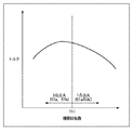
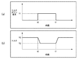
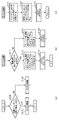
図4は、排気温度と点火タイミングとの関係及びトルクと点火タイミングとの関係を示す図である。また、図5において、(a)はトルクダウン要求と時間との関係を示す図であり、(b)はトルクと時間との関係を示す図である。また、図6において、(a)はエンジン制御部100の全体的な制御手順を示す図であり、(b)は第1点火制御の詳細な制御手順を示す図であり、(c)は第2点火制御の詳細な制御手順を示す図である。
FIG. 4 is a diagram illustrating the relationship between the exhaust temperature and the ignition timing and the relationship between the torque and the ignition timing. 5A is a diagram showing the relationship between the torque down request and time, and FIG. 5B is a diagram showing the relationship between torque and time. 6A is a diagram illustrating an overall control procedure of the
まず、ステップS100では、判定部が車両のドライバの操作に起因しない予め定めた自動トルクダウン条件が成立したか否かを判定する。車両のドライバの操作に起因しない自動トルクダウン条件としては、例えば、発進・加速時のタイヤの空転を防止するトラクションコントロールシステム77(TCS)によるトルクダウンや自動変速機のギアチェンジの際に行われるトルクダウン等が挙げられる。図5(a)で示すように、トルクダウン要求量T1がスカラ量としてエンジン制御部100に入力され、判定部によって判定が行われることとなる。
First, in step S100, the determination unit determines whether or not a predetermined automatic torque down condition that does not result from the operation of the driver of the vehicle is satisfied. The automatic torque down condition not caused by the operation of the driver of the vehicle is performed, for example, at the time of torque reduction by the traction control system 77 (TCS) for preventing tire slipping at the time of start / acceleration or gear change of the automatic transmission. Torque down etc. are mentioned. As shown in FIG. 5A, the torque reduction request amount T1 is input to the
ステップS110で自動トルクダウン条件が成立したと判定した場合には、少なくとも点火プラグ51aにより燃焼室17内の混合気を点火する第1点火制御を行う。一方、ステップS110で自動トルクダウン条件が成立していないと判定した場合には、点火プラグ51bのみにより混合気を点火する第2点火制御を行う。第1又は第2点火制御のいずれかを行った後に一連の処理を終了する。
If it is determined in step S110 that the automatic torque-down condition is satisfied, the first ignition control for igniting the air-fuel mixture in the
次に、図6(b)を用いて、第1点火制御の処理手順について説明する。まず、ステップS111において、判定部が、機関回転数が閾値Th1以下である(図3で示す低回転数領域である)か否かを判定する。 Next, the processing procedure of the first ignition control will be described with reference to FIG. First, in step S111, the determination unit determines whether or not the engine speed is equal to or less than a threshold value Th1 (the low speed range shown in FIG. 3).
ステップS111で機関回転数が閾値Th1以下である(低回転数領域である)と判定した場合には、点火プラグ51a、51bについての、エンジン回転速度、吸入空気量に応じた点火タイミングを決定する。その後、ステップS112において、ステップS111で決定された点火タイミングに、点火プラグ51a、51bの双方を用いて燃焼室内の混合気に点火して一連の処理を終了する。
When it is determined in step S111 that the engine speed is equal to or less than the threshold value Th1 (a low speed range), ignition timings corresponding to the engine speed and the intake air amount for the
一方、ステップS111で機関回転数が閾値Th1よりも大きい(高回転数領域である)と判定した場合には、ステップS114で点火プラグ51aについての、エンジン回転速度、吸入空気量に応じた点火タイミングを決定する。その後、ステップS115において、点火プラグ51aを用いて燃焼室内の混合気に点火して一連の処理を終了する。
On the other hand, if it is determined in step S111 that the engine speed is larger than the threshold value Th1 (a high speed range), the ignition timing corresponding to the engine speed and the intake air amount for the
このように、エンジン制御部100は、ドライバの操作に起因しない自動トルクダウン条件が成立した場合には、トルクダウンを行う必要がないため、点火リタードを行わない。このため、排気温度が触媒コンバータの適正温度範囲を超えることがなく、点火プラグ51a、51bのうち少なくとも点火プラグ51aを用いて燃焼室内の混合気に点火すればよいこととなる。
As described above, the
次に、図6(c)を用いて、第2点火制御の処理手順について説明する。まず、ステップS121でトルクダウン要求量に応じた目標トルクを図5(b)で示すように算出する。すなわち、目標トルクT2は、トルクT0及びトルクダウン要求量T1に基づいて、T2=T0−T1で算出することができる。 Next, the process procedure of 2nd ignition control is demonstrated using FIG.6 (c). First, in step S121, a target torque corresponding to the torque reduction request amount is calculated as shown in FIG. That is, the target torque T2 can be calculated as T2 = T0−T1 based on the torque T0 and the torque down request amount T1.
そして、ステップS122において、ステップS121で算出された目標トルクT2に応じた点火プラグ51bの点火タイミングを決定する。ここで決定される点火プラグ51bの点火タイミングは、第1点火制御で点火プラグ51aのみにより混合気を点火する場合(ステップS115)に比べて点火タイミングを遅角させる。更に、ここで決定される点火プラグ51bの点火タイミングは、第1点火制御で点火プラグ51a、51bにより混合気を点火する場合(ステップS113)の点火プラグ51a、51bの双方の点火タイミングよりも遅角させる。その後、ステップS123において、ステップS122で決定された点火タイミングに、点火プラグ51bのみにより混合気を点火し、一連の処理を終了する。
In step S122, the ignition timing of the
このように、点火プラグの点火タイミングを遅角させることによりトルクダウン(すなわち、点火リタード)を行うと、図4で示すように、遅角側にした分だけ排気温度が高まってしまう。しかし、第2点火制御では、燃焼室の側壁に近接する点火プラグ51bのみを用いて点火するため、混合気が燃焼室の側壁で冷却されて冷却損が生じることにより、排気温度の上昇を抑制することができる。
Thus, if torque reduction (that is, ignition retard) is performed by retarding the ignition timing of the spark plug, as shown in FIG. However, in the second ignition control, ignition is performed using only the
以上述べた通り、本実施形態によれば、点火リタード量を低減しながら所望のトルクダウンを行うことにより、排気温度の上昇を抑制して排気中に含まれる有害物質の除去効率の低下を抑制することができる。 As described above, according to the present embodiment, a desired torque reduction is performed while reducing the ignition retard amount, thereby suppressing a rise in exhaust temperature and a reduction in the removal efficiency of harmful substances contained in the exhaust. can do.
なお、本実施形態では、エンジン制御部100が判定部及び点火制御部を有する構成としたが、これらがエンジン制御部100とは独立して設けられていてもよい。例えば、上述の点火システム52がこれらを有するものとしてもよい。
In the present embodiment, the
1 エンジン本体(車両用エンジン)
11 シリンダ(気筒)
17 燃焼室
51a 点火プラグ(第1点火プラグ)
51b 点火プラグ(第2点火プラグ)
100 エンジン制御部(点火制御手段)
CL シリンダ11の中心線
1 Engine body (vehicle engine)
11 cylinders
17
51b Spark plug (second spark plug)
100 Engine control unit (ignition control means)
Claims (5)
車両のドライバの操作に起因しない予め定めた自動トルクダウン条件が成立したか否かを判定する判定手段と、
前記判定手段が前記自動トルクダウン条件が成立していないと判定した場合は、少なくとも前記第1点火プラグにより燃焼室内の混合気を点火する第1点火制御を行い、前記判定手段が前記自動トルクダウン条件が成立したと判定した場合は前記第2点火プラグのみにより前記混合気を点火する第2点火制御を行う点火制御手段と、
を備えたことを特徴とする制御装置。 A first spark plug in which an ignition point is set on a substantially center line of the cylinder, and a second spark plug in which the ignition point is set at a position away from the ignition point of the first spark plug are provided for each cylinder. In a vehicle engine control device,
Determining means for determining whether or not a predetermined automatic torque down condition not caused by an operation of a driver of the vehicle is satisfied;
If the determination means determines that the automatic torque down condition is not satisfied, at least first ignition control is performed to ignite the air-fuel mixture in the combustion chamber by the first spark plug, and the determination means performs the automatic torque reduction. Ignition control means for performing second ignition control for igniting the air-fuel mixture only with the second spark plug when it is determined that the condition is satisfied;
A control device comprising:
前記第1点火制御においては前記第1点火プラグのみにより前記混合気を点火し、かつ、前記第2点火制御においては、前記第1点火制御よりも、点火タイミングを遅角させることを特徴とする請求項1に記載の制御装置。 The ignition control means includes
In the first ignition control, the air-fuel mixture is ignited only by the first ignition plug, and in the second ignition control, the ignition timing is retarded as compared with the first ignition control. The control device according to claim 1.
前記第1点火制御においては前記第1及び第2点火プラグにより前記混合気を点火し、かつ、前記第2点火制御においては、前記第1点火制御における前記第1及び第2点火プラグの双方の点火タイミングよりも、点火タイミングを遅角させることを特徴とする請求項1に記載の制御装置。 The ignition control means includes
In the first ignition control, the air-fuel mixture is ignited by the first and second spark plugs, and in the second ignition control, both of the first and second spark plugs in the first ignition control are used. The control device according to claim 1, wherein the ignition timing is retarded from the ignition timing.
車両のドライバの操作に起因しない予め定めた自動トルクダウン条件が成立したか否かを判定する判定工程と、
前記判定工程が前記自動トルクダウン条件が成立していないと判定した場合は、少なくとも前記第1点火プラグにより燃焼室内の混合気を点火する第1点火制御を行い、前記判定工程が前記自動トルクダウン条件が成立したと判定した場合は前記第2点火プラグのみにより前記混合気を点火する第2点火制御を行う点火制御工程と、
を有することを特徴とする制御方法。 A first spark plug in which an ignition point is set on a substantially center line of the cylinder and a second spark plug in which the ignition point is set at a position away from the ignition point of the first spark plug are provided for each cylinder. In a method for controlling a vehicle engine,
A determination step of determining whether or not a predetermined automatic torque-down condition not caused by an operation of the driver of the vehicle is satisfied;
If the determination step determines that the automatic torque-down condition is not satisfied, at least a first ignition control is performed to ignite the air-fuel mixture in the combustion chamber by the first spark plug, and the determination step includes the automatic torque-down condition. An ignition control step of performing a second ignition control for igniting the air-fuel mixture only by the second spark plug when it is determined that the condition is satisfied;
A control method characterized by comprising:
Priority Applications (1)
| Application Number | Priority Date | Filing Date | Title |
|---|---|---|---|
| JP2008165062A JP5412755B2 (en) | 2008-06-24 | 2008-06-24 | Control device and control method for vehicle engine |
Applications Claiming Priority (1)
| Application Number | Priority Date | Filing Date | Title |
|---|---|---|---|
| JP2008165062A JP5412755B2 (en) | 2008-06-24 | 2008-06-24 | Control device and control method for vehicle engine |
Publications (2)
| Publication Number | Publication Date |
|---|---|
| JP2010007499A true JP2010007499A (en) | 2010-01-14 |
| JP5412755B2 JP5412755B2 (en) | 2014-02-12 |
Family
ID=41588286
Family Applications (1)
| Application Number | Title | Priority Date | Filing Date |
|---|---|---|---|
| JP2008165062A Expired - Fee Related JP5412755B2 (en) | 2008-06-24 | 2008-06-24 | Control device and control method for vehicle engine |
Country Status (1)
| Country | Link |
|---|---|
| JP (1) | JP5412755B2 (en) |
Citations (4)
| Publication number | Priority date | Publication date | Assignee | Title |
|---|---|---|---|---|
| JPH03286186A (en) * | 1990-03-30 | 1991-12-17 | Mazda Motor Corp | Ignition device for engine |
| JPH05141336A (en) * | 1991-11-22 | 1993-06-08 | Honda Motor Co Ltd | Ignition device for internal combustion engine |
| JPH06280730A (en) * | 1993-03-26 | 1994-10-04 | Mazda Motor Corp | Ignition device for engine |
| JPH112172A (en) * | 1997-06-12 | 1999-01-06 | Nissan Motor Co Ltd | Control device for internal combustion engine |
-
2008
- 2008-06-24 JP JP2008165062A patent/JP5412755B2/en not_active Expired - Fee Related
Patent Citations (4)
| Publication number | Priority date | Publication date | Assignee | Title |
|---|---|---|---|---|
| JPH03286186A (en) * | 1990-03-30 | 1991-12-17 | Mazda Motor Corp | Ignition device for engine |
| JPH05141336A (en) * | 1991-11-22 | 1993-06-08 | Honda Motor Co Ltd | Ignition device for internal combustion engine |
| JPH06280730A (en) * | 1993-03-26 | 1994-10-04 | Mazda Motor Corp | Ignition device for engine |
| JPH112172A (en) * | 1997-06-12 | 1999-01-06 | Nissan Motor Co Ltd | Control device for internal combustion engine |
Also Published As
| Publication number | Publication date |
|---|---|
| JP5412755B2 (en) | 2014-02-12 |
Similar Documents
| Publication | Publication Date | Title |
|---|---|---|
| JP5168233B2 (en) | Engine fuel injection control device | |
| JP4952732B2 (en) | Internal combustion engine control method and internal combustion engine control system | |
| US8528323B2 (en) | System and method for particulate matter filter regeneration using a catalytic converter as a combustor | |
| US10465614B2 (en) | Vehicle control device | |
| JP4385940B2 (en) | INTERNAL COMBUSTION ENGINE DEVICE, AUTOMOBILE MOUNTING THE SAME AND METHOD FOR STOPping OPERATION OF INTERNAL COMBUSTION ENGINE | |
| JP2006322371A (en) | Engine control device, vehicle control device and engine control method | |
| CN104395587A (en) | Control device for internal combustion engine | |
| EP3342659B1 (en) | Vehicle control device | |
| JP5515972B2 (en) | Exhaust system for multi-cylinder engine | |
| JP5050941B2 (en) | Engine air-fuel ratio control | |
| WO2018168693A1 (en) | Vehicle control device | |
| JP3771101B2 (en) | Control device for internal combustion engine | |
| JP5412755B2 (en) | Control device and control method for vehicle engine | |
| JP5104453B2 (en) | Internal combustion engine control method and internal combustion engine system | |
| EP1936160B1 (en) | Exhaust gas treatment device regeneration inhibiting fuel combustion in an engine cylinder | |
| JP6156224B2 (en) | Engine control device | |
| JP4985465B2 (en) | Internal combustion engine control method and internal combustion engine control system | |
| JP2010084619A (en) | Control device of engine | |
| JP4182725B2 (en) | Engine control device | |
| JP3632325B2 (en) | Engine torque control device | |
| JP4910961B2 (en) | INTERNAL COMBUSTION ENGINE DEVICE, VEHICLE MOUNTING THE SAME, AND METHOD FOR CONTROLLING INTERNAL COMBUSTION ENGINE DEVICE | |
| JP5151875B2 (en) | Control method and control device for spark ignition engine | |
| JPH09242573A (en) | Control device for automatic transmission | |
| WO2021111163A1 (en) | Catalyst warm-up operation control method for internal combustion engine, and catalyst warm-up operation control device | |
| JP4483776B2 (en) | Ignition timing control device for internal combustion engine |
Legal Events
| Date | Code | Title | Description |
|---|---|---|---|
| RD03 | Notification of appointment of power of attorney |
Free format text: JAPANESE INTERMEDIATE CODE: A7423 Effective date: 20101001 |
|
| RD04 | Notification of resignation of power of attorney |
Free format text: JAPANESE INTERMEDIATE CODE: A7424 Effective date: 20101001 |
|
| A621 | Written request for application examination |
Free format text: JAPANESE INTERMEDIATE CODE: A621 Effective date: 20110523 |
|
| RD02 | Notification of acceptance of power of attorney |
Free format text: JAPANESE INTERMEDIATE CODE: A7422 Effective date: 20120229 |
|
| A521 | Written amendment |
Free format text: JAPANESE INTERMEDIATE CODE: A523 Effective date: 20120329 |
|
| A131 | Notification of reasons for refusal |
Free format text: JAPANESE INTERMEDIATE CODE: A131 Effective date: 20120918 |
|
| A521 | Written amendment |
Free format text: JAPANESE INTERMEDIATE CODE: A523 Effective date: 20121114 |
|
| A131 | Notification of reasons for refusal |
Free format text: JAPANESE INTERMEDIATE CODE: A131 Effective date: 20130326 |
|
| A521 | Written amendment |
Free format text: JAPANESE INTERMEDIATE CODE: A523 Effective date: 20130523 |
|
| TRDD | Decision of grant or rejection written | ||
| A01 | Written decision to grant a patent or to grant a registration (utility model) |
Free format text: JAPANESE INTERMEDIATE CODE: A01 Effective date: 20131015 |
|
| A61 | First payment of annual fees (during grant procedure) |
Free format text: JAPANESE INTERMEDIATE CODE: A61 Effective date: 20131028 |
|
| R150 | Certificate of patent or registration of utility model |
Ref document number: 5412755 Country of ref document: JP Free format text: JAPANESE INTERMEDIATE CODE: R150 |
|
| LAPS | Cancellation because of no payment of annual fees |