JP2010007402A - Fish tail of tunnel excavator, fish tail protection device, bit exchanger, and bit exchanging method - Google Patents
Fish tail of tunnel excavator, fish tail protection device, bit exchanger, and bit exchanging method Download PDFInfo
- Publication number
- JP2010007402A JP2010007402A JP2008169843A JP2008169843A JP2010007402A JP 2010007402 A JP2010007402 A JP 2010007402A JP 2008169843 A JP2008169843 A JP 2008169843A JP 2008169843 A JP2008169843 A JP 2008169843A JP 2010007402 A JP2010007402 A JP 2010007402A
- Authority
- JP
- Japan
- Prior art keywords
- bit
- cutter head
- fishtail
- actuator
- support cylinder
- Prior art date
- Legal status (The legal status is an assumption and is not a legal conclusion. Google has not performed a legal analysis and makes no representation as to the accuracy of the status listed.)
- Granted
Links
- 238000000034 method Methods 0.000 title claims description 23
- 241000251468 Actinopterygii Species 0.000 title abstract description 28
- 125000006850 spacer group Chemical group 0.000 claims description 53
- 239000004576 sand Substances 0.000 claims description 10
- 238000001125 extrusion Methods 0.000 claims description 6
- 230000002093 peripheral effect Effects 0.000 claims description 6
- 230000008602 contraction Effects 0.000 claims description 2
- 238000009412 basement excavation Methods 0.000 abstract description 25
- 239000002689 soil Substances 0.000 abstract description 2
- 230000001681 protective effect Effects 0.000 abstract 2
- 235000015277 pork Nutrition 0.000 description 23
- XLYOFNOQVPJJNP-UHFFFAOYSA-N water Substances O XLYOFNOQVPJJNP-UHFFFAOYSA-N 0.000 description 5
- 238000010586 diagram Methods 0.000 description 2
- 230000000149 penetrating effect Effects 0.000 description 2
- 238000013019 agitation Methods 0.000 description 1
- 210000003298 dental enamel Anatomy 0.000 description 1
- 230000000694 effects Effects 0.000 description 1
- 230000007774 longterm Effects 0.000 description 1
- 238000003756 stirring Methods 0.000 description 1
Images


Abstract
Description
本発明は、長距離掘削においてフィッシュテールを良好な状態で機能させられるトンネル掘削機のフィッシュテール、フィッシュテール保護装置、ビット交換装置及びビット交換方法に関する。 The present invention relates to a fish tail, a fish tail protection device, a bit exchange device, and a bit exchange method of a tunnel excavator that can function a fish tail in a good state in long-distance excavation.
一般的なトンネル掘削機は、円筒形状をなす掘削機本体の前部にカッタヘッドが駆動回転可能に装着され、このカッタヘッドにディスクカッタやカッタビットなどのカッタ類が多数取り付けられる一方、掘削機本体の後部には当該掘削機本体を前進させる多数の推進ジャッキが装着されると共にトンネルの内壁面にセグメントを組み付けるエレクタ装置が装着される。 In general tunnel excavators, a cutter head is mounted on a front portion of a cylindrical excavator main body so as to be able to drive and rotate. On the other hand, many cutters such as disc cutters and cutter bits are attached to the cutter head. A large number of propulsion jacks for advancing the excavator main body are attached to the rear part of the main body, and an erector device for assembling the segments to the inner wall surface of the tunnel is attached.
従って、カッタヘッドを回転しながら推進ジャッキを伸長させることで、既設セグメントから掘削反力を得て掘削機本体が前進すると共にカッタヘッドが前方の地盤を掘削し、トンネルが築造される。 Therefore, by extending the propulsion jack while rotating the cutter head, the excavator body moves forward by obtaining the excavation reaction force from the existing segment, and the cutter head excavates the ground in front, thereby constructing the tunnel.
近年、トンネルは長距離化の傾向にあり、このため、トンネル掘削の作業中にカッタヘッドに装着されたディスクカッタやカッタビットなどが摩耗してしまう。これらのカッタ類が摩耗すると地盤の掘削効率が低下するので、掘削作業を停止して摩耗したカッタ類を交換しなければならない。 In recent years, tunnels tend to be long distances. For this reason, disk cutters and cutter bits attached to the cutter head wear during tunnel excavation work. When these cutters are worn, the excavation efficiency of the ground is lowered. Therefore, excavation work must be stopped and the worn cutters must be replaced.
ところが、このカッタ類の交換作業にあたっては、切羽とバルクヘッドとの間のチャンバを含む空間内の泥水や掘削土砂を外部に排出した後この空間内に空気を供給して圧気する(他の方法として薬注や凍結による地盤改良等がある)ことで、切羽の崩落を抑制し、この状態下で作業者が圧気空間内に入ってカッタ類の交換作業を行っていた。 However, when exchanging the cutters, the muddy water and excavated soil in the space including the chamber between the face and the bulkhead are discharged to the outside, and then air is supplied into the space to compress the air (other methods) In this situation, the collapsing of the face was suppressed, and the worker entered the pressured air space to replace the cutters.
そのため、カッタ交換作業に長時間を要してしまい、また、作業者の安全性を十分考慮しなければならず、特に、ディスクカッタは重量物であるために交換時の搬送作業は困難を極め、交換作業の作業効率が良くなかった。 Therefore, it takes a long time to replace the cutter, and the safety of the operator must be fully considered. In particular, since the disc cutter is heavy, it is extremely difficult to carry it out during replacement. The work efficiency of the replacement work was not good.
そこで、作業者が切羽側やチャンバに出ることなく、機内から摩耗したディスクカッタやカッタビットを新しいものと交換可能としたものが、例えば、特許文献1に記載されている。 Therefore, for example, Patent Document 1 discloses a technique in which a disc cutter or cutter bit worn from the inside of the machine can be replaced with a new one without leaving the face or chamber.
この特許文献1に記載されたトンネル掘削機は、カッタヘッドの中央部の支持筒をカッタ交換室として利用すると共に、この支持筒に回転筒を設けて複数本のカッタスポークと連通及び遮断可能とすることで、複数本のカッタスポークに装着された全てのカッタ類を容易に交換可能としたものであり、土圧式・泥土圧式・泥水式シールド掘削機やトンネルボーリングマシンなどのトンネル掘削機に適用することができる。 The tunnel excavator described in Patent Document 1 uses a support cylinder at the center of the cutter head as a cutter exchange chamber, and is provided with a rotating cylinder in the support cylinder so that it can communicate with and shut off a plurality of cutter spokes. This makes it possible to easily replace all the cutters mounted on multiple Katspoke, and is applicable to tunnel excavators such as earth pressure type, mud pressure type, mud type shield excavators and tunnel boring machines. can do.
本発明は、上述した特許文献1に記載されたトンネル掘削機に着目して提案されたもので、泥水式シールド掘削機等のカッタヘッドに装備されるフィッシュテールを長距離掘削下においても良好な状態で機能させられるようにしたものである。 The present invention has been proposed by paying attention to the tunnel excavator described in Patent Document 1 described above, and the fishtail provided in the cutter head of a muddy water type shield excavator is excellent even under long-distance excavation. It is made to function in the state.
即ち、泥水式シールド掘削機等のカッタヘッドには、先行掘削と攪拌を目的として面盤中央部に大型の3角翼の形状をしたフィッシュテール(ビット)が装備されることは良く知られている。 That is, it is well known that a cutter head of a muddy water type shield excavator is equipped with a fishtail (bit) having a large triangular blade shape in the center of the face plate for the purpose of advanced excavation and agitation. Yes.
ところが、このフィッシュテールは、当該フィッシュテールで掘削した土砂を当該フィッシュテールの両側端部を経てカッタヘッドの開口より当該カッタヘッドの裏面側に画成されたチャンバに取り込むようになっているので、フィッシュテールの両側端部の摩耗が中央部(本体部)に比べて著しく激しく、長距離掘削下においてはフィッシュテールの機能が十分に発揮されなくなるという問題点があった。 However, this fish tail is designed to take in the earth and sand excavated by the fish tail into the chamber defined on the back side of the cutter head from the opening of the cutter head through both ends of the fish tail. There is a problem that the wear of both ends of the fishtail is extremely severe compared to the central portion (main body portion), and the function of the fishtail is not fully exhibited under long-distance excavation.
そこで、本発明の目的は、カッタヘッドに装備されるフィッシュテールを長距離掘削下においても良好な状態で機能させて施工性を向上させることができるトンネル掘削機のフィッシュテール、フィッシュテール保護装置、ビット交換装置及びビット交換方法を提供することにある。 Accordingly, an object of the present invention is to provide a fish tail for a tunnel excavator that can function in a good state even under long-distance excavation to improve workability, a fish tail protection device, A bit exchange apparatus and a bit exchange method are provided.
上述の目的を達成するための本発明に係るトンネル掘削機のフィッシュテールは、
掘削機本体の前部に駆動回転自在に装着されたカッタヘッドの中央部にフィッシュテールを設け、該フィッシュテールで掘削した土砂を当該フィッシュテールの両側端部を経てカッタヘッドの開口より当該カッタヘッドの裏面側に画成されたチャンバに取り込むようにしたトンネル掘削機において、
前記フィッシュテールの両側端部を本体部と別体に形成し、該両側端部を前記カッタヘッドに対し掘進方向に出没させて交換可能に設けたことを特徴とする。
The fishtail of the tunnel excavator according to the present invention for achieving the above-described object is
A fishtail is provided at the center of the cutter head that is rotatably mounted on the front of the excavator body, and the earth and sand excavated by the fishtail passes through both ends of the fishtail and is opened from the cutter head through the cutter head. In the tunnel excavator adapted to be taken into the chamber defined on the back side of
The fishtail is characterized in that both end portions of the fishtail are formed separately from the main body portion, and the both end portions are provided so as to be exchanged by being protruded and retracted in the excavation direction with respect to the cutter head.
上述の目的を達成するための本発明に係るトンネル掘削機のフィッシュテール保護装置は、
掘削機本体の前部に駆動回転自在に装着されたカッタヘッドの中央部にフィッシュテールを設け、該フィッシュテールで掘削した土砂を当該フィッシュテールの両側端部を経てカッタヘッドの開口より当該カッタヘッドの裏面側に画成されたチャンバに取り込むようにしたトンネル掘削機において、
前記フィッシュテールの両側端部と同じ半径位置のカッタヘッドにフィッシュテール保護ビットを設け、該フィッシュテール保護ビットを前記カッタヘッドに対し掘進方向に出没させて交換可能に設けたことを特徴とする。
In order to achieve the above object, a fishtail protection device for a tunnel excavator according to the present invention comprises:
A fishtail is provided at the center of the cutter head that is rotatably mounted on the front of the excavator body, and the earth and sand excavated by the fishtail passes through both ends of the fishtail and is opened from the cutter head through the cutter head. In the tunnel excavator adapted to be taken into the chamber defined on the back side of
A fishtail protection bit is provided on a cutter head at the same radial position as both side ends of the fishtail, and the fishtail protection bit is provided so as to be replaceable by protruding and retracting in the digging direction with respect to the cutter head.
上述の目的を達成するための本発明に係るトンネル掘削機のビット交換装置は、
前記フィッシュテールの両側端部と前記フィッシュテール保護ビットを総称する交換式ビットを交換するためのビット交換装置を備えたトンネル掘削機において、
前記ビット交換装置は、
前記カッタヘッドの前面部に貫設されて前記交換式ビットと該交換式ビットの後面部に連接される一以上のスペーサをカッタヘッドの内部から出入り可能に支持し得る前,後両端面開放の支持筒体と、
前記支持筒体の軸心と直交する方向に動作してカッタヘッドの内部から前記支持筒体を開閉可能なゲートと、
前記カッタヘッドの後面部に貫設されて前記交換式ビット又はスペーサの後面部に対し接続又は分離可能なビット押引き用のアクチュエータと、
を備えたことを特徴とする。
また、前記交換式ビットの支持筒体からの抜出時と支持筒体への挿入時にのみ支持筒体の後端面側に連結される半割りのシールリングを、更に備えたことを特徴とする。
また、前記交換式ビットとスペーサとアクチュエータとは、互いに連結される際には回り止め手段により回り止めされることを特徴とする。
また、前記支持筒体は、カッタヘッドの内部に位置して、交換式ビット又はスペーサの外周部に係合して軸方向移動を阻止する固定手段を有することを特徴とする。
In order to achieve the above object, a bit exchanging device for a tunnel excavator according to the present invention comprises:
In a tunnel excavator provided with a bit exchanging device for exchanging interchangeable bits generically referring to both ends of the fishtail and the fishtail protection bit,
The bit exchange device is:
The front and rear end surfaces of the cutter head are opened before and after the exchangeable bit and one or more spacers connected to the rear surface of the exchangeable bit can be supported to be able to enter and exit from the inside of the cutter head. A support cylinder;
A gate that operates in a direction orthogonal to the axis of the support cylinder to open and close the support cylinder from the inside of the cutter head;
An actuator for pushing and pulling the bit, which is provided in the rear surface of the cutter head and can be connected to or separated from the rear surface of the replaceable bit or spacer;
It is provided with.
Further, the present invention is further characterized by further comprising a half-seal ring that is connected to the rear end face side of the support cylinder only when the replaceable bit is extracted from the support cylinder and inserted into the support cylinder. .
The interchangeable bit, the spacer, and the actuator are prevented from rotating by a rotation preventing means when they are connected to each other.
In addition, the support cylinder has a fixing means that is located inside the cutter head and engages with the outer peripheral portion of the replaceable bit or spacer to prevent axial movement.
上述の目的を達成するための本発明に係るトンネル掘削機のビット交換方法は、
前記ビット交換装置を用いて交換式ビットを交換するビット交換方法であって、
摩耗した交換式ビットと一以上のスペーサとアクチュエータとが互いに連結された状態からアクチュエータを収縮させて摩耗した交換式ビット及びスペーサのカッタヘッド内への引込みを開始する第1の工程と、
アクチュエータを分離・収縮させてカッタヘッド内に引き込まれたスペーサを取り外す第2の工程と、
アクチュエータを伸長・接続させた後収縮させて摩耗した交換式ビットをカッタヘッド内に引き込む第3の工程と、
アクチュエータを分離させて摩耗した交換式ビットを取り外す前にゲートを閉めて支持筒体を閉塞する第4の工程と、
アクチュエータを分離させて摩耗した交換式ビットを取り外した後、新しい交換式ビットをアクチュエータに接続して取り付ける第5の工程と、
ゲートを開けて支持筒体を開放し、その後アクチュエータを伸長させて新しい交換式ビットの押出しを開始する第6の工程と、
新しい交換式ビットがカッタヘッド外に押し出された後、アクチュエータを分離・収縮させて新しい交換式ビットにスペーサを連結する第7の工程と、
スペーサにアクチュエータを伸長・接続させた後さらに伸長させて新しい交換式ビット及びスペーサの押出しを再開し、新しい交換式ビットをカッタヘッド外の所定位置まで押し出す第8の工程と、
を有することを特徴とする。
また、前記スペーサを複数用いる際は、前記第1の工程及び第2の工程においてスペーサのカッタヘッド内への引込み・取外し動作が複数回繰り返されると共に、前記第7の工程及び第8の工程においてスペーサの連結・押出し動作が複数回繰り返されることを特徴とする。
また、前記第3の工程において摩耗した交換式ビットをカッタヘッド内に引き込んだ後第4の工程においてゲートを閉めて支持筒体を閉塞するまでの間と、前記第5の工程において新しい交換式ビットを取り付けた後第6の工程においてゲートを開けて支持筒体を開放するまでの間は、支持筒体の後端面側に半割りのシールリングが連結されることを特徴とする。
また、前記交換式ビットとスペーサとアクチュエータとは、互いに連結状態にある時は回り止めされることを特徴とする。
また、前記アクチュエータを分離・収縮させる際は、交換式ビット及び/又はスペーサの軸方向移動が阻止されることを特徴とする。
In order to achieve the above-mentioned object, a bit exchanging method for a tunnel excavator according to the present invention includes:
A bit exchange method for exchanging exchangeable bits using the bit exchange device,
A first step of retracting the worn replaceable bit and the spacer into the cutter head by contracting the actuator from a state in which the worn replaceable bit, the one or more spacers and the actuator are coupled to each other;
A second step of separating and contracting the actuator to remove the spacer drawn into the cutter head;
A third step of drawing the exchangeable bit worn by contraction after extending and connecting the actuator into the cutter head;
A fourth step of closing the gate and closing the support cylinder before removing the wearable replaceable bit by separating the actuator;
A fifth step of separating and attaching the worn replaceable bit after separating the actuator and then attaching and attaching a new replaceable bit to the actuator;
A sixth step of opening the gate to release the support cylinder, and then extending the actuator to begin extruding a new replaceable bit;
After the new replaceable bit is pushed out of the cutter head, the actuator is separated and contracted to connect the spacer to the new replaceable bit;
An eighth step in which the actuator is extended and connected to the spacer and then further extended to resume extrusion of the new replaceable bit and the spacer and push the new replaceable bit to a predetermined position outside the cutter head;
It is characterized by having.
Further, when a plurality of the spacers are used, in the first step and the second step, the drawing / removing operation of the spacers into the cutter head is repeated a plurality of times, and in the seventh step and the eighth step. The spacer connecting / extruding operation is repeated a plurality of times.
Further, after the replaceable bit worn in the third step is drawn into the cutter head, the gate is closed in the fourth step and the support cylinder is closed, and the new replaceable bit in the fifth step. After the bit is attached, the half seal ring is connected to the rear end face side of the support cylinder until the gate is opened and the support cylinder is opened in the sixth step.
The exchangeable bit, the spacer, and the actuator are prevented from rotating when they are connected to each other.
Further, when the actuator is separated and contracted, the axial movement of the replaceable bit and / or the spacer is prevented.
本発明に係るトンネル掘削機のフィッシュテールによれば、摩耗した両側端部を本体部と分離させてカッタヘッド内に引き込むことで、当該引込み位置に近接するカッタヘッド中央部の支持筒内をビット交換室とする等して、容易かつ安全に新しい両側端部と交換することができ、フィッシュテールを長距離掘削下においても良好な状態で機能させられる。 According to the fishtail of the tunnel excavator according to the present invention, the worn side end portions are separated from the main body portion and pulled into the cutter head, so that the bit inside the support cylinder at the center portion of the cutter head close to the retracted position. It can be easily and safely exchanged with new end portions, for example, as an exchange chamber, and the fishtail can function in a good state even under long-distance excavation.
本発明に係るトンネル掘削機のフィッシュテール保護装置によれば、フィッシュテール保護ビットの介在でフィッシュテールの両側端部の摩耗を低減することができる一方、摩耗したフィッシュテール保護ビットをカッタヘッド内に引き込むことで、当該引込み位置に近接するカッタヘッド中央部の支持筒内をビット交換室とする等して、容易かつ安全に新しいフィッシュテール保護ビットと交換することができ、フィッシュテールを長距離掘削下においても良好な状態で機能させられる。 According to the fishtail protection device for a tunnel excavator according to the present invention, it is possible to reduce wear on both side ends of the fishtail by interposing the fishtail protection bit, while the worn fishtail protection bit is placed in the cutter head. By pulling in, the inside of the support cylinder in the center of the cutter head close to the retracting position can be replaced with a new fishtail protection bit, for example, by exchanging the fishtail for a long distance. Even under, it can function in a good condition.
本発明に係るトンネル掘削機のビット交換装置によれば、ゲートによりカッタヘッド内への土砂の侵入を確実に防止して交換式ビット及びスペーサをアクチュエータによりカッタヘッドに対し円滑に出入りさせることができ、当該出入り位置に近接するカッタヘッド中央部の支持筒内をビット交換室とする等して、容易かつ安全にビット交換が行え、延いてはフィッシュテールを長距離掘削下においても良好な状態で機能させられる。 According to the bit exchanging device of the tunnel excavator according to the present invention, it is possible to reliably prevent the earth and sand from entering the cutter head by the gate, and to allow the exchangeable bit and the spacer to smoothly enter and exit the cutter head by the actuator. The bit can be exchanged easily and safely by making the inside of the support cylinder in the center of the cutter head close to the entry / exit position a bit exchange chamber, and the fish tail is in good condition even under long-distance excavation. Made to work.
本発明に係るトンネル掘削機のビット交換方法によれば、ゲートによりカッタヘッド内への土砂の侵入を確実に防止して交換式ビット及びスペーサをアクチュエータによりカッタヘッドに対し円滑に出入りさせることができ、当該出入り位置に近接するカッタヘッド中央部の支持筒内をビット交換室とする等して、容易かつ安全にビット交換が行え、延いてはフィッシュテールを長距離掘削下においても良好な状態で機能させられる。 According to the bit exchanging method of the tunnel excavator according to the present invention, it is possible to reliably prevent the earth and sand from entering the cutter head by the gate, and to allow the exchangeable bit and the spacer to smoothly enter and exit the cutter head by the actuator. The bit can be exchanged easily and safely by making the inside of the support cylinder in the center of the cutter head close to the entry / exit position a bit exchange chamber, and the fish tail is in good condition even under long-distance excavation. Made to work.
以下、本発明に係るトンネル掘削機のフィッシュテール、フィッシュテール保護装置、ビット交換装置及びビット交換方法を実施例により図面を用いて詳細に説明する。 Hereinafter, a fishtail, a fishtail protection device, a bit exchange device, and a bit exchange method of a tunnel excavator according to the present invention will be described in detail with reference to the drawings.
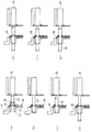
図1は本発明の実施例1を示す泥水式シールド掘削機の側断面図、図2は同じく正面図、図3は図1のA部詳細図、図4はビット交換(引込み)手順を示す工程図、図5はビット交換(押出し)手順を示す工程図である。 1 is a side sectional view of a muddy water type shield excavator showing Embodiment 1 of the present invention, FIG. 2 is a front view of the same, FIG. 3 is a detailed view of part A of FIG. 1, and FIG. FIG. 5 is a process diagram showing a bit exchange (extrusion) procedure.
図1及び図2に示すように、円筒形状をなす掘削機本体10の前部にはカッタヘッド11が回転自在に支持されている。即ち、掘削機本体10の前部にはカッタヘッド11の後方に位置してバルクヘッド12が取り付けられ、このバルクヘッド12にカッタヘッド11の中央部に設けた前,後両端面閉塞の支持筒13の後端部がリングギア付軸受14により回転自在に支持されるのである。
As shown in FIGS. 1 and 2, a
前記リングギア付軸受14のリングギア14aには、バルクヘッド12に支持された複数のカッタ旋回モータ15の駆動ギア16が噛み合っている。従って、カッタ旋回モータ15を駆動して駆動ギア16を回転させると、リングギア14aを介してカッタヘッド11を回転することができる。
The
前記カッタヘッド11とバルクヘッド12との間には掘削土砂を取り込むチャンバ17が形成されており、カッタヘッド11には後方に向けて複数の攪拌棒18が固定されている。そして、掘削機本体10内にはスクリューコンベヤ19が前傾した状態で配設され、前端部がバルクヘッド12を貫通してチャンバ17内に開口している。
A
また、掘削機本体10の後部内周面には周方向に沿って図示しないシールドジャッキ(推進ジャッキ)が複数並設されており、このシールドジャッキを後方に伸長してスプレッダを既設セグメントに押し付けることで、その反力により掘削機本体10を前進することができる。更に、掘削機本体10の後部にはトンネルの内壁面にセグメントをリング状に組み立てる図示しないエレクタ装置が設けられている。
In addition, a plurality of shield jacks (propulsion jacks) (not shown) are juxtaposed along the circumferential direction on the rear inner peripheral surface of the excavator
前記カッタヘッド11は、支持筒13の前部外周面から等間隔で放射状にそれぞれ延びた3本の第1カッタスポーク20と、これらの中間に位置して同じく支持筒13の前部外周面から等間隔で放射状にそれぞれ延びると共に外周側で面盤21と一体化された3本の第2カッタスポーク22とを有する。
The
第1カッタスポーク20の前面部には複数のディスクカッタ23とカッタビット24が取り付けられ、面盤21及び第2カッタスポーク22の前面部には複数の特殊先行ビット25や保護ビット26が取り付けられている。尚、図中27はオーバーカッタである。
A plurality of
また、カッタヘッド11の面盤中央部には、前記支持筒13の前方に位置して大型の3角翼の形状をしたメインフィッシュテール(ビット)30と、このメインフィッシュテール30の両側端部30aとは周方向に90度隔てた位置に小型のサブフィッシュテール(ビット)31がそれぞれ取り付けられる。
Further, at the center part of the face plate of the
さらに、第2カッタスポーク22の前面部には、メインフィッシュテール30の両側端部30aと同じ半径位置にフィッシュテール保護ビット(交換式ビット)32が設けられ、該フィッシュテール保護ビット32は前記第2カッタスポーク22に対し掘進(前後)方向に出没させることで交換可能になっている。
Furthermore, a fishtail protection bit (exchangeable bit) 32 is provided at the same radial position as the both
即ち、図3に示すように、フィッシュテール保護ビット32は、その後面部に連接される二つのスペーサ34と共に、前記第2カッタスポーク22の前面部に貫設された支持筒体33に、第2カッタスポーク22の内部から出入り可能に支持され、最後部のスペーサ34の後面部には、第2カッタスポーク22の後面部に貫設されたビット押引き用のジャッキ(アクチュエータ)35が分離可能に接続されている。
That is, as shown in FIG. 3, the
前記スペーサ34は、フィッシュテール保護ビット32と同じような大きさを有して二つ用いられているが、カッタヘッド11の中央部に設けた支持筒13をビット交換室としてその開口部13aから出入り可能であれば二つに限らず三以上でも又は一つでも良い。
Two
また、前記フィッシュテール保護ビット32とスペーサ34とジャッキ35とは、互いにいんろう継手のように連接され、その連接の際には、ピン(回り止め手段)40で抜け止めと回り止めがなされるようになっている。尚、回り止め手段としてスプライン嵌合でも良いが、この場合は適宜の手段で抜け止めされる必要がある。
Further, the
また、前記支持筒体33には、第2カッタスポーク22の内部に位置して、フィッシュテール保護ビット32又はスペーサ34の外周部に係合してそれらの軸方向移動を阻止するビット固定ボルト(固定手段)36が設けられる。
Further, the
そして、前記支持筒体33の後面部には、当該支持筒体33の軸心と直交する方向に動作して第2カッタスポーク22の内部から前記支持筒体33を開閉可能なゲート37が配設され、その開閉用のジャッキ38が第2カッタスポーク22内に支持されている。
A
また、前記フィッシュテール保護ビット32の支持筒体33からの抜出時と支持筒体33への挿入時にのみ、支持筒体33の後端面側に、図4及び図5で後述する半割りのシールリング39が連結されるようになっている。
Further, only when the
このように構成されるため、次に、本実施例のトンネル掘削機によるトンネル掘削作業とフィッシュテール保護ビット32の交換作業について説明する。
Since it is configured as described above, the tunnel excavation work and the exchange operation of the
トンネルを掘削形成するには、図1及び図2に示すように、カッタ旋回モータ15によってカッタヘッド11を回転しながら、複数のシールドジャッキを伸長して既設セグメントへの押し付け反力によって掘削機本体10を前進させる。この際、カッタヘッド11に装着されたメインフィッシュテール30及びサブフィッシュテール31や多数のディスクカッタ23、カッタビット24等が前方の地盤を掘削してトンネルを形成する。
In order to form a tunnel by excavation, as shown in FIGS. 1 and 2, the
そして、カッタヘッド11の地盤掘削により発生した土砂は、カッタヘッド11の開口部Oからチャンバ17内に取り込まれ、スクリューコンベヤ19によって外部に排出される。一方、シールドジャッキの何れか一つを縮み方向に作動して既設のセグメントとの間に空所を形成し、エレクタ装置によってこの空所に新しいセグメントを挿入し、順次このセグメントをリング状に組み付けることで所定長さのトンネルを継続して構築していく。
Then, the earth and sand generated by the ground excavation of the
このようなトンネル掘削作業を実施していく過程で、長期間にわたるトンネルの掘削作業によりディスクカッタ23、カッタビット24等に先立って、前述したようにメインフィッシュテール30の両側端部30aが摩耗することになるが、本実施例では、当該両側端部30aの同半径位置にサブフィッシュテール31とフィッシュテール保護ビット32が設けられているので、前記両側端部30aの摩耗が低減される。
In the course of carrying out such tunnel excavation work, both
そして、前記フィッシュテール保護ビット32は、メインフィッシュテール30の両側端部30aやサブフィッシュテール31の外端部よりも10mm程度突き出しておくので、先に摩耗することになるが、本実施例ではフィッシュテール保護ビット32が摩耗した段階で幾度か機内で交換される。
The
この交換手順を図4及び図5に示す工程図を用いて説明する。 This replacement procedure will be described with reference to the process diagrams shown in FIGS.
先ず、図3に示すフィッシュテール保護ビット32の押出し状態から、図4の(a)〜図4の(b)に示すように、ビット固定ボルト36を緩めた後、ビット押引き用のジャッキ35を収縮させて摩耗したフィッシュテール保護ビット32及びスペーサ34の第2カッタスポーク22内への引込みを開始し(第1の工程)、その後、ビット固定ボルト36を締め付けた後、ジャッキ35を分離・収縮させて第2カッタスポーク22内に引き込まれた最後部(2番目)のスペーサ34を取り外す(第2の工程)。
First, as shown in FIGS. 4 (a) to 4 (b), the
次に、図4の(c)〜図4の(d)に示すように、最前部(1番目)のスペーサ34にジャッキ35を伸長・接続させた後、ビット固定ボルト36を締め付ける。その後、ジャッキ35を収縮させて最前部(1番目)のスペーサ34を第2カッタスポーク22内に引き込んだ後、ビット固定ボルト36を締め付けてからジャッキ35を分離する。
Next, as shown in (c) to (d) of FIG. 4, after the
次に、図4の(e)〜図4の(f)に示すように、最前部(1番目)のスペーサ34を取り外した後、ジャッキ35を伸長させてフィッシュテール保護ビット32に接続し、その後、支持筒体33の後端面側に半割りのシールリング39を取り付けた後、ビット固定ボルト36を緩め、次いで、ジャッキ35を収縮させて摩耗したフィッシュテール保護ビット32を第2カッタスポーク22内に引き込んだ(第3の工程)後、ゲート37を閉めて支持筒体33を閉塞する(第4の工程)。
Next, as shown in FIG. 4 (e) to FIG. 4 (f), after removing the frontmost (first)
次に、図4の(g)に示すように、半割りのシールリング39を取り外した後、ジャッキ35を分離させて摩耗したフィッシュテール保護ビット32を取り外してビット引込みが完了する。
Next, as shown in FIG. 4G, after removing the
尚、上述したスペーサ34及びフィッシュテール保護ビット32の取り外し(後述する取り付けも含む)や半割りのシールリング39の取付け、取外し作業は、支持筒13内をビット交換室としてその開口部13aより行う。
The above-described removal of the
次に、図5の(a)に示すように、新しいフィッシュテール保護ビット32をジャッキ35に接続して取り付けた(第5の工程)後、支持筒体33の後端面側に半割りのシールリング39を取り付ける。
Next, as shown in FIG. 5A, after a new
次に、図5の(b)に示すように、ゲート37を開けて支持筒体33を開放した後、ジャッキ35を伸長させて新しいフィッシュテール保護ビット32の第2カッタスポーク22外への押出しを開始する(第6の工程)。その後、半割りのシールリング39を取り外す。
Next, as shown in FIG. 5B, after the
次に、図5の(c)〜図5の(d)に示すように、ビット固定ボルト36を締め付けた後、ジャッキ35を分離・収縮させて新しいフィッシュテール保護ビット32に最前部(1番目)のスペーサ34を連結し(第7の工程)、次いで、ビット固定ボルト36を緩めた後、ジャッキ35を伸長させて最前部(1番目)のスペーサ34を第2カッタスポーク22外へ押し出す。
Next, as shown in FIGS. 5 (c) to 5 (d), after tightening the
次に、図5の(e)〜図5の(f)に示すように、ビット固定ボルト36を締め付けた後、ジャッキ35を分離・収縮させ、次いで、最後部(2番目)のスペーサ34を最前部(1番目)のスペーサ34に連結する。
Next, as shown in FIGS. 5 (e) to 5 (f), after tightening the
次に、図5の(g)に示すように、ビット固定ボルト36を緩めた後、最後部(2番目)のスペーサ34にジャッキ35を伸長・接続させた後さらに伸長させて新しいフィッシュテール保護ビット32及びスペーサ34の押出しを再開し、この後新しいフィッシュテール保護ビット32を第2カッタスポーク22外の所定位置まで押し出してビット押出し(交換)を完了する。
Next, as shown in FIG. 5 (g), after loosening the
このようにして本実施例では、サブフィッシュテール31とフィッシュテール保護ビット32の介在でメインフィッシュテール30の両側端部30aの摩耗を低減することができる一方、メインフィッシュテール30の両側端部30aやサブフィッシュテール31の外端部に先立って摩耗したフィッシュテール保護ビット32を第2カッタスポーク22内に引き込むことで、当該引込み位置に近接するカッタヘッド中央部の支持筒13内をビット交換室として、容易かつ安全に新しいフィッシュテール保護ビット32と交換することができ、フィッシュテールを長距離掘削下においても良好な状態で機能させられる。
In this way, in the present embodiment, the wear of the both
そして、フィッシュテール保護ビット32の交換作業を行う際には、ゲート37により支持筒体33が所要時に閉塞されるようになっているので、第2カッタスポーク22内への土砂の侵入を確実に防止してフィッシュテール保護ビット32及びスペーサ34をビット押引き用のジャッキ35により第2カッタスポーク22に対し円滑に出入りさせることができ、より信頼性が高まる。
When the
また、摩耗したフィッシュテール保護ビット32を第2カッタスポーク22内に引き込んだ後ゲート37を閉めて支持筒体33を閉塞するまでの間と、新しいフィッシュテール保護ビット32を取り付けた後ゲート37を開けて支持筒体33を開放するまでの間は、支持筒体33の後端面側に半割りのシールリング39を連結するので、ゲート37が開いた状態下で支持筒体33と第2カッタスポーク22とが連通することが確実に回避できるので、より信頼性が高まる。
Further, after the worn fish
また、フィッシュテール保護ビット32とスペーサ34とジャッキ35とは、互いに連結状態にある時はピン40で回り止めされようになっているので、部材間の位置合わせ等が容易になり、組付性が高まる。
Further, when the
また、ビット押引き用のジャッキ35を分離・収縮させる際は、フィッシュテール保護ビット32及び/又はスペーサ34の軸方向移動がビット固定ボルト36の締め付けで阻止されるようになっているので、フィッシュテール保護ビット32やスペーサ34の取外し、取付けの際のスペースを第2カッタスポーク22内に確実に確保することができ、より信頼性が高まる。
When the bit push-
図6は本発明の実施例2を示すカッタヘッドの要部側断面図である。 FIG. 6 is a sectional side view of a main part of a cutter head showing Embodiment 2 of the present invention.
これは、実施例1におけるフィッシュテール保護ビット32を廃止して、メインフィッシュテール(ビット)30をその本体部と両側端部30aとに別体で形成し、摩耗した両側端部30a自体を実施例1と同様に第2カッタスポーク22に対し掘進方向に出没させて交換可能に設けた例である。その他の構成は実施例1と同様なので実施例1の説明を参照してここでは重複する説明を省略する。
This eliminates the
この実施例においても、実施例1と同様の作用・効果が得られる。 Also in this embodiment, the same actions and effects as those in Embodiment 1 can be obtained.
本発明に係るトンネル掘削機のフィッシュテール、フィッシュテール保護装置、ビット交換装置及びビット交換方法は、フィッシュテールを長距離掘削下においても良好な状態で機能させられるので、大深度掘削を行うトンネル掘削機に適用することができる。 Since the fishtail, the fishtail protection device, the bit exchange device and the bit exchange method of the tunnel excavator according to the present invention can function in a good state even under long-distance excavation, tunnel excavation for performing deep excavation is performed. Can be applied to the machine.
10 掘削機本体
11 カッタヘッド
13 支持筒(ビット交換室)
13a 開口部
14 リングギア
15 カッタ旋回モータ
16 駆動ギア
17 チャンバ
19 スクリューコンベヤ
20 第1カッタスポーク
21 面盤
22 第2カッタスポーク
30 メインフィッシュテール(ビット)
30a 両側端部(交換式ビット)
31 サブフィッシュテール(ビット)
32 フィッシュテール保護ビット(交換式ビット)
33 支持筒体
34 スペーサ
35 ビット押引き用のジャッキ(アクチュエータ)
36 ビット固定ボルト(固定手段)
37 ゲート
38 ゲート開閉用のジャッキ
39 シールリング
40 ピン
10
30a Both ends (exchangeable bit)
31 Sub Fishtail (bit)
32 Fishtail protection bit (replaceable bit)
33
36-bit fixing bolt (fixing means)
37
Claims (11)
前記フィッシュテールの両側端部を本体部と別体に形成し、該両側端部を前記カッタヘッドに対し掘進方向に出没させて交換可能に設けたことを特徴とするトンネル掘削機のフィッシュテール。 A fishtail is provided at the center of the cutter head that is rotatably mounted on the front of the excavator body, and the earth and sand excavated by the fishtail passes through both ends of the fishtail and is opened from the cutter head through the cutter head. In the tunnel excavator adapted to be taken into the chamber defined on the back side of
A fishtail for a tunnel excavator, characterized in that both end portions of the fishtail are formed separately from the main body portion, and the both end portions are provided so as to be exchanged by protruding and retracting with respect to the cutter head.
前記フィッシュテールの両側端部と同じ半径位置のカッタヘッドにフィッシュテール保護ビットを設け、該フィッシュテール保護ビットを前記カッタヘッドに対し掘進方向に出没させることで交換可能にしたことを特徴とするトンネル掘削機のフィッシュテール保護装置。 A fishtail is provided at the center of the cutter head that is rotatably mounted on the front of the excavator body, and the earth and sand excavated by the fishtail passes through both ends of the fishtail and is opened from the cutter head through the cutter head. In the tunnel excavator adapted to be taken into the chamber defined on the back side of
A tunnel characterized in that a fishtail protection bit is provided in a cutter head at the same radial position as both end portions of the fishtail, and the fishtail protection bit can be exchanged by protruding and retracting in the digging direction with respect to the cutter head. Excavator fishtail protection device.
前記ビット交換装置は、
前記カッタヘッドの前面部に貫設されて前記交換式ビットと該交換式ビットの後面部に連接される一以上のスペーサをカッタヘッドの内部から出入り可能に支持し得る前,後両端面開放の支持筒体と、
前記支持筒体の軸心と直交する方向に動作してカッタヘッドの内部から前記支持筒体を開閉可能なゲートと、
前記カッタヘッドの後面部に貫設されて前記交換式ビット又はスペーサの後面部に対し接続又は分離可能なビット押引き用のアクチュエータと、
を備えたことを特徴とするトンネル掘削機のビット交換装置。 In a tunnel excavator provided with a bit exchanging device for exchanging interchangeable bits generically referring to both ends of the fishtail according to claim 1 and the fishtail protection bit according to claim 2,
The bit exchange device is:
The front and rear end surfaces of the cutter head are opened before and after the exchangeable bit and one or more spacers connected to the rear surface of the exchangeable bit can be supported to be able to enter and exit from the inside of the cutter head. A support cylinder;
A gate that operates in a direction orthogonal to the axis of the support cylinder to open and close the support cylinder from the inside of the cutter head;
An actuator for pushing and pulling the bit, which is provided in the rear surface of the cutter head and can be connected to or separated from the rear surface of the replaceable bit or spacer;
A bit exchanging device for a tunnel excavator characterized by comprising:
摩耗した交換式ビットと一以上のスペーサとアクチュエータとが互いに連結された状態からアクチュエータを収縮させて摩耗した交換式ビット及びスペーサのカッタヘッド内への引込みを開始する第1の工程と、
アクチュエータを分離・収縮させてカッタヘッド内に引き込まれたスペーサを取り外す第2の工程と、
アクチュエータを伸長・接続させた後収縮させて摩耗した交換式ビットをカッタヘッド内に引き込む第3の工程と、
アクチュエータを分離させて摩耗した交換式ビットを取り外す前にゲートを閉めて支持筒体を閉塞する第4の工程と、
アクチュエータを分離させて摩耗した交換式ビットを取り外した後、新しい交換式ビットをアクチュエータに接続して取り付ける第5の工程と、
ゲートを開けて支持筒体を開放し、その後アクチュエータを伸長させて新しい交換式ビットの押出しを開始する第6の工程と、
新しい交換式ビットがカッタヘッド外に押し出された後、アクチュエータを分離・収縮させて新しい交換式ビットにスペーサを連結する第7の工程と、
スペーサにアクチュエータを伸長・接続させた後さらに伸長させて新しい交換式ビット及びスペーサの押出しを再開し、新しい交換式ビットをカッタヘッド外の所定位置まで押し出す第8の工程と、
を有することを特徴とするトンネル掘削機のビット交換方法。 A bit exchange method for exchanging exchangeable bits using the bit exchange device according to any one of claims 3 to 6,
A first step of retracting the worn replaceable bit and the spacer into the cutter head by contracting the actuator from a state in which the worn replaceable bit, the one or more spacers and the actuator are coupled to each other;
A second step of separating and contracting the actuator to remove the spacer drawn into the cutter head;
A third step of drawing the exchangeable bit worn by contraction after extending and connecting the actuator into the cutter head;
A fourth step of closing the gate and closing the support cylinder before removing the wearable replaceable bit by separating the actuator;
A fifth step of separating and attaching the worn replaceable bit after separating the actuator and then attaching and attaching a new replaceable bit to the actuator;
A sixth step of opening the gate to release the support cylinder, and then extending the actuator to begin extruding a new replaceable bit;
After the new replaceable bit is pushed out of the cutter head, the actuator is separated and contracted to connect the spacer to the new replaceable bit;
An eighth step in which the actuator is extended and connected to the spacer and then further extended to resume extrusion of the new replaceable bit and the spacer and push the new replaceable bit to a predetermined position outside the cutter head;
A bit exchanging method for a tunnel excavator characterized by comprising:
Priority Applications (1)
| Application Number | Priority Date | Filing Date | Title |
|---|---|---|---|
| JP2008169843A JP4931869B2 (en) | 2008-06-30 | 2008-06-30 | Tunnel excavator fishtail, bit changing device and bit changing method |
Applications Claiming Priority (1)
| Application Number | Priority Date | Filing Date | Title |
|---|---|---|---|
| JP2008169843A JP4931869B2 (en) | 2008-06-30 | 2008-06-30 | Tunnel excavator fishtail, bit changing device and bit changing method |
Related Child Applications (1)
| Application Number | Title | Priority Date | Filing Date |
|---|---|---|---|
| JP2012003841A Division JP5150773B2 (en) | 2012-01-12 | 2012-01-12 | Tunnel excavator fishtail protection device, bit changing device and bit changing method |
Publications (2)
| Publication Number | Publication Date |
|---|---|
| JP2010007402A true JP2010007402A (en) | 2010-01-14 |
| JP4931869B2 JP4931869B2 (en) | 2012-05-16 |
Family
ID=41588195
Family Applications (1)
| Application Number | Title | Priority Date | Filing Date |
|---|---|---|---|
| JP2008169843A Active JP4931869B2 (en) | 2008-06-30 | 2008-06-30 | Tunnel excavator fishtail, bit changing device and bit changing method |
Country Status (1)
| Country | Link |
|---|---|
| JP (1) | JP4931869B2 (en) |
Cited By (5)
| Publication number | Priority date | Publication date | Assignee | Title |
|---|---|---|---|---|
| JP2011069106A (en) * | 2009-09-25 | 2011-04-07 | Ihi Corp | Bit exchanging device of shield excavator |
| KR101057348B1 (en) | 2011-02-11 | 2011-08-17 | 주식회사이원이엔지 | Method for pulling out cutter head and replacing the cutter head during excavating |
| CN102635367A (en) * | 2012-04-01 | 2012-08-15 | 唐兆连 | Tunnel surrounding rock cutting mechanism |
| JP2016079632A (en) * | 2014-10-15 | 2016-05-16 | 飛島建設株式会社 | Cutter head of shield machine |
| CN107448207A (en) * | 2017-09-30 | 2017-12-08 | 中铁工程装备集团有限公司 | The preceding dress removable fish tail knife of piecemeal |
Citations (7)
| Publication number | Priority date | Publication date | Assignee | Title |
|---|---|---|---|---|
| JPH08319798A (en) * | 1995-05-25 | 1996-12-03 | Ishikawajima Harima Heavy Ind Co Ltd | Obstruction cutting device for shield machine and method thereof |
| JP2002357084A (en) * | 2001-05-30 | 2002-12-13 | Ishikawajima Harima Heavy Ind Co Ltd | Bit exchanging mechanism for shield machine |
| JP2003172091A (en) * | 2001-12-03 | 2003-06-20 | Penta Ocean Constr Co Ltd | Method and device for reproducing rotary cutter of shield machine |
| JP2003253988A (en) * | 2002-03-05 | 2003-09-10 | Kawasaki Heavy Ind Ltd | Cutter bit exchanging device, exchanging method, and exchanging implement |
| JP2006009413A (en) * | 2004-06-25 | 2006-01-12 | Mitsubishi Heavy Ind Ltd | Tunnel excavator and method of replacing cutter of tunnel excavator |
| JP2006307432A (en) * | 2005-04-26 | 2006-11-09 | Taisei Corp | Bit replacing unit of shield machine |
| JP2007205002A (en) * | 2006-02-01 | 2007-08-16 | Jfe Engineering Kk | Cutter bit for shield machine, cutter bit loading tool, and cutter bit loading method |
-
2008
- 2008-06-30 JP JP2008169843A patent/JP4931869B2/en active Active
Patent Citations (7)
| Publication number | Priority date | Publication date | Assignee | Title |
|---|---|---|---|---|
| JPH08319798A (en) * | 1995-05-25 | 1996-12-03 | Ishikawajima Harima Heavy Ind Co Ltd | Obstruction cutting device for shield machine and method thereof |
| JP2002357084A (en) * | 2001-05-30 | 2002-12-13 | Ishikawajima Harima Heavy Ind Co Ltd | Bit exchanging mechanism for shield machine |
| JP2003172091A (en) * | 2001-12-03 | 2003-06-20 | Penta Ocean Constr Co Ltd | Method and device for reproducing rotary cutter of shield machine |
| JP2003253988A (en) * | 2002-03-05 | 2003-09-10 | Kawasaki Heavy Ind Ltd | Cutter bit exchanging device, exchanging method, and exchanging implement |
| JP2006009413A (en) * | 2004-06-25 | 2006-01-12 | Mitsubishi Heavy Ind Ltd | Tunnel excavator and method of replacing cutter of tunnel excavator |
| JP2006307432A (en) * | 2005-04-26 | 2006-11-09 | Taisei Corp | Bit replacing unit of shield machine |
| JP2007205002A (en) * | 2006-02-01 | 2007-08-16 | Jfe Engineering Kk | Cutter bit for shield machine, cutter bit loading tool, and cutter bit loading method |
Cited By (5)
| Publication number | Priority date | Publication date | Assignee | Title |
|---|---|---|---|---|
| JP2011069106A (en) * | 2009-09-25 | 2011-04-07 | Ihi Corp | Bit exchanging device of shield excavator |
| KR101057348B1 (en) | 2011-02-11 | 2011-08-17 | 주식회사이원이엔지 | Method for pulling out cutter head and replacing the cutter head during excavating |
| CN102635367A (en) * | 2012-04-01 | 2012-08-15 | 唐兆连 | Tunnel surrounding rock cutting mechanism |
| JP2016079632A (en) * | 2014-10-15 | 2016-05-16 | 飛島建設株式会社 | Cutter head of shield machine |
| CN107448207A (en) * | 2017-09-30 | 2017-12-08 | 中铁工程装备集团有限公司 | The preceding dress removable fish tail knife of piecemeal |
Also Published As
| Publication number | Publication date |
|---|---|
| JP4931869B2 (en) | 2012-05-16 |
Similar Documents
| Publication | Publication Date | Title |
|---|---|---|
| JP5843597B2 (en) | Disc head cutter exchanging apparatus and method for cutter head | |
| JP4931869B2 (en) | Tunnel excavator fishtail, bit changing device and bit changing method | |
| JP2003155892A (en) | Tunnel excavator and collection method of the tunnel excavator | |
| JP5150773B2 (en) | Tunnel excavator fishtail protection device, bit changing device and bit changing method | |
| JP5305692B2 (en) | Shield excavator | |
| JP3785030B2 (en) | Tunnel excavator | |
| JP5854770B2 (en) | Tunnel excavator for underground joint method with towable cutter replacement mechanism | |
| JP2007169947A (en) | Cutter plate for tunnel boring machine | |
| JP5135596B2 (en) | Shield excavator and excavation unit recovery method for shield excavator | |
| JP4934882B2 (en) | Obstacle removal method during tunnel excavation and work method by worker | |
| JP5184989B2 (en) | Shield excavator | |
| JP2022048035A (en) | Tunnel excavator, excavation tool exchange device, and excavation tool exchange method | |
| JP4252504B2 (en) | Tunnel excavator and cutter exchanging method for tunnel excavator | |
| JP2002147175A (en) | Tunnel excavator and cutter replacing method | |
| JP5292246B2 (en) | Tunnel excavator with switching lining | |
| JP4934883B2 (en) | Obstacle removal method during tunnel excavation and work method by worker | |
| JP3830918B2 (en) | Tunnel excavator for pipe formation | |
| JP3830917B2 (en) | Tunnel excavator for pipe formation | |
| JP4966551B2 (en) | Recovery method for tunnel excavator | |
| JP4037436B2 (en) | Tunnel excavator for pipe formation | |
| JP4718990B2 (en) | Method of retaining soil near tunnel face | |
| JP4138626B2 (en) | Tunnel excavator and cutter exchanging method for tunnel excavator | |
| JP3884033B2 (en) | Tunnel excavator | |
| JP5305752B2 (en) | Working method by workers during tunnel excavation | |
| JP2006037595A (en) | Excavator for jacking method and jacking method |
Legal Events
| Date | Code | Title | Description |
|---|---|---|---|
| A711 | Notification of change in applicant |
Free format text: JAPANESE INTERMEDIATE CODE: A712 Effective date: 20091126 |
|
| A621 | Written request for application examination |
Free format text: JAPANESE INTERMEDIATE CODE: A621 Effective date: 20110113 |
|
| A131 | Notification of reasons for refusal |
Free format text: JAPANESE INTERMEDIATE CODE: A131 Effective date: 20111115 |
|
| A977 | Report on retrieval |
Free format text: JAPANESE INTERMEDIATE CODE: A971007 Effective date: 20111116 |
|
| A521 | Request for written amendment filed |
Free format text: JAPANESE INTERMEDIATE CODE: A523 Effective date: 20120112 |
|
| TRDD | Decision of grant or rejection written | ||
| A01 | Written decision to grant a patent or to grant a registration (utility model) |
Free format text: JAPANESE INTERMEDIATE CODE: A01 Effective date: 20120207 |
|
| A01 | Written decision to grant a patent or to grant a registration (utility model) |
Free format text: JAPANESE INTERMEDIATE CODE: A01 |
|
| A61 | First payment of annual fees (during grant procedure) |
Free format text: JAPANESE INTERMEDIATE CODE: A61 Effective date: 20120214 |
|
| R150 | Certificate of patent or registration of utility model |
Ref document number: 4931869 Country of ref document: JP Free format text: JAPANESE INTERMEDIATE CODE: R150 Free format text: JAPANESE INTERMEDIATE CODE: R150 |
|
| FPAY | Renewal fee payment (event date is renewal date of database) |
Free format text: PAYMENT UNTIL: 20150224 Year of fee payment: 3 |
|
| S531 | Written request for registration of change of domicile |
Free format text: JAPANESE INTERMEDIATE CODE: R313531 |
|
| R350 | Written notification of registration of transfer |
Free format text: JAPANESE INTERMEDIATE CODE: R350 |
|
| R250 | Receipt of annual fees |
Free format text: JAPANESE INTERMEDIATE CODE: R250 |
|
| S531 | Written request for registration of change of domicile |
Free format text: JAPANESE INTERMEDIATE CODE: R313531 |
|
| R350 | Written notification of registration of transfer |
Free format text: JAPANESE INTERMEDIATE CODE: R350 |
|
| S111 | Request for change of ownership or part of ownership |
Free format text: JAPANESE INTERMEDIATE CODE: R313115 |
|
| R360 | Written notification for declining of transfer of rights |
Free format text: JAPANESE INTERMEDIATE CODE: R360 |
|
| R360 | Written notification for declining of transfer of rights |
Free format text: JAPANESE INTERMEDIATE CODE: R360 |
|
| R371 | Transfer withdrawn |
Free format text: JAPANESE INTERMEDIATE CODE: R371 |
|
| S111 | Request for change of ownership or part of ownership |
Free format text: JAPANESE INTERMEDIATE CODE: R313115 |
|
| R350 | Written notification of registration of transfer |
Free format text: JAPANESE INTERMEDIATE CODE: R350 |
|
| R250 | Receipt of annual fees |
Free format text: JAPANESE INTERMEDIATE CODE: R250 |
|
| R250 | Receipt of annual fees |
Free format text: JAPANESE INTERMEDIATE CODE: R250 |
|
| S531 | Written request for registration of change of domicile |
Free format text: JAPANESE INTERMEDIATE CODE: R313531 |
|
| R350 | Written notification of registration of transfer |
Free format text: JAPANESE INTERMEDIATE CODE: R350 |
|
| R250 | Receipt of annual fees |
Free format text: JAPANESE INTERMEDIATE CODE: R250 |
|
| R250 | Receipt of annual fees |
Free format text: JAPANESE INTERMEDIATE CODE: R250 |
|
| R250 | Receipt of annual fees |
Free format text: JAPANESE INTERMEDIATE CODE: R250 |
|
| R250 | Receipt of annual fees |
Free format text: JAPANESE INTERMEDIATE CODE: R250 |
|
| R250 | Receipt of annual fees |
Free format text: JAPANESE INTERMEDIATE CODE: R250 |