JP2010006245A - Impact energy absorbing body - Google Patents
Impact energy absorbing body Download PDFInfo
- Publication number
- JP2010006245A JP2010006245A JP2008168294A JP2008168294A JP2010006245A JP 2010006245 A JP2010006245 A JP 2010006245A JP 2008168294 A JP2008168294 A JP 2008168294A JP 2008168294 A JP2008168294 A JP 2008168294A JP 2010006245 A JP2010006245 A JP 2010006245A
- Authority
- JP
- Japan
- Prior art keywords
- impact energy
- energy absorber
- component
- frame
- vehicle
- Prior art date
- Legal status (The legal status is an assumption and is not a legal conclusion. Google has not performed a legal analysis and makes no representation as to the accuracy of the status listed.)
- Granted
Links
Images


Landscapes
- Vibration Dampers (AREA)
Abstract
Description
本発明は、樹脂製の衝撃エネルギ吸収体に関するものであり、特に、衝撃エネルギ吸収体と接する部品がオフセットした位置に配置される場合の、リブを有する衝撃エネルギ吸収体に関する。 The present invention relates to an impact energy absorber made of resin, and more particularly to an impact energy absorber having a rib when a part in contact with the impact energy absorber is disposed at an offset position.
従来、船や電車、自動車外板部材など、耐衝撃性を必要とする部材には金属部材が用いられるケースがほとんどであったが、重量が重い、加工が困難などの点から樹脂材料への置き換えが検討されてきた。また、樹脂は使い方によって、鉄に比べて衝撃エネルギを、より効率的に吸収することも可能であるため、近年では自動車外板部材や自動車構造部材などへの採用が増加している。 Conventionally, metal members are mostly used for members that require impact resistance, such as boats, trains, and automobile outer plate members. However, they are difficult to process because they are heavy and difficult to process. Replacement has been considered. In addition, resin can absorb impact energy more efficiently than iron, depending on how it is used, and in recent years, its use in automobile outer plate members and automobile structural members has increased.
自動車の衝撃エネルギ吸収構造としては、格子状リブや箱形を組み合わせた衝撃吸収体が知られており、たとえば特許文献1および2に、格子状に形成されたリブからなる箱型の緩衝部材が、特許文献3には、2分割した箱形のバンパーステイを、取付フランジによって組み合わせた構造が記載されている。
As an impact energy absorbing structure of an automobile, an impact absorber combining lattice ribs and box shapes is known. For example,
しかしながら、特許文献4に記載されるように、車両のレイアウト上、衝撃エネルギ吸収体を周辺の部品とオフセットした位置に配置せざるを得ない場合がある。 However, as described in Patent Document 4, there is a case where the impact energy absorber has to be arranged at a position offset from the surrounding parts in the layout of the vehicle.
それにも関わらず、特許文献1、2では、格子状に形成されたリブからなる箱型の緩衝部材について記載されているが、周辺部品とオフセットした位置に配置された場合については特に記載されておらず、十分な衝撃エネルギ吸収量を確保できない可能性がある。
Nonetheless,
また、特許文献3では、2分割した箱形のバンパーステイを、取付フランジによって組み合わせた構造が記載されており、バンパーステイの取付構造にボルトを採用することで、車体幅方向に関して、斜め方向から荷重が入力した場合は、フロントサイドメンバーに折れ力が発生するのを回避することができる構造になっている。しかし、バンパーステイがフロントサイドメンバーとオフセットした位置に配置された場合については特に記載されておらず、十分な衝撃エネルギ吸収量を確保できない可能性がある。特に、車体高さ方向に関して、斜め方向から荷重が入力した場合は、フロントサイドメンバーに折れ力が発生してしまい、十分な衝撃エネルギ吸収量を確保できない可能性がある。 Further, Patent Document 3 describes a structure in which a box-shaped bumper stay divided into two parts is combined by a mounting flange. By using bolts for the mounting structure of the bumper stay, the vehicle body width direction can be viewed from an oblique direction. When a load is input, the structure is such that a folding force is prevented from being generated in the front side member. However, the case where the bumper stay is arranged at a position offset from the front side member is not particularly described, and there is a possibility that a sufficient impact energy absorption amount cannot be secured. In particular, when a load is input from an oblique direction with respect to the vehicle body height direction, a folding force is generated in the front side member, and there is a possibility that a sufficient amount of impact energy absorption cannot be ensured.
そして、特許文献4では、バンパビームとサイドフレームがオフセットした位置に配置されるという課題に対して、バンパビームの一部において断面部を延長拡大した断面形状とすることにより、衝突時の衝撃荷重をサイドフレームにほぼストレートに伝達し、効果的な衝撃エネルギの吸収を行う旨が記載されている。しかし、この方法では、断面形状を拡大することにより重量が増加してしまい、また、更に他の部品が周辺に配置された場合、この方法を採用できない場合がある。
本発明の目的は、衝撃エネルギ吸収体と接する部品がオフセットした位置に配置される場合でも、重量増加を抑えつつ十分な衝撃エネルギ吸収量を確保することが可能な衝撃エネルギ吸収体を提供することにある。 An object of the present invention is to provide an impact energy absorber capable of securing a sufficient amount of impact energy absorption while suppressing an increase in weight even when a component in contact with the impact energy absorber is disposed at an offset position. It is in.
上記目的を達成するための本発明は、以下のいずれかの構成を有する。
(1)車両取り付け時に部品Aと部品Bとの間で、かつ、部品Bとオフセットした位置に配置される、アウタ部およびインナ部を備えた衝撃エネルギ吸収体であって、前記アウタ部および前記インナ部は、それぞれ、前記部品A、前記衝撃エネルギ吸収体、前記部品Bの配列方向に延在している枠体と、前記枠体の内部に設けられ、前記配列方向に延在している格子状のリブとを有し、前記アウタ部および前記インナ部のうち、車両取り付け時に前記部品Bから離れた位置に配置される一方は、車両取り付け時に前記配列方向に前記部品Bと重なる位置にあたるリブが、間引かれた状態あるいは他のリブに比べて肉厚が薄い状態であることを特徴とする衝撃エネルギ吸収体。
(2)前記アウタ部と前記インナ部とが、別体で構成され、車両取り付け時に前記部品Bとオフセットした位置に積み重ねて配置されるものである、請求項1に記載の衝撃エネルギ吸収体。
(3)前記部品Aがバンパカバーであり、前記部品Bがフレームである、請求項1または2に記載の衝撃エネルギ吸収体。
(4)前記アウタ部および前記インナ部は、熱可塑性樹脂(A)および反応性官能基を有する樹脂(B)を配合してなり、下記(I)および(II)の関係を満足する熱可塑性樹脂組成物からなる、請求項1〜3のいずれかに記載の衝撃エネルギ吸収体。
(I)引張試験における引張降伏伸度以降において、引張速度V1、V2の時の引張弾性率をE(V1)、E(V2)とすると、V1<V2のとき、E(V1)>E(V2)
(II)引張試験における引張降伏伸度以降において、引張伸度εにおけるV1、V2の時の応力をσ(V1、ε)、σ(V2、ε)とすると、V1<V2のとき、σ(V1、ε)>σ(V2、ε)
なお、本発明においてオフセットとは、衝撃エネルギ吸収体の重心を基準にして、衝撃エネルギ吸収体と他の部品の接する位置が、荷重方向に垂直な面においてずれている状態をいう。
In order to achieve the above object, the present invention has one of the following configurations.
(1) An impact energy absorber provided with an outer portion and an inner portion, which is disposed between the component A and the component B and offset from the component B when the vehicle is mounted. Inner portions are respectively provided in the arrangement direction of the component A, the impact energy absorber, and the component B, and the frame body, and extend in the arrangement direction. One of the outer part and the inner part arranged at a position away from the part B when the vehicle is mounted corresponds to a position overlapping the part B in the arrangement direction when the vehicle is mounted. An impact energy absorber, characterized in that the ribs are thinned out or are thinner than other ribs.
(2) The impact energy absorber according to
(3) The impact energy absorber according to
(4) The outer part and the inner part are composed of a thermoplastic resin (A) and a resin (B) having a reactive functional group, and satisfy the following relationships (I) and (II): The impact energy absorber according to any one of
(I) Assuming that the tensile elastic modulus at the tensile speeds V1 and V2 after the tensile yield elongation in the tensile test is E (V1) and E (V2), E (V1)> E ( V2)
(II) After the tensile yield elongation in the tensile test, assuming that the stresses at V1 and V2 in the tensile elongation ε are σ (V1, ε) and σ (V2, ε), when V1 <V2, σ ( V1, ε)> σ (V2, ε)
In the present invention, the offset refers to a state in which the position where the impact energy absorber and other components are in contact with each other is shifted in a plane perpendicular to the load direction with reference to the center of gravity of the impact energy absorber.
本発明によれば、以下に説明するとおり、衝撃エネルギ吸収体と接する部品がオフセットした位置に配置された場合でも、従来に比べて、十分な衝撃エネルギ吸収量を確保することができる衝撃エネルギ吸収体を、重量増加を招くことなく得ることができる。 According to the present invention, as will be described below, even when a component in contact with an impact energy absorber is disposed at an offset position, an impact energy absorption that can secure a sufficient amount of impact energy absorption compared to the conventional case. The body can be obtained without incurring an increase in weight.
すなわち、本発明の衝撃エネルギ吸収体は、たとえば自動車のバンパ内に設置されるものであって、車両取り付け時に部品Aと部品Bとの間で、かつ、部品Bとオフセットした位置に配置される、アウタ部およびインナ部を備えた衝撃エネルギ吸収体である。そして、アウタ部およびインナ部が、それぞれ、部品A、衝撃エネルギ吸収体、部品Bの配列方向に延在している枠体と、枠体の内部に設けられ、前記配列方向に延在している格子状のリブとを有し、さらに、アウタ部およびインナ部のうち、車両取り付け時に部品Bから離れた位置に配置される一方は、車両取り付け時に前記配列方向に前記部品Bと重なる位置にあたるリブが、間引かれた状態あるいは他のリブに比べて肉厚が薄い状態である。これにより、自動車衝突時、アウタ部およびインナ部のうちリブが間引かれているあるいは薄肉リブが設けられている側(以下、「間引き側」という)が座屈し、衝撃エネルギ吸収体全体としては部品B(フレーム等)を支点に間引き側のリブが有るあるいは厚肉リブがある方に回転し、さらに、アウタ部およびインナ部のうちリブが間引かれていないあるいはリブの肉厚が一定である側(以下、「間引かれていない側」という)が部品B(フレーム等)と接する部分で座屈する。そのため、大きな衝撃エネルギをも吸収することができる。 That is, the impact energy absorber of the present invention is installed, for example, in a bumper of an automobile, and is disposed between the component A and the component B and at a position offset from the component B when the vehicle is mounted. An impact energy absorber including an outer part and an inner part. And the outer part and the inner part are provided inside the frame body extending in the arrangement direction of the component A, the impact energy absorber, and the component B, respectively, and extend in the arrangement direction. Further, one of the outer part and the inner part that is disposed at a position away from the part B when the vehicle is mounted corresponds to a position that overlaps the part B in the arrangement direction when the vehicle is mounted. The ribs are thinned out or are thinner than other ribs. As a result, the side of the outer part and the inner part where the ribs are thinned or the thin ribs are provided (hereinafter referred to as “thinning side”) buckles, and the impact energy absorber as a whole The part B (such as a frame) rotates with the thinned ribs or thick ribs on the fulcrum, and the ribs of the outer part and inner part are not thinned or the rib thickness is constant. A certain side (hereinafter referred to as “the side that has not been thinned out”) buckles at a portion in contact with the part B (frame or the like). Therefore, a large impact energy can be absorbed.
このように、アウタ部およびインナ部のうち一方について、リブを間引いたり、部分的に他のリブに比べて肉厚が薄いリブを設けたりすることによって、衝撃エネルギ吸収体の軽量化をしつつも、衝撃エネルギ吸収体の変形モードを制御し、十分なエネルギ吸収量を確保することができる。 Thus, while reducing the weight of the impact energy absorber by thinning out the rib on one of the outer part and the inner part, or by providing a rib that is partially thinner than the other ribs. However, the deformation mode of the impact energy absorber can be controlled to ensure a sufficient energy absorption amount.
以下に、本発明の実施の形態について図を参照しながら説明する。 Embodiments of the present invention will be described below with reference to the drawings.
本発明の衝撃エネルギ吸収体は、自動車のバンパ内等に設置されるものであって、車両取り付け時に例えばバンパカバー(部品A)とフレーム(部品B)との間で、かつ、フレーム(部品B)とオフセットした位置に配置される、アウタ部およびインナ部を備えた衝撃エネルギ吸収体である。 The impact energy absorber of the present invention is installed in a bumper or the like of an automobile. When the vehicle is mounted, for example, between the bumper cover (part A) and the frame (part B) and the frame (part B). ) And an impact energy absorber having an outer part and an inner part, which are arranged at offset positions.
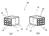
具体的には、枠体および格子状のリブを有する、例えば図1に示すような単一の成形品からなる衝撃エネルギ吸収体10や、図2に示すような、アウタ部11とインナ部とが別体で構成され、車両取り付け時にそれらを積み重ねて配置する衝撃エネルギ吸収体10を例示することができる。なお、図1、図2は、いずれも、(a)が衝撃エネルギ吸収体10を一方の側から見た斜視図であり、(b)が該衝撃エネルギ吸収体を他方の側から見た斜視図である。また、図1と図2に示す態様では、アウタ部11とインナ部とが一体成形品であるか別体であるかという違いがあるが、同じ呼称で説明する各部材は基本的に同一の作用効果を奏するものであり、図面においても同じ符号で示すこととする。
Specifically, for example, an impact energy absorber 10 made of a single molded product as shown in FIG. 1 having a frame body and grid-like ribs, an
図1に示す衝撃エネルギ吸収体10は、単一の成形品であって、枠体15の中に格子状のリブ13が設けられている。枠体15およびリブ13は、それぞれ、車両取り付け時の部品A(バンパカバー等)、衝撃エネルギ吸収体、部品B(フレーム等)の配列方向(以下、配列方向という)に延在している。
The impact energy absorber 10 shown in FIG. 1 is a single molded product, and a grid-
そして、本発明においては、車両取り付け時外側になるアウタ部と、内側になるインナ部のうち、オフセットされる部品Bから離れた位置に配置される一方が、次のようになっている。すなわち、車両取り付け時に前記配列方向に部品Bと重なる位置にあたるリブが、間引かれた状態、あるいは他のリブに比べて肉厚が薄い状態となっている。図1は、アウタ部11が、オフセットされる部品Bから離れた位置に配置されるものの態様であり、車両取り付け時に前記配列方向に部品B(フレーム等)と重なる位置にあたるリブが間引かれた状態(リブ間引き部14)になっている。このとき、当該部分のリブを間引かずに他のリブに比べて薄肉としても、上述したような効果が得られる。また、アウタ部ではなくインナ部が、オフセットされる部品Bから離れた位置に配置される場合には、アウタ部ではなくインナ部にリブ間引き部や薄肉リブを設ければよい。
And in this invention, one arrange | positioned in the position away from the components B offset among the outer part which becomes an outer side at the time of vehicle attachment, and the inner part which becomes an inner side is as follows. That is, the rib corresponding to the position overlapping the component B in the arrangement direction when the vehicle is mounted is thinned out or is thinner than other ribs. FIG. 1 shows an aspect in which the
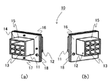
図2に示す衝撃エネルギ吸収体10も、アウタ部11とインナ部12とが別体であるという以外は、基本的に図1の衝撃エネルギ吸収体と同様の構成をしている。すなわち、アウタ部11、インナ部12それぞれが、枠体15の中に格子状のリブ13を設けた形態となっており、それらが車両取り付け時に積み重ねられて一つの衝撃エネルギ吸収体10を構成する。
The impact energy absorber 10 shown in FIG. 2 has basically the same configuration as the impact energy absorber shown in FIG. 1 except that the
枠体15およびリブ13は、それぞれ、車両取り付け時の部品A(バンパカバー等)、衝撃エネルギ吸収体、部品B(フレーム等)の配列方向に延在しており、アウタ部11、インナ部12のうち、オフセットされる部品Bから離れた位置に配置される一方の、車両取り付け時に前記配列方向に部品Bと重なる位置にあたるリブが、間引かれた状態、あるいは他のリブに比べて肉厚が薄い状態となっている。
The
図2は、アウタ部11が、オフセットされる部品Bから離れた位置に配置されるものの態様であり、車両取り付け時に前記配列方向に部品B(フレーム等)と重なる位置にあたるリブが間引かれた状態(リブ間引き部14)になっている。このとき、当該部分のリブを間引かずに他のリブに比べて薄肉としても、上述したような効果が得られる。また、アウタ部ではなくインナ部が、オフセットされる部品Bから離れた位置に配置される場合には、アウタ部ではなくインナ部にリブ間引き部や薄肉リブを設ければよい。
FIG. 2 shows an aspect in which the
図2に示すように、衝撃エネルギ吸収体のアウタ部およびインナ部を別体とする場合、アウタとインナの締結方法は特に限定されないが、スナップフィット、クリップ、ボルトなどで締結することが簡便で好ましい。そして、かかる締結のためには、図2に示すように、アウタ部11、インナ部12にフランジ部16を設け、当該フランジ部16にスナップフィット、クリップ、ボルトを取り付け、締結することが好ましい。
As shown in FIG. 2, when the outer part and the inner part of the impact energy absorber are separated, the fastening method of the outer and the inner is not particularly limited, but it is easy to fasten with a snap fit, a clip, a bolt, or the like. preferable. For such fastening, as shown in FIG. 2, it is preferable to provide a
これら衝撃エネルギ吸収体のアウタ部およびインナ部を構成する材料は、好ましくは樹脂組成物である。かかる樹脂組成物を構成する樹脂は特に限定されないが、好ましくは熱可塑性樹脂である。熱可塑性樹脂を使用することで、溶融成形が可能となり、生産性を向上させることができる。好ましい熱可塑性樹脂の例としては、ポリプロピレン、スチレン、ナイロン、ポリエステル、ポリカーボネイト、ポリアセタール、ポリウレタンなどが挙げられ、これらはポリマーアロイとして使用することもできる。 The material constituting the outer part and the inner part of these impact energy absorbers is preferably a resin composition. The resin constituting such a resin composition is not particularly limited, but is preferably a thermoplastic resin. By using a thermoplastic resin, melt molding becomes possible and productivity can be improved. Examples of preferred thermoplastic resins include polypropylene, styrene, nylon, polyester, polycarbonate, polyacetal, polyurethane and the like, and these can also be used as polymer alloys.
中でも、衝撃エネルギ吸収体を構成する樹脂として、熱可塑性樹脂(A)および反応性官能基を有する樹脂(B)を配合してなり、下記(I)および(II)の特徴を有する熱可塑性樹脂組成物を用いることが好ましい。
(I)引張試験における引張降伏伸度以降において、引張速度V1、V2の時の引張弾性率をE(V1)、E(V2)とすると、V1<V2のとき、E(V1)>E(V2)
(II)引張試験における引張降伏伸度以降において、引張伸度εにおけるV1、V2の時の応力をσ(V1、ε)、σ(V2、ε)とすると、V1<V2のとき、σ(V1、ε)>σ(V2、ε)
上記(I)、(II)を満足する熱可塑性樹脂組成物を、アウタ部、インナ部の構成材料として用いれば、衝突時等の急激な変形の際には靭性に優れた材料となるため、衝突時の衝撃エネルギ吸収量が大きくなる。
Among them, as a resin constituting the impact energy absorber, a thermoplastic resin (A) and a resin (B) having a reactive functional group are blended, and the thermoplastic resin having the following characteristics (I) and (II) It is preferable to use a composition.
(I) Assuming that the tensile elastic modulus at the tensile speeds V1 and V2 after the tensile yield elongation in the tensile test is E (V1) and E (V2), E (V1)> E ( V2)
(II) If the stress at V1 and V2 in the tensile elongation ε after the tensile yield elongation in the tensile test is σ (V1, ε) and σ (V2, ε), σ ( V1, ε)> σ (V2, ε)
If the thermoplastic resin composition satisfying the above (I) and (II) is used as a constituent material of the outer part and the inner part, it becomes a material excellent in toughness in the case of a sudden deformation such as a collision, The amount of impact energy absorbed at the time of collision increases.
なお、上記(I)および(II)の特徴を有する熱可塑性樹脂組成物としては、特開2006−089701号公報に示された熱可塑性樹脂組成物が挙げられる。この熱可塑性樹脂組成物は、二軸押出機のスクリュー長さをL、スクリュー直径をDとすると、L/D>45の二軸押出機を使用して熱可塑性樹脂(A)と反応性官能基を有する樹脂(B)とを溶融混練することによって製造され、下記(a)および(b)のどちらかに示す構造が形成されていることを特徴とする
(a)熱可塑性樹脂(A)および反応性官能基を有する樹脂(B)の一方が連続相、もう一方が分散相を形成し、さらにこれらの連続相および分散相中に平均粒子径300nm以下の微粒子が存在し、断面に占める分散相と連続相との面積比が40/60〜60/40である構造
(b)熱可塑性樹脂(A)および反応性官能基を有する樹脂(B)がともに連続相を形成し、さらにこれらの両連続相中に平均粒子径300nm以下の微粒子が存在し、断面に占める両連続相の面積比が40/60〜60/40である構造
ここで、熱可塑性樹脂(A)はポリアミド樹脂、ポリエステル樹脂、ポリフェニレンスルフィド樹脂、ポリアセタール樹脂、スチレン系樹脂から選ばれる少なくとも1種である熱可塑性樹脂組成物であり、反応性官能基を有する樹脂(B)は反応性官能基を有するゴム質重合体である熱可塑性樹脂組成物である。また、反応性官能基は、エポキシ基、酸無水物基、オキサゾリン基から選ばれる少なくとも1種以上の官能基である。
In addition, as a thermoplastic resin composition which has the characteristics of said (I) and (II), the thermoplastic resin composition shown by Unexamined-Japanese-Patent No. 2006-089701 is mentioned. This thermoplastic resin composition has a reactive function with the thermoplastic resin (A) using a twin screw extruder of L / D> 45, where L is the screw length of the twin screw extruder and D is the screw diameter. It is manufactured by melt-kneading a resin (B) having a group, and has a structure shown in either of the following (a) and (b): (a) Thermoplastic resin (A) And one of the resin (B) having a reactive functional group forms a continuous phase and the other forms a dispersed phase, and fine particles having an average particle diameter of 300 nm or less exist in these continuous phase and dispersed phase, and occupy the cross section. Structure in which area ratio of dispersed phase to continuous phase is 40/60 to 60/40 (b) The thermoplastic resin (A) and the resin (B) having a reactive functional group together form a continuous phase, and these Average particle diameter of 300 nm or less in both continuous phases In which the area ratio of both continuous phases in the cross section is 40/60 to 60/40. Here, the thermoplastic resin (A) is polyamide resin, polyester resin, polyphenylene sulfide resin, polyacetal resin, styrene. It is a thermoplastic resin composition that is at least one selected from a series resin, and the resin (B) having a reactive functional group is a thermoplastic resin composition that is a rubbery polymer having a reactive functional group. The reactive functional group is at least one functional group selected from an epoxy group, an acid anhydride group, and an oxazoline group.
かかる熱可塑性樹脂(A)と反応性官能基を有する樹脂(B)との配合比は、重量比で95/5〜5/95であることが好ましい。 The blending ratio between the thermoplastic resin (A) and the resin (B) having a reactive functional group is preferably 95/5 to 5/95 by weight.
なお、E(V1)、E(V2)およびσ(V1、ε)、σ(V2、ε)は、ASTM D−638−96規格に明記された引張試験の方法に従って測定される。Eは応力―ひずみ曲線の初期直線部分の勾配を示し、σは引張伸度εにおける応力を示す。また、図2に示すように、衝撃エネルギ吸収体のアウタ部およびインナ部を別体とする場合、それらを異なる材料で構成することもできる。すなわち、例えばアウタを構成する樹脂としてナイロン、インナを構成する樹脂としてポリプロピレンを使用することも可能である。 E (V1), E (V2), σ (V1, ε), and σ (V2, ε) are measured according to the tensile test method specified in the ASTM D-638-96 standard. E represents the slope of the initial straight line portion of the stress-strain curve, and σ represents the stress at the tensile elongation ε. Further, as shown in FIG. 2, when the outer part and the inner part of the impact energy absorber are separated, they can be made of different materials. That is, for example, nylon can be used as the resin constituting the outer, and polypropylene can be used as the resin constituting the inner.
そして、上記図1、図2に示すような衝撃エネルギ吸収体は、衝撃エネルギの吸収量を増大させるために、オフセットされる部品B近くの端面が閉口していることも好ましい。 In the impact energy absorber as shown in FIGS. 1 and 2, it is preferable that the end surface near the component B to be offset is closed in order to increase the amount of impact energy absorbed.
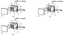
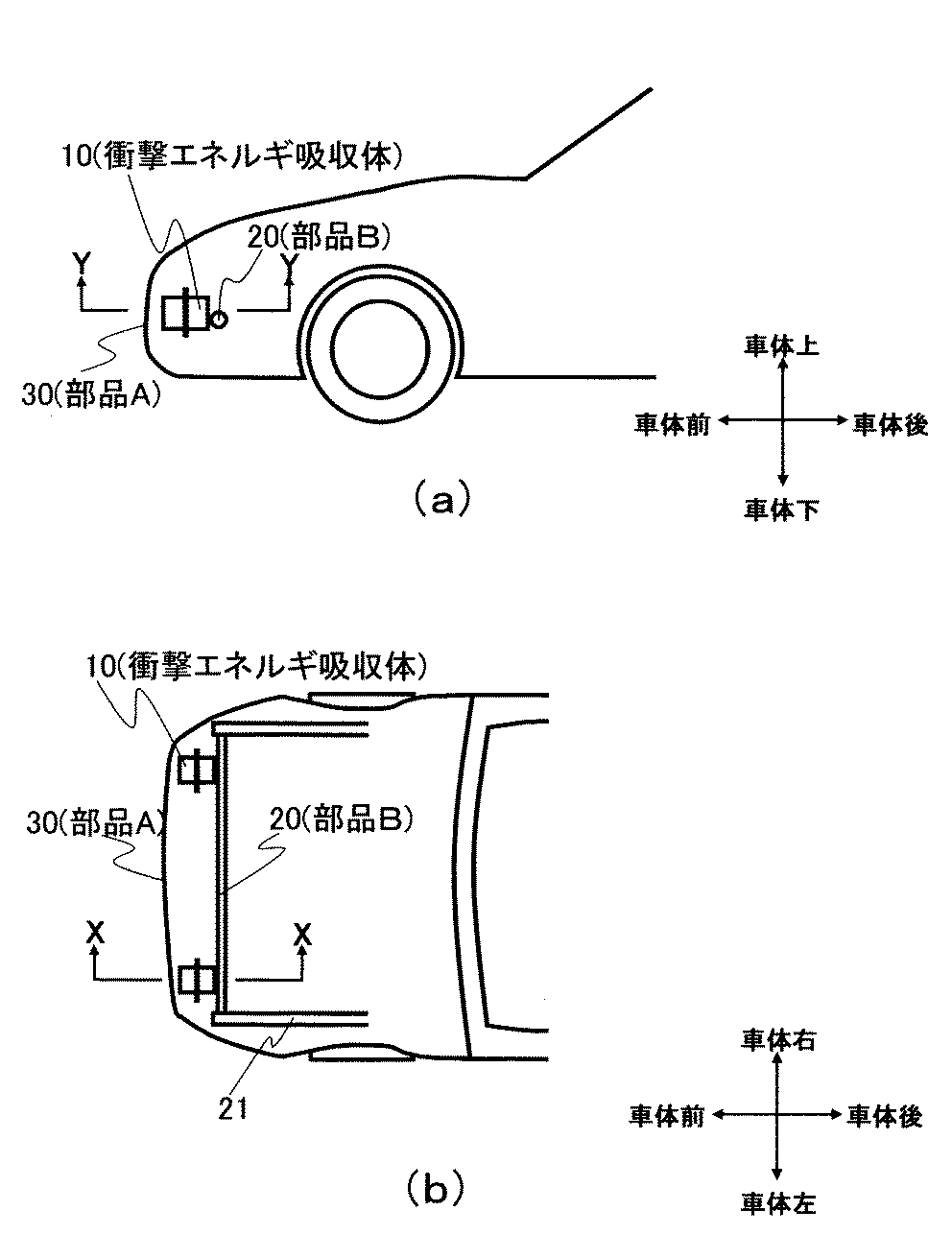
以上のような本発明の衝撃エネルギ吸収体は、例えば図3〜図5に示すように、車両に組み込まれる。図3〜図5は、図1に示すような本発明の一実施形態にかかる自動車用衝撃エネルギ吸収体にフランジ部16を設け、それを自動車に組み込んだ際の概略模式図であり、図3(a)が衝撃エネルギ吸収体周辺部分の車体水平方向の断面図、図3(b)が衝撃エネルギ吸収体周辺部分の車体上下方向の断面図、図4が衝撃エネルギ吸収体周辺部分の斜視図、図5(a)が車体の水平方向の断面図、図5(b)が車体の上下方向の断面図を示す。
The impact energy absorber of the present invention as described above is incorporated in a vehicle, for example, as shown in FIGS. 3 to 5 are schematic views when the
図3〜図5に示す態様において、衝撃エネルギ吸収体10は、衝撃エネルギ吸収体取り付け用治具40およびボルト41によってフレーム20に締結され、バンパカバー30(部品A)およびフレーム20(部品B)の間で、かつフレーム20とオフセットした位置に配置されている。なお、エネルギ吸収量を確保できるのであれば、締結方法は特に限定されない。また、図2に示すような、アウタ部11とインナ部12とが別体で構成されている衝撃エネルギ吸収体10を用いる場合も、図3〜図5と同様に組み込むことができる。
3 to 5, the
そして、本発明の衝撃エネルギ吸収体は、自動車等車両のバンパ内だけでなく、ドア内、フェンダ内など、耐衝撃性能が求められる場所であれば、いずれの場所でも使用できる。また、車両としては、自動二輪車、鉄道車両、船舶などを挙げることができる。なお、衝撃エネルギ吸収体の設計にあたっては、実際に試作、実験を行うことによって衝撃エネルギ吸収性能を確認し、その結果に基づいて最適な形状を決定することも可能であるが、コンピューターシミュレーションによる仮想的な試験結果に基づいて最適な形状を決定する方法が好ましく用いられる。 The impact energy absorber of the present invention can be used not only in a bumper of a vehicle such as an automobile but also in any location where impact resistance is required, such as in a door or in a fender. Examples of the vehicle include a motorcycle, a railway vehicle, and a ship. In designing the impact energy absorber, it is possible to confirm the impact energy absorption performance by actually making a prototype and experiment, and to determine the optimum shape based on the result, but it is possible to make a virtual simulation by computer simulation. A method of determining an optimum shape based on a typical test result is preferably used.
以下に実施例・比較例を示すが、本発明は、これに限定されるものではない。 Examples and Comparative Examples are shown below, but the present invention is not limited thereto.
実施例・比較例において、エネルギ吸収性能は図6に示すように評価した。すなわち、図6は衝突試験の模式図であり、50はインパクター、20はフレームである。この試験では、インパクター50が衝撃エネルギ吸収体10に衝突する際に、インパクター50の変位とインパクター50と衝撃エネルギ吸収体10の間に発生する反力を測定する。この荷重(反力)−変位線図の履歴面積が衝撃エネルギ吸収体のエネルギ吸収量になる。
In the examples and comparative examples, the energy absorption performance was evaluated as shown in FIG. That is, FIG. 6 is a schematic diagram of a collision test, 50 is an impactor, and 20 is a frame. In this test, when the impactor 50 collides with the
なお、インパクター50は重さ260kgの板(120mm×120mm×5mm)とし、衝突のスピードが5m/secとなるよう、衝撃エネルギ吸収体10に衝突させた。試験はバラツキが生じるため、N数は5回とし、エネルギ吸収量は5回の算術平均で評価した。
The impactor 50 was a plate having a weight of 260 kg (120 mm × 120 mm × 5 mm), and was made to collide with the
(実施例1)
図1に示す衝撃エネルギ吸収体10の中央部にフランジ部16を設け、図7に示すように固定し、対衝撃特性を評価した。
Example 1
The
なお、衝撃エネルギ吸収体10は、車両取り付け時にフレーム20から離れた位置に配置されるアウタ部11において、車両取り付け時に配列方向にフレーム20と重なる位置にあたるリブが、間引きされた状態となるように、東レ株式会社製ナイロン6樹脂“アミラン”UTN141を使用して、射出成形により成形した。70mm×70mm×高さ100mmの枠体15の、当該高さ方向中央には、120mm×120mmのフランジ部16を一体的に設け、さらに枠体15のフレーム20側の端面を閉口させた。枠体15の肉厚は2mm、リブ肉厚は2mm、フランジ肉厚も全て2mmとした。また、射出成形後にリブおよびアウタ部の枠体は開口側へ、インナ部の枠体は閉口側へ金型を離型できるよう、抜き勾配を設けた。得られた衝撃エネルギ吸収体10の重量は159gであった。
In the
この衝撃エネルギ吸収体10に対して、インパクター50を衝突させ、インパクター50が35mm変位したときのエネルギ吸収量を評価した。
An impactor 50 was made to collide with the
本発明の評価結果を図9(a)、図10、表1に示す。評価の結果、衝撃エネルギ吸収体10は、アウタ部11のリブが間引かれている部分が座屈することによって、フレーム20を支点にリブが間引きされていない方(車体上方向)に回転し、さらに、衝撃エネルギ吸収体10とフレーム20が接する部分でも座屈した。インパクター変位が35mmの時、衝撃エネルギ吸収体10が吸収するエネルギ量は、589.4Jとなった。このように、車両取り付け時にフレーム20から離れた位置に配置されるアウタ部11の、車両取り付け時に配列方向にフレーム20と重なる位置にあたるリブを間引くことによって、衝撃エネルギ吸収体10の軽量化をしつつ、衝撃エネルギ吸収体10の変形モードを制御することができる。
The evaluation results of the present invention are shown in FIG. 9 (a), FIG. As a result of the evaluation, the
(比較例1)
比較例1では、衝撃エネルギ吸収体内のリブを間引きせず、その他の条件に関しては、実施例1と同様にし、対衝撃特性を評価した。この時、衝撃エネルギ吸収体10の重量は164gであった。
(Comparative Example 1)
In Comparative Example 1, the ribs in the impact energy absorbing body were not thinned, and other conditions were the same as in Example 1 and the impact resistance characteristics were evaluated. At this time, the weight of the
評価の結果を、図9(b)、図10、表1に示す。評価の結果、衝撃エネルギ吸収体10は、フレーム20と接する部分で座屈し、フレーム20を支点に車体下方向に回転し、さらにフレーム20から車体上方向に外れる変形モードとなった。インパクター変位が35mmの時、衝撃エネルギ吸収体10が吸収するエネルギ量は、533.3Jとなり、実施例1に比べて、エネルギ吸収量は、56.1J小さくなった。また、重量は、実施例1に比べて、5g重くなった。
The evaluation results are shown in FIG. 9B, FIG. As a result of the evaluation, the
(比較例2)
車両取り付け時にフレーム20から離れた位置に配置されるアウタ部11の、車両取り付け時前記配列方向にフレーム20と重ならない位置に、リブ間引き部を設けた以外は、実施例1と同様にし、対衝撃特性を評価した。この時、衝撃エネルギ吸収体10の重量は159gであった。
(Comparative Example 2)
The
評価の結果を、図9(c)、図10、表1に示す。評価の結果、衝撃エネルギ吸収体10は、アウタ部11のリブが間引かれている部分が座屈することによって、フレーム20を支点にリブが間引きされていない方(車体下方向)に回転し、さらに衝撃エネルギ吸収体10とフレーム20が接する部分でも座屈した。これにより、衝撃エネルギ吸収体10は、比較例1よりもさらに、フレーム20から車体上方向に外れる変形モードとなった。インパクター変位が35mmの時、衝撃エネルギ吸収体10が吸収するエネルギ量は520.9Jとなり、実施例1に比べて、重量は同等でありながら、エネルギ吸収量は、68.5J小さくなった。
The results of the evaluation are shown in FIG. 9 (c), FIG. As a result of the evaluation, the
(実施例2)
衝撃エネルギ吸収体10を、図2に示すように2つの部品(アウタ部11とインナ部12)から構成し、図8(a)に示すように固定して対衝撃特性を評価した。
(Example 2)
The
なお、衝撃エネルギ吸収体10は、東レ株式会社製ナイロン6樹脂“アミラン”UTN141を使用して、射出成形により成形した。アウタ部11は、70mm×70mm×高さ50mmの枠体15の当該高さ方向の端面に、120mm×120mmのフランジ部16を一体的に設け、枠体15のフランジ部側端面を閉口し、フランジ部16と反対側の端面を開口させた。枠体肉厚は2mm、リブ肉厚は2mm、フランジ部肉厚は2mmであった。また、車両取り付け時に配列方向にフレーム20と重なる位置にあたるリブを、間引いた状態とした。一方、インナ部12は、リブを間引かず、枠体のフランジ部側を開口し、フランジ部16と反対側を閉口させた以外はアウタ部11と同様の外形寸法、肉厚とした。また、アウタ部11・インナ部12双方とも金型から離型できるように抜き勾配を設けた。このような別体のアウタ部11とインナ部12とをフランジ部16にあるスナップフィット17で締結し、衝撃エネルギ吸収体10とした。得られた衝撃エネルギ吸収体10の重量は203gであった。
The
この衝撃エネルギ吸収体10に対して、インパクター50を衝突させ、インパクター50が35mm変位したときのエネルギ吸収量を評価した。
An impactor 50 was made to collide with the
本発明の評価結果を図11、表2に示す。評価の結果、変形モードについては、実施例1の変形モード(図9(a))と同様、アウタ部11とインパクター50が接する部分において、リブが間引かれている部分が座屈することによって、衝撃エネルギ吸収体がフレーム20を支点にリブが間引きされていない方(車体上方向)に回転し、インナ部12とフレーム20が接する部分でも座屈した。インパクター変位が35mmの時、衝撃エネルギ吸収体10が吸収するエネルギ量は、489.4Jとなった。このようにアウタ11のリブを間引くことによって、衝撃エネルギ吸収体10の軽量化をしつつ、衝撃エネルギ吸収体10の変形モードを制御することができた。
The evaluation results of the present invention are shown in FIG. As a result of the evaluation, as for the deformation mode, as in the deformation mode of the first embodiment (FIG. 9A), the portion where the rib is thinned out in the portion where the
(比較例3)
アウタのリブを間引きせず、その他の条件に関しては、実施例2と同様にし、対衝撃特性を評価した。この時、衝撃エネルギ吸収体10の重量は207gであった。
(Comparative Example 3)
The outer ribs were not thinned, and the other conditions were the same as in Example 2, and the impact resistance characteristics were evaluated. At this time, the weight of the
評価の結果を、図11、表2に示す。評価の結果、変形モードについては、比較例1の変形モード(図9(b))と同様、インナ部12とフレーム20が接する部分で座屈し、衝撃エネルギ吸収体10は、フレーム20から車体上方向に外れる変形モードとなった。インパクター変位が35mmの時、衝撃エネルギ吸収体10が吸収するエネルギ量は、467.9Jとなり、実施例1に比べて、エネルギ吸収量は、21.5J小さくなった。また、重量は、実施例1に比べて、4g重くなった。
(比較例4)
車両に取り付け時にフレーム20から離れて配置されるアウタ部11の、車両取り付け時にアウタ部11とインナ部12の積み重ね方向にフレーム12と重ならない位置に、リブ間引き部を設けた以外は実施例2と同様にし、対衝撃特性を評価した。この時、衝撃エネルギ吸収体10の重量は203gであった。
The evaluation results are shown in FIG. As a result of the evaluation, the deformation mode is buckled at the portion where the
(Comparative Example 4)
Example 2 except that a rib thinning portion is provided at a position where the
評価の結果を、図11、表2に示す。評価の結果、変形モードについては、比較例2の変形モード(図9(c))と同様、アウタ部11のリブが間引かれている部分が座屈することによって、衝撃エネルギ吸収体10としては、フレームを支点にリブが間引きされていない方(車体下方向)に回転し、インナ12もフレーム20と接する部分で座屈した。これにより、衝撃エネルギ吸収体10は、比較例1よりもさらに、フレーム20から車体上方向に外れる変形モードとなった。インパクター変位が35mmの時、衝撃エネルギ吸収体10が吸収するエネルギ量は458.8Jとなり、実施例1に比べて、重量は同等でありながら、エネルギ吸収量は、30.6J小さくなった。
The evaluation results are shown in FIG. As a result of the evaluation, as for the deformation mode, as in the deformation mode of Comparative Example 2 (FIG. 9C), the
本発明の衝撃エネルギ吸収体は、自動二輪車、鉄道車両、船舶などに用いることができる。 The impact energy absorber of the present invention can be used for motorcycles, railway vehicles, ships and the like.
10:衝撃エネルギ吸収体
11:アウタ部
12:インナ部
13:リブ
14:リブ間引き部
15:枠体
16:フランジ部
17:スナップフィット
18:ボルト締結用穴
20:フレーム(部品B)
21:サイドメンバ
30:バンパカバー(部品A)
40:衝撃エネルギ吸収体取り付け用治具
41:衝撃エネルギ吸収体取り付け用ボルト
50:インパクター
10: Impact energy absorber 11: Outer part 12: Inner part 13: Rib 14: Rib thinning part 15: Frame body 16: Flange part 17: Snap fit 18: Bolt fastening hole 20: Frame (component B)
21: Side member 30: Bumper cover (part A)
40: Impact energy absorber mounting jig 41: Impact energy absorber mounting bolt 50: Impactor
Claims (4)
(I)引張試験における引張降伏伸度以降において、引張速度V1、V2の時の引張弾性率をE(V1)、E(V2)とすると、V1<V2のとき、E(V1)>E(V2)
(II)引張試験における引張降伏伸度以降において、引張伸度εにおけるV1、V2の時の応力をσ(V1、ε)、σ(V2、ε)とすると、V1<V2のとき、σ(V1、ε)>σ(V2、ε) The outer part and the inner part are composed of a thermoplastic resin (A) and a resin (B) having a reactive functional group, and satisfy the following relationships (I) and (II): The impact energy absorber according to claim 1, comprising:
(I) Assuming that the tensile elastic modulus at the tensile speeds V1 and V2 after the tensile yield elongation in the tensile test is E (V1) and E (V2), E (V1)> E ( V2)
(II) If the stress at V1 and V2 in the tensile elongation ε after the tensile yield elongation in the tensile test is σ (V1, ε) and σ (V2, ε), σ ( V1, ε)> σ (V2, ε)
Priority Applications (1)
| Application Number | Priority Date | Filing Date | Title |
|---|---|---|---|
| JP2008168294A JP5240556B2 (en) | 2008-06-27 | 2008-06-27 | Impact energy absorber |
Applications Claiming Priority (1)
| Application Number | Priority Date | Filing Date | Title |
|---|---|---|---|
| JP2008168294A JP5240556B2 (en) | 2008-06-27 | 2008-06-27 | Impact energy absorber |
Publications (2)
| Publication Number | Publication Date |
|---|---|
| JP2010006245A true JP2010006245A (en) | 2010-01-14 |
| JP5240556B2 JP5240556B2 (en) | 2013-07-17 |
Family
ID=41587227
Family Applications (1)
| Application Number | Title | Priority Date | Filing Date |
|---|---|---|---|
| JP2008168294A Active JP5240556B2 (en) | 2008-06-27 | 2008-06-27 | Impact energy absorber |
Country Status (1)
| Country | Link |
|---|---|
| JP (1) | JP5240556B2 (en) |
Cited By (3)
| Publication number | Priority date | Publication date | Assignee | Title |
|---|---|---|---|---|
| WO2011115148A1 (en) * | 2010-03-17 | 2011-09-22 | 日軽金アクト株式会社 | Bumper stay |
| KR101198604B1 (en) | 2011-03-10 | 2012-11-07 | 주식회사 성우하이텍 | Bumper stay unit of automotive bumper unit |
| KR101253124B1 (en) * | 2011-05-30 | 2013-05-22 | 주식회사 아펙스 | Stay for bumper of car |
Citations (7)
| Publication number | Priority date | Publication date | Assignee | Title |
|---|---|---|---|---|
| JPS5345637U (en) * | 1976-09-21 | 1978-04-18 | ||
| JPH04287741A (en) * | 1991-03-18 | 1992-10-13 | Suzuki Motor Corp | Energy absorber of bumper for vehicle |
| JPH0655893U (en) * | 1993-01-09 | 1994-08-02 | サカエ理研工業株式会社 | Energy absorbing plastic bumper |
| JP2001208120A (en) * | 1999-11-02 | 2001-08-03 | Toray Ind Inc | Shock energy absorbing member made of fiber reinforced plastic |
| JP2006089701A (en) * | 2004-08-27 | 2006-04-06 | Toray Ind Inc | Thermoplastic resin composition and method for producing the same |
| JP2006192982A (en) * | 2005-01-11 | 2006-07-27 | Fuji Heavy Ind Ltd | Vehicle body structure |
| JP2007290499A (en) * | 2006-04-24 | 2007-11-08 | Toyota Motor Corp | Bumper absorber |
-
2008
- 2008-06-27 JP JP2008168294A patent/JP5240556B2/en active Active
Patent Citations (7)
| Publication number | Priority date | Publication date | Assignee | Title |
|---|---|---|---|---|
| JPS5345637U (en) * | 1976-09-21 | 1978-04-18 | ||
| JPH04287741A (en) * | 1991-03-18 | 1992-10-13 | Suzuki Motor Corp | Energy absorber of bumper for vehicle |
| JPH0655893U (en) * | 1993-01-09 | 1994-08-02 | サカエ理研工業株式会社 | Energy absorbing plastic bumper |
| JP2001208120A (en) * | 1999-11-02 | 2001-08-03 | Toray Ind Inc | Shock energy absorbing member made of fiber reinforced plastic |
| JP2006089701A (en) * | 2004-08-27 | 2006-04-06 | Toray Ind Inc | Thermoplastic resin composition and method for producing the same |
| JP2006192982A (en) * | 2005-01-11 | 2006-07-27 | Fuji Heavy Ind Ltd | Vehicle body structure |
| JP2007290499A (en) * | 2006-04-24 | 2007-11-08 | Toyota Motor Corp | Bumper absorber |
Cited By (4)
| Publication number | Priority date | Publication date | Assignee | Title |
|---|---|---|---|---|
| WO2011115148A1 (en) * | 2010-03-17 | 2011-09-22 | 日軽金アクト株式会社 | Bumper stay |
| JP2011189915A (en) * | 2010-03-17 | 2011-09-29 | Nikkeikin Aluminium Core Technology Co Ltd | Bumper stay |
| KR101198604B1 (en) | 2011-03-10 | 2012-11-07 | 주식회사 성우하이텍 | Bumper stay unit of automotive bumper unit |
| KR101253124B1 (en) * | 2011-05-30 | 2013-05-22 | 주식회사 아펙스 | Stay for bumper of car |
Also Published As
| Publication number | Publication date |
|---|---|
| JP5240556B2 (en) | 2013-07-17 |
Similar Documents
| Publication | Publication Date | Title |
|---|---|---|
| US8474583B2 (en) | Impact device and methods of making and using the same | |
| US9434334B2 (en) | Reinforced plastic energy absorber system and methods of making the same | |
| US20120126563A1 (en) | Glove box structure for vehicle | |
| US20120104778A1 (en) | Unitary energy absorbing assembly and method of making the same | |
| KR101095988B1 (en) | Crash box type bumper | |
| JP2003048585A (en) | Impact absorber for two-wheeled vehicle | |
| JP2008526590A (en) | Bumper system with energy absorber | |
| JP5471519B2 (en) | Automotive hood | |
| US8075048B2 (en) | Bonnet for automobile having automobiles that protects the heads of pedestrians | |
| JP4736609B2 (en) | Car fender panel mounting structure | |
| JP5240556B2 (en) | Impact energy absorber | |
| US6729451B2 (en) | Shock absorber for a two-wheeled vehicle | |
| JP2009515772A (en) | Energy absorbing vehicle fender | |
| JP5820453B2 (en) | Front body structure | |
| JP2005178682A (en) | Body front structure of automobile | |
| JP2011063082A (en) | Shock energy absorbing body | |
| JP2005520735A (en) | Automotive bumper beam with energy absorber | |
| WO2017135407A1 (en) | Vehicle interior component | |
| JP5358196B2 (en) | Body front structure | |
| JP5625564B2 (en) | Support structure for vehicle parts | |
| JP6016246B2 (en) | Auto body structure | |
| JP2009073447A (en) | Bumper | |
| US20210291639A1 (en) | Air guide for a motor vehicle, made of a piece of expanded polymer material, and comprising impact absorbing zones | |
| WO2020149296A1 (en) | Automobile door | |
| JP4880308B2 (en) | Shock absorbing member for vehicle |
Legal Events
| Date | Code | Title | Description |
|---|---|---|---|
| A621 | Written request for application examination |
Free format text: JAPANESE INTERMEDIATE CODE: A621 Effective date: 20110527 |
|
| RD03 | Notification of appointment of power of attorney |
Free format text: JAPANESE INTERMEDIATE CODE: A7423 Effective date: 20120720 |
|
| A977 | Report on retrieval |
Effective date: 20120928 Free format text: JAPANESE INTERMEDIATE CODE: A971007 |
|
| A131 | Notification of reasons for refusal |
Free format text: JAPANESE INTERMEDIATE CODE: A131 Effective date: 20121002 |
|
| A521 | Written amendment |
Free format text: JAPANESE INTERMEDIATE CODE: A523 Effective date: 20121116 |
|
| TRDD | Decision of grant or rejection written | ||
| A01 | Written decision to grant a patent or to grant a registration (utility model) |
Effective date: 20130308 Free format text: JAPANESE INTERMEDIATE CODE: A01 |
|
| A61 | First payment of annual fees (during grant procedure) |
Free format text: JAPANESE INTERMEDIATE CODE: A61 Effective date: 20130321 |
|
| FPAY | Renewal fee payment (prs date is renewal date of database) |
Free format text: PAYMENT UNTIL: 20160412 Year of fee payment: 3 |
|
| FPAY | Renewal fee payment (prs date is renewal date of database) |
Year of fee payment: 3 Free format text: PAYMENT UNTIL: 20160412 |