JP2010004631A - Electric vehicle and ground fault detection method in the electric vehicle - Google Patents
Electric vehicle and ground fault detection method in the electric vehicle Download PDFInfo
- Publication number
- JP2010004631A JP2010004631A JP2008160156A JP2008160156A JP2010004631A JP 2010004631 A JP2010004631 A JP 2010004631A JP 2008160156 A JP2008160156 A JP 2008160156A JP 2008160156 A JP2008160156 A JP 2008160156A JP 2010004631 A JP2010004631 A JP 2010004631A
- Authority
- JP
- Japan
- Prior art keywords
- ground fault
- fuel cell
- electric vehicle
- insulation resistance
- idle stop
- Prior art date
- Legal status (The legal status is an assumption and is not a legal conclusion. Google has not performed a legal analysis and makes no representation as to the accuracy of the status listed.)
- Granted
Links
Images


Classifications
-
- H—ELECTRICITY
- H01—ELECTRIC ELEMENTS
- H01M—PROCESSES OR MEANS, e.g. BATTERIES, FOR THE DIRECT CONVERSION OF CHEMICAL ENERGY INTO ELECTRICAL ENERGY
- H01M8/00—Fuel cells; Manufacture thereof
- H01M8/04—Auxiliary arrangements, e.g. for control of pressure or for circulation of fluids
- H01M8/04298—Processes for controlling fuel cells or fuel cell systems
- H01M8/043—Processes for controlling fuel cells or fuel cell systems applied during specific periods
-
- B—PERFORMING OPERATIONS; TRANSPORTING
- B60—VEHICLES IN GENERAL
- B60L—PROPULSION OF ELECTRICALLY-PROPELLED VEHICLES; SUPPLYING ELECTRIC POWER FOR AUXILIARY EQUIPMENT OF ELECTRICALLY-PROPELLED VEHICLES; ELECTRODYNAMIC BRAKE SYSTEMS FOR VEHICLES IN GENERAL; MAGNETIC SUSPENSION OR LEVITATION FOR VEHICLES; MONITORING OPERATING VARIABLES OF ELECTRICALLY-PROPELLED VEHICLES; ELECTRIC SAFETY DEVICES FOR ELECTRICALLY-PROPELLED VEHICLES
- B60L3/00—Electric devices on electrically-propelled vehicles for safety purposes; Monitoring operating variables, e.g. speed, deceleration or energy consumption
- B60L3/0023—Detecting, eliminating, remedying or compensating for drive train abnormalities, e.g. failures within the drive train
- B60L3/0069—Detecting, eliminating, remedying or compensating for drive train abnormalities, e.g. failures within the drive train relating to the isolation, e.g. ground fault or leak current
-
- B—PERFORMING OPERATIONS; TRANSPORTING
- B60—VEHICLES IN GENERAL
- B60L—PROPULSION OF ELECTRICALLY-PROPELLED VEHICLES; SUPPLYING ELECTRIC POWER FOR AUXILIARY EQUIPMENT OF ELECTRICALLY-PROPELLED VEHICLES; ELECTRODYNAMIC BRAKE SYSTEMS FOR VEHICLES IN GENERAL; MAGNETIC SUSPENSION OR LEVITATION FOR VEHICLES; MONITORING OPERATING VARIABLES OF ELECTRICALLY-PROPELLED VEHICLES; ELECTRIC SAFETY DEVICES FOR ELECTRICALLY-PROPELLED VEHICLES
- B60L58/00—Methods or circuit arrangements for monitoring or controlling batteries or fuel cells, specially adapted for electric vehicles
- B60L58/30—Methods or circuit arrangements for monitoring or controlling batteries or fuel cells, specially adapted for electric vehicles for monitoring or controlling fuel cells
-
- H—ELECTRICITY
- H01—ELECTRIC ELEMENTS
- H01M—PROCESSES OR MEANS, e.g. BATTERIES, FOR THE DIRECT CONVERSION OF CHEMICAL ENERGY INTO ELECTRICAL ENERGY
- H01M8/00—Fuel cells; Manufacture thereof
- H01M8/04—Auxiliary arrangements, e.g. for control of pressure or for circulation of fluids
- H01M8/04298—Processes for controlling fuel cells or fuel cell systems
- H01M8/04313—Processes for controlling fuel cells or fuel cell systems characterised by the detection or assessment of variables; characterised by the detection or assessment of failure or abnormal function
- H01M8/04537—Electric variables
- H01M8/04634—Other electric variables, e.g. resistance or impedance
-
- H—ELECTRICITY
- H01—ELECTRIC ELEMENTS
- H01M—PROCESSES OR MEANS, e.g. BATTERIES, FOR THE DIRECT CONVERSION OF CHEMICAL ENERGY INTO ELECTRICAL ENERGY
- H01M2250/00—Fuel cells for particular applications; Specific features of fuel cell system
- H01M2250/20—Fuel cells in motive systems, e.g. vehicle, ship, plane
-
- Y—GENERAL TAGGING OF NEW TECHNOLOGICAL DEVELOPMENTS; GENERAL TAGGING OF CROSS-SECTIONAL TECHNOLOGIES SPANNING OVER SEVERAL SECTIONS OF THE IPC; TECHNICAL SUBJECTS COVERED BY FORMER USPC CROSS-REFERENCE ART COLLECTIONS [XRACs] AND DIGESTS
- Y02—TECHNOLOGIES OR APPLICATIONS FOR MITIGATION OR ADAPTATION AGAINST CLIMATE CHANGE
- Y02E—REDUCTION OF GREENHOUSE GAS [GHG] EMISSIONS, RELATED TO ENERGY GENERATION, TRANSMISSION OR DISTRIBUTION
- Y02E60/00—Enabling technologies; Technologies with a potential or indirect contribution to GHG emissions mitigation
- Y02E60/30—Hydrogen technology
- Y02E60/50—Fuel cells
-
- Y—GENERAL TAGGING OF NEW TECHNOLOGICAL DEVELOPMENTS; GENERAL TAGGING OF CROSS-SECTIONAL TECHNOLOGIES SPANNING OVER SEVERAL SECTIONS OF THE IPC; TECHNICAL SUBJECTS COVERED BY FORMER USPC CROSS-REFERENCE ART COLLECTIONS [XRACs] AND DIGESTS
- Y02—TECHNOLOGIES OR APPLICATIONS FOR MITIGATION OR ADAPTATION AGAINST CLIMATE CHANGE
- Y02T—CLIMATE CHANGE MITIGATION TECHNOLOGIES RELATED TO TRANSPORTATION
- Y02T90/00—Enabling technologies or technologies with a potential or indirect contribution to GHG emissions mitigation
- Y02T90/40—Application of hydrogen technology to transportation, e.g. using fuel cells
Abstract
Description
この発明は、燃料電池と電動機の駆動回路との間の地絡を検知する地絡検知装置を備えた電気車両と、該電気車両での地絡検出方法とに関する。 The present invention relates to an electric vehicle including a ground fault detection device that detects a ground fault between a fuel cell and a drive circuit of an electric motor, and a ground fault detection method in the electric vehicle.
従来、非接地の燃料電池の出力側に地絡検知装置を並列に接続し、該出力側で地絡が発生したときに、前記地絡検知装置内の抵抗器を流れる電流によって該抵抗器に発生する電圧が設定電圧よりも高ければ、前記出力側に接続された遮断器を動作させて前記燃料電池に対する地絡保護を行うことが提案されている(特許文献1参照)。 Conventionally, a ground fault detection device is connected in parallel to the output side of a non-grounded fuel cell, and when a ground fault occurs on the output side, current is passed through the resistor in the ground fault detection device to the resistor. If the generated voltage is higher than a set voltage, it has been proposed to operate a circuit breaker connected to the output side to perform ground fault protection for the fuel cell (see Patent Document 1).
ところで、電動機による車輪の回転によって走行する電気車両において、例えば、渋滞走行のように、燃料電池の通常運転と、燃料電池運転の一時休止(以下、アイドル停止という。)とが繰り返される場合に、アイドル停止時の前記燃料電池の出力電圧は、通常運転時の出力電圧よりも低くなるので、特許文献1の地絡検知装置を前記電気車両に適用した場合には、前記通常運転と前記アイドル停止との繰り返しによる前記出力電圧の変化に起因した抵抗器での電圧の変化により、前記燃料電池と前記駆動回路との間に発生する地絡を正確且つ速やかに検出することができない。
By the way, in an electric vehicle that travels by the rotation of a wheel by an electric motor, for example, when a normal operation of a fuel cell and a pause of a fuel cell operation (hereinafter referred to as idle stop) are repeated as in a traffic jam, Since the output voltage of the fuel cell at the time of idling stop is lower than the output voltage at the time of normal operation, when the ground fault detection device of
この発明は、このような課題を考慮してなされたものであり、正確且つ速やかに地絡を検出することができる電気車両及び該電気車両での地絡検出方法を提供することを目的とする。 The present invention has been made in consideration of such problems, and an object thereof is to provide an electric vehicle capable of accurately and quickly detecting a ground fault and a ground fault detection method in the electric vehicle. .
この発明は、燃料電池と、前記燃料電池に駆動回路を介して接続され且つ車輪を回転させる電動機と、前記燃料電池と前記駆動回路との間の地絡を検知する地絡検知装置と、前記燃料電池、前記駆動回路及び前記電動機を制御する制御部とを備える電気車両において、前記地絡検知装置は、前記地絡の発生箇所と接地との間の絶縁抵抗を算出し、算出した前記絶縁抵抗がアイドル停止禁止閾値よりも低ければ、前記絶縁抵抗が前記アイドル停止禁止閾値よりも低いことを示す検出結果を前記制御部に出力し、前記制御部は、入力された前記検出結果に基づいて前記燃料電池のアイドル停止を禁止することを特徴としている。 The present invention includes a fuel cell, an electric motor connected to the fuel cell via a drive circuit and rotating a wheel, a ground fault detection device for detecting a ground fault between the fuel cell and the drive circuit, In an electric vehicle including a fuel cell, the drive circuit, and a control unit that controls the electric motor, the ground fault detection device calculates an insulation resistance between the occurrence point of the ground fault and the ground, and calculates the calculated insulation If the resistance is lower than the idle stop prohibition threshold, the detection result indicating that the insulation resistance is lower than the idle stop prohibition threshold is output to the control unit, and the control unit is based on the input detection result. The fuel cell is prohibited from being idled.
また、この発明に係る電気車両での地絡検出方法は、車輪を回転させる電動機が駆動回路を介して燃料電池に接続される電気車両で、前記燃料電池と前記駆動回路との間の地絡を検知する場合に、前記地絡の発生箇所と接地との間の絶縁抵抗を算出し、算出した前記絶縁抵抗がアイドル停止禁止閾値よりも低ければ、前記燃料電池のアイドル停止を禁止することを特徴としている。 The ground fault detection method for an electric vehicle according to the present invention is an electric vehicle in which an electric motor for rotating a wheel is connected to a fuel cell via a drive circuit, and the ground fault between the fuel cell and the drive circuit. Is detected, the insulation resistance between the ground fault occurrence point and the ground is calculated, and if the calculated insulation resistance is lower than the idle stop prohibition threshold, the fuel cell is prohibited from idling. It is a feature.
これらの発明によれば、前記絶縁抵抗が前記アイドル停止禁止閾値よりも低ければ、前記アイドル停止を禁止するので、正確且つ速やかに前記地絡を検出することができる。 According to these inventions, if the insulation resistance is lower than the idle stop prohibition threshold, the idle stop is prohibited, so that the ground fault can be detected accurately and promptly.
ここで、前記制御部は、前記検出結果に基づいて、前記燃料電池が運転されている状態から、前記アイドル停止への移行を禁止するか、あるいは、前記検出結果に基づいて、前記アイドル停止を解除し、前記燃料電池の運転を開始することが好ましい。 Here, the control unit prohibits the transition from the operating state of the fuel cell to the idle stop based on the detection result, or performs the idle stop based on the detection result. It is preferable to cancel and start the operation of the fuel cell.
これにより、前記地絡が発生している場合には、該地絡を確実に検出することが可能となり、一方で、前記地絡が発生していない場合には、該地絡が誤検出されることを確実に防止することができる。 As a result, when the ground fault occurs, the ground fault can be reliably detected. On the other hand, when the ground fault does not occur, the ground fault is erroneously detected. Can be reliably prevented.
また、前記地絡検知装置は、前記燃料電池に並列に接続された抵抗器及びコンデンサの直列回路と、前記コンデンサの充電電圧を計測し、計測した前記充電電圧に基づいて前記地絡の発生を検知する地絡検知部とを有し、
前記地絡検知部は、前記地絡が発生していないときの充電電圧(以下、第1充電電圧という。)を予め計測し、前記地絡が発生したときの充電電圧(以下、第2充電電圧という。)を計測し、前記第1充電電圧と前記第2充電電圧との比率に基づいて前記絶縁抵抗を算出し、算出した前記絶縁抵抗が前記アイドル停止禁止閾値よりも低い場合に前記検出結果を前記制御部に出力し、前記アイドル停止禁止閾値より低く設定された地絡確定閾値よりも前記絶縁抵抗が低い場合に前記地絡の発生を前記制御部に通知する。
In addition, the ground fault detection device measures a charging voltage of the capacitor and a series circuit of a resistor and a capacitor connected in parallel to the fuel cell, and generates the ground fault based on the measured charging voltage. A ground fault detection unit to detect,
The ground fault detection unit measures in advance a charging voltage when the ground fault has not occurred (hereinafter referred to as a first charging voltage), and a charging voltage when the ground fault has occurred (hereinafter referred to as a second charging). The insulation resistance is calculated based on a ratio between the first charging voltage and the second charging voltage, and the detection is performed when the calculated insulation resistance is lower than the idle stop prohibition threshold. The result is output to the control unit, and the control unit is notified of the occurrence of the ground fault when the insulation resistance is lower than the ground fault determination threshold value set lower than the idle stop prohibition threshold value.
これにより、前記地絡を精度よく検出することができる。 Thereby, the ground fault can be detected with high accuracy.
また、前記燃料電池と前記駆動回路との間に、前記燃料電池から前記駆動回路を介して前記電動機に電力を供給するためのダイオードが配置され、前記駆動回路に、前記制御部により制御されるDC/DCコンバータを介して蓄電装置が、前記ダイオード及び前記燃料電池に対して並列に接続されている場合に、前記地絡検知装置を、前記燃料電池と前記ダイオードとの間に接続するか、あるいは、前記ダイオードと前記駆動回路との間に接続すれば、前記燃料電池と前記駆動回路との間の前記地絡の発生をより確実に検出することができる。 In addition, a diode for supplying power from the fuel cell to the electric motor via the drive circuit is disposed between the fuel cell and the drive circuit, and the drive circuit is controlled by the control unit. When a power storage device is connected in parallel to the diode and the fuel cell via a DC / DC converter, the ground fault detection device is connected between the fuel cell and the diode, Or if it connects between the said diode and the said drive circuit, generation | occurrence | production of the said ground fault between the said fuel cell and the said drive circuit can be detected more reliably.
この発明によれば、絶縁抵抗がアイドル停止禁止閾値よりも低ければ、アイドル停止を禁止するので、正確且つ速やかに地絡を検出することができる。 According to the present invention, if the insulation resistance is lower than the idle stop prohibition threshold, the idle stop is prohibited, so that a ground fault can be detected accurately and promptly.
以下、この発明の一実施形態について図面を参照して説明する。 Hereinafter, an embodiment of the present invention will be described with reference to the drawings.
図1は、この発明の一実施形態に係る燃料電池車両(電気車両)10の回路図である。 FIG. 1 is a circuit diagram of a fuel cell vehicle (electric vehicle) 10 according to an embodiment of the present invention.
燃料電池車両10は、基本的には、第1電圧V1を発生する発電装置としての燃料電池12と、燃料電池12の出力ライン14a、14bに接続されたインバータ(駆動回路)16と、インバータ16に接続されたモータ(電動機)18と、バッテリ38と、バッテリ38の出力ライン42a、42bに接続され且つ出力ライン40a、40bが出力ライン14a、14bに接続されたDC/DCコンバータ36と、燃料電池12、インバータ16、モータ18及びDC/DCコンバータ36を制御する制御部46とを有する。この場合、燃料電池車両10のうち、燃料電池12からモータ18まで、及び、燃料電池12及びモータ18からバッテリ38までは、非接地とされている。
The
出力ライン14aにはコンタクタ34及び逆流防止用のダイオード28が配置され、出力ライン42aにはコンタクタ44が配置され、出力ライン14a、14b間には、第1電圧V1及び第2電圧V2をそれぞれ検出して制御部46に出力する電圧センサ30、32が燃料電池12及びインバータ16に対して並列に接続されている。
A
燃料電池12は、例えば、固体高分子電解質膜をアノード電極とカソード電極とで両側から挟み込んで形成されたセルを積層したスタック構造であり、制御部46によってコンタクタ34が閉状態にあるときに、水素(燃料ガス)と空気(酸化剤ガス)との電気化学反応により生成された第1電流I1(発電電流)をダイオード28を介してインバータ16及び(又は)DC/DCコンバータ36に供給する。インバータ16は、直流/交流変換を行って、第2電流I2(モータ電流)をモータ18に供給する一方、回生動作に伴う交流/直流変換後の第2電流I2をDC/DCコンバータ36を通じてバッテリ38に供給する。
The
モータ18は、燃料電池12からダイオード28及びインバータ16を介しての電力供給、あるいは、バッテリ38からDC/DCコンバータ36及びインバータ16を介しての電力供給により回転し、該モータ18の回転は、減速機20、シャフト22を通じて車輪24に伝達され、車輪24を回転させる。バッテリ38は、例えば、リチウムイオン2次電池、ニッケル水素2次電池又はキャパシタであり、第3電圧V3(バッテリ電圧)を発生し、制御部46によってコンタクタ44が閉状態にあるときに、モータ18の回転時にはモータ18に電力供給を行い、一方で、モータ18の回生時には充電される。
The
第2電流I2は、第1電流I1と、バッテリ38から流れ出た第3電流I3(バッテリ電流)がDC/DCコンバータ36により変換された電流I3´との合成電流(I2=I1+I3´)である。また、制御部46は、燃料電池12の電力分担と、バッテリ38の電力分担と、モータ18の電力分担との配分を決定し、この決定に基づいて燃料電池12、DC/DCコンバータ36、インバータ16及びモータ18を制御することにより、各電圧V1〜V3及び各電流I1〜I3´を制御する。車速センサ48は、燃料電池車両10の車速を示す車速信号Ssを制御部46に供給する。
The second current I2 is a combined current (I2 = I1 + I3 ′) of the first current I1 and the current I3 ′ obtained by converting the third current I3 (battery current) flowing out of the
さらに、燃料電池車両10には、出力ライン14a、14bに地絡が発生したときに、地絡発生箇所と接地との間の絶縁抵抗R(図1〜図3の絶縁抵抗R1、R2を含む燃料電池車両10全体としての絶縁抵抗)の低下を検出(検知)して、その検出結果を検知信号Sdとして制御部46に供給する地絡センサ26が、出力ライン14a、14b間で、燃料電池12及びインバータ16に対して並列に接続されている。この場合、制御部46は、入力された検知信号Sdに基づいて、燃料電池12のアイドル停止を禁止し、あるいは、地絡の発生を外部に警告する。
Furthermore, the
なお、図1では、ダイオード28とインバータ16との間の出力ライン14a、14b間に地絡センサ26が接続され、出力ライン14a中、燃料電池12とダイオード28との間、及び、ダイオード28とインバータ16との間に地絡がそれぞれ発生している(地絡発生箇所54、56がそれぞれ存在する)場合を図示している。図1では、地絡発生箇所54と接地との間を、絶縁抵抗R1を有する仮想的な抵抗器50として図示し、一方で、地絡発生箇所56と接地との間を、絶縁抵抗R2を有する仮想的な抵抗器52として図示している。また、この実施形態は、図2に示すように、燃料電池12とダイオード28との間の出力ライン14a、14b間に地絡センサ26を接続してもよい。また、図3に示すように、ダイオード28が出力ライン14a、14b間に配置されたDC/DCコンバータ58内のダイオードでもよい。
In FIG. 1, a
次に、地絡発生時における地絡発生箇所と接地との間の絶縁抵抗R(前述したように複数の地絡発生箇所54、56が存在する場合には、絶縁抵抗R1、R2を含む燃料電池車両10全体としての絶縁抵抗R)の検出原理について、図4〜図7を参照しながら説明する。
Next, the insulation resistance R between the ground fault occurrence location and the ground when the ground fault occurs (if there are a plurality of ground
地絡センサ26は、図4に示すように、燃料電池12に対して並列に接続された抵抗器60及びコンデンサ62の直列回路と、コンデンサ62に接続された地絡検知部64と、出力ライン14aと抵抗器60とを接続するためのスイッチ66aと、コンデンサ62と出力ライン14bとを接続するためのスイッチ66bと、コンデンサ62の負極側を接地するためのスイッチ66cとを有する。
As shown in FIG. 4, the
地絡センサ26は、先ず、出力ライン14a、14bで地絡が発生していない状態(図4参照)において第1電圧V1の計測を行う。具体的には、コンタクタ34及びスイッチ66a、66bがそれぞれ閉状態で、且つ、スイッチ66cが開状態であるときに、燃料電池12の正極からコンタクタ34、スイッチ66a、抵抗器60、コンデンサ62、スイッチ66b及び燃料電池12の負極の順に流れる電流Iによってコンデンサ62に発生する第1充電電圧Vc1を計測する。図7に示すように、第1充電電圧Vc1の特性72は、時間tの経過に伴って上昇し、長時間経過すると、その電圧値が略第1電圧V1となる。
First, the
第1電圧V1の計測後、図5に示すように、例えば、出力ライン14bで地絡が発生し、その地絡発生箇所68と接地との間の絶縁抵抗がRであるとき、すなわち、地絡発生箇所68と接地との間に絶縁抵抗Rの仮想的な抵抗器70が形成されたときに、地絡センサ26は、スイッチ66a、66cをそれぞれ閉状態及びスイッチ66bを開状態とし、燃料電池12の正極からコンタクタ34、スイッチ66a、抵抗器60、コンデンサ62、スイッチ66c、接地、抵抗器70及び燃料電池12の負極の順に流れる電流I´によってコンデンサ62に発生する第2充電電圧Vc2を計測する。図7に示すように、第2充電電圧Vc2の特性74は、時間tの経過に伴って上昇し、長時間経過すると、その電圧値が所定の電圧V1´となる。
After the measurement of the first voltage V1, as shown in FIG. 5, for example, when a ground fault occurs in the
なお、電圧V1´は、第1電圧V1から、電流I´が流れたときに抵抗器70に発生する電圧R×I´を差し引いたものとなる(V1´=V1−R×I´)。そのため、絶縁抵抗Rが高抵抗になると電圧V1´は低下し、一方で、絶縁抵抗Rが低抵抗になると電圧V1´は高くなる。そこで、地絡検知部64は、予め計測した第1電圧V1と、地絡発生時に計測した電圧V1´との比率に基づいて、燃料電池車両10での全体的な絶縁抵抗(図5では絶縁抵抗R)を算出する。
The voltage V1 ′ is obtained by subtracting the voltage R × I ′ generated in the
なお、前述したように、燃料電池12等は非接地であるため、図6に示すように、地絡が発生していない場合には、スイッチ66a、66cを閉状態にしても、燃料電池12の正極からコンタクタ34、スイッチ66a、抵抗器60、コンデンサ62及びスイッチ66cを介して接地の方向に電流は流れない。
As described above, since the
次に、地絡センサ26から制御部46への検知信号Sdの出力処理と、該検知信号Sdの入力時における制御部46での地絡の確定処理とについて、図8A〜図14を参照しながら説明する(燃料電池車両10での地絡検出方法)。
Next, with reference to FIG. 8A to FIG. 14, an output process of the detection signal Sd from the
ここでは、絶縁抵抗R1、R2が異なり且つV1<V2の場合における地絡検出の問題点(第1及び第2の問題点)と、その問題点を解決するためのこの実施形態の内容(第1実施例及び第2実施例)とについて説明する。 Here, the ground fault detection problem (first and second problems) in the case where the insulation resistances R1 and R2 are different and V1 <V2, and the contents of this embodiment for solving the problem (first problem) The first embodiment and the second embodiment) will be described.
先ず、第1の問題点について説明する。 First, the first problem will be described.
図8A及び図8Bは、図1の燃料電池車両10について、燃料電池12の通常運転時(例えば、燃料電池12からモータ18への電力供給に起因する燃料電池車両10の走行時)と燃料電池12のアイドル停止時(例えば、燃料電池車両10の停止時)とにおける第2充電電圧Vc2の変化を示すグラフである。ここで、Vcthは、地絡の発生を確定するための地絡確定閾値(Vc2≧Vcthになると地絡が発生したとみなすための電圧値)である。
8A and 8B show the
図8Aの通常運転時には、制御部46の制御により、燃料電池12及びバッテリからモータ18に対して電力供給がそれぞれ行われる。従って、この場合には、V1=V2となるので、絶縁抵抗R1、R2の大小関係に関わりなく、絶縁抵抗Rが高抵抗(正常範囲)であるときの第2充電電圧Vc2の特性80は、地絡確定閾値Vcthにまで上昇しない特性となり(Vc21<Vcth)、一方で、絶縁抵抗Rが低抵抗(地絡状態)であるときの第2充電電圧Vc2の特性78は、地絡確定閾値Vcthを超えて上昇する特性となる(Vcth<Vc22)。なお、特性76は、地絡が発生していないときの第1電圧V1の特性である。
8A, power is supplied from the
図8Bのアイドル停止時には、制御部46の制御により、バッテリ38からモータ18に対する電力供給のみが行われ、燃料電池12からモータ18への電力供給は、燃料電池12の一時休止により停止するに至る。この結果、V1<V2となってダイオード28がオフになる。さらに、R1≪R2である場合には、第2充電電圧Vc2の特性86は、地絡確定閾値Vcthにまで上昇しない比較的低電圧の特性となり(Vc23<Vcth)、地絡発生箇所54で地絡が発生しているにも関わらず、地絡が非検知となるおそれがある。
8B, only the power supply from the
これは、燃料電池車両10全体としての絶縁抵抗Rは、絶縁抵抗R1、R2の合成抵抗{地絡センサ26に対して抵抗器50、52が並列接続されているとみなしたときの合成抵抗であり、R=R1×R2/(R1+R2)}であるにも関わらず、コンタクタ34の開状態及びダイオード28のオフによって、出力ライン14aにおける燃料電池12からダイオード28までの箇所と、該出力ライン14aにおけるダイオード28からインバータ16までの箇所とは、電気的に絶縁されるので、地絡検知部64は、絶縁抵抗R2のみに応じた第2充電電圧Vc2(特性86)しか計測できないためである。さらに付言すれば、R1≪R2であるため、R=R1×R2/(R1+R2)≒R1、すなわち、絶縁抵抗RにおいてR1が支配的となり、R1≒R≪R2によって、地絡検知部64は、第2充電電圧Vc2を低めに計測してしまう。
This is because the insulation resistance R of the
以上が第1の問題点に関する概略的な説明である。 The above is a schematic description regarding the first problem.
なお、特性82は、地絡センサ26が電源電圧(バッテリ38の第3電圧V3がDC/DCコンバータ36により電圧変換された第2電圧V2)を計測したときの特性である。また、特性84は、図2に示す位置に地絡センサ26を配置したときの第2充電電圧Vc2の計測結果を示す特性であり、この場合には、絶縁抵抗R1に応じた第2充電電圧Vc2(第1電圧V1)が計測されており、該地絡センサ26は、地絡発生箇所54での地絡の発生を検出することができる。
The characteristic 82 is a characteristic when the
次に、第1の問題点について、図9を参照しながら、より具体的に説明する。 Next, the first problem will be described more specifically with reference to FIG.
図9は、例えば、渋滞走行のように、燃料電池12がアイドル停止と通常運転とを繰り返す場合における、車速の特性90、第1電圧V1の特性94、第2電圧V2の特性92、絶縁抵抗Rの特性96、98、制御部46の図示しない確定カウンタのカウンタ値を示す特性100、及び、制御部46から外部への警告を示す特性102のグラフである。
FIG. 9 shows, for example, a vehicle speed characteristic 90, a first voltage V1 characteristic 94, a second voltage V2 characteristic 92, an insulation resistance when the
なお、図8A及び図8Bでは、地絡センサ26において、第2充電電圧Vc2及び地絡確定閾値Vcthにより地絡の発生の確定処理を行っていた。これに対して、図9では、地絡センサ26は、第2充電電圧Vc2に基づいて絶縁抵抗Rを算出し、算出した絶縁抵抗Rが地絡確定閾値Vcthに応じた地絡確定閾値Rth1よりも低い場合(R<Rth1)、地絡の発生を示す検知信号Sdを制御部46に出力し、制御部46は、入力された検知信号Sdに基づいて、確定カウンタによるカウントを開始し、カウント値が所定のカウント閾値THに到達したら、外部に警告する。
In FIGS. 8A and 8B, the
また、特性96は、地絡検知部64で算出された絶縁抵抗Rの算出値の特性であり、特性98は、絶縁抵抗Rの真値(燃料電池車両10全体としての絶縁抵抗の値であり、図1〜図3の場合には絶縁抵抗R1、R2の合成抵抗値)の特性である。
The characteristic 96 is a characteristic of the calculated value of the insulation resistance R calculated by the
燃料電池12の通常運転時には、制御部46の制御により、第1電圧V1の特性92及び第2電圧V2の特性94は略一致し、一方で、燃料電池12のアイドル停止時には、特性94は時間tの経過に伴って低下するので、特性92とは一致しなくなる。なお、アイドル停止時に、特性92は、略所定電圧に維持される。また、各特性92、94は、車速の特性90の変化に応じて変化している。
During normal operation of the
そして、時刻t1で、特性96が地絡確定閾値Rth1を下回ったときに(R<Rth1)、地絡検知部64は、地絡の発生を通知する検知信号Sdを制御部46に出力し、制御部46は、検知信号Sdの入力に基づいて、確定カウンタによるカウントを開始する。時刻t2で通常運転からアイドル停止に切り替わり、時刻t3で、コンタクタ34の開成及びダイオード28のオフに起因してV1<V2になると、算出値の特性96は、真値の特性98に対して不一致となる。すなわち、アイドル停止時には、地絡検知部64は、真値と比較して、絶縁抵抗Rを高めに算出する。そのため、時刻t4で、特性96が地絡確定閾値Rth1を上回り、地絡検知部64から制御部46への検知信号Sdの出力が停止すると、制御部46は、検知信号Sdの入力停止に基づいて、確定カウンタのカウント値を0にリセットする。
At time t1, when the characteristic 96 falls below the ground fault determination threshold Rth1 (R <Rth1), the ground
上述のような地絡の発生中における確定カウンタのカウント開始及びリセットは、時刻t5から時刻t6までの時間帯でも行われ、その後、時刻t7でカウントが再度開始され、時刻t8で確定カウンタがカウント閾値THに到達すると、制御部46は、地絡の発生が確定したことを外部に警告する。
The count start and reset of the confirmation counter during the occurrence of the ground fault as described above is also performed in the time period from time t5 to time t6, and then the count is started again at time t7, and the confirmation counter is counted at time t8. When the threshold value TH is reached, the
このように、燃料電池12がアイドル停止及び通常運転を繰り返す場合に、V1<V2であれば、地絡が発生しても、第1電圧V1の低下に起因して絶縁抵抗Rを正確に算出することができず、この結果、前記地絡の発生(の確定)を外部に警告するタイミングが遅くなる。以上が第1の問題点に関する具体的な説明である。
Thus, when the
次に、第2の問題点について説明する。 Next, the second problem will be described.
第2の問題点とは、図2の燃料電池車両10において、R1≪R2(絶縁抵抗RについてR1が支配的)且つV1<V2の場合には、地絡検知部64(図4参照)は、第1の問題点の場合とは逆に、絶縁抵抗Rを低めに算出するので、地絡を誤検知するおそれがあるというものである。
The second problem is that in the
図10のグラフを参照しながら説明すると、車速の特性130に対応して第1電圧V1の特性134及び第2電圧V2の特性132が変化している場合に、時刻t30から時刻t34までのアイドル停止時には、時刻t31以降、特性132、134の不一致に起因して、絶縁抵抗Rの真値の特性138及び算出値の特性136が不一致となる(特性136が特性138よりも低く算出される)。これにより、時刻t32でR<Rth1となり、確定カウンタがカウントを開始すると、時刻t33でカウント値(の特性140)がカウント閾値THに到達し、制御部46は、地絡の発生の確定を外部に警告する(警告の特性142のフラグを立てる)。すなわち、真値の特性138が地絡確定閾値Rth1よりも高い(地絡が発生していない)にも関わらず、制御部46は、地絡の発生を誤って外部に警告する。
Referring to the graph of FIG. 10, when the characteristic 134 of the first voltage V1 and the characteristic 132 of the second voltage V2 change corresponding to the vehicle speed characteristic 130, idle time from time t30 to time t34 is illustrated. At the time of stopping, after time t31, due to the mismatch between the
これが第2の問題点である。 This is the second problem.
そこで、この実施形態の第1実施例では、上記第1の問題点を解決するために、図11及び図12に示すように、地絡検知部64は、地絡確定閾値Rth1に加え、アイドル停止禁止閾値Rth2を閾値として備えており、算出した絶縁抵抗R(の特性112、122)がアイドル停止閾値Rth2よりも低ければ(R<Rth2)、制御部46に対してアイドル停止の禁止を要求するための検知信号Sdを出力し、その後、算出した絶縁抵抗Rが地絡確定閾値Rth1よりも低ければ(R<Rth1)、制御部46に対して地絡の発生を示す新たな検知信号Sdを出力する。
Therefore, in the first example of this embodiment, in order to solve the first problem, as shown in FIGS. 11 and 12, the ground
すなわち、図11において、時刻t10から時刻t12までのアイドル停止の時間帯で、時刻t11から略時刻t12まで、算出値の特性112及び真値の特性114が不一致となり、その後、時刻t13において、R<Rth2となって、地絡検知部64がアイドル停止の禁止を要求する検知信号Sdを制御部46に出力したときに、制御部46は、検知信号Sdの入力に基づいて、アイドル停止への移行を禁止する。また、時刻t14に、R<Rth1となって、地絡検知部64が地絡の発生を示す新たな検知信号Sdを制御部46に出力したときに、制御部46は、新たな検知信号Sdの入力に基づいて、確定カウンタのカウントを開始し、時刻t15において、カウント値(の特性116)がカウント閾値THに到達したら、地絡の発生の確定を外部に警告する(警告の特性118のフラグを立てる)。
That is, in FIG. 11, in the idle stop time period from time t10 to time t12, the calculated value characteristic 112 and the true value characteristic 114 do not match from time t11 to approximately time t12, and then at time t13, R <Rth2, and when the ground
前述したように、時刻t13において、制御部46がアイドル停止への移行を禁止したので、時刻t16で車速(の特性110)が0になっても、燃料電池12は、アイドル停止に移行することはなく、通常運転の状態(燃料電池運転)を引き続き維持する。
As described above, since the
一方、図12においては、時刻t20から開始されるアイドル停止の時間帯で、時刻t21から時刻t22まで、算出値の特性122及び真値の特性124が不一致であっても、時刻t22にR<Rth2となったときに、地絡検知部64は、アイドル停止の禁止を要求する検知信号Sdを制御部46に出力し、制御部46は、検知信号Sdの入力に基づいて、アイドル停止を禁止する。これにより、時刻t22以降、車速(の特性120)が0であっても、燃料電池12は、アイドル停止を解除して、該アイドル停止から通常運転の状態に移行する。また、時刻t23において、R<Rth1となったときに、地絡検知部64は、地絡の発生を示す新たな検知信号Sdを制御部46に出力し、制御部46は、検知信号Sdの入力に基づいて、確定カウンタのカウントを開始し、時刻t24において、カウント値(の特性126)がカウント閾値THに到達したら、地絡の発生の確定を外部に警告する(警告の特性128のフラグを立てる)。
On the other hand, in FIG. 12, even when the calculated value characteristic 122 and the true value characteristic 124 do not match from the time t21 to the time t22 in the idle stop time period starting from the time t20, R < When Rth2 is reached, the ground
従って、第1実施例では、絶縁抵抗Rに対する閾値として、地絡の発生を判定するための地絡確定閾値Rth1と、アイドル停止の禁止を判定するためのアイドル停止禁止閾値Rth2とを共に設けたことにより、制御部46は、地絡の発生の確定を外部に速やかに警告することができる。
Therefore, in the first embodiment, as the threshold value for the insulation resistance R, both the ground fault determination threshold value Rth1 for determining the occurrence of the ground fault and the idle stop prohibiting threshold value Rth2 for determining the prohibition of the idle stop are provided. Thus, the
また、この実施形態(第2実施例)では、第2の問題点を解決するために、図13に示すように、時刻t40、t42で通常運転及びアイドル停止の移行が行われ、時刻t41から時刻t43までの時間帯で、絶縁抵抗Rの算出値の特性152及び真値の特性154が不一致である場合に、時刻t44において、R<Rth2となったときに、地絡検知部64は、アイドル停止の禁止を要求する検知信号Sdを制御部46に出力し、制御部46は、検知信号Sdの入力に基づいて、アイドル停止への移行を禁止する。これにより、時刻t44以降の時刻t46において、車速(の特性150)が0となっても、燃料電池12は、通常運転からアイドル停止に移行しない。また、時刻t44以降のアイドル停止への移行が禁止されているので、算出値の特性152及び真値の特性154の不一致の発生を確実に防止することができて、カウント値の特性156の上昇や警告の特性158のフラグが立つことが阻止されるので、地絡が発生していないのに、誤って外部に警告することを回避することができる。
Further, in this embodiment (second example), in order to solve the second problem, as shown in FIG. 13, the normal operation and the idle stop are shifted at time t40 and t42, and from time t41. When the characteristic 152 of the calculated value of the insulation resistance R and the characteristic 154 of the true value do not match in the time zone up to the time t43, when R <Rth2 at the time t44, the ground fault detection unit 64 A detection signal Sd requesting prohibition of idle stop is output to the
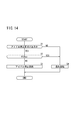
図14は、アイドル停止を実施するか否かの判断処理を示すフローチャートである。ステップS1において、制御部46は、アイドル停止の要求(を示す検知信号Sdの入力)があるか否かを判定し、アイドル停止の要求があれば(ステップS1のYES)、次に、R<Rth2であるか否かを判定する(ステップS2)。
FIG. 14 is a flowchart showing a process for determining whether or not to perform idle stop. In step S1, the
R<Rth2ではない、すなわち、R≧Rth2であり、地絡の発生を示す新たな検知信号Sdの入力がない場合には(ステップS2のNO)、地絡が発生していないと判断して、制御部46は、アイドル停止を実施する(ステップS3)。
When R <Rth2 is not satisfied, that is, when R ≧ Rth2, and there is no input of a new detection signal Sd indicating the occurrence of a ground fault (NO in step S2), it is determined that no ground fault has occurred. The
一方、ステップS1においてアイドル停止の要求がない場合(ステップS1のNO)や、ステップS2において、地絡の発生を示す新たな検知信号Sdが入力されて、R<Rth2であることが判明した場合(ステップS2のYES)に、制御部46は、通常運転を実施する(アイドル停止への移行を禁止するか、あるいは、アイドル停止を解除して通常運転への移行を行う)(ステップS4)。
On the other hand, when there is no idle stop request in step S1 (NO in step S1), or in step S2, a new detection signal Sd indicating the occurrence of a ground fault is input, and it is found that R <Rth2. (YES in step S2), the
以上説明したように、この実施形態では、絶縁抵抗Rがアイドル停止禁止閾値Rth2よりも低ければ(R<Rth2)、アイドル停止を禁止するので、正確且つ速やかに地絡を検出することができる。この場合、通常運転からアイドル停止への移行を禁止するか、あるいは、アイドル停止を解除して、通常運転に移行することにより、地絡が発生している場合には、該地絡を確実に検出することが可能となり、一方で、地絡が発生していない場合には、該地絡が誤検出されることを確実に防止することができる。 As described above, in this embodiment, when the insulation resistance R is lower than the idle stop prohibition threshold Rth2 (R <Rth2), the idle stop is prohibited, so that the ground fault can be detected accurately and promptly. In this case, if a ground fault has occurred by prohibiting the transition from the normal operation to the idle stop or canceling the idle stop and shifting to the normal operation, the ground fault is surely prevented. On the other hand, when a ground fault does not occur, it is possible to reliably prevent the ground fault from being erroneously detected.
また、地絡検知部64は、コンデンサ62の第1充電電圧Vc1及び第2充電電圧Vc2の比率に基づいて絶縁抵抗Rを算出し、算出した絶縁抵抗Rと地絡確定閾値Rth1及びアイドル停止禁止閾値Rth2との比較に基づいて、地絡の発生やアイドル停止の禁止の要求を検知信号Sdとして制御部46に出力する。これにより、地絡を精度よく検出することができる。
In addition, the ground
また、図1〜図3の回路図に示すように、地絡センサ26は、出力ライン14a、14b間のどの位置に配置してもよいので、燃料電池12とインバータ16との間の地絡の発生をより確実に検出することができる。
Also, as shown in the circuit diagrams of FIGS. 1 to 3, the
なお、この実施形態は、上記の説明に限定されるものではなく、この明細書及び図面の記載内容に基づき、種々の構成を採り得ることは勿論である。 Note that this embodiment is not limited to the above description, and it is needless to say that various configurations can be adopted based on the description in the specification and the drawings.
10…燃料電池車両 12…燃料電池
14a、14b、40a、40b、42a、42b…出力ライン
16…インバータ 18…モータ
26…地絡センサ 28…ダイオード
30、32…電圧センサ 34、44…コンタクタ
36、58…DC/DCコンバータ 38…バッテリ
46…制御部 50、52、60、70…抵抗器
54、56、68…地絡発生箇所 62…コンデンサ
64…地絡検知部 66a〜66c…スイッチ
DESCRIPTION OF
Claims (6)
前記燃料電池に駆動回路を介して接続され、車輪を回転させる電動機と、
前記燃料電池と前記駆動回路との間の地絡を検知する地絡検知装置と、
前記燃料電池、前記駆動回路及び前記電動機を制御する制御部と、
を備える電気車両において、
前記地絡検知装置は、前記地絡の発生箇所と接地との間の絶縁抵抗を算出し、算出した前記絶縁抵抗がアイドル停止禁止閾値よりも低ければ、前記絶縁抵抗が前記アイドル停止禁止閾値よりも低いことを示す検出結果を前記制御部に出力し、
前記制御部は、入力された前記検出結果に基づいて前記燃料電池のアイドル停止を禁止する
ことを特徴とする電気車両。 A fuel cell;
An electric motor connected to the fuel cell via a drive circuit and rotating a wheel;
A ground fault detection device for detecting a ground fault between the fuel cell and the drive circuit;
A control unit for controlling the fuel cell, the drive circuit and the electric motor;
In an electric vehicle comprising:
The ground fault detection device calculates an insulation resistance between the occurrence point of the ground fault and the ground, and if the calculated insulation resistance is lower than an idle stop prohibition threshold, the insulation resistance is lower than the idle stop prohibit threshold. Output a detection result indicating that the
The electric vehicle, wherein the control unit prohibits the fuel cell from being idled based on the input detection result.
前記制御部は、前記検出結果に基づいて、前記燃料電池が運転されている状態から、前記アイドル停止への移行を禁止する
ことを特徴とする電気車両。 The electric vehicle according to claim 1,
The control unit prohibits transition from the state in which the fuel cell is operated to the idle stop based on the detection result.
前記制御部は、前記検出結果に基づいて、前記アイドル停止を解除し、前記燃料電池の運転を開始する
ことを特徴とする電気車両。 The electric vehicle according to claim 1,
The control unit releases the idle stop and starts operation of the fuel cell based on the detection result.
前記地絡検知装置は、
前記燃料電池に並列に接続された、抵抗器及びコンデンサの直列回路と、
前記コンデンサの充電電圧を計測し、計測した前記充電電圧に基づいて前記地絡の発生を検知する地絡検知部と、
を有し、
前記地絡検知部は、
前記地絡が発生していないときの充電電圧(以下、第1充電電圧という。)を予め計測し、
前記地絡が発生したときの充電電圧(以下、第2充電電圧という。)を計測し、
前記第1充電電圧と前記第2充電電圧との比率に基づいて前記絶縁抵抗を算出し、算出した前記絶縁抵抗が前記アイドル停止禁止閾値よりも低い場合に、前記検出結果を前記制御部に出力し、
前記アイドル停止禁止閾値より低く設定された地絡確定閾値よりも前記絶縁抵抗が低い場合に、前記地絡の発生を前記制御部に通知する
ことを特徴とする電気車両。 The electric vehicle according to any one of claims 1 to 3,
The ground fault detection device is
A series circuit of a resistor and a capacitor connected in parallel to the fuel cell;
A ground fault detector that measures the charging voltage of the capacitor and detects the occurrence of the ground fault based on the measured charging voltage;
Have
The ground fault detector is
A charging voltage when the ground fault has not occurred (hereinafter referred to as a first charging voltage) is measured in advance,
Measure the charging voltage (hereinafter referred to as the second charging voltage) when the ground fault occurs,
The insulation resistance is calculated based on a ratio between the first charging voltage and the second charging voltage, and when the calculated insulation resistance is lower than the idle stop prohibiting threshold, the detection result is output to the control unit. And
The electric vehicle characterized by notifying the controller of the occurrence of the ground fault when the insulation resistance is lower than a ground fault determination threshold set lower than the idle stop prohibition threshold.
前記燃料電池と前記駆動回路との間には、前記燃料電池から前記駆動回路を介して前記電動機に電力を供給するためのダイオードが配置され、
前記駆動回路には、前記制御部により制御されるDC/DCコンバータを介して蓄電装置が、前記ダイオード及び前記燃料電池に対して並列に接続され、
前記地絡検知装置は、前記燃料電池と前記ダイオードとの間に接続されるか、あるいは、前記ダイオードと前記駆動回路との間に接続される
ことを特徴とする電気車両。 The electric vehicle according to any one of claims 1 to 4,
Between the fuel cell and the drive circuit, a diode for supplying electric power from the fuel cell to the electric motor via the drive circuit is disposed,
In the drive circuit, a power storage device is connected in parallel to the diode and the fuel cell via a DC / DC converter controlled by the controller.
The electric vehicle characterized in that the ground fault detection device is connected between the fuel cell and the diode, or connected between the diode and the drive circuit.
前記地絡の発生箇所と接地との間の絶縁抵抗を算出し、算出した前記絶縁抵抗がアイドル停止禁止閾値よりも低ければ、前記燃料電池のアイドル停止を禁止する
ことを特徴とする電気車両での地絡検出方法。 In an electric vehicle in which an electric motor that rotates a wheel is connected to a fuel cell via a drive circuit, when detecting a ground fault between the fuel cell and the drive circuit,
An electric vehicle that calculates an insulation resistance between the occurrence point of the ground fault and grounding, and prohibits idle stop of the fuel cell if the calculated insulation resistance is lower than an idle stop prohibition threshold. Ground fault detection method.
Priority Applications (1)
| Application Number | Priority Date | Filing Date | Title |
|---|---|---|---|
| JP2008160156A JP5207843B2 (en) | 2008-06-19 | 2008-06-19 | Electric vehicle and ground fault detection method in electric vehicle |
Applications Claiming Priority (1)
| Application Number | Priority Date | Filing Date | Title |
|---|---|---|---|
| JP2008160156A JP5207843B2 (en) | 2008-06-19 | 2008-06-19 | Electric vehicle and ground fault detection method in electric vehicle |
Publications (3)
| Publication Number | Publication Date |
|---|---|
| JP2010004631A true JP2010004631A (en) | 2010-01-07 |
| JP2010004631A5 JP2010004631A5 (en) | 2010-11-18 |
| JP5207843B2 JP5207843B2 (en) | 2013-06-12 |
Family
ID=41585866
Family Applications (1)
| Application Number | Title | Priority Date | Filing Date |
|---|---|---|---|
| JP2008160156A Expired - Fee Related JP5207843B2 (en) | 2008-06-19 | 2008-06-19 | Electric vehicle and ground fault detection method in electric vehicle |
Country Status (1)
| Country | Link |
|---|---|
| JP (1) | JP5207843B2 (en) |
Cited By (3)
| Publication number | Priority date | Publication date | Assignee | Title |
|---|---|---|---|---|
| KR20170119831A (en) * | 2016-04-20 | 2017-10-30 | 현대자동차주식회사 | Fuel cell vehicle and insulation resistance measuring method thereof |
| CN111902310A (en) * | 2018-04-06 | 2020-11-06 | 奥迪股份公司 | High-voltage system for determining insulation failure of fuel cell vehicle |
| CN114379369A (en) * | 2022-01-29 | 2022-04-22 | 重庆长安新能源汽车科技有限公司 | Method and system for judging electric vehicle fault authenticity based on national standard data and vehicle |
Citations (6)
| Publication number | Priority date | Publication date | Assignee | Title |
|---|---|---|---|---|
| JPH0215569A (en) * | 1988-07-04 | 1990-01-19 | Fuji Electric Co Ltd | Grounding detection circuit of fuel cell |
| JP2004170103A (en) * | 2002-11-18 | 2004-06-17 | Yazaki Corp | Insulation detector for non-grounded power supply |
| JP2005348483A (en) * | 2004-06-01 | 2005-12-15 | Nissan Motor Co Ltd | Earth detector for fuel battery vehicle |
| JP2006134647A (en) * | 2004-11-04 | 2006-05-25 | Nissan Motor Co Ltd | Fuel cell system |
| JP2007300753A (en) * | 2006-05-01 | 2007-11-15 | Nissan Motor Co Ltd | System for detecting insulation resistance |
| JP2008004482A (en) * | 2006-06-26 | 2008-01-10 | Nissan Motor Co Ltd | Fuel cell system |
-
2008
- 2008-06-19 JP JP2008160156A patent/JP5207843B2/en not_active Expired - Fee Related
Patent Citations (6)
| Publication number | Priority date | Publication date | Assignee | Title |
|---|---|---|---|---|
| JPH0215569A (en) * | 1988-07-04 | 1990-01-19 | Fuji Electric Co Ltd | Grounding detection circuit of fuel cell |
| JP2004170103A (en) * | 2002-11-18 | 2004-06-17 | Yazaki Corp | Insulation detector for non-grounded power supply |
| JP2005348483A (en) * | 2004-06-01 | 2005-12-15 | Nissan Motor Co Ltd | Earth detector for fuel battery vehicle |
| JP2006134647A (en) * | 2004-11-04 | 2006-05-25 | Nissan Motor Co Ltd | Fuel cell system |
| JP2007300753A (en) * | 2006-05-01 | 2007-11-15 | Nissan Motor Co Ltd | System for detecting insulation resistance |
| JP2008004482A (en) * | 2006-06-26 | 2008-01-10 | Nissan Motor Co Ltd | Fuel cell system |
Cited By (5)
| Publication number | Priority date | Publication date | Assignee | Title |
|---|---|---|---|---|
| KR20170119831A (en) * | 2016-04-20 | 2017-10-30 | 현대자동차주식회사 | Fuel cell vehicle and insulation resistance measuring method thereof |
| KR101869914B1 (en) * | 2016-04-20 | 2018-07-20 | 현대자동차주식회사 | Fuel cell vehicle and insulation resistance measuring method thereof |
| CN111902310A (en) * | 2018-04-06 | 2020-11-06 | 奥迪股份公司 | High-voltage system for determining insulation failure of fuel cell vehicle |
| US20210362624A1 (en) * | 2018-04-06 | 2021-11-25 | Audi Ag | High-voltage system for a fuel-cell vehicle for determining an insulation fault |
| CN114379369A (en) * | 2022-01-29 | 2022-04-22 | 重庆长安新能源汽车科技有限公司 | Method and system for judging electric vehicle fault authenticity based on national standard data and vehicle |
Also Published As
| Publication number | Publication date |
|---|---|
| JP5207843B2 (en) | 2013-06-12 |
Similar Documents
| Publication | Publication Date | Title |
|---|---|---|
| CN107428254B (en) | Power supply device for vehicle | |
| JP6174876B2 (en) | Dual power load drive system and fuel cell vehicle | |
| US20120020124A1 (en) | Apparatus for detecting short-circuit of output diode in converter | |
| US20170125995A1 (en) | Electricity storage system | |
| JP2010271267A (en) | Battery monitoring device | |
| JP5207843B2 (en) | Electric vehicle and ground fault detection method in electric vehicle | |
| JP2006020380A (en) | Power supply for vehicle | |
| JP6729714B2 (en) | Short circuit detector | |
| JP2004180395A (en) | Disconnection detector for voltage detection line of capacitor device | |
| JP2010148318A (en) | Dc/dc converter system | |
| JP2012243660A (en) | Electric vehicle control device | |
| JP4875640B2 (en) | Vehicle control device, electric vehicle, and failure detection method for vehicle control device | |
| JP2014155327A (en) | On-vehicle power supply device | |
| JP2015061505A (en) | Power storage system | |
| JP5978143B2 (en) | Battery system | |
| JP2014048281A (en) | Electric power unit and failure detection circuit | |
| JP2016067077A (en) | Electric power storage system | |
| KR20160043736A (en) | Power supply aparatus for electric vehicle and power supply method using it | |
| JP6647839B2 (en) | Energy storage system | |
| JP2015116051A (en) | Power supply control device | |
| JP5978144B2 (en) | Battery system | |
| JP6648217B2 (en) | Switch unit and battery device | |
| JP2010218953A (en) | Fuel cell system | |
| JP2011015537A (en) | Fuel cell vehicle | |
| JP6009969B2 (en) | Power supply |
Legal Events
| Date | Code | Title | Description |
|---|---|---|---|
| A521 | Written amendment |
Free format text: JAPANESE INTERMEDIATE CODE: A523 Effective date: 20101001 |
|
| A621 | Written request for application examination |
Free format text: JAPANESE INTERMEDIATE CODE: A621 Effective date: 20101001 |
|
| A977 | Report on retrieval |
Free format text: JAPANESE INTERMEDIATE CODE: A971007 Effective date: 20111124 |
|
| A131 | Notification of reasons for refusal |
Free format text: JAPANESE INTERMEDIATE CODE: A131 Effective date: 20111129 |
|
| A521 | Written amendment |
Free format text: JAPANESE INTERMEDIATE CODE: A523 Effective date: 20120130 |
|
| A131 | Notification of reasons for refusal |
Free format text: JAPANESE INTERMEDIATE CODE: A131 Effective date: 20120731 |
|
| A521 | Written amendment |
Free format text: JAPANESE INTERMEDIATE CODE: A523 Effective date: 20120926 |
|
| TRDD | Decision of grant or rejection written | ||
| A01 | Written decision to grant a patent or to grant a registration (utility model) |
Free format text: JAPANESE INTERMEDIATE CODE: A01 Effective date: 20130122 |
|
| A61 | First payment of annual fees (during grant procedure) |
Free format text: JAPANESE INTERMEDIATE CODE: A61 Effective date: 20130219 |
|
| FPAY | Renewal fee payment (event date is renewal date of database) |
Free format text: PAYMENT UNTIL: 20160301 Year of fee payment: 3 |
|
| R150 | Certificate of patent or registration of utility model |
Free format text: JAPANESE INTERMEDIATE CODE: R150 |
|
| LAPS | Cancellation because of no payment of annual fees |