JP2010004370A - Imaging device and image blurring correction method, and program - Google Patents
Imaging device and image blurring correction method, and program Download PDFInfo
- Publication number
- JP2010004370A JP2010004370A JP2008162101A JP2008162101A JP2010004370A JP 2010004370 A JP2010004370 A JP 2010004370A JP 2008162101 A JP2008162101 A JP 2008162101A JP 2008162101 A JP2008162101 A JP 2008162101A JP 2010004370 A JP2010004370 A JP 2010004370A
- Authority
- JP
- Japan
- Prior art keywords
- correction
- image
- image blur
- optical
- correction amount
- Prior art date
- Legal status (The legal status is an assumption and is not a legal conclusion. Google has not performed a legal analysis and makes no representation as to the accuracy of the status listed.)
- Granted
Links
Images


Classifications
-
- G—PHYSICS
- G03—PHOTOGRAPHY; CINEMATOGRAPHY; ANALOGOUS TECHNIQUES USING WAVES OTHER THAN OPTICAL WAVES; ELECTROGRAPHY; HOLOGRAPHY
- G03B—APPARATUS OR ARRANGEMENTS FOR TAKING PHOTOGRAPHS OR FOR PROJECTING OR VIEWING THEM; APPARATUS OR ARRANGEMENTS EMPLOYING ANALOGOUS TECHNIQUES USING WAVES OTHER THAN OPTICAL WAVES; ACCESSORIES THEREFOR
- G03B5/00—Adjustment of optical system relative to image or object surface other than for focusing
-
- H—ELECTRICITY
- H04—ELECTRIC COMMUNICATION TECHNIQUE
- H04N—PICTORIAL COMMUNICATION, e.g. TELEVISION
- H04N23/00—Cameras or camera modules comprising electronic image sensors; Control thereof
- H04N23/60—Control of cameras or camera modules
- H04N23/68—Control of cameras or camera modules for stable pick-up of the scene, e.g. compensating for camera body vibrations
- H04N23/681—Motion detection
- H04N23/6812—Motion detection based on additional sensors, e.g. acceleration sensors
-
- H—ELECTRICITY
- H04—ELECTRIC COMMUNICATION TECHNIQUE
- H04N—PICTORIAL COMMUNICATION, e.g. TELEVISION
- H04N23/00—Cameras or camera modules comprising electronic image sensors; Control thereof
- H04N23/60—Control of cameras or camera modules
- H04N23/68—Control of cameras or camera modules for stable pick-up of the scene, e.g. compensating for camera body vibrations
- H04N23/682—Vibration or motion blur correction
- H04N23/685—Vibration or motion blur correction performed by mechanical compensation
- H04N23/687—Vibration or motion blur correction performed by mechanical compensation by shifting the lens or sensor position
-
- G—PHYSICS
- G03—PHOTOGRAPHY; CINEMATOGRAPHY; ANALOGOUS TECHNIQUES USING WAVES OTHER THAN OPTICAL WAVES; ELECTROGRAPHY; HOLOGRAPHY
- G03B—APPARATUS OR ARRANGEMENTS FOR TAKING PHOTOGRAPHS OR FOR PROJECTING OR VIEWING THEM; APPARATUS OR ARRANGEMENTS EMPLOYING ANALOGOUS TECHNIQUES USING WAVES OTHER THAN OPTICAL WAVES; ACCESSORIES THEREFOR
- G03B2217/00—Details of cameras or camera bodies; Accessories therefor
- G03B2217/005—Blur detection
Abstract
Description
本発明は、振動等によって生じた像振れを効率的に処理することができる撮像装置、及び像振れ補正方法並びにプログラムに関する。 The present invention relates to an imaging apparatus, an image blur correction method, and a program that can efficiently process image blur caused by vibration or the like.
デジタルカメラ等の撮像装置で撮像された画像は、画像撮像時にカメラ本体を保持する、例えばユーザの手が揺れることにより被写体像に振れ、いわゆる手振れが生じる場合がある。このため、デジタルカメラには、ユーザの手の動きを含め、カメラ本体に加えられた振動によって撮像画像に現れる被写体像の振れ(以下、「像振れ」という。)を補正する補正機能が組み込まれている。 An image captured by an image capturing apparatus such as a digital camera may hold a camera body at the time of image capturing. For example, when a user's hand shakes, the image may be shaken in a subject image, and so-called camera shake may occur. For this reason, the digital camera has a built-in correction function that corrects shake of a subject image (hereinafter referred to as “image shake”) that appears in a captured image due to vibration applied to the camera body, including movement of the user's hand. ing.
像振れ補正処理としては、従来より光学的像振れ補正処理や、電子的像振れ補正処理が知られており、これらの処理によって像振れをキャンセルすることで実現している。 As the image blur correction process, an optical image blur correction process and an electronic image blur correction process are conventionally known, and these processes are realized by canceling the image blur.
光学式像振れ補正処理は、角加速度センサなどでカメラ本体に加えられた振動を検出して、この検出結果に応じて被写体像を形成する撮像光学系内部に設けられたプリズムを回転させ、この撮像光学系の光軸方向を変化させることによって撮像素子の受光面に結像される像を移動して像振れを補正する処理である。また、電子式像振れ補正は、撮像画像に画像処理を施して、擬似的に像振れを補正する処理である。 The optical image shake correction processing detects vibration applied to the camera body with an angular acceleration sensor or the like, and rotates a prism provided inside the imaging optical system that forms a subject image according to the detection result. This is a process of correcting the image blur by moving the image formed on the light receiving surface of the image sensor by changing the optical axis direction of the imaging optical system. The electronic image blur correction is a process of performing image processing on a captured image and correcting image blur in a pseudo manner.
ところで、光学的像振れ補正処理または電子的像振れ補正処理のどちらかを採用して像振れ補正処理を施していた従来の撮像装置においては、検出した像振れ信号のうち、比較的振幅の小さな像振れに対しては、十分な補正余裕を確保して補正することが可能であった。しかしながら、例えば車等の移動体の中から撮像された場合に生じる振幅の大きな像振れに対しては、補正余裕を十分に確保することができない場合があり、効率的に像振れ補正を施すことができない場合があった。 By the way, in a conventional imaging apparatus that has applied image blur correction processing using either optical image blur correction processing or electronic image blur correction processing, the detected image blur signal has a relatively small amplitude. Image blur can be corrected with a sufficient correction margin. However, there may be cases where a sufficient correction margin cannot be secured for image blur with a large amplitude that occurs when an image is taken from a moving body such as a car, and image blur correction is performed efficiently. There was a case that could not be.
このような振幅の大きな像振れに対して補正処理を行うために、従来の撮像装置では、以下のようにして補正余裕を確保していた。すなわち、光学式像振れ補正を行う場合には、補正角を広げることによって補正余裕を確保し、一方電子式像振れ補正を行う場合には、補正余剰領域を広げることによって補正余裕を確保していた。 In order to perform correction processing for such an image shake having a large amplitude, the conventional imaging apparatus has secured a correction margin as follows. That is, when optical image blur correction is performed, a correction margin is secured by widening the correction angle, while when electronic image blur correction is performed, a correction margin is secured by widening the correction surplus area. It was.
しかしながら、光学式像振れ補正の場合、補正角を広げるようにすることで、レンズやアクチュエーターが大型化してしまい、それに伴って撮像装置自体が重量化し、さらに大型化したレンズをシフト駆動するために多くの電力を消費し、レンズを大きく振ることによって光学性能が劣化する等の種々の問題を発生させていた。 However, in the case of optical image blur correction, widening the correction angle increases the size of the lens and the actuator, and accordingly, the imaging device itself becomes heavier, so that the larger lens is shifted and driven. A lot of power was consumed, and various problems such as optical performance deteriorated by shaking the lens greatly occurred.
また、電子式像振れ補正の場合では、補正余剰領域を広げることによって、実効領域が縮小し、それに伴って画像が劣化してしまい、また画像更新周期が長いことによって補正性能が劣化するといった問題を生じさせていた。 In addition, in the case of electronic image blur correction, the effective area is reduced by expanding the correction surplus area, the image is deteriorated accordingly, and the correction performance is deteriorated due to a long image update period. Was caused.
これらの問題に対して、特許文献1の技術が提案されている。この特許文献1の技術は、光学式振れ補正と電子式振れ補正とを併用することによって、画質劣化のない振れ補正を実現させようとするものである。
The technique of
しかしながら、特許文献1に記載された技術では、光学式振れ補正は角速度センサによる振れ検出に基づいて処理され、一方で電子式振れ補正は画像動き検出回路による検出に基づいて処理され、それぞれの補正手段は撮像装置内において独立して存在しているとともに、その振れ検出機構もそれぞれ独立して設けられているので、双方の処理の整合性を取った制御を行うことができない。このように、各処理が独立して行われる場合には、電力消費が増大するとともに、効率的な振れ補正を実現することができないという問題があった。
However, in the technique described in
そこで、本発明は、このような実情に鑑みて提案されたものであり、振幅の大きな像振れに対しても十分な補正余裕を確保することを可能にし、効率的な像振れ補正を行うことができる撮像装置、及び像振れ補正方法並びにプログラムを提供することを目的とする。 Therefore, the present invention has been proposed in view of such a situation, and it is possible to secure a sufficient correction margin even for an image blur having a large amplitude, and to perform an efficient image blur correction. It is an object of the present invention to provide an image pickup apparatus, an image blur correction method, and a program that can perform the above-described processing.
上述した課題を解決するため、本発明における撮像装置は、被写体像を形成する撮像光学系と、上記撮像光学系によって形成される被写体像を光電変換した撮像画像を読み出す撮像素子と、動き検出センサを用いて像振れ信号を出力する像振れ検出部と、上記像振れ信号に基づいて、光学的補正量と電子的補正量とからなる像振れ補正量を算出する演算部と、上記撮像光学系の一部を構成する光学素子と上記撮像素子の少なくとも一方を移動させ、上記光学補正量に応じて、光学的に像振れを補正する光学像振れ補正部と、上記撮像素子により読み出された撮像画像の像振れを上記電子的補正量に基づく画像処理により電子的に補正する電子像振れ補正部とを備え、上記演算部は、上記像振れ信号を周波数帯域別に分離する分離部と、上記分離部にて分離された像振れ信号の高周波成分に基づいて、上記光学的補正量を算出する光学像振れ補正演算部と、上記分離部にて分離された像振れ信号の低周波成分に基づいて、上記電子的補正量を算出する電子像振れ補正演算部と備える。 In order to solve the above-described problems, an imaging apparatus according to the present invention includes an imaging optical system that forms a subject image, an imaging element that reads a captured image obtained by photoelectrically converting the subject image formed by the imaging optical system, and a motion detection sensor. An image shake detection unit that outputs an image shake signal using the image, an arithmetic unit that calculates an image shake correction amount composed of an optical correction amount and an electronic correction amount based on the image shake signal, and the imaging optical system An optical image blur correction unit that optically corrects an image blur according to the optical correction amount and at least one of the optical element that constitutes a part of the image sensor and the image sensor, and read by the image sensor An electronic image blur correction unit that electronically corrects image blur of the captured image by image processing based on the electronic correction amount, and the arithmetic unit separates the image blur signal by frequency band; and Min Based on the high-frequency component of the image blur signal separated by the optical unit, based on the optical image blur correction calculation unit that calculates the optical correction amount, and on the low-frequency component of the image blur signal separated by the separation unit And an electronic image shake correction calculating unit for calculating the electronic correction amount.
また、上述した課題を解決するため、本発明における像振れ補正方法は、センサを用いて検出された像振れ信号を高周波成分と低周波成分に分離する分離工程と、上記高周波成分に基づいて光学的補正量を算出する光学的補正量算出工程と、上記低周波成分に基づいて電子的補正量を算出する電子的補正量算出工程と、上記光学的補正量に基づいて、光学的に像振れ補正処理を行う光学的像振れ補正工程と、上記電子的補正量に基づいて、電子的に像振れ補正処理を行う電子的像振れ補正工程とを有する。 In order to solve the above-described problems, an image blur correction method according to the present invention includes a separation step of separating an image blur signal detected using a sensor into a high frequency component and a low frequency component, and optical based on the high frequency component. An optical correction amount calculating step for calculating an optical correction amount, an electronic correction amount calculating step for calculating an electronic correction amount based on the low-frequency component, and an optical image blur based on the optical correction amount. An optical image blur correction step for performing correction processing; and an electronic image blur correction step for electronically performing image blur correction processing based on the electronic correction amount.
また、本発明におけるプログラムは、センサを用いて検出された像振れ信号を高周波成分と低周波成分に分離する分離工程と、上記高周波成分に基づいて光学的補正量を算出する光学的補正量算出工程と、上記低周波成分に基づいて電子的補正量を算出する電子的補正量算出工程と、上記光学的補正量に基づいて、光学的に像振れ補正処理を行う光学的像振れ補正工程と、上記電子的補正量に基づいて、電子的に像振れ補正処理を行う電子的像振れ補正工程とからなる像振れ補正方法をコンピュータに実行させる。 The program according to the present invention includes a separation step of separating an image blur signal detected using a sensor into a high frequency component and a low frequency component, and an optical correction amount calculation that calculates an optical correction amount based on the high frequency component. A step, an electronic correction amount calculating step for calculating an electronic correction amount based on the low-frequency component, and an optical image blur correction step for optically performing image blur correction processing based on the optical correction amount. Based on the electronic correction amount, the computer is caused to execute an image blur correction method including an electronic image blur correction process for electronically performing an image blur correction process.
本発明に係る撮像装置によれば、検出した像振れ信号を周波数帯域別に分離し、光学像振れ補正処理と電子像振れ補正処理とによる補正処理を施すことを可能にしているので、振幅の大きな像振れに対しても十分な補正余裕を確保することができるとともに、振幅の小さな像振れに対しては光学像振れ補正処理を施すようにすることで、電力消費を最小限に抑え、画像劣化の少ない補正処理を施すことができる。 According to the imaging apparatus of the present invention, the detected image shake signal is separated by frequency band, and correction processing by optical image shake correction processing and electronic image shake correction processing can be performed. A sufficient correction margin can be secured for image blur, and optical image blur correction processing is applied to image blur with a small amplitude to minimize power consumption and image degradation. It is possible to perform a correction process with less.
以下、本実施の形態に係る撮像装置について、図面を参照にして詳細に説明する。 Hereinafter, the imaging apparatus according to the present embodiment will be described in detail with reference to the drawings.
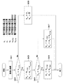
<システム構成>
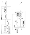
図1は、本実施の形態に係る撮像装置のシステム構成を示す図である。この図1に示すように、この撮像装置10は、被写体像を形成してその被写体像に応じた画像信号を読み出すレンズユニット100と、レンズユニット100から読み出された画像信号に対して画像処理を施す画像処理ユニット200と、画像データを記録する記録部300と、動きを検出するセンサを用いて像振れ信号を検出する像振れ検出部400と、像振れ検出部400より検出された像振れを補正するための補正量を算出する演算部500とを備えている。
<System configuration>
FIG. 1 is a diagram illustrating a system configuration of an imaging apparatus according to the present embodiment. As shown in FIG. 1, the
レンズユニット100は、複数の光学素子と撮像素子とからなり、被写体像を撮像素子103の受光面に形成する撮像光学系である。このレンズユニット100は、レンズ101と、像振れ補正するためのシフト防振レンズ102と、レンズ101において結像された被写体像を光電変換して電気信号として取り込むための撮像素子103と、シフト防振レンズ102を制御するためのレンズシフトドライバ104とから構成され、その撮像素子103は、例えば、CCD(Charge Coupled Device)イメージセンサやCMOS(Complementary Metal Oxide Semiconductor)イメージセンサ等の固体撮像素子により構成されている。このような構成を有するレンズユニット100においては、結像された被写体像がデジタル信号に変換されて画像処理ユニット200に出力される。
The
より具体的には、複数の光学素子からなるレンズ101は、被写体像を変倍可能に形成するズームレンズ群を有しており、被写体像を撮像素子103の受光面に形成していく。そして、撮像素子103は、レンズ101によって形成される被写体像を、その受光面上に配列した複数の画素で光電変換を行い、光電変換した電気信号をアナログ形式からデジタル形式に変換し、この変換したデジタル形式の撮像画像を画像処理ユニット200に供給する。
More specifically, the
このレンズユニット100において、後述する光学像振れ補正演算部503から出力された光学像振れ補正量に基づき、シフト防振レンズ102をレンズ101の光軸に対して直交する方向にシフトさせることで、装置に加えられた振動によって生じる像振れを光学的に補正する。なお、光学的な像振れ補正としては種々のものが知られており、例えば、撮像素子103の受光面をx方向及びy方向に移動させることで像振れを補正してもよい。また、シフト防振レンズ102の代わりにプリズムをレンズユニット100に設けて、このプリズムをx方向及びy方向を軸とした回転方向に移動することで像振れを補正するようにしてもよい。
In this
画像処理ユニット200は、レンズユニット100から出力されたデジタル画像信号に対して所定の画像処理を施す。この画像処理ユニット200は、画像処理部201と、像振れ補正部202とから構成されている。
The
画像処理部201は、レンズユニット100における撮像素子103から出力されたデジタル信号を処理するためのもので、デジタルゲインによる明るさ、色、ガンマなどの画像処理を施し、後述する記録部300における記憶形式や、図示しない表示部の表示形式に応じたデータ形式に変換して、処理したデジタル信号を電子像振れ補正部202に供給する。電子像振れ補正部202は、電子的な像振れ補正処理を行うためのブロックであり、後述する電子像振れ補正演算部504より指示された像振れ補正量に応じて画像処理による電子的な像振れ補正処理を施す。
The
なお、この画像処理ユニット200の説明において、画像処理部201によりデジタル信号に対して所定の画像処処理を施した後に、電子像振れ補正部202に画像処理したデジタル信号を供給する例を挙げて説明したが、これに限られるものではなく、電子像振れ補正部202において補正処理を施した後に、画像処理部201において所定の画像処理を施すようにしてもよい。
In the description of the
記録部300は、画像処理ユニット200から供給されるデジタル画像信号を記録する。また、記録部300は、記憶しているデジタル画像信号を、例えば後述する演算部500からの制御命令に従って、画像処理ユニット200に読み出す処理も行う。
The
像振れ検出部400は、動き検出センサを用いて撮像装置に加振された像振れ信号を検出し、その像振れ信号を後述する演算部500に出力する。具体的に、像振れ検出部400は、撮像装置本体の動きを検出するために、角速度センサなどのセンサにより実現される。例えば、角速度を検出するジャイロセンサによって実現される場合、ピッチング方向、ヨーイング方向、それぞれの方向に加えられた角速度のデータに基づく振動量を検出し、検出した振動量に基づく像振れ信号をそれぞれ演算部500に供給する。なお、この像振れ検出部400は、加速度センサを用いて、撮像装置本体の動きを検出するようにしてもよい。
The image
演算部500は、CPU(Central Processing Unit)等によって構成され、像振れ検出部400が検出した振動量に基づいて補正演算を行い、振れに伴う動きを補正するために像振れ補正量算出し、像振れ補正手段に対して補正量に関する指示を出力する。このような演算部500は、HPF501と、減算部502と、光学像振れ補正演算部503と、電子像振れ補正演算部504と、信号解析部505とから構成されている。
The
HPF501は、像振れ検出部400より出力された像振れ信号の高周波成分を抽出し、光学像振れ補正演算部503に出力する。
The
減算部502は、像振れ検出部400より出力された像振れ信号からHPF501によって出力された高周波成分を引き算することで、像振れ信号の低周波成分を抽出する。
The
光学像振れ補正演算部503は、HPF501の出力値に基づいて、像振れ補正量を演算し、レンズユニット100におけるレンズシフトドライバ104に対してその像振れ補正量を出力する。
The optical image blur
電子像振れ補正演算部504は、減算部502の出力値に基づいて、像振れ補正用に使用する余剰領域を用いて有効領域内において実行領域を移動させるための像振れ補正量を演算し、画像処理ユニットにおける像振れ補正部202に対して出力する。
Based on the output value of the
信号解析部505は、像振れ検出部400から出力された像振れ信号の特徴を解析し、レンズシフトドライバ104に対して指示する。具体的には、像振れ信号の振幅の大きさ等の振幅状態の確認を行い、例えば、大振幅であった場合には、レンズシフトドライバ104の電力を増やし、補正角を十分大きく確保するように制御することを可能にしている。このように像振れ信号の振幅の大きさを解析して、その像振れ信号の振幅状態に基づく光学補正処理を施すようにすることで、電力量等の制御を行い、消費電力量を低減させることができる。詳しくは後述する。
The
このような構成からなる本実施の形態に係る撮像装置10の各処理部は、以下のような動作周波数で動作させることができる。すなわち、像振れ検出部400の動作周波数は、像振れ信号の高周波成分よりも高い周波数以上でサンプリングを行い、これにより、精度高く像振れ信号を検出することを可能にする。また、HPF501のカットオフ周波数は、シフト防振レンズ102の可動範囲と像振れにおける周波数特性から、高周波成分の振幅がシフト防振レンズ102の可動範囲に収まる振幅の周波数に設定される。また、光学像振れ補正演算部503の動作周波数は、像振れ信号の高周波成分よりも高い周波数で動作する。さらに、電子像振れ補正演算部504の動作周波数は、補正周波数が画像更新周波数(NTSC(National TV Standards Committee)方式:60Hz、PAL(Phase Alternating Line)方式:50Hz)であり、露光中心に像振れ信号のサンプリングポイントを合致させるために、画像更新周波数以上で動作させる。
Each processing unit of the
具体的に、上記の動作周波数条件を満たす周波数例としては、例えば、像振れ検出部400は像振れ信号の周波数成分よりも十分高い4kHzで動作させ、HPF501のカットオフ周波数は高周波成分の振幅がシフト防振レンズ102の可動範囲に収まる周波数である2Hzで動作させる。また、光学像振れ補正演算部503は像振れ検出部400と同じ4kHzで動作させ、そして、電子像振れ補正演算部504は画像更新周波数よりも高く、露光中心のサンプリングポイントに合わすために必要な周波数である1kHzで動作させる。なお、この動作周波数条件は、一例であり、当然これに限られるものではない。
Specifically, as a frequency example satisfying the above operating frequency condition, for example, the image
このように、本実施の形態に係る撮像装置10においては、像振れ検出部400にて検出した像振れ信号を、演算部500において高周波成分と低周波成分とに分離し、分離した各周波数帯域の像振れ信号毎にそれぞれ補正演算して、像振れ補正処理を施すようにしている。具体的には、分離した像振れ信号のうち、高周波成分の像振れ信号に基づいて光学的補正量を算出し、算出した光学的補正量に応じて光学的に像振れを補正する。一方で、分離した像振れ信号のうち、低周波成分の像振れ信号に基づいて電子的補正量を算出し、算出した電子的補正量に応じて電子的に像振れを補正する。
As described above, in the
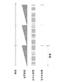
ここで、図2に、一般的に取得される、像振れ信号の周波数とその像振れ周波数の像振れ振幅との関係性についての一例を示す。また、図3に、像振れ信号とその周波数成分毎の波形を示す。 Here, FIG. 2 shows an example of the relationship between the frequency of the image shake signal and the image shake amplitude of the image shake frequency that are generally acquired. FIG. 3 shows an image shake signal and a waveform for each frequency component.
この図2及び図3から判るように、一般的に、像振れ信号のうちの高周波成分の振幅は小さく、低周波成分の振幅は大きくなっている。すなわち、振幅の大きな像振れ信号は低周波帯域に偏っていることが判る。 As can be seen from FIGS. 2 and 3, generally, the amplitude of the high frequency component of the image blur signal is small and the amplitude of the low frequency component is large. That is, it can be seen that the image shake signal having a large amplitude is biased toward the low frequency band.
上述したように、例えば、光学像振れ補正によって全ての周波数帯域に亘る像振れをキャンセルさせようとする場合、補正角を広げて、振幅の大きな像振れにも対応可能なように補正余裕を確保することによって対応させることができる。しかしながら、この場合には、レンズやアクチュエーターが大型化し、それに伴って重量が増加するとともに、レンズを駆動するための消費電力が増大する。また、レンズを大きく振ることによって光学性能が劣化等の種々の問題が発生し、効率的な像振れ補正を実現することが難しくなる。 As described above, for example, when trying to cancel image blur over all frequency bands by optical image blur correction, the correction angle is widened to ensure a correction margin so that image blur with a large amplitude can be handled. It is possible to make it correspond by doing. However, in this case, the lens and the actuator are increased in size, and accordingly, the weight is increased and the power consumption for driving the lens is increased. In addition, when the lens is shaken greatly, various problems such as deterioration of optical performance occur, and it becomes difficult to realize efficient image blur correction.
一方で、電子像振れ補正によって全ての周波数帯域にわたる像振れをキャンセルさせようとする場合、補正余剰領域を広げて、振幅の大きな像振れにも対応可能なように補正余裕を確保することによって対応させることができる。しかしながら、この場合では、実効領域の縮小による画像劣化、画像更新周期が長いことによる補正性能の劣化等により、効果的な像振れ補正を実現させることがやはり難しい。 On the other hand, when trying to cancel image blur over all frequency bands by electronic image blur correction, it is possible to widen the correction surplus area and secure a correction margin so that it can cope with image blur with large amplitude. Can be made. However, in this case, it is still difficult to realize effective image blur correction due to image degradation due to reduction of the effective area, degradation of correction performance due to a long image update period, and the like.
そこで、本実施の形態に係る撮像装置10においては、上述したように、装置に加えられた動きや振動によって生じた像振れに対して、光学像振れ補正処理と電子像振れ補正処理を施すようにしている。これにより、光学補正処理または電子補正処理の単独で像振れ補正処理を行うよりも、それぞれ少ない補正余裕を確保するだけで、大振幅の像振れに対しても十分な補正余裕を確保することができる。そして、従来生じていた装置の大型化や画像劣化といった問題をなくすことが可能となる。
Therefore, in the
さらに、本実施の形態に係る撮像装置10においては、像振れ信号に対して光学像振れ補正処理と電子像振れ補正処理とを施すにあたり、像振れ信号の周波数帯域別に補正方式を区別するようにしている。すなわち、像振れ検出部400において検出した像振れ信号を高周波成分と低周波成分とに分離し、高周波数成分の像振れ信号に対しては算出した光学像振れ補正量に応じて光学像振れ補正処理を施し、低周波成分の像振れ信号に対しては算出した電子像振れ補正量に応じて電子像振れ補正処理を施すようにしている。
Further, in the
高周波成分からなる像振れ信号を光学像振れ補正によって処理する理由としては、高周波に対する像振れ補正特性の優位性にある。すなわち、電子像振れ補正処理を実行する電子像振れ補正部202は、その放送方式(NTSC方式またはPAL方式等)に強く依存するために、画像更新周期(NTSC方式では60Hz、PAL方式では50Hz)より高い周波数の補正が不可能となる。それに対して、レンズシフトドライバ104は、その放送方式に依存しないため、高周波で補正駆動させることが可能となっている。したがって、このことから、像振れ信号のうち、高周波帯域にあるものに対しては光学像振れ補正処理を施し、低周波帯域にあるものに対しては電子像振れ補正処理を施すようにしている。
The reason why an image blur signal composed of a high frequency component is processed by optical image blur correction lies in the superiority of image blur correction characteristics with respect to high frequency. That is, the electronic image
このように、像振れ信号を高周波成分と低周波成分とに分離し、像振れ信号の周波数特性に合わせて補正処理を施すことにより、周波数特性に合った像振れ補正処理を施すことが可能となり、効果的な像振れ補正を実現することができる。 As described above, the image blur signal is separated into a high-frequency component and a low-frequency component, and correction processing is performed according to the frequency characteristics of the image blur signal, so that it is possible to perform image blur correction processing that matches the frequency characteristics. Effective image blur correction can be realized.
また、詳しくは後述するが、撮像装置内に光学像振れ補正処理と電子像振れ補正処理との両方が可能となるようにした場合においても、光学像振れ補正部と電子像振れ補正部とを、その装置内において独立して存在させている場合、双方の補正処理の整合性をとるのが難しく、所望とする像振れ補正結果が得られないという問題が発生する。 Further, as will be described in detail later, even when both the optical image shake correction process and the electronic image shake correction process are enabled in the imaging apparatus, the optical image shake correction unit and the electronic image shake correction unit are provided. If they exist independently in the apparatus, it is difficult to achieve consistency between the two correction processes, resulting in a problem that a desired image blur correction result cannot be obtained.
しかしながら、本実施の形態に係る撮像装置10においては、像振れ検出部400からの像振れ信号を、像振れ検出部と像振れ演算部とが一元管理可能なように構成された演算部500に出力して、各補正処理量を算出するようにしているので、光学像振れ補正部と電子像振れ補正部の双方の整合性をとることが容易になり、所望の像振れ補正結果を得易くすることができる。
However, in the
以下では、さらに詳細に上記構成を有する撮像装置10の像振れ補正処理について説明をしていく。
Hereinafter, image blur correction processing of the
<光学像振れ補正処理>
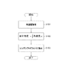
まず、本実施の形態に係る撮像装置10における光学像振れ補正処理について図4を参照にして説明する。図4は、光学像振れ補正量演算の処理を説明するための処理フローである。
<Optical image shake correction processing>
First, optical image shake correction processing in the
本実施の形態に係る撮像装置10は、上述したように、像振れ検出部400において検出された像振れ信号を演算部500に出力し、その像振れ信号をHPF501に通過させて高周波成分の像振れ信号を抽出する。そして、抽出した高周波成分の像振れ信号は光学像振れ補正演算部503に出力され、この光学像振れ補正演算部503は、まずステップS101において、抽出した高周波成分からなる像振れ信号から角速度を取得する。
As described above, the
具体的には、例えば、像振れ検出部400においてジャイロセンサ等の角速度センサを用いた場合、この角速度センサは撮像装置本体のx方向の移動を検出するx方向移動検出センサと、y方向の移動を検出するy方向移動検出センサとからなっており、これらの移動検出センサによって、x方向及びy方向の位置移動量が検出され、光学像振れ補正演算部503は、この位置移動量から角速度を取得する。なお、像振れ検出部400に用いられる像振れ検出センサは、角速度センサには限られず、例えば3軸の加速度センサを用いるようにしてもよい。
Specifically, for example, when an angular velocity sensor such as a gyro sensor is used in the image
このようにして、ステップS101にて抽出した高周波成分からなる像振れ信号の角速度を取得すると、光学像振れ補正演算部503は、次にステップS102において、下記に示す式のように、その取得した角速度を時間積分することによって補正角度を算出する。
補正角度=∫角速度dt
In this way, when the angular velocity of the image blur signal composed of the high-frequency component extracted in step S101 is acquired, the optical image blur
Correction angle = Depression speed dt
そして、ステップS102にて補正角度を算出すると、次に、ステップS103において、算出した補正角度の情報を、レンズユニット100におけるレンズシフトドライバ104に対して供給することで補正角を指示する。
When the correction angle is calculated in step S102, information on the calculated correction angle is supplied to the
このような光学像振れ補正処理のフローにより、HPF501より出力された像振れの高周波成分は、光学像振れ補正演算部503により角速度から補正角度が決定され、その補正角度をレンズシフトドライバ104に対して指示し、その結果、撮像素子103は像振れの高周波成分が打ち消された状態で露光されるようになる。
According to the flow of the optical image blur correction process, the high-frequency component of the image blur output from the
具体的には、撮像装置10では、上述のようにして、装置本体に加えられた振動を検出し、この検出結果に応じて、レンズシフトドライバ104の制御のもとにシフト防振レンズ102をレンズ101の光軸に対して直交する方向に移動させることで、この装置に加えられた振動によって生じる像振れを光学的に補正する。
Specifically, the
すなわち、撮像装置10は、レンズユニット100の光軸を変化させ撮像素子103の受光面上で被写体像の移動がなくなるように制御する。
That is, the
なお、上述した光学像振れ補正処理に関わらず、撮像装置10は、次のような補正処理を行うようにしてもよい。すなわち、撮像装置10は、撮像素子103の受光面をx方向及びy方向に移動させることで像振れを補正してもよい。このように撮像素子103を移動させて像振れを補正する場合には、レンズユニット100の光軸を固定した状態で撮像素子103の受光面上で被写体像の移動がなくなるように制御する。また、撮像装置10は、シフト防振レンズ102の代わりにプリズムをレンズユニット100に設けて、このプリズムをx方向及びy方向を軸とした回転方向に移動することで像振れを補正するようにしてもよい。同様にして撮像装置10は、撮像素子103をx方向及びy方向を軸とした回転方向に移動することで像振れを光学的に補正するようにしてもよい。
Regardless of the optical image shake correction process described above, the
<光学補正角範囲の制御>
ところで、上述したように、本実施の形態に係る撮像装置10は、HPF501抽出した高周波帯域にある像振れ信号に対しては光学像振れ補正処理を施すようにしているが、その高周波帯域に存在する像振れ信号のうちでも、振幅の大小に違いがあり、その振幅の大きさによって適切なレンズユニット100の制御を行うことが好ましい。それにより、必要最小限の電力量で光学像振れ補正処理を施すことを可能にし、電子消費を抑えることができる。そこで、本実施の形態に係る撮像装置10においては、演算部500に信号解析部505を備えており、撮像装置10に生じた像振れ信号の振幅の大小等に関する特徴を解析し、その解析情報を用いて補正角範囲を決定するようにしている。以下では、詳細に、この光学補正角範囲の制御機構について説明する。
<Control of optical correction angle range>
Incidentally, as described above, the
図5は、本実施の形態に係る撮像装置10の、光学像振れ補正処理の補正角の制御について説明するための制御フローである。
FIG. 5 is a control flow for explaining control of the correction angle of the optical image shake correction process of the
本実施の形態に係る撮像装置10は、上述したように、像振れ検出部400において、撮像装置10に加えられた振動によって生じた像振れを検出すると、その像振れ信号を演算部500に出力し、HPF501を通過させて像振れ信号を高周波成分と低周波成分に分離して周波数帯域毎に補正量を算出するが、このとき、本実施の形態に係る撮像装置10は、まずステップS201において、検出した像振れ信号を信号解析部505にも出力し、その信号解析部505にて像振れ信号の解析を行う。
As described above, when image
具体的には、例えば、高速フーリエ変換(FFT:Fast Fourier Transform)等の周波数解析を行い、例えば、高周波成分が高い場合には歩行中の状態や車等の移動体中に居る状態であると判断し、また低周波成分が高い場合にはパンやチルト状態であると判断する。 Specifically, for example, frequency analysis such as Fast Fourier Transform (FFT) is performed. For example, when the high frequency component is high, it is in a walking state or in a moving body such as a car. If the low frequency component is high, it is determined that the camera is in a pan or tilt state.
このように、まず信号解析部505において、検出された像振れ信号から、その像振れ信号の状態を解析すると、次に、ステップS202において、その解析した状態に応じて、像振れの振幅が大きいか否かを判断する。
As described above, when the
具体的には、例えば、歩行中状態であると判断された場合には、検出した像振れの振幅が大きい状態(大振幅状態)であると判断する。そして、このステップS202において、大振幅状態であると判断されると(ステップS202にてYES:Yの場合)、ステップS203に進む。一方で、ステップS202において、大振幅状態ではないと判断されると(ステップS202にてNO:Nの場合)、ステップS204に進む。 Specifically, for example, when it is determined that the vehicle is in a walking state, it is determined that the detected image shake has a large amplitude (large amplitude state). If it is determined in step S202 that the state is a large amplitude state (YES in step S202: Y), the process proceeds to step S203. On the other hand, if it is determined in step S202 that the state is not a large amplitude state (NO in step S202), the process proceeds to step S204.
ステップS202にて、大振幅状態にあると判断されると、次に、ステップS203において、検出された大振幅の像振れ信号に対応した光学像振れ補正処理を可能にするために、光学補正範囲を拡大する。 If it is determined in step S202 that the state is the large amplitude state, then in step S203, an optical correction range is set to enable optical image blur correction processing corresponding to the detected large amplitude image blur signal. To enlarge.
一方、ステップS202にて、大振幅状態ではないと判断されると、次に、ステップS204に進み、光学補正範囲を縮小するような補正処理を可能にする。 On the other hand, if it is determined in step S202 that the state is not a large amplitude state, the process proceeds to step S204, and correction processing that reduces the optical correction range is enabled.
具体的に、ステップS203またはステップS204にて、それぞれ光学補正範囲を拡大または光学補正範囲を縮小する処理について、図6を参照にして説明する。なお、この図6は、本実施の形態に係る撮像装置10の他の構成例の一例を表すブロック図であり、この図中の構成において、図1の撮像装置10に示した同一の符号番号から構成されるものは同一の処理を行うものであり、ここではその説明は省略する。この図6に示すように、撮像装置10の演算部500には、図1を参照にして上で説明した構成の他に、さらに、レンズシフトドライバ指示部507を備えている。なお、図6中のリミット制御部506と電子補正指示部508に関しては、後述する。
Specifically, processing for enlarging the optical correction range or reducing the optical correction range in step S203 or step S204 will be described with reference to FIG. FIG. 6 is a block diagram showing an example of another configuration example of the
ステップS203においては、HPF501を通過した高周波成分からなる像振れ信号に基づいて光学像振れ補正演算部503にて光学像振れ補正量が算出されるとともに、検出した像振れ信号の特徴を解析した信号解析部505からの大振幅信号であるとの情報がレンズシフトドライバ指示部507に出力される。そして、レンズシフトドライバ指示部507は、光学像振れ補正演算部503にて算出された補正量と、その信号解析部505から供給された情報とに基づいて、光学補正角範囲を拡大するように、レンズユニット100のレンズシフトドライバ104に指示する。このようにして、像振れ信号が大振幅であると判断された場合には、信号解析部505からのその情報に基づいて、光学補正範囲を拡大するようにしている。
In step S203, an optical image shake
また、ステップS204においては、上述したように、光学像振れ補正演算部503にて光学像振れ補正量が算出されるとともに、検出した像振れ信号の特徴を解析した信号解析部505からの小振幅信号であるとの情報がレンズシフトドライバ指示部507に出力される。そして、レンズシフトドライバ指示部507は、光学像振れ補正演算部503にて算出された補正量と、その信号解析部505から供給された情報とに基づいて、光学補正角範囲を縮小するように、レンズユニット100のレンズシフトドライバ104に指示する。このようにして、像振れ信号が小振幅であると判断された場合には、信号解析部505からのその情報に基づいて、光学補正範囲を縮小するようにしている。
In step S204, as described above, the optical image shake
このようにして、信号解析部505での信号解析に基づいて、光学補正範囲を変化させるように制御すると、処理を終了する。
In this way, when the control is performed so as to change the optical correction range based on the signal analysis in the
以上、図5の制御フロー及び図6のブロック図の一例を用いて説明したように、本実施の形態に係る撮像装置10は、演算部500に信号解析部505を備えており、この信号解析部505は検出された像振れ信号の振幅の大きさを解析し、その振幅の大きさに関する情報をレンズシフトドライバ指示部507に供給する。そして、その振幅の大きさに関する情報と光学像振れ補正演算部503にて算出された補正量とを受けたレンズシフトドライバ指示部507は、レンズユニット100におけるレンズシフトドライバ104をそれらの情報を指示して制御させるようにしている。これにより、小振幅状態ではレンズシフトドライバ104からの指示によりシフト防振レンズ102の動きを抑えて電力消費を抑え、必要最小限の電力で像振れ補正処理を施すことができるようにしている。
As described above, as described with reference to the control flow in FIG. 5 and the example of the block diagram in FIG. 6, the
また、このように信号解析部505からの特徴情報に基づいて補正量を算出するようにすることで、より精度の高い光学像振れ補正を実現することができる。
In addition, by calculating the correction amount based on the feature information from the
なお、上述の説明においては、演算部500における信号解析部505で解析した特徴情報は、レンズシフトドライバ指示部507に出力され、その特徴情報及び光学像振れ補正演算部503にて算出された補正量に基づいて、レンズシフトドライバ指示部507がレンズシフトドライバ104に補正角範囲を指示して制御する例について説明したが、これに限られるものではない。例えば、この信号解析部505において解析した信号情報は、光学像振れ補正演算部503に出力されるようにして、光学像振れ補正演算部503はその入力された信号解析結果に基づいて補正量を算出し、レンズシフトドライバ104を制御して補正範囲を変化させるように構成してもよい。
In the above description, the feature information analyzed by the
<電子像振れ補正処理>
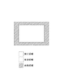
次に、電子像振れ補正の処理について説明する。図7は、電子像振れ補正量演算の処理を説明するための処理フローである。また、図8は、撮像面上の実行領域、有効領域及び余剰領域を示す図である。
<Electronic image blur correction processing>
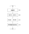
Next, electronic image shake correction processing will be described. FIG. 7 is a processing flow for explaining processing of electronic image shake correction amount calculation. FIG. 8 is a diagram illustrating an execution area, an effective area, and a surplus area on the imaging surface.
本実施の形態に係る撮像装置10は、上述したように、像振れ検出部400において検出された像振れ信号を演算部500に出力し、その像振れ信号から、HPF501に通過させて抽出された高周波成分の像振れ信号を減算部502を介して減算することによって低周波成分からなる像振れ信号を抽出する。そして、抽出した高周波成分の像振れ信号は電子像振れ補正演算部504に出力され、この電子像振れ補正演算部504は、まずステップS301において、抽出した低周波成分からなる像振れ信号から角速度を取得する。
As described above, the
具体的には、上述した光学像振れ補正処理におけるジャイロセンサ等の角速度センサと同様に、x方向及びy方向の位置移動量が検出され、電子像振れ補正演算部504は、この位置移動量から角速度を取得する。
Specifically, similarly to the angular velocity sensor such as the gyro sensor in the above-described optical image shake correction process, the position movement amount in the x direction and the y direction is detected, and the electronic image shake
このようにして、ステップS301にて抽出した低周波成分からなる像振れ信号の角速度を取得すると、電子像振れ補正演算部504は、次にステップS302において、下記に示す式のように、その取得した角速度を時間積分することによって補正角度を算出する。
補正角度=∫角速度dt
In this way, when the angular velocity of the image blur signal composed of the low frequency component extracted in step S301 is acquired, the electronic image blur
Correction angle = Depression speed dt
そして、ステップS302にて補正角を算出すると、電子像振れ補正演算部504は、次にステップS303において、下記に示す式に基づき、算出した補正角度を補正画素に変換する。電子像振れ補正処理の場合は、補正単位が補正角度ではなく補正画素であるので、算出した補正角度から補正が画素に変換することが必要となる。
補正画素=f(補正角度)
When the correction angle is calculated in step S302, the electronic image shake
Correction pixel = f (correction angle)
この補正画素を算出する関係式の一例としては、例えば、像振れ信号の角速度から算出した補正角度が微小である場合には、下記に示す数式等により算出することができるが、当然これに限られるものではない。
補正画素=補正角度×光学倍率
As an example of the relational expression for calculating the correction pixel, for example, when the correction angle calculated from the angular velocity of the image blur signal is very small, the correction pixel can be calculated by the following mathematical formula, but of course, it is not limited to this. It is not something that can be done.
Correction pixel = Correction angle x Optical magnification
このようにして、電子像振れ補正演算部504は、ステップS303にて補正角度から補正画素を算出すると、ステップS304において、算出した補正画素を、画像処理ユニット200における像振れ補正部202に対して指示する。
In this way, when the electronic image blur
このような電子像振れ補正処理のフローにより、減算部502より出力された像振れの低周波成分は、電子像振れ補正演算部504により補正画素が決定され、電子像振れ補正演算部504はその補正画素を像振れ補正部202に対して指示する。そして、像振れ補正部202において、その供給された補正画素に基づいて算出した補正ベクトルにより、記録部300に像振れの低周波成分が打ち消された状態で画像が記録される。
According to the flow of the electronic image blur correction process, a correction pixel is determined by the electronic image blur
より具体的に説明すると、検出した低周波成分の像振れ信号から算出された補正画素に基づいて補正ベクトルが生成されると、図8に示す余剰領域を用いて、有効領域の範囲内で像振れによって移動した実行領域を、その補正ベクトルに従って移動させる。これにより、記録部300に像振れの低周波成分が打ち消された状態で画像が記録される。なお、本明細書においては、図8で示す有効領域とは、撮像面上の全領域を意味し、実行領域とは、像振れ補正で抽出する有効領域の一部分を意味し、また余剰領域とは、像振れ補正に使用するための領域を意味するものとする。
More specifically, when a correction vector is generated based on a correction pixel calculated from an image shake signal of a detected low frequency component, an image is generated within the effective area using the surplus area shown in FIG. The execution area moved by the shake is moved according to the correction vector. As a result, an image is recorded in the
本実施の形態に係る撮像装置10は、この電子像振れ補正と、上で説明した光学像振れ補正と組み合わせることで、高周波成分からなる像振れと低周波成分からなる像振れの両方を打ち消した状態で記録することができる。例えば、車等の移動体から撮像したときに生じる大振幅からなる低周波成分からなる像振れに、ユーザの手振れ等による小振幅からなる像振れが混合したような場合では、それぞれの周波数帯域からなる像振れを精度高く補正処理することが可能となる。
The
このように、光学像振れ補正と電子像振れ補正とを組み合わせることによって、振幅の大きな像振れに対しても、補正余裕を十分に確保することができ、効果的な像振れ補正を実現することができる。 In this way, by combining optical image blur correction and electronic image blur correction, a sufficient correction margin can be secured even for image blur with a large amplitude, and effective image blur correction can be realized. Can do.
また、電子像振れ補正処理では補正することができない露光中の像振れに対しても、光学像振れ補正処理を併用することで補正することが可能となる。 Also, image blur during exposure that cannot be corrected by the electronic image blur correction process can be corrected by using the optical image blur correction process together.
ところで、上述したように、本実施の形態に係る撮像装置10では、高周波成分からなる像振れ信号に対しては光学像振れ補正処理を施し、低周波成分に対しては電子像振れ補正処理を施すようにしているが、像振れ信号の低周波成分を電子像振れ補正にて処理する場合には、その用いる撮像素子の読み出し方式の違いにより、補正処理にも違いが生じる。
By the way, as described above, in the
以下では、本実施の形態に係る撮像装置10の、撮像素子別による電子像振れ補正処理について説明していく。
Hereinafter, the electronic image shake correction process for each imaging element of the
<撮像素子別の補正処理>
本実施の形態に係る撮像装置10では、その撮像素子103として、CCDセンサやCMOSセンサのどちらを用いるようにしてもよいが、CCDセンサとCMOSセンサでは読み出し方式が異なるため、露光タイミングがそれぞれ異なり、各撮像素子に適合した制御を行う必要がある。
<Correction process for each image sensor>
In the
具体的には、CCDセンサは、読み出し方式が電荷転送型の固体撮像素子であり、このCCDセンサの場合には、全画素を同時期に露光して、画素データを読み出すことが可能となっている。そして、このCCDセンサを用いた像振れ補正処理においては、全ての画素の露光期間が等しく、画像の歪みが生じないために、像振れによる影響を低減させるための処理を実行する上で必要とされる像振れ補正量は、1フィールドまたは1フレーム内で得られた像振れ情報に基づいて算出された単一の値を用いて処理することができる。 Specifically, the CCD sensor is a solid-state imaging device whose charge is read out, and in the case of this CCD sensor, it is possible to read out pixel data by exposing all pixels at the same time. Yes. In the image blur correction process using the CCD sensor, since the exposure periods of all the pixels are equal and the image is not distorted, it is necessary to execute the process for reducing the influence of the image blur. The image blur correction amount to be processed can be processed using a single value calculated based on the image blur information obtained in one field or one frame.
図9は、CCDセンサの像振れ補正処理タイミングを示すものである。上述したように、撮像素子としてCCDセンサを用いた場合の電子像振れ補正処理は、全画素の像振れ補正量が同じであるため、画像更新周期に1回のみ補正処理が動作する。 FIG. 9 shows image blur correction processing timing of the CCD sensor. As described above, in the electronic image blur correction process when the CCD sensor is used as the image sensor, the image blur correction amount of all the pixels is the same, and thus the correction process operates only once in the image update period.
これに対して、CMOSセンサは、読み出し方式が2次元アドレス型の固体撮像素子であり、1画素単位あるいは1ライン単位で順番に読み出されるようになっている。 On the other hand, the CMOS sensor is a solid-state imaging device having a two-dimensional address reading method, and is read in order in units of one pixel or one line.
さらに詳細にライン単位で読み出しを行う撮像素子であるCMOSセンサについて図10を参照にして説明する。図10は、CMOSセンサのライン毎の読み出しのずれについて説明するための図である。ここでは、全画素の読出し周期が1/T秒で、1画素がラインy0乃至ラインy2で構成されるCMOSセンサの場合を例に挙げて説明する。なお、説明の便宜上、図10(B)では1画面中におけるラインy0、ラインy1、ラインy2の3つのラインを抽出し、各ライン毎の電荷蓄積の様子と読み出しタイミングのずれについて示す。 A CMOS sensor, which is an image sensor that performs readout in line units, will be described in detail with reference to FIG. FIG. 10 is a diagram for explaining a reading shift for each line of the CMOS sensor. Here, a description will be given by taking as an example a CMOS sensor in which the readout cycle of all pixels is 1 / T second and one pixel is composed of lines y0 to y2. For convenience of explanation, FIG. 10B shows three lines of line y0, line y1, and line y2 in one screen, and shows the state of charge accumulation for each line and the deviation of the read timing.
この図10(B)を参照すると、ラインy0の露光期間は、開始時刻が時刻t1であり、終了時刻が時刻t2である。ラインy1の露光期間の終了時間は、時刻t3であり、ラインy2の露光期間の終了時間は、時刻t4である。 Referring to FIG. 10B, in the exposure period of line y0, the start time is time t1, and the end time is time t2. The end time of the exposure period for line y1 is time t3, and the end time of the exposure period for line y2 is time t4.
時刻t2と時刻t3との時間差は時間差Δtであり、時刻t3と時刻t4の時間差は時間差Δtである。すなわち、露光期間は、1ライン毎に時間差が時間差Δtだけ生じることになる。したがって、画面の一番上のラインy0と一番下のラインy2とでは、この場合、露光期間に1/T秒に近い時間差が発生することになる。このように、1画像を読み出す際、一番上のラインy0と一番下のラインy2とでは露光期間に1/T秒に近い時間差(露光期間のずれ)が生じるため、このずれが生じる状況下で像振れが生じた場合、このライン毎による露光期間の時間差により、被写体である物体の画像が変形してしまうこととなる。 The time difference between time t2 and time t3 is a time difference Δt, and the time difference between time t3 and time t4 is a time difference Δt. That is, in the exposure period, a time difference is generated for each line by the time difference Δt. Therefore, in this case, a time difference close to 1 / T second occurs in the exposure period between the uppermost line y0 and the lowermost line y2. Thus, when one image is read out, a time difference (exposure period deviation) close to 1 / T second occurs in the exposure period between the uppermost line y0 and the lowermost line y2, and this deviation occurs. When image blur occurs below, the image of the object that is the subject is deformed due to the time difference of the exposure period for each line.
図11は、CMOSセンサの像振れ補正処理タイミングを示すものである。上述したように、撮像素子としてCMOSセンサを用いた場合の電子像振れ補正処理において、1フィールドまたは1フレーム内で得られた像振れ信号情報に基づいて算出された単一の補正量で像振れ補正処理を行った場合、各ライン毎に露光期間のずれ(撮像のタイミングのずれ)が生じるため、像振れの影響を完全に取ることができない。そして、結果として、ユーザに提供される画像が歪んだ画像となってしまうことが考えられる。したがって、CMOSセンサを用いて電子像振れ補正処理を施す場合には、CCDセンサのように全画素同一補正量ではなく、1画面中の各ライン毎に補正量を算出して補正処理を行うことが必要となる。 FIG. 11 shows image blur correction processing timing of the CMOS sensor. As described above, in an electronic image blur correction process when a CMOS sensor is used as an image sensor, image blur is performed with a single correction amount calculated based on image blur signal information obtained in one field or one frame. When the correction process is performed, a shift in exposure period (shift in imaging timing) occurs for each line, so that the influence of image blur cannot be completely taken. As a result, the image provided to the user may be distorted. Therefore, when electronic image blur correction processing is performed using a CMOS sensor, correction processing is performed by calculating a correction amount for each line in one screen, not the same correction amount for all pixels as in the CCD sensor. Is required.
このように、画像更新周期と独立して処理することができる光学像振れ補正演算は、画像更新周期とは別の同期で処理できるのに対し、画像更新の同期で処理する電子像振れ補正演算は、撮像素子の読み出し方式に依存し、画像更新周期に同期して処理する必要がある。そして、一般的にCCDセンサでは、全ての画素は露光の開始と終了のタイミングが同じであるため各画素の同時性があるのに対して、CMOSセンサでは画素毎の同時性がなく、それぞれ露光タイミングが異なる。 In this way, the optical image shake correction calculation that can be processed independently of the image update period can be processed in synchronization with the image update period, whereas the electronic image shake correction calculation that is processed in synchronization with the image update period. Depends on the readout method of the image sensor and needs to be processed in synchronization with the image update cycle. In general, in the CCD sensor, all pixels have the same timing for the start and end of exposure, whereas in the CMOS sensor, there is no synchronism for each pixel. Timing is different.
近年、高精細装置の普及による撮像素子の多画素化が一般化しており、多画素の撮像素子を高速に読み出すには、XYアドレス走査型の読み出し行うことが必要とされている。また、このXYアドレス走査型の撮像素子では、各画素の信号を選択方式で取り出すため、取り出す順番を容易に変えることができ、走査の自由度が高く、この点においても高精細な装置への適用が望ましい。したがって、これらの観点から近年では、撮像素子としてCMOSセンサを適用させることへの要望が強くなっている。 In recent years, an increase in the number of pixels of an image sensor due to the spread of high-definition devices has become common, and in order to read out a multi-pixel image sensor at high speed, it is necessary to perform XY address scanning type readout. Further, in this XY address scanning type image pickup device, since the signal of each pixel is extracted by a selection method, the extraction order can be easily changed, and the degree of freedom in scanning is high. Application is desirable. Therefore, from these viewpoints, in recent years, there has been a strong demand for applying a CMOS sensor as an image sensor.
さらに、CMOSセンサでは、以下のような利点を有している、すなわち、2次元アドレス走査型のCMOSセンサでは、電荷転送型のCCDセンサと比べて、その動作方式の違いからノイズひとつであるスミアの発生をなくすことができるとともに、CMOSセンサの場合には、より小さい消費電力で駆動させることが可能となっている。 Further, the CMOS sensor has the following advantages, that is, the two-dimensional address scanning type CMOS sensor has a smear that is one noise due to the difference in operation method compared to the charge transfer type CCD sensor. In the case of a CMOS sensor, it is possible to drive with less power consumption.
そこで、以下では、撮像素子103としてCMOSセンサを用いた場合の、本実施の形態に係る撮像装置10の電子像振れ補正処理について詳細に説明していく。
Therefore, in the following, the electronic image shake correction processing of the
上述したように、電子像振れ補正処理においては、撮像素子103としてCMOSセンサを用いた場合、読み出し方式により各ライン毎の露光タイミングが異なることから、その複数分割された領域(ライン)毎に像振れに対する補正量を算出することが必要となってくる。
As described above, in the electronic image blur correction process, when a CMOS sensor is used as the
図12は、各ライン毎に異なった補正ベクトルを適応させることを説明するための模式図である。図12(A)は、1画像中のライン0、ラインn、ラインNにおける時間tに対する像振れ検出ベクトルvを示す。すなわち、関数f(t)によって時間tにおける像振れベクトルを算出する。また、図12(B)は、各ラインにおける補正ベクトルを示している。
FIG. 12 is a schematic diagram for explaining that different correction vectors are applied to each line. FIG. 12A shows an image blur detection vector v with respect to time t at
上述したように、撮像素子103としてCMOSセンサを用いた場合には、1画像中における各ライン毎に露光タイミングが異なる。したがって、図12に示すように、各ライン毎に像振れベクトルも相違し、その像振れベクトルを打ち消すように各ライン毎に補正ベクトル量を算出することが必要となり、電子像振れ補正演算部504にて各ライン毎に像振れ量と補正量を算出することにより、像振れをキャンセルする。
As described above, when a CMOS sensor is used as the
図13は、画像の更新周期と各ラインにおける電荷蓄積タイミングを示す図である。なお、この図11中において、TBは画像更新周期、TCは電荷蓄積期間、TSは電子シャッター時の掃き捨て蓄積期間、Nはライン数、TOは光学像振れ補正演算部の検出と補正の周期、TEは電子像振れ補正演算部の周期を示している。 FIG. 13 is a diagram illustrating an image update cycle and charge accumulation timing in each line. Note that in FIG. 11, T B is the image update period, T C is the charge accumulation period, T S is sweeping accumulation period of time of the electronic shutter, N is the number of lines, T O is the optical image blur correction arithmetic section of the detection a period of correction, T E denotes the period of the electronic image blur correction arithmetic section.
この図13から判るように、本実施の形態の係る撮像装置10においては、電子シャッター機能が備えられている。電子シャッターは、1回の水平走査期間につき1回の電荷掃き捨てパルスを印加することで、それまでにCMOSセンサの受光部に蓄積された不要電荷を掃き捨てる機能であり、これにより適切な電荷蓄積が行われる。そして、電子シャッターをOFFにし、すぐに露光を開始することで、再び電荷の蓄積させることができる。これにより不要な電荷を蓄積させずに、必要な電荷だけがCMOSセンサの受光部に蓄積した状態を保持できる。また、このように電子シャッター機能を備えることにより、過度の電荷蓄積時間、すなわち過度の露光時間による像振れの発生を防止することが可能となる。
As can be seen from FIG. 13, the
本実施の形態に係る撮像装置10においては、このように、電子シャッター機能を備えているので適切な電荷蓄積を行うことが可能となるが、装置に発生した像振れを検出し、その検出した像振れ信号に基づいて電子像振れ補正量を算出するに際しては、画像更新周期TB中における電子シャッターよる電荷掃き捨て期間を考慮して、電荷蓄積期間TCの中心、換言すると有効露光期間の中心(露光中心)における像振れ信号を検出し、その検出した像振れ信号から補正量を算出することが必要となる。
In the
この図13を参照して、例えば、60Hzの画像更新周期TBあたりに、電子像振れ補正のサンプリング周波数480Hzでサンプリングポイントを設定するような場合、電子シャッターによる電荷掃き捨て期間TSを考慮して電荷蓄積期間TCの露光中心にサンプリングタイミングが合致するように設定することが望ましいが、電子シャッターによる電荷掃き捨て期間TSを任意に設定した場合には、必ずしも露光中心がサンプリングタイミングに合致させることができるとは限らない。 The 13 See, for example, the image update period T per B of 60 Hz, if the sampling frequency 480Hz of the electronic image blur correction to set the sampling point, taking into account the time period T S charge sweep by the electronic shutter it is desirable to set such sampling timing matches the exposure center of the charge accumulation period T C Te, when arbitrarily set time period T S charge sweep by the electronic shutter is always exposed center matches the sampling timing It may not always be possible.
そこで、本実施の形態に係る撮像装置10では、適切な像振れ信号を検出し、その像振れ信号に対して適切な補正量を算出するために、1画像中の各ライン毎の露光中心における像振れ信号を算出し、一定周期の各サンプリングポイントにおける像振れ信号の検出結果を補間するようにしている。具体的には、下記の数式1から、各ラインの露光中心に相当する時間tを算出し、その算出結果から、図12に示したように、各ライン毎に補正ベクトルvを算出することができるようになっている。
Therefore, in the

このように、本実施の形態に係る撮像装置10では、画像更新周期TBにおけるサンプリングポイントにおいて検出する像振れ信号を補間し、補間した検出結果に基づいて補正量を算出するようにしているので、精度の高い像振れ信号検出と、その像振れに対する補正量の算出が可能となっている。また、任意に電子シャッター機能を実行させた場合でも、上記数式1より電荷蓄積期間TCにおける露光中心tを算出することで、適切な像振れ補正量を算出することができる。
Thus, the
従来の撮像装置における電子像振れ補正処理においては、撮像素子としてCMOSセンサを用いた場合、画面上部と下部では露光タイミングにずれが生じてしまうため、画像による像振れの検出は、結像面の被写体の時間的なずれが問題となっていた。このことから、領域毎に時間的に異なるものを比較することは難しく、検出誤差につながりやすくなるという問題があった。また、画像検出は被写体の影響を受けやすいので、ローコントラスト、高周波画像、S/Nが悪い画像等では、像振れ信号を誤検出するという問題があった。 In the electronic image shake correction processing in the conventional image pickup apparatus, when a CMOS sensor is used as the image pickup device, the exposure timing is shifted between the upper and lower portions of the screen. The time lag of the subject was a problem. For this reason, it is difficult to compare different areas for each region, and there is a problem in that it tends to lead to detection errors. Further, since image detection is easily influenced by the subject, there is a problem that an image blur signal is erroneously detected in a low contrast, a high frequency image, an image with a poor S / N, or the like.
しかしながら、本実施の形態に係る撮像装置10によれば、サンプリングタイミングにおける像振れ信号検出に補間するようにして、電荷蓄積期間TCの露光中心tにおける像振れ信号を検出し、その時点における補正ベクトルvを算出するようにし、算出した補正ベクトルvを、画像処理ユニット200における像振れ補正部202に供給するようにしている。これにより、上記の問題を解決するとともに、精度の高い、電子像振れ補正処理をすることができる。
However, according to the
そして、このように、精度の高い電子像振れ補正処理を実現させることで、振幅が大きい像振れ信号が多い低周波数帯域の像振れに対して、的確に補正処理を施すことができる。 As described above, by realizing highly accurate electronic image blur correction processing, it is possible to accurately perform correction processing on image blur in a low frequency band with a large amplitude image blur signal.
以上、本実施の形態に係る撮像装置10における、光学像振れ補正処理と電子像振れ補正処理について説明した。本実施の形態に係る撮像装置10は、このように、光学像振れ補正と電子像振れ補正とを組み合わせて像振れ補正処理を施すようにしているので、容易に十分な補正余裕を確保することが可能となり、振幅の大きな像振れに対しても、精度高く補正処理を施すことができる。
The optical image shake correction process and the electronic image shake correction process in the
また、これにより、従来の撮像装置に比して、レンズユニットのおけるレンズやアクチュエーターの大型化を防止することができ、それに伴う装置の重量化を防止することができる。さらに、レンズをシフト駆動するための消費電力の増大、またさらにレンズを大きくシフトさせることによる光学性能劣化等を防止することもできる。 In addition, this makes it possible to prevent the lenses and actuators in the lens unit from becoming larger than the conventional imaging device, and to prevent the weight of the device from being increased accordingly. Further, it is possible to prevent an increase in power consumption for driving the lens to be shifted and a deterioration in optical performance due to a large shift of the lens.
また、電子像振れ補正処理を採用していた従来の撮像装置に比して、補正角を十分に確保することに伴う実効領域の縮小による画像劣化等を防止することが可能となる。 In addition, as compared with a conventional imaging apparatus that employs electronic image shake correction processing, it is possible to prevent image deterioration due to reduction of the effective area associated with ensuring a sufficient correction angle.
<補正量の分配制御フロー>
上述したように、本実施の形態に係る撮像装置10によれば、光学像振れ補正処理と電子像振れ補正処理とを組み合わせることによって、大きい補正角を確保することができ、振幅の大きな像振れに対しても、効率的に像振れ補正処理を施すことができる。
<Correction amount distribution control flow>
As described above, according to the
一方でまた、この本実施の形態に係る撮像装置10では、装置に生じた像振れを補正するための補正角が比較的小さい場合、すなわち補正量が小さい場合には、光学像振れ補正を優先的に補正手段として用いることも可能となっている。このように、補正角が小さい場合には光学像振れ補正を優先的に処理することによって、電子像振れ補正処理に伴う画像劣化等の問題発生を防止することができる。また、撮像装置10の演算量を抑えることも可能となり、必要最小限の電力で、高速に補正処理を施すことができる。
On the other hand, in the
また、このように光学像振れ補正処理を優先的に行うことにより、露光中の像振れ補正処理を可能にすることができる。光学像振れ補正と電子像振れ補正の相違として、撮像素子の露光振れに対する補正の対応の有無があり、光学像振れ補正の場合には露光中も補正が可能であるのに対して、電子像振れ補正の場合には露光中に像振れを補正することはできない。上述したように、電子像振れ補正の場合、例えば撮像素子としてCMOSセンサを用いた場合では、その露光タイミングにずれが生じてしまうため、1画像中の各ライン毎に補正量が異なり、露光中に補正ができないことによる影響をさらに大きくしてしまう。 In addition, by preferentially performing the optical image blur correction process in this way, it is possible to perform the image blur correction process during exposure. As a difference between optical image shake correction and electronic image shake correction, there is the presence or absence of correction for exposure shake of the image sensor. In the case of optical image shake correction, correction is possible during exposure, while electronic image shake correction is possible. In the case of shake correction, image shake cannot be corrected during exposure. As described above, in the case of electronic image shake correction, for example, when a CMOS sensor is used as an imaging device, the exposure timing is shifted, so the correction amount differs for each line in one image, and exposure is in progress. The effect of not being able to correct is further increased.
そこで、本実施の形態に係る撮像装置10においては、補正量限界に基づいて制御することにより、光学像振れ補正処理を優先させる処理を行うようにしており、これにより、露光中の像振れ補正を可能な限り可能にし、露光中に生じる被写体振れ等を最小限に抑えることができる。以下に、光学像振れ補正処理優先制御機構について、再び図6のブロック図と、さらに図14のフローチャートを参照にして詳細に説明する。
Therefore, in the
上述したように、図6は、本実施の形態に係る撮像装置10の他の構成例の一例を表すブロック図であり、各補正演算部503,504における補正限界に基づいた制御を行うものである。
As described above, FIG. 6 is a block diagram illustrating an example of another configuration example of the
この図6に示すように、撮像装置10の演算部500には、図1を参照にして上で説明した構成の他に、さらにリミット制御部506と、レンズシフトドライバ指示部507と、電子補正指示部508とを備えている。
As shown in FIG. 6, in addition to the configuration described above with reference to FIG. 1, the
像振れ検出部400にて検出した像振れ信号のうち、高周波成分の像振れ信号は光学像振れ補正演算部503に、低周波成分の像振れ信号は電子像振れ補正演算部504に入力され、各補正演算部503,504にて補正量が算出されると、その補正量はリミット制御部506に出力される。このリミット制御部506では、各補正演算部503,504にて算出された補正量を統合するとともに、各補正演算部503,504にて算出された像振れに対する全補正量が、光学補正及び電子補正の補正限界(補正量max)にあるか否かを判断する。そして、このリミット制御部506からの補正量情報は、光学像振れ補正処理を施すためにレンズシフトドライバ104に指示するためのレンズシフトドライバ指示部507と、電子像振れ補正処理を施すために像振れ補正部202に指示するための電子補正指示部508に、それぞれ出力される。そして、これらの指示部からの指示に基づき、補正処理が施される。このように構成された本実施の形態に係る撮像装置10は、このリミット制御部506における制御に基づいて、光学像振れ補正処理を優先させる処理を行うことができるようになっている。
Among the image blur signals detected by the image
ここで、より具体的に、図14のフローを参照して、光学像振れ補正処理優先制御機構について詳細に説明する。図14は、本実施の形態に係る撮像装置10の、光学像振れ補正処理を優先的に用いる動作制御を説明するための制御フローである。
Here, more specifically, the optical image shake correction processing priority control mechanism will be described in detail with reference to the flow of FIG. FIG. 14 is a control flow for explaining the operation control that preferentially uses the optical image shake correction process of the
本実施の形態に係る撮像装置10は、上述したように、像振れ検出部400において、撮像装置10の移動に伴う像振れを検出すると、その像振れ信号を演算部500に出力し、HPF501を通過させて像振れ信号を高周波成分と低周波成分に分離する。そして、まずステップS401において、分離した各像振れ信号のうち、高周波成分の像振れ信号に対しては光学像振れ補正演算処理を施し、低周波成分の像振れ信号に対しては電子像振れ補正演算処理を施す。
As described above, when the image
具体的には、上述したように、像振れ検出部400において検出された像振れ信号が演算部500に入力され、HPF501において検出された像振れ信号のうちの高周波成分が抽出されると、その高周波帯域の像振れ信号は光学像振れ補正演算部503にて補正量が算出される。一方、像振れ検出部400にて検出された全像振れ信号からHPF501にて抽出された高周波帯域の像振れ信号が減算部502において差し引かれることによって抽出された低周波帯域の像振れ信号は、電子像振れ補正演算部504にて補正量が算出される。
Specifically, as described above, when the image blur signal detected by the image
このようにして、まずステップS401にて、検出された像振れ信号のうち高周波成分が光学像振れ補正演算部503で、低周波成分が電子像振れ補正演算部504で、それぞれ補正量が算出されると、次にステップS402において、総合像振れ補正量と光学像振れ補正量の比較を行う。すなわち、ステップS401において、光学像振れ補正演算部503にて算出された補正量と電子像振れ補正演算部504にて算出された補正量とを合算した像振れに対する全補正量(総合補正量)と、光学像振れ補正限界量とを比較する。そして、この比較の結果、「総合像振れ補正量(Vt)>光学像振れ補正限界(Vo_max)」である場合(ステップS402にてYES:Yの場合)にはステップS403に進む。一方、比較の結果、「総合像振れ補正量(Vt)>光学像振れ補正限界(Vo_max)」ではない場合(ステップS402にてNO:Nの場合)にはステップS404に進む。
In this way, first, in step S401, the correction amount is calculated by the optical image shake
ステップS402にて「総合像振れ補正量(Vt)>光学像振れ補正限界(Vo_max)」であると判断されると、ステップS403において、
光学像振れ補正量(Vo)=光学像振れ補正量限界(Vo_max)
電子像振れ補正量(Ve)=総合像振れ補正量(Vt)−光学像振れ補正量限界(Vo_max)
を設定し、次にステップS405に進む。
If it is determined in step S402 that “total image shake correction amount (Vt)> optical image shake correction limit (Vo_max)”, in step S403,
Optical image shake correction amount (Vo) = Optical image shake correction amount limit (Vo_max)
Electronic image shake correction amount (Ve) = Total image shake correction amount (Vt) −Optical image shake correction amount limit (Vo_max)
Then, the process proceeds to step S405.
一方で、ステップS402にて、「総合像振れ補正量(Vt)>光学像振れ補正限界(Vo_max)」ではないと判断されると、ステップS404において、
光学像振れ補正量(Vo)=総合像振れ補正量(Vt)
電子像振れ補正量=0
を設定する。このステップS404において、このようにして光学像振れ補正量(Vo)=総合像振れ補正量(Vt)が設定されて、検出した像振れ信号のすべてが光学像振れ補正によって処理されるように設定されると、この制御フローの処理は終了となり、光学像振れ補正演算部503にて算出された補正量は、撮像装置10のレンズユニット100におけるレンズシフトドライバ104に出力され、その補正量に基づきシフト防振レンズ102を制御して光学像振れ補正処理を実行する。
On the other hand, if it is determined in step S402 that “total image shake correction amount (Vt)> optical image shake correction limit (Vo_max)” is not satisfied, in step S404,
Optical image blur correction amount (Vo) = Total image blur correction amount (Vt)
Electronic image shake correction amount = 0
Set. In this step S404, the optical image blur correction amount (Vo) = the total image blur correction amount (Vt) is set in this way, and all the detected image blur signals are processed by the optical image blur correction. Then, the processing of this control flow ends, and the correction amount calculated by the optical image shake
ステップS403にて光学像振れ補正量(Vo)と電子像振れ補正量(Ve)が設定されると、次にステップS405において、電子像振れ補正量(Ve)と電子像振れ補正限界(Ve_max)の比較を行う。すなわち、ステップS403にて総合像振れ補正量(Vt)から光学像振れ補正限界(Vo_max)に設定された光学像振れ補正量(Vo)を差し引くことによって決定された電子像振れ補正量(Ve)が、電子像振れ補正限界(Ve_max)よりも大きいか否かの判断が行われる。そして、この比較の結果、「電子像振れ補正量(Ve)>電子像振れ補正限界(Ve_max)」である場合(ステップS405にてYES:Yの場合)には、ステップS406に進む。一方、比較の結果、「電子像振れ補正量(Ve)>電子像振れ補正限界(Ve_max)」ではない場合(ステップS402にてNO:Nの場合)には、ステップS407に進む。 When the optical image shake correction amount (Vo) and the electronic image shake correction amount (Ve) are set in step S403, next, in step S405, the electronic image shake correction amount (Ve) and the electronic image shake correction limit (Ve_max). Make a comparison. That is, the electronic image blur correction amount (Ve) determined by subtracting the optical image blur correction amount (Vo) set to the optical image blur correction limit (Vo_max) from the total image blur correction amount (Vt) in step S403. Is determined to be greater than the electronic image blur correction limit (Ve_max). As a result of the comparison, if “electronic image shake correction amount (Ve)> electronic image shake correction limit (Ve_max)” (YES in step S405: Y), the process proceeds to step S406. On the other hand, as a result of comparison, if “electronic image shake correction amount (Ve)> electronic image shake correction limit (Ve_max)” is not satisfied (NO in step S402: NO), the process proceeds to step S407.
ステップS405にて「電子像振れ補正量(Ve)>電子像振れ補正限界(Ve_max)」であると判断されると、ステップS406において、
光学像振れ補正量(Vo)=光学像振れ補正量限界(Vo_max)
電子像振れ補正量(Ve)=電子像振れ補正量限界(Ve_max)
を設定し、この制御フローの処理は終了となる。そして、光学像振れ補正限界に設定された光学像振れ補正量は、光学像振れ補正演算部503からレンズユニット100におけるレンズシフトドライバ104に出力されて、その補正量に基づいてシフト防振レンズ102を制御して光学像振れ補正処理を実行する。また、電子像振れ補正限界に設定された電子像振れ補正量は、電子像振れ補正演算部504から、撮像装置10における画像処理ユニット200の像振れ補正部202に出力されて、その補正量に基づいて電子像振れ補正処理を実行する。
If it is determined in step S405 that “electronic image shake correction amount (Ve)> electronic image shake correction limit (Ve_max)”, in step S406,
Optical image shake correction amount (Vo) = Optical image shake correction amount limit (Vo_max)
Electronic image blur correction amount (Ve) = Electronic image blur correction amount limit (Ve_max)
Is set, and the processing of this control flow ends. The optical image shake correction amount set at the optical image shake correction limit is output from the optical image shake
一方で、ステップS405にて「電子像振れ補正量(Ve)>電子像振れ補正限界(Ve_max)」ではないと判断されると、ステップS407において、
光学像振れ補正量(Vo)=光学像振れ補正量限界(Vo_max)
電子像振れ補正量(Ve)=総合像振れ補正量(Vt)−光学像振れ補正量限界(Vo_max)
を設定し、この制御フローの処理は終了となり、ステップS403において設定された補正量まま、補正処理を実行することとなる。すなわち、光学像振れ補正限界に設定された光学像振れ補正量は、光学像振れ補正演算部503からレンズユニット100におけるレンズシフトドライバ104に出力されて、その補正量に基づいてシフト防振レンズ102を制御して光学像振れ補正処理を実行する。また、総合像振れ補正量(Vt)から光学像振れ補正限界(Vo_max)に設定された光学像振れ補正量(Vo)を差し引くことによって決定された電子像振れ補正量(Ve)は、電子像振れ補正演算部504から、撮像装置10における画像処理ユニット200の像振れ補正部202に出力され、その補正量に基づいて電子像振れ補正処理を実行する。
On the other hand, if it is determined in step S405 that “electronic image shake correction amount (Ve)> electronic image shake correction limit (Ve_max)” is not satisfied, in step S407,
Optical image shake correction amount (Vo) = Optical image shake correction amount limit (Vo_max)
Electronic image shake correction amount (Ve) = Total image shake correction amount (Vt) −Optical image shake correction amount limit (Vo_max)
This control flow process ends, and the correction process is executed with the correction amount set in step S403. That is, the optical image shake correction amount set at the optical image shake correction limit is output from the optical image shake
以上、図6及び図14を用いて説明したように、本実施の形態に係る撮像装置10は、像振れ信号に対する補正量を算出する演算部500において、リミット制御部506を備えており、補正量演算結果に基づいて、補正量を制御することができるようになっている。具体的に、このリミット制御部506は、光学像振れ補正演算部503と電子像振れ補正演算部504とで算出された補正量から全補正量を算出する。また、このリミット制御部506は、光学像振れ補正及び電子像振れ補正の補正限界量に関する情報を保持しており、全補正量と光学像振れ補正限界量とを比較する。さらに、各補正演算部503,504にて算出された各補正量と各像振れ補正限界量とを比較する。
As described above with reference to FIGS. 6 and 14, the
そして、例えば、検出された像振れ信号に基づいて光学像振れ補正演算部及び電子像振れ補正演算部にて算出された全補正量と光学像振れ補正限界量とを比較し、算出された全補正量が光学像振れ補正限界量以下の場合には、検出された像振れ信号に対して光学像振れ補正を優先的に実行させる。このように、リミット制御部506の制御に基づき光学像振れ補正を優先させることにより、撮像装置における演算負荷を軽減することができるとともに、電力消費を抑え、また高速な補正処理を実行することができる。また、露光中の像振れ補正を可能にし、精度の高い像振れ処理を実行することができるようにしている。
Then, for example, by comparing the total correction amount calculated by the optical image blur correction calculation unit and the electronic image blur correction calculation unit with the optical image blur correction limit amount based on the detected image blur signal, When the correction amount is equal to or less than the optical image blur correction limit amount, the optical image blur correction is preferentially executed on the detected image blur signal. Thus, by giving priority to optical image shake correction based on the control of the
また、光学像振れ補正処理を優先して行わせることにより、撮像素子から読み出された後に擬似的に像振れを補正する電子像振れ補正処理に比べて、像振れによる画像劣化をより低減することができる。 Also, by giving priority to the optical image blur correction process, image degradation due to image blur is further reduced as compared with an electronic image blur correction process in which image blur is corrected in a pseudo manner after being read from the image sensor. be able to.
なお、上述した光学像振れ補正を優先して行わせる制御に際して、演算部500に備えられている信号解析部505による振幅の大きさに関する信号解析結果を反映させて制御するようにしてもよい。すなわち、信号解析部505が、検出した像振れ信号が小振幅信号であると解析すると、その解析結果に関する情報を、例えば、リミット制御部506に供給する。そして、リミット制御部506は、その供給された情報を利用して、光学像振れ補正を優先して行わせるようにしてもよい。また、信号解析部505が小振幅信号であるとの信号解析を行うと、その解析結果に関する情報を、例えば、HPF501に供給する。そして、HPF501は、その供給された情報を利用して、周波数帯域別に分離するカットオフ機能を停止し、全ての像振れ信号を光学像振れ補正演算部503に出力するようにし、全像振れ信号に対する光学像振れ補正量に基づいて光学像振れ補正を行わせるようにしてもよい。
In the control for giving priority to the above-described optical image shake correction, the control may be performed by reflecting the signal analysis result related to the magnitude of the amplitude by the
上述したように、本実施の形態に係る撮像装置10は、光学像振れ補正処理と電子像振れ補正処理とを周波数帯域別に実行することが可能となっている。そしてまた、本実施の形態に係る撮像装置10においては、その光学像振れ補正処理と電子像振れ補正処理とを実行するに際し、統一した検出部である像振れ検出部400によって検出した像振れ信号を、像振れ検出部と像振れ演算部とが一元管理可能なように構成された演算部500に出力して、各補正処理量を算出するようにしている。これにより、光学像振れ補正部と電子像振れ補正部の双方の整合性をとることが容易になり、所望の像振れ補正結果を得易くすることができる。
As described above, the
さらに、このように各補正処理を一元管理することによって、上述したような信号解析部505による像振れ信号の振幅の大きさの解析に基づいて、消費電力を抑えた補正処理を行うことができる。また、各補正処理部における補正限界を考慮してそれぞれの補正量を算出することができるので、より効率的な像振れ補正処理を可能にすることができる。
Further, by centrally managing each correction process in this way, it is possible to perform a correction process with reduced power consumption based on the amplitude analysis of the image blur signal by the
またさらに、各補正処理を一元管理し、それぞれの補正処理の限界量に応じて各補正処理を制御することにより、画像劣化や消費電力の増大を防止した効率的かつ効果的な像振れ補正処理を施すことができる。 Furthermore, each correction process is centrally managed, and each correction process is controlled according to the limit amount of each correction process, thereby preventing an image deterioration and an increase in power consumption. Can be applied.
上述した像振れを補正するための処理は、それぞれの機能を有するハードウェアにより実行させることもできるが、ソフトウェアにより実行させることもできる。一連の処理をソフトウェアにより実行させる場合には、そのソフトウェアを構成するプログラムが専用のハードウェアに組み込まれているコンピュータ、または各種のプログラムをインストールすることで、各種の機能を実行することが可能な、例えば汎用のパーソナルコンピュータなどに、記録媒体からインストールされる。 The above-described processing for correcting image blur can be executed by hardware having each function, but can also be executed by software. When a series of processing is executed by software, various functions can be executed by installing a computer in which the program constituting the software is incorporated in dedicated hardware or by installing various programs. For example, it is installed from a recording medium in a general-purpose personal computer or the like.
記録媒体について説明するために、簡単に、記録媒体を扱うパーソナルコンピュータについて説明する。図15は、汎用のパーソナルコンピュータの内部構成例を示す図である。パーソナルコンピュータのCPU601は、ROM(Read Only Memory)602に記憶されているプログラムに従って各種の処理を実行する。RAM(Random Access Memory)603には、CPU601が各種の処理を実行する上において必要なデータやプログラムなどが適宜記憶される。入出力インタフェース605は、キーボードやマウスから構成される入力部606が接続され、入力部606に入力された信号をCPU601に出力する。また、入出力インタフェース605には、ディスプレイやスピーカなどから構成される出力部607も接続されている。
In order to describe the recording medium, a personal computer that handles the recording medium will be briefly described. FIG. 15 is a diagram illustrating an internal configuration example of a general-purpose personal computer. A
さらに、入出力インタフェース605には、ハードディスクなどから構成される記憶部608、および、インターネットなどのネットワークを介して他の装置とデータの授受を行う通信部609も接続されている。ドライブ610は、磁気ディスク611、光ディスク612、光磁気ディスク613、半導体メモリ614などの記録媒体からデータを読み出したり、データを書き込んだりするときに用いられる。
Further, a
記録媒体は、図15に示すように、パーソナルコンピュータとは別に、ユーザにプログラムを提供するために配布される、プログラムが記録されている磁気ディスク611(フレキシブルディスクを含む)、光ディスク612(CD−ROM(Compact Disc−Read Only Memory),DVD(Digital Versatile Disc)を含む)、光磁気ディスク613(MD(Mini−Disc)(登録商標)を含む)、若しくは半導体メモリ614等よりなるパッケージメディアにより構成されるだけでなく、コンピュータに予め組み込まれた状態でユーザに提供される、プログラムが記憶されているROM602や記憶部608が含まれるハードディスクなどで構成される。
As shown in FIG. 15, the recording medium is distributed to provide a program to a user separately from a personal computer, and a magnetic disk 611 (including a flexible disk) on which a program is recorded, an optical disk 612 (CD-). A ROM (Compact Disc-Read Only Memory), a DVD (Digital Versatile Disc) is included, a magneto-optical disk 613 (including MD (Mini-Disc) (registered trademark)), or a package medium composed of a
なお、本明細書において、媒体により提供されるプログラムを記述するステップは、記載された順序に従って、時系列的に行われる処理は勿論、必ずしも時系列的に処理されなくとも、並列的あるいは個別に実行される処理をも含むものである。 In this specification, the steps for describing the program provided by the medium are performed in parallel or individually in accordance with the described order, as well as the processing performed in time series, not necessarily in time series. The process to be executed is also included.
その他、本発明はこれらの実施形態に限定されるものではなく、本発明の要旨を逸脱しない範囲内において種々の変更や修正を加えることが可能である。 In addition, the present invention is not limited to these embodiments, and various changes and modifications can be made without departing from the scope of the present invention.
10 撮像装置、100 レンズユニット、101 レンズ、102 シフト防振レンズ、103 撮像素子、104 レンズシフトドライバ、200 画像処理ユニット、201 画像処理部、202 像振れ補正部、300 記録部、400 像振れ検出部、500 演算部、501 HPF、502 減算部、503 光学像振れ補正演算部、504 電子像振れ補正演算部、506 リミット制御部、507 レンズシフトドライバ指示部、508 電子補正指示部
DESCRIPTION OF
Claims (7)
上記撮像光学系によって形成される被写体像を光電変換した撮像画像を読み出す撮像素子と、
動き検出センサを用いて像振れ信号を出力する像振れ検出部と、
上記像振れ信号に基づいて、光学的補正量と電子的補正量とからなる像振れ補正量を算出する演算部と、
上記撮像光学系の一部を構成する光学素子と上記撮像素子の少なくとも一方を移動させ、上記光学補正量に応じて、光学的に像振れを補正する光学像振れ補正部と、
上記撮像素子により読み出された撮像画像の像振れを上記電子的補正量に基づく画像処理により電子的に補正する電子像振れ補正部と
を備え、
上記演算部は、
上記像振れ信号を周波数帯域別に分離する分離部と、
上記分離部にて分離された像振れ信号の高周波成分に基づいて、上記光学的補正量を算出する光学像振れ補正演算部と、
上記分離部にて分離された像振れ信号の低周波成分に基づいて、上記電子的補正量を算出する電子像振れ補正演算部と備える撮像装置。 An imaging optical system for forming a subject image;
An image sensor that reads a captured image obtained by photoelectrically converting a subject image formed by the imaging optical system;
An image blur detection unit that outputs an image blur signal using a motion detection sensor;
An arithmetic unit that calculates an image blur correction amount composed of an optical correction amount and an electronic correction amount based on the image blur signal;
An optical image blur correction unit that optically corrects an image blur according to the optical correction amount by moving at least one of the optical element constituting the part of the imaging optical system and the image sensor;
An electronic image blur correction unit that electronically corrects image blur of a captured image read by the image sensor by image processing based on the electronic correction amount;
The arithmetic unit is
A separation unit for separating the image blur signal by frequency band;
An optical image blur correction calculation unit that calculates the optical correction amount based on a high-frequency component of the image blur signal separated by the separation unit;
An imaging apparatus comprising: an electronic image blur correction calculation unit that calculates the electronic correction amount based on a low-frequency component of the image blur signal separated by the separation unit.
上記信号解析部は、解析した上記振幅の大きさに応じて、上記光学的補正量を変更する請求項1記載の撮像装置。 The calculation unit further includes a signal analysis unit that analyzes the magnitude of the amplitude of the detected image shake signal,
The imaging apparatus according to claim 1, wherein the signal analysis unit changes the optical correction amount according to the analyzed magnitude of the amplitude.
上記補正限界制御部は、像振れ信号に基づいて上記光学像振れ補正演算部及び上記電子像振れ補正演算部にて算出された全補正量と光学像振れ補正限界量とを比較し、該算出された全補正量が該光学像振れ補正限界量以下の場合には、該像振れ信号に対して光学像振れ補正を優先的に施す請求項1又は2記載の撮像装置。 The calculation unit further includes a correction limit control unit,
The correction limit control unit compares the total correction amount calculated by the optical image shake correction calculation unit and the electronic image shake correction calculation unit with the optical image shake correction limit amount based on an image shake signal, and calculates the calculated value. 3. The image pickup apparatus according to claim 1, wherein when the total correction amount is equal to or less than the optical image blur correction limit amount, optical image blur correction is preferentially performed on the image blur signal.
上記高周波成分に基づいて光学的補正量を算出する光学的補正量算出工程と、
上記低周波成分に基づいて電子的補正量を算出する電子的補正量算出工程と、
上記光学的補正量に基づいて、光学的に像振れ補正処理を行う光学的像振れ補正工程と、
上記電子的補正量に基づいて、電子的に像振れ補正処理を行う電子的像振れ補正工程と
を有する像振れ補正方法。 A separation step of separating an image shake signal detected using a motion detection sensor into a high frequency component and a low frequency component;
An optical correction amount calculating step for calculating an optical correction amount based on the high-frequency component;
An electronic correction amount calculating step for calculating an electronic correction amount based on the low frequency component;
An optical image blur correction step for optically performing image blur correction processing based on the optical correction amount;
An image blur correction method comprising: an electronic image blur correction step of electronically performing an image blur correction process based on the electronic correction amount.
上記高周波成分に基づいて光学的補正量を算出する光学的補正量算出工程と、
上記低周波成分に基づいて電子的補正量を算出する電子的補正量算出工程と、
上記光学的補正量に基づいて、光学的に像振れ補正処理を行う光学的像振れ補正工程と、
上記電子的補正量に基づいて、電子的に像振れ補正処理を行う電子的像振れ補正工程と
を有する像振れ補正方法をコンピュータに実行させるためのプログラム。 A separation step of separating an image shake signal detected using a motion detection sensor into a high frequency component and a low frequency component;
An optical correction amount calculating step for calculating an optical correction amount based on the high-frequency component;
An electronic correction amount calculating step for calculating an electronic correction amount based on the low frequency component;
An optical image blur correction step for optically performing image blur correction processing based on the optical correction amount;
An electronic image blur correction process for electronically performing an image blur correction process based on the electronic correction amount.
Priority Applications (2)
| Application Number | Priority Date | Filing Date | Title |
|---|---|---|---|
| JP2008162101A JP4518197B2 (en) | 2008-06-20 | 2008-06-20 | Imaging apparatus, image blur correction method, and program |
| US12/465,218 US8681229B2 (en) | 2008-06-20 | 2009-05-13 | Image pickup device, image blur correcting method, and program |
Applications Claiming Priority (1)
| Application Number | Priority Date | Filing Date | Title |
|---|---|---|---|
| JP2008162101A JP4518197B2 (en) | 2008-06-20 | 2008-06-20 | Imaging apparatus, image blur correction method, and program |
Publications (2)
| Publication Number | Publication Date |
|---|---|
| JP2010004370A true JP2010004370A (en) | 2010-01-07 |
| JP4518197B2 JP4518197B2 (en) | 2010-08-04 |
Family
ID=41430823
Family Applications (1)
| Application Number | Title | Priority Date | Filing Date |
|---|---|---|---|
| JP2008162101A Active JP4518197B2 (en) | 2008-06-20 | 2008-06-20 | Imaging apparatus, image blur correction method, and program |
Country Status (2)
| Country | Link |
|---|---|
| US (1) | US8681229B2 (en) |
| JP (1) | JP4518197B2 (en) |
Cited By (21)
| Publication number | Priority date | Publication date | Assignee | Title |
|---|---|---|---|---|
| KR20110093460A (en) * | 2010-02-12 | 2011-08-18 | 삼성테크윈 주식회사 | Method for correcting handshaking and digital photographing apparatus adopting the method |
| WO2013094257A1 (en) * | 2011-12-19 | 2013-06-27 | オリンパス株式会社 | Image pickup device |
| DE102014204905A1 (en) | 2013-03-18 | 2014-09-18 | Canon Kabushiki Kaisha | Image pickup device and associated control method |
| JP2015022027A (en) * | 2013-07-16 | 2015-02-02 | キヤノン株式会社 | Image pickup device and method for controlling the same |
| JP2015049401A (en) * | 2013-09-02 | 2015-03-16 | キヤノン株式会社 | Imaging device and control method of the same |
| JP2015075617A (en) * | 2013-10-09 | 2015-04-20 | キヤノン株式会社 | Image tremor correction device, lens device, imaging device, control method of image tremor correction device, program and recording medium |
| JP2015105975A (en) * | 2013-11-28 | 2015-06-08 | キヤノン株式会社 | Image shake correction device, control method thereof, program and storage medium |
| JP2015136019A (en) * | 2014-01-16 | 2015-07-27 | キヤノン株式会社 | Image blur correction device, method for controlling the same, optical equipment, and imaging device |
| JP2015136018A (en) * | 2014-01-16 | 2015-07-27 | キヤノン株式会社 | Image blur correction device, method for controlling the same, optical equipment, and imaging device |
| JP2015210287A (en) * | 2014-04-23 | 2015-11-24 | キヤノン株式会社 | Imaging apparatus and control method of the same, program, storage medium |
| JP2015216510A (en) * | 2014-05-12 | 2015-12-03 | キヤノン株式会社 | Imaging device, control method of the same, and information processing system |
| JP2016024235A (en) * | 2014-07-16 | 2016-02-08 | キヤノン株式会社 | Imaging apparatus and control method thereof |
| JP2016066940A (en) * | 2014-09-25 | 2016-04-28 | キヤノン株式会社 | Imaging apparatus and electronic correction method |
| WO2016147904A1 (en) * | 2015-03-19 | 2016-09-22 | ソニー株式会社 | Solid-state imaging element, imaging module, and electronic device |
| JP2016173411A (en) * | 2015-03-16 | 2016-09-29 | キヤノン株式会社 | Image blurring correction device, optical instrument, imaging apparatus and control method |
| US9626743B2 (en) | 2014-03-05 | 2017-04-18 | Canon Kabushiki Kaisha | Image stabilization apparatus, method of controlling the same, image capturing apparatus, lens apparatus, and storage medium |
| US9635258B2 (en) | 2014-12-22 | 2017-04-25 | Canon Kabushiki Kaisha | Image pickup apparatus, method of controlling image pickup apparatus, image processing apparatus, and image processing method |
| US9661224B2 (en) | 2013-12-12 | 2017-05-23 | Canon Kabushiki Kaisha | Image shake correcting apparatus and control method therefor, optical apparatus, and image pickup apparatus |
| US9749533B2 (en) | 2013-12-12 | 2017-08-29 | Canon Kabushiki Kaisha | Image shake correcting device and control method therefor, optical apparatus, and image pickup apparatus |
| US10735655B2 (en) | 2017-12-07 | 2020-08-04 | Canon Kabushiki Kaisha | Apparatus, method, and program for image processing |
| JP2022516481A (en) * | 2018-12-26 | 2022-02-28 | 華為技術有限公司 | Imaging device, image stabilization device, imaging method and image stabilization method |
Families Citing this family (23)
| Publication number | Priority date | Publication date | Assignee | Title |
|---|---|---|---|---|
| JP5553597B2 (en) * | 2009-12-25 | 2014-07-16 | キヤノン株式会社 | Imaging apparatus and control method thereof |
| JP5657375B2 (en) * | 2010-12-24 | 2015-01-21 | オリンパス株式会社 | Endoscope apparatus and program |
| US8593565B2 (en) * | 2011-03-25 | 2013-11-26 | Gary S. Shuster | Simulated large aperture lens |
| US20130050560A1 (en) * | 2011-08-23 | 2013-02-28 | Bae Systems Information And Electronic Systems Integration Inc. | Electronic selection of a field of view from a larger field of regard |
| JP5720556B2 (en) * | 2011-12-14 | 2015-05-20 | 株式会社Jvcケンウッド | Imaging apparatus and image blur correction method |
| US9684416B2 (en) | 2013-04-09 | 2017-06-20 | Pixart Imaging Inc. | Image sensor |
| TWI502446B (en) * | 2013-04-09 | 2015-10-01 | Pixart Imaging Inc | Image sensing method and image sensing apparatus |
| JP6242145B2 (en) * | 2013-10-10 | 2017-12-06 | キヤノン株式会社 | Image shake correction apparatus, control method thereof, and imaging apparatus |
| JP6289109B2 (en) * | 2014-01-16 | 2018-03-07 | キヤノン株式会社 | Image blur correction apparatus, control method therefor, optical apparatus, and imaging apparatus |
| US9398217B2 (en) | 2014-10-15 | 2016-07-19 | Microsoft Technology Licensing, Llc | Video stabilization using padded margin pixels |
| US9906726B2 (en) * | 2015-04-22 | 2018-02-27 | Canon Kabushiki Kaisha | Image stabilization control apparatus, optical apparatus and storage medium storing image stabilizing control program |
| US10187573B2 (en) * | 2015-07-13 | 2019-01-22 | Apple Inc. | Camera voice coil motor driver circuit with variable power supply input voltage |
| US20170041545A1 (en) * | 2015-08-06 | 2017-02-09 | Invensense, Inc. | Systems and methods for stabilizing images |
| JP2017067954A (en) * | 2015-09-29 | 2017-04-06 | オリンパス株式会社 | Imaging apparatus, and image shake correction method of the same |
| JP6655401B2 (en) * | 2016-01-21 | 2020-02-26 | オリンパス株式会社 | Imaging device and image blur correction method |
| JP6635825B2 (en) * | 2016-02-26 | 2020-01-29 | キヤノン株式会社 | Imaging system and control method thereof, imaging apparatus, lens apparatus |
| WO2017170165A1 (en) | 2016-03-30 | 2017-10-05 | 富士フイルム株式会社 | Imaging device, operation method, image processing device, and image processing method |
| JP2019117977A (en) | 2017-12-26 | 2019-07-18 | キヤノン株式会社 | Image stabilization control device, imaging device, imaging system, control method, and program |
| JP6746014B2 (en) * | 2017-12-27 | 2020-08-26 | 富士フイルム株式会社 | Image blur correction apparatus, image pickup apparatus, image blur correction method, and image blur correction program |
| KR102452564B1 (en) * | 2018-02-07 | 2022-10-11 | 삼성전자주식회사 | Apparatus and method for estimating optical image stabilization motion |
| CN113170039B (en) | 2018-11-29 | 2022-12-16 | 富士胶片株式会社 | Image stabilization control device and imaging device |
| WO2020170904A1 (en) * | 2019-02-18 | 2020-08-27 | 富士フイルム株式会社 | Shake correction device, image-capturing device, monitoring system, and program |
| CN111866395B (en) * | 2020-08-07 | 2022-05-13 | 苏州臻迪智能科技有限公司 | Stability augmentation processing module, unmanned aerial vehicle camera system and image stability augmentation processing method |
Citations (5)
| Publication number | Priority date | Publication date | Assignee | Title |
|---|---|---|---|---|
| JPH09163215A (en) * | 1995-10-05 | 1997-06-20 | Sony Corp | Image pickup device |
| JP2004363857A (en) * | 2003-06-04 | 2004-12-24 | Pentax Corp | Imaging apparatus with image distortion correcting function |
| JP2006060735A (en) * | 2004-08-24 | 2006-03-02 | Canon Inc | Imaging apparatus |
| JP2006119199A (en) * | 2004-10-19 | 2006-05-11 | Canon Inc | Optical equipment |
| JP2008124728A (en) * | 2006-11-10 | 2008-05-29 | Sanyo Electric Co Ltd | Imaging device |
Family Cites Families (16)
| Publication number | Priority date | Publication date | Assignee | Title |
|---|---|---|---|---|
| JP2803072B2 (en) * | 1990-10-18 | 1998-09-24 | 富士写真フイルム株式会社 | Image stabilization device |
| US5712474A (en) * | 1993-09-29 | 1998-01-27 | Canon Kabushiki Kaisha | Image processing apparatus for correcting blurring of an image photographed by a video camera |
| US6573930B2 (en) * | 1996-11-15 | 2003-06-03 | Canon Kabushiki Kaisha | Image pickup apparatus for storing, reading-out and processing a signal during predetermined time periods |
| US6734901B1 (en) * | 1997-05-20 | 2004-05-11 | Canon Kabushiki Kaisha | Vibration correction apparatus |
| JPH11146260A (en) | 1997-11-13 | 1999-05-28 | Canon Inc | Device and method for correcting oscillation and computer readable storage medium |
| US6630950B1 (en) * | 1998-03-19 | 2003-10-07 | Canon Kabushiki Kaisha | Apparatus for improving image vibration suppression |
| JP4665304B2 (en) * | 2000-11-17 | 2011-04-06 | 株式会社ニコン | Vibration reduction camera |
| JP2002209136A (en) * | 2001-01-05 | 2002-07-26 | Canon Inc | Photographing device |
| EP1577705B1 (en) * | 2002-12-25 | 2018-08-01 | Nikon Corporation | Blur correction camera system |
| JP3925415B2 (en) | 2003-01-22 | 2007-06-06 | ソニー株式会社 | Image processing apparatus and method, recording medium, and program |
| JP3829843B2 (en) | 2003-12-08 | 2006-10-04 | ソニー株式会社 | Image processing device |
| JP2005215388A (en) * | 2004-01-30 | 2005-08-11 | Canon Inc | Interchangeable lens and camera system using the same |
| US7486879B2 (en) * | 2004-05-11 | 2009-02-03 | Fujinon Corporation | Image blur correcting device |
| JP2006285040A (en) * | 2005-04-01 | 2006-10-19 | Fujinon Corp | Image blurring correcting apparatus |
| JP4717748B2 (en) * | 2006-08-11 | 2011-07-06 | キヤノン株式会社 | Camera body and camera system having the same |
| US8068697B2 (en) * | 2006-10-19 | 2011-11-29 | Broadcom Corporation | Real time video stabilizer |
-
2008
- 2008-06-20 JP JP2008162101A patent/JP4518197B2/en active Active
-
2009
- 2009-05-13 US US12/465,218 patent/US8681229B2/en not_active Expired - Fee Related
Patent Citations (5)
| Publication number | Priority date | Publication date | Assignee | Title |
|---|---|---|---|---|
| JPH09163215A (en) * | 1995-10-05 | 1997-06-20 | Sony Corp | Image pickup device |
| JP2004363857A (en) * | 2003-06-04 | 2004-12-24 | Pentax Corp | Imaging apparatus with image distortion correcting function |
| JP2006060735A (en) * | 2004-08-24 | 2006-03-02 | Canon Inc | Imaging apparatus |
| JP2006119199A (en) * | 2004-10-19 | 2006-05-11 | Canon Inc | Optical equipment |
| JP2008124728A (en) * | 2006-11-10 | 2008-05-29 | Sanyo Electric Co Ltd | Imaging device |
Cited By (31)
| Publication number | Priority date | Publication date | Assignee | Title |
|---|---|---|---|---|
| KR20110093460A (en) * | 2010-02-12 | 2011-08-18 | 삼성테크윈 주식회사 | Method for correcting handshaking and digital photographing apparatus adopting the method |
| KR101603213B1 (en) | 2010-02-12 | 2016-03-14 | 한화테크윈 주식회사 | Method for correcting handshaking and digital photographing apparatus adopting the method |
| WO2013094257A1 (en) * | 2011-12-19 | 2013-06-27 | オリンパス株式会社 | Image pickup device |
| US9253400B2 (en) | 2013-03-18 | 2016-02-02 | Canon Kabushiki Kaisha | Image capture apparatus and control method thereof |
| DE102014204905A1 (en) | 2013-03-18 | 2014-09-18 | Canon Kabushiki Kaisha | Image pickup device and associated control method |
| DE102014204905B4 (en) * | 2013-03-18 | 2019-11-07 | Canon Kabushiki Kaisha | Image pickup device and associated control method |
| JP2015022027A (en) * | 2013-07-16 | 2015-02-02 | キヤノン株式会社 | Image pickup device and method for controlling the same |
| JP2015049401A (en) * | 2013-09-02 | 2015-03-16 | キヤノン株式会社 | Imaging device and control method of the same |
| US9264615B2 (en) | 2013-09-02 | 2016-02-16 | Canon Kabushiki Kaisha | Image capturing apparatus and control method thereof |
| JP2015075617A (en) * | 2013-10-09 | 2015-04-20 | キヤノン株式会社 | Image tremor correction device, lens device, imaging device, control method of image tremor correction device, program and recording medium |
| JP2015105975A (en) * | 2013-11-28 | 2015-06-08 | キヤノン株式会社 | Image shake correction device, control method thereof, program and storage medium |
| US9661224B2 (en) | 2013-12-12 | 2017-05-23 | Canon Kabushiki Kaisha | Image shake correcting apparatus and control method therefor, optical apparatus, and image pickup apparatus |
| US9749533B2 (en) | 2013-12-12 | 2017-08-29 | Canon Kabushiki Kaisha | Image shake correcting device and control method therefor, optical apparatus, and image pickup apparatus |
| JP2015136019A (en) * | 2014-01-16 | 2015-07-27 | キヤノン株式会社 | Image blur correction device, method for controlling the same, optical equipment, and imaging device |
| JP2015136018A (en) * | 2014-01-16 | 2015-07-27 | キヤノン株式会社 | Image blur correction device, method for controlling the same, optical equipment, and imaging device |
| US9626743B2 (en) | 2014-03-05 | 2017-04-18 | Canon Kabushiki Kaisha | Image stabilization apparatus, method of controlling the same, image capturing apparatus, lens apparatus, and storage medium |
| US10101593B2 (en) | 2014-04-23 | 2018-10-16 | Canon Kabushiki Kaisha | Optical apparatus, control method thereof and storage medium |
| JP2015210287A (en) * | 2014-04-23 | 2015-11-24 | キヤノン株式会社 | Imaging apparatus and control method of the same, program, storage medium |
| JP2015216510A (en) * | 2014-05-12 | 2015-12-03 | キヤノン株式会社 | Imaging device, control method of the same, and information processing system |
| JP2016024235A (en) * | 2014-07-16 | 2016-02-08 | キヤノン株式会社 | Imaging apparatus and control method thereof |
| JP2016066940A (en) * | 2014-09-25 | 2016-04-28 | キヤノン株式会社 | Imaging apparatus and electronic correction method |
| US9635258B2 (en) | 2014-12-22 | 2017-04-25 | Canon Kabushiki Kaisha | Image pickup apparatus, method of controlling image pickup apparatus, image processing apparatus, and image processing method |
| JP2016173411A (en) * | 2015-03-16 | 2016-09-29 | キヤノン株式会社 | Image blurring correction device, optical instrument, imaging apparatus and control method |
| WO2016147904A1 (en) * | 2015-03-19 | 2016-09-22 | ソニー株式会社 | Solid-state imaging element, imaging module, and electronic device |
| US10003744B2 (en) | 2015-03-19 | 2018-06-19 | Sony Semiconductor Solutions Corporation | Solid-state image pickup element, image pickup module and electronic equipment |
| KR20170131818A (en) | 2015-03-19 | 2017-11-30 | 소니 세미컨덕터 솔루션즈 가부시키가이샤 | Solid-state image pickup element, image pickup module and electronic equipment |
| JP2016178430A (en) * | 2015-03-19 | 2016-10-06 | ソニー株式会社 | Solid-state imaging element, imaging module, and electronic apparatus |
| KR102451817B1 (en) | 2015-03-19 | 2022-10-07 | 소니 세미컨덕터 솔루션즈 가부시키가이샤 | Solid-state image pickup element, image pickup module and electronic equipment |
| US10735655B2 (en) | 2017-12-07 | 2020-08-04 | Canon Kabushiki Kaisha | Apparatus, method, and program for image processing |
| JP2022516481A (en) * | 2018-12-26 | 2022-02-28 | 華為技術有限公司 | Imaging device, image stabilization device, imaging method and image stabilization method |
| JP7324284B2 (en) | 2018-12-26 | 2023-08-09 | 華為技術有限公司 | Imaging device, camera shake correction device, imaging method, and camera shake correction method |
Also Published As
| Publication number | Publication date |
|---|---|
| US20090316010A1 (en) | 2009-12-24 |
| US8681229B2 (en) | 2014-03-25 |
| JP4518197B2 (en) | 2010-08-04 |
Similar Documents
| Publication | Publication Date | Title |
|---|---|---|
| JP4518197B2 (en) | Imaging apparatus, image blur correction method, and program | |
| US7636106B2 (en) | Image processing apparatus and method, and program used therewith | |
| JP3925415B2 (en) | Image processing apparatus and method, recording medium, and program | |
| JP5574423B2 (en) | Imaging apparatus, display control method, and program | |
| JP5997557B2 (en) | Imaging apparatus and control method thereof | |
| KR101231494B1 (en) | Image processing device and method, and computer readable recording medium having program recorded thereon | |
| JP2014150443A (en) | Imaging device, control method thereof, and program | |
| JP2008042874A (en) | Image processing device, method for restoring image and program | |
| JP2005252626A (en) | Image pickup device and image processing method | |
| JP5729237B2 (en) | Image processing apparatus, image processing method, and program | |
| JP6500238B2 (en) | Imaging device, imaging method and imaging program | |
| JP2017169074A (en) | Image stabilizing device, image stabilizing method and electronic equipment | |
| JP7356557B2 (en) | Image stabilization device, imaging device, monitoring system, and program | |
| JP5696419B2 (en) | Image processing apparatus and method, and program | |
| JP2012078495A (en) | Imaging device, shake correction device, and shake correction method | |
| JP2008134426A (en) | Imaging apparatus and method and program | |
| JP2019135818A (en) | Imaging apparatus, solid-state imaging device, camera module, drive control section, and imaging method | |
| JP7453267B2 (en) | Imaging device, imaging device, operating method of the imaging device, and program | |
| JP4499686B2 (en) | Image processing apparatus and method, recording medium, and program | |
| JP5831492B2 (en) | Imaging apparatus, display control method, and program | |
| JP2013258468A (en) | Imaging device, method for controlling the same, and program | |
| JP3925559B2 (en) | Image processing apparatus and method, recording medium, and program | |
| JP6188369B2 (en) | Imaging device | |
| JP2015026910A (en) | Imaging device and method of controlling the same | |
| JP6108773B2 (en) | Image processing apparatus, control method thereof, and control program |
Legal Events
| Date | Code | Title | Description |
|---|---|---|---|
| A977 | Report on retrieval |
Free format text: JAPANESE INTERMEDIATE CODE: A971007 Effective date: 20100419 |
|
| TRDD | Decision of grant or rejection written | ||
| A01 | Written decision to grant a patent or to grant a registration (utility model) |
Free format text: JAPANESE INTERMEDIATE CODE: A01 Effective date: 20100427 |
|
| A01 | Written decision to grant a patent or to grant a registration (utility model) |
Free format text: JAPANESE INTERMEDIATE CODE: A01 |
|
| A61 | First payment of annual fees (during grant procedure) |
Free format text: JAPANESE INTERMEDIATE CODE: A61 Effective date: 20100510 |
|
| FPAY | Renewal fee payment (event date is renewal date of database) |
Free format text: PAYMENT UNTIL: 20130528 Year of fee payment: 3 |
|
| R151 | Written notification of patent or utility model registration |
Ref document number: 4518197 Country of ref document: JP Free format text: JAPANESE INTERMEDIATE CODE: R151 |
|
| R250 | Receipt of annual fees |
Free format text: JAPANESE INTERMEDIATE CODE: R250 |
|
| R250 | Receipt of annual fees |
Free format text: JAPANESE INTERMEDIATE CODE: R250 |
|
| R250 | Receipt of annual fees |
Free format text: JAPANESE INTERMEDIATE CODE: R250 |
|
| R250 | Receipt of annual fees |
Free format text: JAPANESE INTERMEDIATE CODE: R250 |
|
| R250 | Receipt of annual fees |
Free format text: JAPANESE INTERMEDIATE CODE: R250 |
|
| R250 | Receipt of annual fees |
Free format text: JAPANESE INTERMEDIATE CODE: R250 |
|
| R250 | Receipt of annual fees |
Free format text: JAPANESE INTERMEDIATE CODE: R250 |
|
| R250 | Receipt of annual fees |
Free format text: JAPANESE INTERMEDIATE CODE: R250 |