JP2010001808A - 往復動ポンプ - Google Patents
往復動ポンプ Download PDFInfo
- Publication number
- JP2010001808A JP2010001808A JP2008161537A JP2008161537A JP2010001808A JP 2010001808 A JP2010001808 A JP 2010001808A JP 2008161537 A JP2008161537 A JP 2008161537A JP 2008161537 A JP2008161537 A JP 2008161537A JP 2010001808 A JP2010001808 A JP 2010001808A
- Authority
- JP
- Japan
- Prior art keywords
- pump
- flange
- bearing
- reciprocating
- sliding bearing
- Prior art date
- Legal status (The legal status is an assumption and is not a legal conclusion. Google has not performed a legal analysis and makes no representation as to the accuracy of the status listed.)
- Granted
Links
- 230000002093 peripheral effect Effects 0.000 claims abstract description 34
- 230000007246 mechanism Effects 0.000 claims abstract description 23
- 238000001816 cooling Methods 0.000 claims abstract description 13
- 239000012530 fluid Substances 0.000 claims description 15
- 230000000149 penetrating effect Effects 0.000 claims description 4
- 229920003002 synthetic resin Polymers 0.000 description 8
- 239000000057 synthetic resin Substances 0.000 description 8
- 230000017525 heat dissipation Effects 0.000 description 7
- 125000006850 spacer group Chemical group 0.000 description 6
- 239000004743 Polypropylene Substances 0.000 description 5
- 230000008901 benefit Effects 0.000 description 5
- 238000012423 maintenance Methods 0.000 description 5
- 230000000694 effects Effects 0.000 description 4
- 230000009471 action Effects 0.000 description 3
- 238000007689 inspection Methods 0.000 description 3
- 239000010935 stainless steel Substances 0.000 description 3
- 229910001220 stainless steel Inorganic materials 0.000 description 3
- 239000004734 Polyphenylene sulfide Substances 0.000 description 2
- 230000008859 change Effects 0.000 description 2
- 230000008094 contradictory effect Effects 0.000 description 2
- 230000008878 coupling Effects 0.000 description 2
- 238000010168 coupling process Methods 0.000 description 2
- 238000005859 coupling reaction Methods 0.000 description 2
- 230000006872 improvement Effects 0.000 description 2
- 230000007774 longterm Effects 0.000 description 2
- 238000004519 manufacturing process Methods 0.000 description 2
- 239000000463 material Substances 0.000 description 2
- 229920000069 polyphenylene sulfide Polymers 0.000 description 2
- 239000004810 polytetrafluoroethylene Substances 0.000 description 2
- 229920001343 polytetrafluoroethylene Polymers 0.000 description 2
- 238000005086 pumping Methods 0.000 description 2
- 230000003014 reinforcing effect Effects 0.000 description 2
- 239000004925 Acrylic resin Substances 0.000 description 1
- 229920000178 Acrylic resin Polymers 0.000 description 1
- 229910000838 Al alloy Inorganic materials 0.000 description 1
- 230000007547 defect Effects 0.000 description 1
- 239000004973 liquid crystal related substance Substances 0.000 description 1
- -1 polypropylene Polymers 0.000 description 1
- 229920001155 polypropylene Polymers 0.000 description 1
- 230000005855 radiation Effects 0.000 description 1
- 230000009467 reduction Effects 0.000 description 1
- 239000011347 resin Substances 0.000 description 1
- 229920005989 resin Polymers 0.000 description 1
- 238000007789 sealing Methods 0.000 description 1
- 239000004065 semiconductor Substances 0.000 description 1
- 239000000126 substance Substances 0.000 description 1
- XLYOFNOQVPJJNP-UHFFFAOYSA-N water Substances O XLYOFNOQVPJJNP-UHFFFAOYSA-N 0.000 description 1
Images


Landscapes
- Reciprocating Pumps (AREA)
- Details Of Reciprocating Pumps (AREA)
Abstract
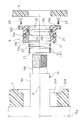
【解決手段】ポンプ軸15を摺動可能に支持する軸受機構Bをポンプフランジ4に着脱可能に支持するに、ポンプ軸15に外嵌するリング状で冷却手段Rを有する滑り軸受21とシールリング22とが装備されるカセット体19を、これがポンプフランジ4に対する連結板17側への取外しが行える状態でポンプフランジ4に取付ける。冷却手段Rは、滑り軸受21の外周部21Bに形成される複数の周方向溝37で構成される。
【選択図】図5
Description
往復動ポンプAは、図1〜図4に示すように、ベローズポンプの一対を背中合わせ状態で合体させたような構造のものであり、単位時間当たりの吐出量を大きく取れる大容量ポンプである。往復動ポンプAは、PTFE(フッ素樹脂)等の合成樹脂で成る左右中央のポンプボディ1、ポンプボディ1の左右に配されるPTFE等の合成樹脂で成る一対のベローズ(隔膜の一例)2,2、一対のエアシリンダ3,3、PP(ポリプロピレン)等の合成樹脂で成る一対のポンプフランジ4,4、計4本の通しボルト・ナット5、一対の筒状スペーサ6,6、一対のエンドカバー7,7、ポンプボディ1に外嵌されるセンターカバー16等を有して構成されている。尚、図4は、エンドカバー7を外して見た状態の側面図である。
放熱手段Hを形成する表面積の増大構成としては、外周部27Bを斜めに横切る溝を複数形成するとか、軸心X方向に貫通する孔を形成するといった構造でも良い。また、冷却手段Rは、ポンプ軸15の軸方向に延びる溝を複数設けるといった構成でも良い。
2 隔膜
2a 厚肉フランジ部
2b 蛇腹部
2c 先端厚肉板部
4 ポンプフランジ
8 密閉空間
12 吸込路
13 吐出路
15 ポンプ軸
15B 貫通突出部
16 連結ボデイ
17 連結板
18 連結棒
19 カセット体
21 滑り軸受
22 シールリング
27 摺動軸受
28 切れ込み
34 溝
37 周方向溝
A 往復動ポンプ
B 軸受機構
H 放熱手段
R 冷却手段
X 連結棒の軸心
Claims (6)
- 被移送流体の吸込路及び吐出路を備えたポンプボティと、前記ポンプボティの両端部のそれぞれに気密に固定されて前記ポンプボティとの間に密閉空間をそれぞれ形成するように対向配備される一対の隔膜と、前記各隔膜の先端部に取付けられるポンプ軸と、前記各ポンプ軸を摺動移動可能に支持するとともに前記隔膜の外側に配される連結ボデイを介して前記ポンプボティに一体化される一対のポンプフランジと、前記各ポンプ軸における前記ポンプフランジから外側に突出している貫通突出部に取付けられる連結板どうしを、前記各ポンプフランジを貫通して前記隔膜の外側に配される状態で連結する連結棒と、を有するとともに、
前記連結棒が放熱手段を有する摺動軸受を介して前記各ポンプフランジに摺動移動可能に支持されている往復動ポンプ。 - 前記放熱手段が、前記摺動軸受における前記ポンプフランジに内嵌される外周部に前記連結棒の移動方向に沿って延びる状態で形成される複数の溝によって構成されている請求項1に記載の往復動ポンプ。
- 前記摺動軸受が、断面が円形の前記連結棒に外嵌し、かつ、前記連結棒の軸心方向に沿う切れ込みが形成されて断面がC字状を呈するスリット付円筒状のものに形成されている請求項1又は2に記載の往復動ポンプ。
- 前記ポンプ軸を摺動可能に支持する軸受機構を前記ポンプフランジに着脱可能に支持するに、前記ポンプ軸に外嵌するリング状で冷却手段を有する滑り軸受とシールリングとが装備されるカセット体を、これが前記ポンプフランジに対する前記連結板側への取外しが行える状態で前記ポンプフランジに取付けられている請求項1〜3の何れか一項に記載の往復動ポンプ。
- 前記冷却手段が、前記滑り軸受における前記カセット体に内嵌される外周部に形成される複数の周方向溝によって構成されている請求項4に記載の往復動ポンプ。
- 前記隔膜が、前記ポンプボディに取付けられる厚肉フランジ部と、前記ポンプ軸の根元側に取付けられる先端厚肉板部と、前記厚肉フランジ部と前記先端厚肉板部とに亘る状態で形成される蛇腹部と、を有するベローズに構成されている請求項1〜5の何れか一項に記載の往復動ポンプ。
Priority Applications (1)
| Application Number | Priority Date | Filing Date | Title |
|---|---|---|---|
| JP2008161537A JP4677472B2 (ja) | 2008-06-20 | 2008-06-20 | 往復動ポンプ |
Applications Claiming Priority (1)
| Application Number | Priority Date | Filing Date | Title |
|---|---|---|---|
| JP2008161537A JP4677472B2 (ja) | 2008-06-20 | 2008-06-20 | 往復動ポンプ |
Publications (2)
| Publication Number | Publication Date |
|---|---|
| JP2010001808A true JP2010001808A (ja) | 2010-01-07 |
| JP4677472B2 JP4677472B2 (ja) | 2011-04-27 |
Family
ID=41583724
Family Applications (1)
| Application Number | Title | Priority Date | Filing Date |
|---|---|---|---|
| JP2008161537A Active JP4677472B2 (ja) | 2008-06-20 | 2008-06-20 | 往復動ポンプ |
Country Status (1)
| Country | Link |
|---|---|
| JP (1) | JP4677472B2 (ja) |
Families Citing this family (1)
| Publication number | Priority date | Publication date | Assignee | Title |
|---|---|---|---|---|
| CN102926992B (zh) * | 2012-11-20 | 2015-07-29 | 云南大红山管道有限公司 | 一种活塞隔膜泵活塞杆分离装置及活塞隔膜泵 |
-
2008
- 2008-06-20 JP JP2008161537A patent/JP4677472B2/ja active Active
Also Published As
| Publication number | Publication date |
|---|---|
| JP4677472B2 (ja) | 2011-04-27 |
Similar Documents
| Publication | Publication Date | Title |
|---|---|---|
| JP4644697B2 (ja) | 往復動ポンプ | |
| US3809506A (en) | Hermetically sealed pump | |
| US3207080A (en) | Balanced pressure pump | |
| US4181477A (en) | Pump valve | |
| JP6388884B2 (ja) | 2点シール及びフローティングダイアフラムウェブを備えたダイアフラムバルブ | |
| US2407792A (en) | Diaphragm pump | |
| CN2623907Y (zh) | 双联往复式隔膜泵 | |
| TW201410976A (zh) | 伸縮泵 | |
| JP4677472B2 (ja) | 往復動ポンプ | |
| WO2020191732A1 (zh) | 农业植保机及其隔膜泵 | |
| JP2005023789A (ja) | 可撓性隔膜を備えたベローズポンプ | |
| JP6145392B2 (ja) | ダイヤフラムポンプ | |
| JP5248267B2 (ja) | ポンプ | |
| JPH11324925A (ja) | エア駆動ベローズポンプ | |
| JP2016537563A (ja) | ダイアフラムカートリッジ及びダイアフラムカートリッジを有するポンプ | |
| KR101342001B1 (ko) | 공압식 자동 피스톤 펌프 | |
| CN111350714A (zh) | 一种流体做动装置 | |
| CN114320844B (zh) | 一种流量控制的可调式隔膜泵 | |
| WO2020191730A1 (zh) | 泵装置及农业植保机 | |
| JP2015218733A (ja) | 多重効用式圧送ダイアフラムポンプ | |
| JP2015021485A (ja) | 手押しポンプ | |
| CN221003338U (zh) | 新型强压三片整体式多路阀 | |
| CN117685206A (zh) | 膜头结构及液驱隔膜式压缩机系统 | |
| US11035352B2 (en) | Method and system for enhancing performance in a reciprocating compressor | |
| CN216691383U (zh) | 一种双缸气泵机座 |
Legal Events
| Date | Code | Title | Description |
|---|---|---|---|
| TRDD | Decision of grant or rejection written | ||
| A977 | Report on retrieval |
Free format text: JAPANESE INTERMEDIATE CODE: A971007 Effective date: 20110120 |
|
| A01 | Written decision to grant a patent or to grant a registration (utility model) |
Free format text: JAPANESE INTERMEDIATE CODE: A01 Effective date: 20110125 |
|
| A01 | Written decision to grant a patent or to grant a registration (utility model) |
Free format text: JAPANESE INTERMEDIATE CODE: A01 |
|
| A61 | First payment of annual fees (during grant procedure) |
Free format text: JAPANESE INTERMEDIATE CODE: A61 Effective date: 20110131 |
|
| FPAY | Renewal fee payment (event date is renewal date of database) |
Free format text: PAYMENT UNTIL: 20140204 Year of fee payment: 3 |
|
| R150 | Certificate of patent or registration of utility model |
Free format text: JAPANESE INTERMEDIATE CODE: R150 Ref document number: 4677472 Country of ref document: JP Free format text: JAPANESE INTERMEDIATE CODE: R150 |
|
| S533 | Written request for registration of change of name |
Free format text: JAPANESE INTERMEDIATE CODE: R313533 |
|
| R360 | Written notification for declining of transfer of rights |
Free format text: JAPANESE INTERMEDIATE CODE: R360 |
|
| R360 | Written notification for declining of transfer of rights |
Free format text: JAPANESE INTERMEDIATE CODE: R360 |
|
| R371 | Transfer withdrawn |
Free format text: JAPANESE INTERMEDIATE CODE: R371 |
|
| S531 | Written request for registration of change of domicile |
Free format text: JAPANESE INTERMEDIATE CODE: R313531 |
|
| S533 | Written request for registration of change of name |
Free format text: JAPANESE INTERMEDIATE CODE: R313533 |
|
| R350 | Written notification of registration of transfer |
Free format text: JAPANESE INTERMEDIATE CODE: R350 |