JP2010001662A - Construction joint frame member - Google Patents
Construction joint frame member Download PDFInfo
- Publication number
- JP2010001662A JP2010001662A JP2008161808A JP2008161808A JP2010001662A JP 2010001662 A JP2010001662 A JP 2010001662A JP 2008161808 A JP2008161808 A JP 2008161808A JP 2008161808 A JP2008161808 A JP 2008161808A JP 2010001662 A JP2010001662 A JP 2010001662A
- Authority
- JP
- Japan
- Prior art keywords
- joining
- frame material
- concrete
- frame member
- easily peelable
- Prior art date
- Legal status (The legal status is an assumption and is not a legal conclusion. Google has not performed a legal analysis and makes no representation as to the accuracy of the status listed.)
- Granted
Links
Images


Abstract
Description
本発明は、コンクリート建築における床スラブ部分のコンクリート打継工程に用いられる打継枠材に関する。 The present invention relates to a joining frame material used in a concrete joining process of a floor slab portion in a concrete building.
近年、建築技術の発展により建造される建築物は大型化し、それにともない各階ごとの床面積も広くなる傾向にある。そのため、床スラブ部分のコンクリート打設工程を複数回に分けて施工する打継工法の実施が必要とされている。
従来から用いられてきた打継工法にはラス工法があり、金属製フェンス等が打継部の枠材に用いられている。
In recent years, buildings constructed by the development of building technology have become larger in size, and the floor area of each floor tends to increase accordingly. Therefore, it is necessary to carry out a joining method in which the concrete placing process for the floor slab part is divided into a plurality of times.
Conventionally, there is a lath method as a joining method, and a metal fence or the like is used as a frame material for the joining part.
しかし、従来の打継部に用いられる枠材(以下従来型枠材とする)は、強度は高い一方で金属が用いられているため重量が重く、打継部に沿って多数設置するには施工に時間がかかっていた。また、床スラブを補強するために配置されている鉄筋との干渉を避けながら従来型枠材を固定するためには施工手順も煩雑であるという問題があった。
また、従来型枠材を用いた打継面は平坦性に乏しく、そのままコンクリートを打継すると打継目内に気泡が残る原因ともなるため、高圧水流等による打継面の平坦化処理が必要な場合があった。
また、従来技術では、打設したコンクリートを硬化させている間に打継面のコンクリートが露出した状態であるため、打継面への異物等の附着によって打継部のコンクリートの劣化が促進される懸念もあった。
さらに、従来型枠材に用いられる金属製フェンス等はコストが高いという問題が生じていた。
上記のような課題から軽量で施工の容易な打継部に用いられる枠材が強く望まれていた。
なお、打継目とは打継工程によって形成されるコンクリートとコンクリートとの接触部分のことを、打継面とは打継工程で形成されるコンクリートの略鉛直面を指す。
However, the frame material used for the conventional joining part (hereinafter referred to as the conventional type frame material) is high in strength but has a heavy weight because of the use of metal. Construction took a long time. In addition, there is a problem that the construction procedure is complicated in order to fix the conventional frame material while avoiding interference with reinforcing bars arranged to reinforce the floor slab.
In addition, the joint surface using the conventional frame material is poor in flatness, and if the concrete is cast as it is, it may cause bubbles to remain in the joint, so that it is necessary to flatten the joint surface by high-pressure water flow or the like. There was a case.
In the prior art, since the concrete on the joining surface is exposed while the placed concrete is cured, deterioration of the concrete on the joining portion is promoted by the attachment of foreign matter to the joining surface. There were also concerns.
Furthermore, the metal fence used for the conventional frame material has a problem of high cost.
From the above problems, there has been a strong demand for a frame material used for a joining portion that is lightweight and easy to construct.
Note that the joint is a contact portion between the concrete and the concrete formed by the joint process, and the joint surface is a substantially vertical surface of the concrete formed by the joint process.
本発明は、前記課題を解決するためになされたもので、床スラブ部分の打継部に使用される打継枠材である。 This invention is made | formed in order to solve the said subject, and is a joining frame material used for the joining part of a floor slab part.
打継枠材は、圧延加工又は延伸加工により表面平滑化された樹脂フィルムからなる有底箱型状に形成されコンクリートと容易に剥離し得る易剥離性包容体と、該易剥離性包容体に包容され柱体に形成された多孔質弾性体とからなり、前記易剥離性包容体上部であって多孔質弾性体上面より上方に指を係止することが可能な持手部が設けられていることを特徴とする。 The joining frame material is formed in a bottomed box shape made of a resin film whose surface is smoothed by rolling or stretching, and an easily peelable container that can be easily peeled off from concrete. A porous elastic body encapsulated and formed in a columnar body, provided with a handle portion which is an upper part of the easily peelable enclosure and capable of locking a finger above the upper surface of the porous elastic body It is characterized by being.
本願打継枠材は打継工程終了後に打継部から除去されるが、除去された打継枠材は別の打継工程において繰り返し用いてもよい。 Although the joining frame material of the present application is removed from the joining portion after the joining process is completed, the removed joining frame material may be repeatedly used in another joining process.
易剥離性包容体がコンクリートと容易に剥離しうるとは、打継工程施工によるコンクリート硬化後1日以内に行う打継枠材の打継部からの除去作業において、打継枠材に設けられた持手部に指を係止すると共に易剥離性包容体を掴んだ後、打継枠材を上方へ引き抜きながら除去作業を行った際に、当該除去作業が打継枠材にとって打継工程へ用いられた回数が少なくとも一回目である場合には、易剥離性包容体が、多孔質弾性体上面の高さより下部分の易剥離性包容体の表面積の5分の1以上を欠損しかつ該欠損により欠落した部分をコンクリートの打継面に附着残存させる事なく、コンクリートから剥離されることを言う。 An easily peelable inclusion can be easily peeled off from concrete when it is removed from the joining part of the joining frame material within one day after the concrete is hardened by the joining process construction. After holding the finger to the handle part and grasping the easily peelable container, the removal work is performed for the joining frame material when the removal work is performed while pulling the joining frame material upward. When the number of times used in the above is at least the first time, the easily peelable enclosure lacks one fifth or more of the surface area of the easily peelable container below the height of the upper surface of the porous elastic body, and It means that a portion missing due to the defect is peeled off from the concrete without remaining attached to the joint surface of the concrete.
易剥離性包容体は圧延加工又は延伸加工により表面平滑化された樹脂フィルムからなる有底箱型状に形成されたものであり、前記多孔質弾性体を内包して配置される。易剥離性包容体は、コンクリートとの密着性を低減するために、打継枠材配設時に易剥離性包容体表面にしわを発生させずに配設できることが好ましいことから、易剥離性包容体底面積が多孔質弾性体底面積よりも1%〜10%大きいことが好ましい。また、易剥離性包容体の高さは少なくとも内包する多孔質弾性体の高さ以上であることが好ましく、より好ましくは多孔質弾性体を易剥離性包容体が内包したときに、多孔質弾性体上面より上方に50mm〜200mm上回る高さに設定するのが良い。 The easily peelable enclosure is formed in a bottomed box shape made of a resin film whose surface is smoothed by rolling or stretching, and is disposed so as to enclose the porous elastic body. In order to reduce the adhesion to concrete, the easily peelable enclosure is preferably capable of being disposed without generating wrinkles on the surface of the easily peelable container when the joining frame material is disposed. The body bottom area is preferably 1% to 10% larger than the porous elastic body bottom area. In addition, the height of the easily peelable enclosure is preferably at least the height of the encapsulating porous elastic body, and more preferably when the easily peelable enclosure encloses the porous elastic body, It is preferable to set the height above the body upper surface by 50 mm to 200 mm.
易剥離性包容体に用いられる樹脂フィルムはポリエチレンからなるものが最も好ましいが、ポリプロピレン、軟質塩化ビニル、PET、ナイロンまたはビニロンからなるものでもよい。 The resin film used for the easily peelable inclusion is most preferably made of polyethylene, but may be made of polypropylene, soft vinyl chloride, PET, nylon or vinylon.
易剥離性包容体には、延伸加工又は圧延加工(この段落において加工という)され表面が平滑化された前記樹脂フィルムからなるものを用いているので、打継枠材とコンクリートとの密着性を小さくすることができ、打継枠材の打継面からの剥離除去を容易に行うことができる。
前記樹脂フィルムがポリエチレンからなる易剥離性包容体である場合は摂氏140度〜190度で加熱しながら加工され、ポリプロピレンからなる易剥離性包容体である場合は摂氏90度〜150度で加熱しながら加工され、軟質塩化ビニルからなる易剥離性包容体である場合は摂氏150度〜180度で加熱しながら加工された樹脂フィルムからなることが好ましい。
ここで、延伸加工としては樹脂を一対のロールの間隙から引き抜いて、一軸方向に延伸する延伸加工方法であることが好ましい。圧延加工としては樹脂を一対のロールの間隙を挿通させて、加圧薄膜化する圧延加工方法であることが好ましい。
Since the easily peelable packaging is made of the resin film having a smoothed surface that has been stretched or rolled (called processing in this paragraph), the adhesion between the joining frame material and the concrete is improved. It can be made small, and peeling and removal from the joining surface of the joining frame material can be easily performed.
When the resin film is an easily peelable enclosure made of polyethylene, it is processed while heating at 140 to 190 degrees Celsius, and when it is an easily peelable enclosure made of polypropylene, it is heated at 90 to 150 degrees Celsius. However, in the case of an easily peelable inclusion made of soft vinyl chloride, it is preferably made of a resin film processed while heating at 150 to 180 degrees Celsius.
Here, the stretching process is preferably a stretching process method in which the resin is drawn from the gap between the pair of rolls and stretched in a uniaxial direction. The rolling process is preferably a rolling process method in which a resin is inserted through a gap between a pair of rolls to form a pressure thin film.
また、易剥離性包容体は延伸加工又は加熱圧延加工により表面粗さがRa=3μm〜10μmとなるように表面の平滑化がおこなわれていることがより好ましい。このような平滑化が行われることにより打継面のコンクリートとの密着性をより小さく保つことができ、易剥離性包容体の剥離除去を容易に行うことができる。
一方、Raが3μm以下とするのは加工精度に高度な技術が必要であるのでコストを低く抑えることができない。また、Raが10μm以上の場合は易剥離性包容体とコンクリートとの密着性が高くなる場合があり、易剥離性包容体の剥離除去作業時の耐久性が十分確保できず作業性を損なう場合がある。
Moreover, it is more preferable that the surface of the easily peelable inclusion body is smoothed by stretching or heat rolling so that the surface roughness is Ra = 3 μm to 10 μm. By performing such smoothing, it is possible to keep the adhesion of the joining surface with the concrete smaller, and it is possible to easily remove and remove the easily peelable enclosure.
On the other hand, when Ra is set to 3 μm or less, a high level of technology is required for processing accuracy, so the cost cannot be kept low. In addition, when Ra is 10 μm or more, the adhesion between the easily peelable enclosure and the concrete may be high, and the durability at the time of removing and removing the easily peelable enclosure cannot be secured sufficiently, thereby impairing the workability. There is.
易剥離性包容体の厚さは0.08mm〜0.2mmであることが好ましく、より好ましくは厚さ0.1mmであることが望ましい。易剥離性包容体の厚さが0.08mmよりも薄い場合は打継枠材を除去する際に易剥離性包容体の強度が十分でなく、破損し易い。易剥離性包容体の厚さが0.2mmよりも厚い場合は製造コストが高くなり好ましくない。 The thickness of the easily peelable container is preferably 0.08 mm to 0.2 mm, more preferably 0.1 mm. When the thickness of the easily peelable container is thinner than 0.08 mm, the strength of the easily peelable container is not sufficient when the joining frame material is removed, and is easily damaged. When the thickness of the easily peelable container is thicker than 0.2 mm, the production cost increases, which is not preferable.
多孔質弾性体は柱体に形成され、コンクリート厚みよりも高くなるように高さが設定されることが好ましい。 The porous elastic body is preferably formed in a columnar body and the height is set to be higher than the concrete thickness.
多孔質弾性体は柱体であればよいが、隣接する打継枠材同士の密着性およびコンクリートとの打継面の平坦性向上のために、より好ましくは四角柱体であることが望ましい。
四角柱体の多孔質弾性体を用いることで打継面の平坦性が向上すると、打継面への空気の混入が減少し、打継面のコンクリート強度の改善を図ることができる。
The porous elastic body may be a column, but a quadrangular column is more preferable in order to improve the adhesion between adjacent joining frame members and the flatness of the joining surface with concrete.
If the flatness of the joining surface is improved by using the porous elastic body of the quadrangular prism body, the mixing of air into the joining surface is reduced, and the concrete strength of the joining surface can be improved.
多孔質弾性体の底面寸法は、底面形状を内接する方形を仮定した時に、該方形の長辺が100〜150mm、短辺が50〜90mmとなる寸法であることが好ましい。 The bottom dimension of the porous elastic body is preferably a dimension such that the long side of the square is 100 to 150 mm and the short side is 50 to 90 mm, assuming a square inscribed in the shape of the bottom.
本願打継枠材は床スラブの打継工程に用いられる枠材であるが、床スラブと床スラブを打継ぐ工程に使用する場合には多孔質弾性体は高さ100mm以上250mm以下で用いることが好ましい。多孔質弾性体の高さを100mm以上とすることで、床スラブの打継工程に使用する枠材として機能しうる高さを確保することができる。多孔質弾性体の高さを250mm以下とすることで床スラブと床スラブを打継ぐ工程に使用する場合には適用可能である。
また、多孔質弾性体の高さ100mm以上250mm以下で用いるこの場合には多孔質弾性体の硬さは6kg〜11kgであることが好ましい。硬さが6kgより小さいとコンクリートからの側圧に耐えられず、流し込まれたコンクリートを止めることができない。硬さ11kgより大きいことは使用に支障はないが、多孔質弾性体の密度が高くなる場合があり、その場合には製造コストの増大につながる。
The present joining frame material is a frame material used in the floor slab joining process, but when used in the process of joining floor slabs and floor slabs, the porous elastic body should be used at a height of 100 mm to 250 mm. Is preferred. By setting the height of the porous elastic body to 100 mm or more, it is possible to ensure a height that can function as a frame material used in the floor slab joining process. When the height of the porous elastic body is set to 250 mm or less, it can be applied to the case of using the floor slab and the step of transferring the floor slab.
In this case, the hardness of the porous elastic body is preferably 6 kg to 11 kg. If the hardness is less than 6 kg, it cannot withstand the lateral pressure from the concrete and the poured concrete cannot be stopped. When the hardness is larger than 11 kg, there is no problem in use, but the density of the porous elastic body may increase, and in this case, the manufacturing cost increases.
また、あらかじめ形成された壁や柱に床スラブを打継ぐ場合には多孔質弾性体の高さは250mmより高く700mm以下で用いることが好ましい。あらかじめ形成された壁や柱はあらかじめ掘り下げられた設置箇所に設置される場合があるが、高さが250mmより高ければ打継枠材を前記掘り下げられた設置箇所に配設しても床スラブの上面よりも多孔質弾性体の上面を高くなるように配設できるからである。
多孔質弾性体の高さが250mmより高く700mm以下で用いられる場合には多孔質弾性体の硬さは12kg〜17kgであることが好ましい。打継枠材が前記掘り下げられた設置箇所に配設された場合には、床スラブと床スラブを打継ぐ工程に用いる場合よりも高い側圧に耐えるためである。
In addition, when the floor slab is cast on a previously formed wall or column, the height of the porous elastic body is preferably higher than 250 mm and lower than 700 mm. Pre-formed walls and pillars may be installed at installation sites that have been dug down in advance, but if the height is higher than 250 mm, the floor slabs can be installed even if the joining frame material is disposed at the dug-up installation site. This is because the upper surface of the porous elastic body can be disposed higher than the upper surface.
When the porous elastic body is used at a height of more than 250 mm and 700 mm or less, the hardness of the porous elastic body is preferably 12 kg to 17 kg. This is because, when the joining frame material is disposed at the installation site dug down, the floor slab and the floor slab are used in a process of joining the floor slab to withstand a higher side pressure.
本願発明は壁や柱などよりも厚みの薄い床スラブにおける打継工程に用いることを目的とするため、多孔質弾性体の高さを700mmより高くしなくても打継工程用の枠材として使用するための高さを確保することができる。また、多孔質弾性体の高さを700mm以下とすることで、従来型枠材に用いられていた金属材料を使用しなくても打設したコンクリートからの側圧に耐えられる構成を実現することができ、打継工程用の枠材として機能させることができる。 Since the present invention is intended for use in a joining process in a floor slab having a thickness smaller than that of a wall, a pillar, etc., as a frame material for a joining process even if the height of the porous elastic body is not higher than 700 mm. The height for use can be secured. Further, by setting the height of the porous elastic body to 700 mm or less, it is possible to realize a configuration that can withstand a lateral pressure from the placed concrete without using a metal material that has been used in a conventional frame material. It can function as a frame material for the joining process.
多孔質弾性体の素材は発泡性弾性樹脂からなるものが好ましく、より好ましくはウレタンからなるものがよい。またポリエステルや綿、不敷布、麻の繊維を押し固めたものからなるものでもよい。 The material of the porous elastic body is preferably made of a foamable elastic resin, more preferably made of urethane. Further, it may be made of polyester, cotton, non-woven cloth, or hemp fiber.
打継枠材を上記構成とすることにより、打継枠材の一つ当たりの重量を20g〜200gとすることができ、従来型枠材に比べて軽量化を図ることができる。 By setting the joining frame material to the above-described configuration, the weight per joining frame material can be 20 g to 200 g, and the weight can be reduced as compared with the conventional frame material.
また好ましくは、易剥離性包容体上部に持手部が設けられることが望ましい。該持手部は易剥離性包容体の上部であって多孔質弾性体上面より上方に直接形成しても良いが、下記に説明する易剥離性包容体上部を閉塞した閉塞部材に取付けられることが好ましい。より好ましくは、持手部は指を通して係止することができる直径2cm〜10cmの大きさを有する環状の持手部がよい。該環状の持手部は、下記に説明する閉塞部材である紐状結束具を挿通して用いられ、易剥離性包容体を閉塞すると同時に取付けられることが好ましい。 Moreover, it is preferable that a handle portion is provided on the easily peelable container. The handle portion may be formed directly above the upper surface of the porous elastic body and above the upper surface of the porous elastic body. However, the handle portion may be attached to a closing member that closes the upper portion of the easy peelable container described below. Is preferred. More preferably, the handle portion is an annular handle portion having a diameter of 2 cm to 10 cm that can be locked through a finger. The annular handle portion is preferably used by inserting a string-like binding tool, which is a closing member described below, and is attached at the same time as closing the easily peelable container.
また好ましくは、易剥離性包容体上部が多孔質弾性体上面より上方において閉塞部材により閉塞されることが望ましい。該閉塞部材はゴムバンド、ホチキス、金属環を用いてもよいが、樹脂、麻または木綿等で形成された紐状結束具であることが好ましく、さらに好ましくは、バンド部とバンド部の一端に設けた係止部とを備え、該係止部はバンド部を一方向にのみ挿通し逆方向には挿通できない構造とされた緩み止付紐状結束具がよい。この緩み止付紐状結束具によれば易剥離性包容体の大きさに関わらず十分強固に閉塞することができ、しかも前記環状の持手部に該緩み止付紐状結束具を挿通させることで易剥離性包容体の閉塞と同時に持手部を取付けることができる。
また、易剥離性包容体上部の閉塞は該易剥離性包容体上部の閉塞部分を溶着により閉塞させても良い。
Preferably, the upper part of the easily peelable container is closed by the closing member above the upper surface of the porous elastic body. The closing member may be a rubber band, a staple, or a metal ring, but is preferably a string-like tie formed of resin, hemp or cotton, and more preferably at the band part and one end of the band part. It is preferable to use a string-like binding tool with a loosening stop that is provided with a locking portion provided, and the locking portion has a structure in which the band portion is inserted only in one direction and cannot be inserted in the reverse direction. According to this slack-preventing string-like binding tool, it is possible to sufficiently firmly close regardless of the size of the easily peelable container, and to allow the slack-preventing string-shaped binding tool to be inserted into the annular handle portion. Thus, the handle portion can be attached simultaneously with the closing of the easily peelable container.
Moreover, you may block | close the upper part of the easily peelable container by welding the obstruct | occluded part of this easily peelable container upper part.
ここで、打継部は打継枠材と該打継枠材を支持する複数の鉄筋支持材からなる。
鉄筋支持材は水平かつ打継目を床上方向から見た線と平行に複数本配置され、それぞれ垂直方向に互いに平行になるように配置されている。打継枠材は配置された鉄筋支持材に、コンクリートを打設する側から当接するように配設されて構成される。鉄筋支持材には鉄筋を用い、通常鉄筋が施工される場合と同じく100mm〜200mm程度の間隔で配筋することができる。また、鉄筋支持材は他の床スラブ補強に使用される鉄筋と兼用されることが好ましい。
Here, the joining portion is composed of a joining frame material and a plurality of reinforcing bar supporting materials that support the joining frame material.
A plurality of reinforcing bar support members are arranged in parallel to the horizontal and joint lines seen from above the floor, and are arranged in parallel to each other in the vertical direction. The joining frame material is arranged and arranged to abut on the arranged reinforcing bar support material from the side on which the concrete is placed. Reinforcing bars are used as the reinforcing bar support material, and the reinforcing bars can be arranged at intervals of about 100 mm to 200 mm as in the case where reinforcing bars are usually constructed. Moreover, it is preferable that the reinforcing bar support material is also used as a reinforcing bar used for reinforcing other floor slabs.
本願の打継枠材によれば、金属材料を使用しなくても打設したコンクリートからの側圧に耐えることができ、打継工程用の枠材としての機能を発揮させることができる。また、従来型枠材と比較して軽量に製造できるため、打継枠材の運搬効率が向上し、打継部の施工効率の改善が図れる。 According to the joining frame material of the present application, it is possible to withstand a lateral pressure from the placed concrete without using a metal material, and it is possible to exert a function as a frame material for the joining process. Moreover, since it can manufacture lightweight compared with a conventional frame material, the conveyance efficiency of a joining frame material improves, and the improvement of the construction efficiency of a joining part can be aimed at.
また、打継枠材は樹脂フィルムからなる易剥離性包容体と該易剥離性包容体に包容された多孔質弾性体を構成の一部としていることから、容易に変形させることができる。従って、配設時に打継部に配置されている鉄筋と接触しても変形により配設阻害を回避できるため、鉄筋との干渉により配設作業が手間取ることがない。 Further, since the joining frame material includes an easily peelable container made of a resin film and a porous elastic body contained in the easily peelable container, it can be easily deformed. Therefore, even if it contacts with the reinforcing bar arranged in the joining portion at the time of arrangement, the arrangement hindrance can be avoided by deformation, so that the arrangement work is not time-consuming due to interference with the reinforcing bar.
さらに、打継枠材に持手部を設けることで、持手部に指を係止することで確実に打継枠材を確保できるため、打継枠材の除去の際に手が滑るなどによる除去作業の失敗を減らすことができ、打継枠材の除去作業も迅速に行うことができる。また、持手部を設けることで、多数の打継枠材を同時に持ち運ぶことができ、打継工程の準備もしくは片付け作業のための運搬作業も効率良く行うことができる。 Furthermore, by providing a handle on the joint frame material, it is possible to ensure the joint frame material by locking the finger to the handle part, so that the hand slips when the joint frame material is removed, etc. The failure of the removal work due to the can be reduced, and the removal work of the joining frame material can also be performed quickly. In addition, by providing the handle portion, it is possible to carry a large number of joining frame materials at the same time, and it is possible to efficiently carry out preparation work for the joining process or a tidying work.
易剥離性包容体の上部が閉塞されていれば、打継枠材を除去する際に持手部と共に該閉塞された部分を掴んで引き抜くことができるので力を込めやすく、閉塞されずに持手部が設けられた場合よりも打継枠材を除去する作業速度の向上が図れる。また、持手部と易剥離性包容体が閉塞された部分を共に掴んで引き抜くことによって、引き抜き時の力を打継枠材の全体に分散することができ、易剥離性包容体の破損を防ぐことができる。 If the upper part of the easily peelable container is closed, it is possible to grasp and pull the closed part together with the handle when removing the joining frame material. The working speed for removing the joining frame material can be improved as compared with the case where the hand portion is provided. Also, by grasping and pulling out the part where the handle and the easily peelable enclosure are closed together, the pulling force can be distributed throughout the joining frame material, and damage to the easily peelable enclosure is prevented. Can be prevented.
また、打継枠材は変形が容易であるため、打継部の支持用配筋に多少歪みがあっても隙間なく配設することができ、硬化前のコンクリートが打継部から外側に流れ出ることはない。 In addition, since the joining frame material is easy to deform, even if there is some distortion in the support reinforcement of the joining part, it can be arranged without any gaps, and the concrete before hardening flows out from the joining part. There is nothing.
さらに、コンクリートは打継枠材と密着したまま硬化し、次工程で新たにコンクリートを打設する直前に打継枠材を除去することができるので、打設したコンクリートを硬化させている間は打継面を外気に晒すことなく保護することができる。これにより、打継面への不純物の附着を防止し、施工後の打継部からコンクリートの劣化が促進されることを防ぐことができる。 In addition, the concrete hardens while being in close contact with the casting frame material, and the joining frame material can be removed immediately before placing the concrete in the next process. It is possible to protect the joint surface without exposing it to the outside air. Thereby, adhesion of impurities to the joining surface can be prevented, and deterioration of concrete from the joining portion after construction can be prevented from being promoted.
易剥離性包容体は、圧延加工又は延伸加工により表面平滑化された樹脂フィルムにより形成されているのでコンクリートとの剥離性がよく、コンクリート硬化後に打継枠材をコンクリートから容易に剥離除去することができ、除去作業を短時間に行うことができるとともに易剥離性包容体の破損を防ぐことができる。 Easy peelable inclusions are formed from a resin film whose surface has been smoothed by rolling or stretching, so that the peelability from the concrete is good, and the joint frame material can be easily peeled and removed from the concrete after the concrete has hardened. The removal operation can be performed in a short time and the easily peelable enclosure can be prevented from being damaged.
以下、本発明の打継枠材について、実施例に基づきさらに詳細に説明する。
図1において、打継枠材1は多孔質弾性体2と、多孔質弾性体2を包容する易剥離性包容体3より構成されている。
また、易剥離性包容体3はその上部であって多孔質弾性体2上面より上方が閉塞部材4により閉塞されており、該閉塞された部分には閉塞部材4が挿通された環状の持手部5が設けられている。
Hereinafter, the joint frame material of the present invention will be described in more detail based on examples.
In FIG. 1, the joining frame material 1 is composed of a porous
Further, the easily
本実施例において、多孔質弾性体2には四角柱体のウレタン素材のものを用いた。また、易剥離性包容体3には厚さ0.1mmのポリエチレン素材を用い、易剥離性包容体3上部を閉塞する閉塞部材4にはプラスチック樹脂製の緩み止付紐状結束バンドを用い、持手部5にはプラスチック樹脂製の環状の持手部を用いた。
In the present embodiment, the porous
なお、本願打継枠材は図7に示すように、多孔質弾性体12と、多孔質弾性体12が易剥離性包容体13に包容され、持手部14は易剥離性包容体13の上部であって多孔質弾性体12上面よりも上方部分に直接環状に設けられた構造とする打継枠材11であってもよく、該打継枠材11を以下に説明する実施例において打継枠材1の代わりに用いることができる。
In addition, as shown in FIG. The joining frame material 11 may be an upper portion and a structure provided in an annular shape directly above the upper surface of the porous
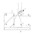
図2は打継枠材1を用いて構成された打継部6の俯瞰図である。打継部6は打継枠材1と該打継枠材1が当接する鉄筋支持材7からなる。鉄筋支持材7は水平かつ打継目を床上方向から見た線と平行に複数本配置され、かつ、垂直方向に互いに平行になるように配置されている。打継枠材1の打継部6への配設には特別な工具を用いる必要はなく、図2に示すように鉄筋支持材7にコンクリートを打設する側(図2では図に向かって左上方向)から当接するように配設すればよい。ここで、打継枠材1底面が底部型枠8上面に当接するように配設する。
なお、鉄筋支持材7は床スラブの補強に使用される他の鉄筋と兼用できるため、鉄筋支持材7を用いるために特別にコストや作業手順が増大することはない。
FIG. 2 is a bird's-eye view of the joining
Since the reinforcing
本実施例では打継枠材1は垂直方向に2列配置された鉄筋支持材7に当接するように設置され、打継面と平行に少なくとも2個以上の打継枠材1が互いに密着して配設されている。
In this embodiment, the joining frame members 1 are installed so as to contact the reinforcing
図3に、打継枠材1を配設し、床スラブであるコンクリート9を打設した後の打継部6の横断面図を示す。
打継枠材1は鉄筋支持材7によって支えられているので、コンクリート9から側圧を受けても打継枠材1の並びが乱れることはない。また、打継枠材1はコンクリート9と密着することができるので、打継面10が外気に露出することがない。従ってコンクリート9が硬化して打継枠材1が除去されるまで打継面10への不純物の附着を防止し、施工後に床スラブの劣化が打継目から促進されることを防ぐことができる。
また、多孔質弾性体2が四角柱体であるため打継面10が平坦に形成されるので、打継面の平坦化処理を行わなくても打継後の打継目内に残存する気泡を低減することができる。
FIG. 3 shows a cross-sectional view of the joining
Since the joining frame material 1 is supported by the reinforcing
Further, since the joining
コンクリート9が硬化した後、打継枠材1を除去する。除去作業は、図4に示すように易剥離性包容体3の持手部5に指を係止して、もしくは持手部5に指を係止すると共に易剥離性包容体3を掴み、上方へ引き抜けばよい。
After the
なお、コンクリート9が硬化した後も打継枠材1を1日以上放置したような場合には、打継枠材1とコンクリート9との密着が進み、上記のような方法で打継枠材1を除去することが困難な場合がある。
このような場合の打継枠材1の除去手順は次のように行う。まず、図5に示すように易剥離性包容体3の上部を開放した後、易剥離性包容体3から多孔質弾性体2を抜き取り、次に図6に示すように易剥離性包容体3を掴んでコンクリート9から剥離除去する。
このような除去方法を用いれば、コンクリート打継枠材が強く密着した場合でも少なくとも多孔質弾性体をリサイクルすることができ経済的である。
In addition, when the joining frame material 1 is left for one day or more after the
The removal procedure of the joining frame material 1 in such a case is performed as follows. First, after opening the upper part of the easily
If such a removal method is used, even when the concrete joining frame material is strongly adhered, at least the porous elastic body can be recycled, which is economical.
1 打継枠材
2 多孔質弾性体
3 易剥離性包容体
4 閉塞部材
5 持手部
6 打継部
7 鉄筋支持材
8 底部型枠
9 コンクリート
10 打継面
DESCRIPTION OF SYMBOLS 1
Claims (2)
前記打継枠材は、圧延加工又は延伸加工により表面平滑化された樹脂フィルムからなる有底箱型状に形成されコンクリートと容易に剥離し得る易剥離性包容体と、該易剥離性包容体に包容され柱体に形成された多孔質弾性体とからなり、
前記易剥離性包容体上部であって多孔質弾性体上面より上方に指を係止することが可能な持手部が設けられていること
を特徴とした打継枠材。 A joining frame material used in the concrete joining process of the floor slab part,
The joint frame material is formed in a bottomed box shape made of a resin film whose surface has been smoothed by rolling or stretching, and an easily peelable container that can be easily peeled off from concrete, and the easily peelable container Composed of a porous elastic body formed into a columnar body,
A joining frame material, characterized in that a grip portion capable of locking a finger is provided above the easily peelable enclosure and above the upper surface of the porous elastic body.
閉塞部材に指を係止可能な持手部が設けられること
を特徴とした請求項1に記載の打継枠材。 The upper part of the easily peelable enclosure is closed by a closing member above the upper surface of the porous elastic body,
The joint frame material according to claim 1, wherein a grip portion capable of locking a finger to the closing member is provided.
Priority Applications (1)
| Application Number | Priority Date | Filing Date | Title |
|---|---|---|---|
| JP2008161808A JP5314334B2 (en) | 2008-06-20 | 2008-06-20 | Joint frame material |
Applications Claiming Priority (1)
| Application Number | Priority Date | Filing Date | Title |
|---|---|---|---|
| JP2008161808A JP5314334B2 (en) | 2008-06-20 | 2008-06-20 | Joint frame material |
Publications (2)
| Publication Number | Publication Date |
|---|---|
| JP2010001662A true JP2010001662A (en) | 2010-01-07 |
| JP5314334B2 JP5314334B2 (en) | 2013-10-16 |
Family
ID=41583590
Family Applications (1)
| Application Number | Title | Priority Date | Filing Date |
|---|---|---|---|
| JP2008161808A Active JP5314334B2 (en) | 2008-06-20 | 2008-06-20 | Joint frame material |
Country Status (1)
| Country | Link |
|---|---|
| JP (1) | JP5314334B2 (en) |
Cited By (1)
| Publication number | Priority date | Publication date | Assignee | Title |
|---|---|---|---|---|
| JP6017718B1 (en) * | 2016-02-19 | 2016-11-02 | 武士 廣瀬 | Concrete joint frame material |
Families Citing this family (1)
| Publication number | Priority date | Publication date | Assignee | Title |
|---|---|---|---|---|
| JP6159899B1 (en) * | 2017-02-22 | 2017-07-05 | 東邦アストリー株式会社 | Concrete joint spacer |
Citations (3)
| Publication number | Priority date | Publication date | Assignee | Title |
|---|---|---|---|---|
| JPS54128817U (en) * | 1978-02-25 | 1979-09-07 | ||
| JPH06312750A (en) * | 1993-04-26 | 1994-11-08 | Daiwa Houzai Kk | Bag for packing |
| JP2007085148A (en) * | 2005-09-22 | 2007-04-05 | Kyoto Supeesaa:Kk | Concrete stopping sponge |
-
2008
- 2008-06-20 JP JP2008161808A patent/JP5314334B2/en active Active
Patent Citations (3)
| Publication number | Priority date | Publication date | Assignee | Title |
|---|---|---|---|---|
| JPS54128817U (en) * | 1978-02-25 | 1979-09-07 | ||
| JPH06312750A (en) * | 1993-04-26 | 1994-11-08 | Daiwa Houzai Kk | Bag for packing |
| JP2007085148A (en) * | 2005-09-22 | 2007-04-05 | Kyoto Supeesaa:Kk | Concrete stopping sponge |
Cited By (1)
| Publication number | Priority date | Publication date | Assignee | Title |
|---|---|---|---|---|
| JP6017718B1 (en) * | 2016-02-19 | 2016-11-02 | 武士 廣瀬 | Concrete joint frame material |
Also Published As
| Publication number | Publication date |
|---|---|
| JP5314334B2 (en) | 2013-10-16 |
Similar Documents
| Publication | Publication Date | Title |
|---|---|---|
| CN104989102B (en) | A kind of improved concrete walls, column construction method | |
| CN103556819B (en) | A kind of construction method of reserved constructional column hole on beam slab | |
| CN104196231A (en) | Concrete floor aluminum alloy template and construction method thereof | |
| CN105952154B (en) | A kind of concrete-pouring template stent | |
| JP5314334B2 (en) | Joint frame material | |
| JP2011026777A (en) | Pneumatic form | |
| CN211007659U (en) | Device for controlling forming of embedded steel plate in concrete column on column surface | |
| CN110284729A (en) | A kind of historical building wall sectional type cutting disassembling method | |
| CN103452319A (en) | Chiseling-free device for concrete splicing interface and construction method for chiseling-free device | |
| CN105604339B (en) | Secondary structure constructs column reinforcing method | |
| CN203270595U (en) | Independent foundation construction inner formwork device with cup rabbet smaller than 600mm*600mm | |
| JP2010105380A (en) | Form for precast concrete and method for manufacturing precast concrete member | |
| KR101759199B1 (en) | A form bringing out stripping and deck plate using the form | |
| CN109853948A (en) | The integrated template system and mold method of the cast-in-place overhanging windowsill of secondary structure | |
| JP2010024785A (en) | Concrete curing sheet, its manufacturing method, and concrete wet-curing method using the curing sheet | |
| JP6017718B1 (en) | Concrete joint frame material | |
| JP5309797B2 (en) | Beam formwork unit, beam formwork support method, column beam frame construction method, column beam frame | |
| KR20160027360A (en) | Construction method for outside insulating concrete structure | |
| JP2000027438A (en) | Method for vertically jointing concrete horizontal member | |
| CN202644998U (en) | Wall concrete formwork fixing device | |
| JPH0825338A (en) | Manufacture of hollow pc beam | |
| CN209163445U (en) | A kind of wafer board parting seam block structure | |
| JP2003336315A (en) | Reinforced concrete beam structure | |
| CN208137275U (en) | One kind exempting from template iron net concrete casting beam, column | |
| JP2009275432A (en) | Joint structure of steel frame beam and reinforced concrete column |
Legal Events
| Date | Code | Title | Description |
|---|---|---|---|
| A621 | Written request for application examination |
Free format text: JAPANESE INTERMEDIATE CODE: A621 Effective date: 20110620 |
|
| A131 | Notification of reasons for refusal |
Free format text: JAPANESE INTERMEDIATE CODE: A131 Effective date: 20120918 |
|
| A521 | Request for written amendment filed |
Free format text: JAPANESE INTERMEDIATE CODE: A523 Effective date: 20121119 |
|
| TRDD | Decision of grant or rejection written | ||
| A01 | Written decision to grant a patent or to grant a registration (utility model) |
Free format text: JAPANESE INTERMEDIATE CODE: A01 Effective date: 20130618 |
|
| A61 | First payment of annual fees (during grant procedure) |
Free format text: JAPANESE INTERMEDIATE CODE: A61 Effective date: 20130705 |
|
| R150 | Certificate of patent or registration of utility model |
Free format text: JAPANESE INTERMEDIATE CODE: R150 Ref document number: 5314334 Country of ref document: JP Free format text: JAPANESE INTERMEDIATE CODE: R150 |
|
| R250 | Receipt of annual fees |
Free format text: JAPANESE INTERMEDIATE CODE: R250 |
|
| R250 | Receipt of annual fees |
Free format text: JAPANESE INTERMEDIATE CODE: R250 |
|
| R250 | Receipt of annual fees |
Free format text: JAPANESE INTERMEDIATE CODE: R250 |
|
| R250 | Receipt of annual fees |
Free format text: JAPANESE INTERMEDIATE CODE: R250 |
|
| R250 | Receipt of annual fees |
Free format text: JAPANESE INTERMEDIATE CODE: R250 |
|
| R250 | Receipt of annual fees |
Free format text: JAPANESE INTERMEDIATE CODE: R250 |
|
| R250 | Receipt of annual fees |
Free format text: JAPANESE INTERMEDIATE CODE: R250 |
|
| R250 | Receipt of annual fees |
Free format text: JAPANESE INTERMEDIATE CODE: R250 |