JP2010000993A - Pneumatic tire - Google Patents
Pneumatic tire Download PDFInfo
- Publication number
- JP2010000993A JP2010000993A JP2008163689A JP2008163689A JP2010000993A JP 2010000993 A JP2010000993 A JP 2010000993A JP 2008163689 A JP2008163689 A JP 2008163689A JP 2008163689 A JP2008163689 A JP 2008163689A JP 2010000993 A JP2010000993 A JP 2010000993A
- Authority
- JP
- Japan
- Prior art keywords
- layer
- tire
- carcass
- rubber layer
- pneumatic tire
- Prior art date
- Legal status (The legal status is an assumption and is not a legal conclusion. Google has not performed a legal analysis and makes no representation as to the accuracy of the status listed.)
- Granted
Links
Images
Abstract
Description
本発明は、トレッド部に有機繊維コードからなるベルト層を配置した空気入りタイヤに関し、更に詳しくは、操縦安定性の低下を回避しつつ、乗り心地を向上することを可能にした空気入りタイヤに関する。 The present invention relates to a pneumatic tire in which a belt layer made of an organic fiber cord is disposed in a tread portion. More specifically, the present invention relates to a pneumatic tire that can improve riding comfort while avoiding a decrease in steering stability. .
従来、空気入りタイヤにおいて、乗り心地の向上や軽量化を目的として、スチールコードからなるベルト層の替わりに、アラミド等の有機繊維コードからなるベルト層を使用することが提案されている(例えば、特許文献1〜3参照)。 Conventionally, in pneumatic tires, it has been proposed to use a belt layer made of an organic fiber cord such as aramid instead of a belt layer made of steel cord for the purpose of improving riding comfort and reducing the weight (for example, Patent Literatures 1 to 3).
しかしながら、有機繊維コードからなるベルト層はスチールコードからなるベルト層に比べて面外曲げ剛性が低いため、トレッド部に有機繊維コードからなるベルト層を配置した場合、高負荷条件でのコーナリング時にトレッド面の一部に浮き上がりを生じ、接地面積の減少により操縦安定性が低下するという問題がある。
本発明の目的は、操縦安定性の低下を回避しつつ、乗り心地を向上することを可能にした空気入りタイヤを提供することにある。 An object of the present invention is to provide a pneumatic tire that can improve ride comfort while avoiding a decrease in steering stability.
上記目的を達成するための本発明の空気入りタイヤは、一対のビード部間に複数層のカーカス層を装架すると共に、サイドウォール部のタイヤ最大幅位置での総厚さを5mm〜8mmとした空気入りタイヤにおいて、トレッド部における前記カーカス層の外周側にタイヤ周方向に対して傾斜する複数本の有機繊維コードからなる少なくとも1層のベルト層を配置し、該ベルト層のタイヤ径方向内側位置において前記カーカス層の層間に補強ゴム層を配置したことを特徴とするものである。 In order to achieve the above object, the pneumatic tire of the present invention has a plurality of carcass layers mounted between a pair of bead portions, and the total thickness of the sidewall portions at the tire maximum width position is 5 mm to 8 mm. In the pneumatic tire, at least one belt layer made of a plurality of organic fiber cords inclined with respect to the tire circumferential direction is disposed on the outer peripheral side of the carcass layer in the tread portion, and the inner side in the tire radial direction of the belt layer A reinforcing rubber layer is disposed between the carcass layers at a position.
本発明では、トレッド部におけるカーカス層の外周側に有機繊維コードからなるベルト層を配置することにより、乗り心地を向上することができる。しかも、ベルト層のタイヤ径方向内側位置においてカーカス層の層間に補強ゴム層を配置することにより、トレッド部の曲げ剛性を増大し、高負荷条件でのコーナリング時におけるトレッド面の浮き上がりを抑制するので、操縦安定性の低下を回避することができる。これにより、乗り心地と操縦安定性との両立が可能となる。 In the present invention, the ride comfort can be improved by disposing a belt layer made of an organic fiber cord on the outer peripheral side of the carcass layer in the tread portion. In addition, by placing a reinforced rubber layer between the carcass layers at the inner side of the belt layer in the tire radial direction, the bending rigidity of the tread portion is increased, and the tread surface lift is suppressed during cornering under high load conditions. It is possible to avoid a decrease in steering stability. This makes it possible to achieve both ride comfort and handling stability.
本発明において、カーカス層のコートゴムの100%モジュラスに対する補強ゴム層の100%モジュラスの比は1.1〜3.5であることが好ましい。これにより、トレッド面の浮き上がりを効果的に抑制する一方で、補強ゴム層のエッジ付近での剛性差を最小限に抑えることが可能になり、操縦安定性と乗り心地及び耐久性とをバランス良く改善することができる。本発明における100%モジュラスとは、JIS K6251にて規定される100%伸長時の引張応力である。 In the present invention, the ratio of the 100% modulus of the reinforcing rubber layer to the 100% modulus of the coat rubber of the carcass layer is preferably 1.1 to 3.5. This effectively suppresses the tread lift, while minimizing the difference in rigidity near the edge of the reinforced rubber layer, providing a good balance between handling stability and ride comfort and durability. Can be improved. The 100% modulus in the present invention is a tensile stress at 100% elongation defined by JIS K6251.
補強ゴム層の幅はトレッド部における最も狭いベルト層の幅の60%〜110%であることが好ましい。これにより、トレッド面の浮き上がりを効果的に抑制する一方で、トレッド部のフレックスゾーンの適度に確保することが可能になり、操縦安定性と乗り心地及び耐久性とをバランス良く改善することができる。 The width of the reinforcing rubber layer is preferably 60% to 110% of the width of the narrowest belt layer in the tread portion. As a result, it is possible to effectively prevent the tread surface from being lifted, while ensuring an appropriate flex zone of the tread portion, and to improve steering stability, ride comfort and durability in a well-balanced manner. .
補強ゴム層の平均厚さは0.5mm〜2.0mmであることが好ましい。これにより、トレッド面の浮き上がりを効果的に抑制する一方で、補強ゴム層のエッジ付近での剛性差を最小限に抑えることが可能になり、操縦安定性と乗り心地及び耐久性とをバランス良く改善することができる。 The average thickness of the reinforcing rubber layer is preferably 0.5 mm to 2.0 mm. This effectively suppresses the tread lift, while minimizing the difference in rigidity near the edge of the reinforced rubber layer, providing a good balance between handling stability and ride comfort and durability. Can be improved.
本発明は、サイドウォール部のタイヤ最大幅位置での総厚さを5mm〜8mmに設定した空気入りタイヤを対象とするものである。つまり、本発明の空気入りタイヤは、ランフラットタイヤのようにサイドウォール部を厚くしたタイヤとは異なり、乗り心地と操縦安定性を重視したハイパフォーマンスタイヤである。 The present invention is directed to a pneumatic tire in which the total thickness of the sidewall portion at the tire maximum width position is set to 5 mm to 8 mm. That is, the pneumatic tire of the present invention is a high performance tire that emphasizes ride comfort and driving stability, unlike a tire having a thick sidewall portion like a run flat tire.
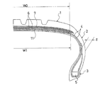
以下、本発明の構成について添付の図面を参照しながら詳細に説明する。図1は本発明の実施形態からなる空気入りタイヤを示すものである。図1において、1はトレッド部、2はサイドウォール部、3はビード部である。サイドウォール部2のタイヤ最大幅位置での総厚さTは5mm〜8mmに設定されている。サイドウォール部2の総厚さTが5mm未満であると優れた操縦安定性を発揮することが困難になり、逆に8mmを超えると乗り心地が悪化することになる。
Hereinafter, the configuration of the present invention will be described in detail with reference to the accompanying drawings. FIG. 1 shows a pneumatic tire according to an embodiment of the present invention. In FIG. 1, 1 is a tread portion, 2 is a sidewall portion, and 3 is a bead portion. The total thickness T of the
図1に示すように、一対のビード部3,3間には、引き揃えられた複数本のカーカスコードからなる複数層のカーカス層4が装架されている。カーカスコードとしては、レーヨン、ポリエステル、ナイロン、アラミド等の有機繊維コードを使用することが好ましいが、スチールコードを使用することも可能である。カーカス層4のタイヤ周方向に対するコード角度は、特に限定されるものではないが、65°〜86°の範囲に設定し、しかもカーカスコードを層間で互いに交差させることが好ましい。このような構成は操縦安定性の向上に寄与する。これらカーカス層4はビードコア5の廻りにタイヤ内側から外側へ巻き上げられている。
As shown in FIG. 1, a plurality of carcass layers 4 including a plurality of aligned carcass cords are mounted between a pair of
一方、トレッド部1におけるカーカス層4の外周側には複数層のベルト層6が配置されている。これらベルト層6はタイヤ周方向に対して傾斜する複数本の補強コードを含み、かつ補強コードが層間で互いに交差するように配置されている。ベルト層6のタイヤ周方向に対するコード角度は、10°〜40°の範囲、好ましくは20°〜30°の範囲に設定されている。そして、ベルト層6の外周側にはタイヤ周方向に対して実質的に0°の角度で配向する補強コードを含むベルトカバー層7が配置されている。
On the other hand, a plurality of
上記ベルト層6のうち少なくとも1層の補強コードとしては、高弾性率を有する有機繊維コードが使用されている。このようにトレッド部1におけるカーカス層4の外周側に有機繊維コードからなるベルト層6を配置することにより、空気入りタイヤの乗り心地を向上し、更には軽量化を図ることができる。高弾性率を有する有機繊維コードとしては、アラミド、ポリエチレンテレフタレート(PET)、ポリエチレンナフタレート(PEN)、ポリベンゾオキサゾール(PBO)、ポリオレフィンケトン(POK)等の有機繊維コードが有効である。乗り心地の向上と軽量化の観点から、全てのベルト層6を有機繊維コードから構成することが望ましいが、必要に応じてスチールコードからなるベルト層を組み合わせても良い。
As the reinforcing cord of at least one layer of the
上記空気入りタイヤにおいて、ベルト層6のタイヤ径方向内側位置においてカーカス層4の層間には補強ゴム層11が配置されている。このようにベルト層6のタイヤ径方向内側位置においてカーカス層4の層間に補強ゴム層11を配置することにより、トレッド部1の曲げ剛性を増大し、高負荷条件でのコーナリング時におけるトレッド面の浮き上がりを抑制することができる。そのため、上述のように有機繊維コードからなるベルト層6を採用した場合であっても、操縦安定性の低下を回避することができる。
In the pneumatic tire, a reinforcing
上記補強ゴム層11はカーカス層4の層間に介在させる必要がある。つまり、補強ゴム層11をベルト層6とカーカス層4との間に挿入した場合、ベルト層6とカーカス層4との間の層間剪断力に対する抗力が低下して操縦安定性が損なわれることになる。また、補強ゴム層11をカーカス層4よりもタイヤ径方向内側に配置した場合(例えば、カーカス層4とインナーライナー層との間に挿入した場合)、曲げ剛性の増大効果が不十分になる。なお、カーカス層4が例えば3層構造である場合、内側2層の層間位置と外側2層の層間位置との両方に補強ゴム層11を挿入することが可能であるが、2つの層間位置のいずれか一方だけに補強ゴム層11を挿入するようにしても良い。
The reinforcing
補強ゴム層11は一対のカーカス層4を離間させることで曲げ剛性を増大させるものであるため、その構成材料はカーカス層4のコートゴムと同一であっても良い。しかしながら、補強ゴム層11の構成材料をカーカス層4のコートゴムとは異ならせ、カーカス層4のコートゴムの100%モジュラスに対する補強ゴム層11の100%モジュラスの比を1.1〜3.5の範囲にすると良い。これにより、トレッド面の浮き上がりを効果的に抑制する一方で、補強ゴム層11のエッジ付近での剛性差を最小限に抑えることができる。上記モジュラス比が1.1未満であるとトレッド面の浮き上がりを抑制する効果が低下するため操縦安定性が低下し、逆に3.5を超えると補強ゴム層11のエッジ付近での剛性変化が大きくなるため乗り心地と耐久性が低下する。上記モジュラス比を得るには、ゴム成分や配合剤を適宜選択することで補強ゴム層11の100%モジュラスを大きくすれば良い。また、補強ゴム層11に短繊維を配合することも有効である。
Since the reinforcing
補強ゴム層11の幅W1はトレッド部1における最も狭いベルト層6の幅W0の60%〜110%の範囲にすると良い。これにより、トレッド面の浮き上がりを効果的に抑制する一方で、トレッド部1のフレックスゾーンの適度に確保することができる。補強ゴム層11の幅W1が最も狭いベルト層6の幅W0の60%未満であるとトレッド面の浮き上がりを抑制する効果が低下するため操縦安定性が低下し、逆に110%を超えるとトレッド部1のフレックスゾーンが減少するため乗り心地と耐久性が低下する。なお、補強ゴム層11は幅方向の中心位置がタイヤ赤道と一致するように左右対称に配置されることが好ましいが、製造誤差等による位置ずれは許容するものである。
The width W1 of the reinforcing
補強ゴム層11の平均厚さは0.5mm〜2.0mmの範囲にすると良い。これにより、トレッド面の浮き上がりを効果的に抑制する一方で、補強ゴム層11のエッジ付近での剛性差を最小限に抑えることができる。補強ゴム層11の平均厚さは0.5mm未満であるとトレッド面の浮き上がりを抑制する効果が低下するため操縦安定性が低下し、逆に2.0mmを超えると補強ゴム層11のエッジ付近での剛性変化が大きくなるため乗り心地と耐久性が低下する。
The average thickness of the reinforcing
本発明は、各種の空気入りタイヤに適用可能であるが、特にトレッドゴムの厚さが3.0mm〜5.0mmであるレース用タイヤに適用した場合に顕著な作用効果を得ることができる。即ち、トレッドゴムが薄いレース用タイヤでは、有機繊維コードからなるベルト層がトレッド部の剛性に与える影響が顕著であり、しかもコーナリング時の接地性が操縦安定性に大きな影響を与えるからである。 The present invention can be applied to various types of pneumatic tires. However, when the present invention is applied to a racing tire in which the thickness of the tread rubber is 3.0 mm to 5.0 mm, a remarkable effect can be obtained. That is, in a racing tire with a thin tread rubber, the belt layer made of an organic fiber cord has a significant effect on the rigidity of the tread portion, and the grounding property during cornering greatly affects the handling stability.
タイヤサイズ225/40R18で、一対のビード部間に2層のカーカス層を装架し、トレッド部におけるカーカス層の外周側に2層のベルト層を配置すると共に、タイヤ最大幅位置でのサイドウォール部の総厚さを12mmとした空気入りタイヤにおいて、ベルト層の材質、補強ゴム層の位置、カーカス層のコートゴムの20℃での100%モジュラスに対する補強ゴム層の20℃での100%モジュラスの比、補強ゴム層の平均厚さを表1及び表2のように設定した従来例、比較例1〜2及び実施例1〜12のタイヤをそれぞれ製作した。なお、トレッド部における最も狭いベルト層の幅は200mmである。 With tire size 225 / 40R18, two carcass layers are mounted between a pair of bead portions, two belt layers are arranged on the outer periphery side of the carcass layer in the tread portion, and the sidewall at the tire maximum width position In a pneumatic tire having a total thickness of 12 mm, the material of the belt layer, the position of the reinforcing rubber layer, the 100% modulus of the reinforcing rubber layer at 20 ° C. of the coated rubber of the carcass layer at 20 ° C. The tires of conventional examples, comparative examples 1 and 2 and examples 1 to 12 in which the ratio and the average thickness of the reinforcing rubber layer were set as shown in Tables 1 and 2 were produced. The width of the narrowest belt layer in the tread portion is 200 mm.
これら試験タイヤについて、下記試験方法により、操縦安定性、乗り心地、耐久性を評価し、その結果を表1及び表2に併せて示した。 These test tires were evaluated for steering stability, riding comfort, and durability by the following test methods, and the results are also shown in Tables 1 and 2.
操縦安定性:
試験タイヤをリムサイズ18×8JJのホイールに組み付けて試験車両に装着し、空気圧220kPaの条件で、操縦安定性についてテストドライバーによる官能評価を実施した。評価結果は、従来例を100とする指数にて示した。この指数値が大きいほど操縦安定性が優れていることを意味する。
Steering stability:
The test tire was assembled on a wheel with a rim size of 18 × 8 JJ and mounted on a test vehicle, and a sensory evaluation was performed by a test driver on steering stability under the condition of an air pressure of 220 kPa. The evaluation results are shown as an index with the conventional example being 100. The larger the index value, the better the steering stability.
乗り心地:
試験タイヤをリムサイズ18×8JJのホイールに組み付けて試験車両に装着し、空気圧220kPaの条件で、乗り心地についてテストドライバーによる官能評価を実施した。評価結果は、従来例を100とする指数にて示した。この指数値が大きいほど乗り心地が優れていることを意味する。
Ride comfort:
The test tire was assembled on a rim size 18 × 8 JJ wheel and mounted on a test vehicle, and a sensory evaluation was performed on the ride comfort by a test driver under the condition of an air pressure of 220 kPa. The evaluation results are shown as an index with the conventional example being 100. The larger the index value, the better the ride comfort.
耐久性:
試験タイヤをリムサイズ18×8JJのホイールに組み付けてドラム径1707mmのドラム試験機に装着し、空気圧240kPa、速度81km/hの条件で、最大負荷能力の88%から2時間毎に13%ずつ荷重を増加させて32時間走行した後、試験タイヤを切断し、補強ゴム層のエッジ付近に生じたカーカス層のセパレーション部分の大きさを測定した。評価結果は、測定値の逆数を用い、従来例を100とする指数にて示した。この指数値が大きいほど耐久性が優れていることを意味する。
durability:
The test tire is mounted on a wheel with a rim size of 18 x 8 JJ and mounted on a drum testing machine with a drum diameter of 1707 mm. Under the conditions of air pressure of 240 kPa and speed of 81 km / h, a load of 13% is applied every 88 hours from 88% of the maximum load capacity. After increasing and running for 32 hours, the test tire was cut, and the size of the separation portion of the carcass layer generated near the edge of the reinforcing rubber layer was measured. The evaluation results are shown as an index with the conventional example being 100, using the reciprocal of the measured value. The larger the index value, the better the durability.

表1及び表2に示すように、実施例1〜12のタイヤは、スチールコードからなるベルト層を備えた従来例との対比において、操縦安定性、乗り心地、耐久性がバランス良く改善されていた。特に、カーカス層のコートゴムの100%モジュラスに対する補強ゴム層の100%モジュラスの比が1.1〜3.5の範囲にある場合、補強ゴム層の幅がトレッド部における最も狭いベルト層の幅の60%〜110%の範囲にある場合、及び、補強ゴム層の平均厚さは0.5mm〜2.0mmの範囲にある場合に良好な結果が得られていた。 As shown in Tables 1 and 2, the tires of Examples 1 to 12 are improved in a balanced manner in terms of handling stability, riding comfort, and durability in comparison with the conventional examples including a belt layer made of a steel cord. It was. In particular, when the ratio of the 100% modulus of the reinforcing rubber layer to the 100% modulus of the coat rubber of the carcass layer is in the range of 1.1 to 3.5, the width of the reinforcing rubber layer is the width of the narrowest belt layer in the tread portion. Good results were obtained when it was in the range of 60% to 110% and when the average thickness of the reinforcing rubber layer was in the range of 0.5 mm to 2.0 mm.
一方、比較例1のタイヤは、補強ゴム層を備えていないため操縦安定性が低下していた。比較例2のタイヤは、補強ゴム層の位置がベルト層とカーカス層との間であるため操縦安定性が低下していた。 On the other hand, since the tire of Comparative Example 1 did not include the reinforcing rubber layer, the steering stability was lowered. The tire of Comparative Example 2 had poor steering stability because the position of the reinforcing rubber layer was between the belt layer and the carcass layer.
1 トレッド部
2 サイドウォール部
3 ビード部
4 カーカス層
5 ビードコア
6 ベルト層
7 ベルトカバー層
11 補強ゴム層
DESCRIPTION OF SYMBOLS 1
Claims (4)
Priority Applications (1)
| Application Number | Priority Date | Filing Date | Title |
|---|---|---|---|
| JP2008163689A JP5077094B2 (en) | 2008-06-23 | 2008-06-23 | Pneumatic tire |
Applications Claiming Priority (1)
| Application Number | Priority Date | Filing Date | Title |
|---|---|---|---|
| JP2008163689A JP5077094B2 (en) | 2008-06-23 | 2008-06-23 | Pneumatic tire |
Publications (2)
| Publication Number | Publication Date |
|---|---|
| JP2010000993A true JP2010000993A (en) | 2010-01-07 |
| JP5077094B2 JP5077094B2 (en) | 2012-11-21 |
Family
ID=41583066
Family Applications (1)
| Application Number | Title | Priority Date | Filing Date |
|---|---|---|---|
| JP2008163689A Expired - Fee Related JP5077094B2 (en) | 2008-06-23 | 2008-06-23 | Pneumatic tire |
Country Status (1)
| Country | Link |
|---|---|
| JP (1) | JP5077094B2 (en) |
Cited By (3)
| Publication number | Priority date | Publication date | Assignee | Title |
|---|---|---|---|---|
| JP2014162268A (en) * | 2013-02-22 | 2014-09-08 | Sumitomo Rubber Ind Ltd | Pneumatic tire |
| WO2017175675A1 (en) * | 2016-04-08 | 2017-10-12 | 横浜ゴム株式会社 | Pneumatic tire |
| WO2017195889A1 (en) * | 2016-05-12 | 2017-11-16 | 横浜ゴム株式会社 | Pneumatic tire |
Citations (4)
| Publication number | Priority date | Publication date | Assignee | Title |
|---|---|---|---|---|
| JPH05278413A (en) * | 1992-04-06 | 1993-10-26 | Yokohama Rubber Co Ltd:The | Pneumatic radial tire for passenger car |
| JP2001047810A (en) * | 1999-08-11 | 2001-02-20 | Yokohama Rubber Co Ltd:The | Pneumatic bias racing tire |
| JP2004067059A (en) * | 2002-08-09 | 2004-03-04 | Bridgestone Corp | Pneumatic tire for motorcycle |
| JP2006137283A (en) * | 2004-11-11 | 2006-06-01 | Sumitomo Rubber Ind Ltd | Pneumatic tire for racing cart |
-
2008
- 2008-06-23 JP JP2008163689A patent/JP5077094B2/en not_active Expired - Fee Related
Patent Citations (4)
| Publication number | Priority date | Publication date | Assignee | Title |
|---|---|---|---|---|
| JPH05278413A (en) * | 1992-04-06 | 1993-10-26 | Yokohama Rubber Co Ltd:The | Pneumatic radial tire for passenger car |
| JP2001047810A (en) * | 1999-08-11 | 2001-02-20 | Yokohama Rubber Co Ltd:The | Pneumatic bias racing tire |
| JP2004067059A (en) * | 2002-08-09 | 2004-03-04 | Bridgestone Corp | Pneumatic tire for motorcycle |
| JP2006137283A (en) * | 2004-11-11 | 2006-06-01 | Sumitomo Rubber Ind Ltd | Pneumatic tire for racing cart |
Cited By (12)
| Publication number | Priority date | Publication date | Assignee | Title |
|---|---|---|---|---|
| JP2014162268A (en) * | 2013-02-22 | 2014-09-08 | Sumitomo Rubber Ind Ltd | Pneumatic tire |
| WO2017175675A1 (en) * | 2016-04-08 | 2017-10-12 | 横浜ゴム株式会社 | Pneumatic tire |
| JPWO2017175675A1 (en) * | 2016-04-08 | 2018-08-30 | 横浜ゴム株式会社 | Pneumatic tire |
| CN108883664A (en) * | 2016-04-08 | 2018-11-23 | 横滨橡胶株式会社 | Pneumatic tire |
| EP3441239A4 (en) * | 2016-04-08 | 2020-02-12 | The Yokohama Rubber Co., Ltd. | Pneumatic tire |
| CN108883664B (en) * | 2016-04-08 | 2021-07-20 | 横滨橡胶株式会社 | Pneumatic tire |
| US11104180B2 (en) | 2016-04-08 | 2021-08-31 | The Yokohama Rubber Co., Ltd. | Pneumatic tire |
| WO2017195889A1 (en) * | 2016-05-12 | 2017-11-16 | 横浜ゴム株式会社 | Pneumatic tire |
| JP2017202754A (en) * | 2016-05-12 | 2017-11-16 | 横浜ゴム株式会社 | Pneumatic tire |
| CN109070639A (en) * | 2016-05-12 | 2018-12-21 | 横滨橡胶株式会社 | Pneumatic tire |
| US11135876B2 (en) | 2016-05-12 | 2021-10-05 | The Yokohama Rubber Co., Ltd. | Pneumatic tire |
| CN109070639B (en) * | 2016-05-12 | 2023-09-05 | 横滨橡胶株式会社 | pneumatic tire |
Also Published As
| Publication number | Publication date |
|---|---|
| JP5077094B2 (en) | 2012-11-21 |
Similar Documents
| Publication | Publication Date | Title |
|---|---|---|
| JP6241346B2 (en) | Pneumatic tire | |
| JP4744392B2 (en) | Pneumatic radial tire for motorcycles | |
| US20090294007A1 (en) | Performance tire with sidewall insert | |
| JP5239507B2 (en) | Pneumatic tire | |
| WO2015111439A1 (en) | Motorcycle tire | |
| JP2007125988A (en) | Pneumatic tire for motorcycle | |
| JP5294396B2 (en) | Pneumatic radial tire | |
| CN115362071A (en) | Pneumatic tire | |
| JP5077094B2 (en) | Pneumatic tire | |
| JP2013039851A (en) | Pneumatic tire | |
| CN114340912A (en) | Pneumatic tire | |
| JP5493590B2 (en) | Pneumatic radial tire | |
| JP2007030719A (en) | Pneumatic radial tire | |
| JP2001039113A (en) | Pneumatic tire | |
| JP2013035364A (en) | Pneumatic radial tire | |
| JP2002370507A (en) | Pneumatic radial tire | |
| JP5244462B2 (en) | Pneumatic tire | |
| JP4334945B2 (en) | Pneumatic tire | |
| CN113474184A (en) | Pneumatic tire | |
| JP2008223200A (en) | Reinforcing cord and pneumatic radial tire | |
| JP4842047B2 (en) | Pneumatic radial tire for motorcycles | |
| JP6523138B2 (en) | Pneumatic radial tire for motorcycles | |
| JP2004130859A (en) | Pneumatic radial tire | |
| JP2006192914A (en) | Pneumatic radial tire | |
| JP4963459B2 (en) | How to install a pneumatic tire |
Legal Events
| Date | Code | Title | Description |
|---|---|---|---|
| A621 | Written request for application examination |
Free format text: JAPANESE INTERMEDIATE CODE: A621 Effective date: 20090928 |
|
| A977 | Report on retrieval |
Free format text: JAPANESE INTERMEDIATE CODE: A971007 Effective date: 20111124 |
|
| A131 | Notification of reasons for refusal |
Free format text: JAPANESE INTERMEDIATE CODE: A131 Effective date: 20111213 |
|
| A521 | Written amendment |
Free format text: JAPANESE INTERMEDIATE CODE: A523 Effective date: 20120123 |
|
| TRDD | Decision of grant or rejection written | ||
| A01 | Written decision to grant a patent or to grant a registration (utility model) |
Free format text: JAPANESE INTERMEDIATE CODE: A01 Effective date: 20120731 |
|
| A01 | Written decision to grant a patent or to grant a registration (utility model) |
Free format text: JAPANESE INTERMEDIATE CODE: A01 |
|
| A61 | First payment of annual fees (during grant procedure) |
Free format text: JAPANESE INTERMEDIATE CODE: A61 Effective date: 20120813 |
|
| FPAY | Renewal fee payment (event date is renewal date of database) |
Free format text: PAYMENT UNTIL: 20150907 Year of fee payment: 3 |
|
| R150 | Certificate of patent or registration of utility model |
Free format text: JAPANESE INTERMEDIATE CODE: R150 |
|
| FPAY | Renewal fee payment (event date is renewal date of database) |
Free format text: PAYMENT UNTIL: 20150907 Year of fee payment: 3 |
|
| R250 | Receipt of annual fees |
Free format text: JAPANESE INTERMEDIATE CODE: R250 |
|
| R250 | Receipt of annual fees |
Free format text: JAPANESE INTERMEDIATE CODE: R250 |
|
| R250 | Receipt of annual fees |
Free format text: JAPANESE INTERMEDIATE CODE: R250 |
|
| LAPS | Cancellation because of no payment of annual fees |