JP2010000852A - Inverter arrangement structure of hybrid vehicle - Google Patents
Inverter arrangement structure of hybrid vehicle Download PDFInfo
- Publication number
- JP2010000852A JP2010000852A JP2008160317A JP2008160317A JP2010000852A JP 2010000852 A JP2010000852 A JP 2010000852A JP 2008160317 A JP2008160317 A JP 2008160317A JP 2008160317 A JP2008160317 A JP 2008160317A JP 2010000852 A JP2010000852 A JP 2010000852A
- Authority
- JP
- Japan
- Prior art keywords
- vehicle
- inverter
- engine
- width direction
- cross member
- Prior art date
- Legal status (The legal status is an assumption and is not a legal conclusion. Google has not performed a legal analysis and makes no representation as to the accuracy of the status listed.)
- Granted
Links
- 239000000725 suspension Substances 0.000 claims description 31
- 230000002787 reinforcement Effects 0.000 claims description 9
- 238000010276 construction Methods 0.000 claims 1
- 230000002093 peripheral effect Effects 0.000 description 7
- UFHFLCQGNIYNRP-UHFFFAOYSA-N Hydrogen Chemical compound [H][H] UFHFLCQGNIYNRP-UHFFFAOYSA-N 0.000 description 6
- 239000003502 gasoline Substances 0.000 description 6
- 239000001257 hydrogen Substances 0.000 description 6
- 229910052739 hydrogen Inorganic materials 0.000 description 6
- 239000002828 fuel tank Substances 0.000 description 4
- 238000003466 welding Methods 0.000 description 4
- 230000001133 acceleration Effects 0.000 description 3
- 230000004308 accommodation Effects 0.000 description 3
- 238000010586 diagram Methods 0.000 description 3
- 239000000446 fuel Substances 0.000 description 3
- 238000002347 injection Methods 0.000 description 3
- 239000007924 injection Substances 0.000 description 3
- NJPPVKZQTLUDBO-UHFFFAOYSA-N novaluron Chemical compound C1=C(Cl)C(OC(F)(F)C(OC(F)(F)F)F)=CC=C1NC(=O)NC(=O)C1=C(F)C=CC=C1F NJPPVKZQTLUDBO-UHFFFAOYSA-N 0.000 description 3
- 230000003014 reinforcing effect Effects 0.000 description 3
- 238000006243 chemical reaction Methods 0.000 description 2
- 230000009977 dual effect Effects 0.000 description 2
- 239000010687 lubricating oil Substances 0.000 description 2
- 230000001105 regulatory effect Effects 0.000 description 2
- 238000002485 combustion reaction Methods 0.000 description 1
- 230000006835 compression Effects 0.000 description 1
- 238000007906 compression Methods 0.000 description 1
- 230000006866 deterioration Effects 0.000 description 1
- 239000000428 dust Substances 0.000 description 1
- 230000000694 effects Effects 0.000 description 1
- 238000009434 installation Methods 0.000 description 1
- 238000002955 isolation Methods 0.000 description 1
- 238000012986 modification Methods 0.000 description 1
- 230000004048 modification Effects 0.000 description 1
- 238000005192 partition Methods 0.000 description 1
- 238000010248 power generation Methods 0.000 description 1
- 230000001172 regenerating effect Effects 0.000 description 1
- 238000005096 rolling process Methods 0.000 description 1
Images


Classifications
-
- B—PERFORMING OPERATIONS; TRANSPORTING
- B60—VEHICLES IN GENERAL
- B60L—PROPULSION OF ELECTRICALLY-PROPELLED VEHICLES; SUPPLYING ELECTRIC POWER FOR AUXILIARY EQUIPMENT OF ELECTRICALLY-PROPELLED VEHICLES; ELECTRODYNAMIC BRAKE SYSTEMS FOR VEHICLES IN GENERAL; MAGNETIC SUSPENSION OR LEVITATION FOR VEHICLES; MONITORING OPERATING VARIABLES OF ELECTRICALLY-PROPELLED VEHICLES; ELECTRIC SAFETY DEVICES FOR ELECTRICALLY-PROPELLED VEHICLES
- B60L7/00—Electrodynamic brake systems for vehicles in general
- B60L7/10—Dynamic electric regenerative braking
- B60L7/14—Dynamic electric regenerative braking for vehicles propelled by AC motors
-
- B—PERFORMING OPERATIONS; TRANSPORTING
- B60—VEHICLES IN GENERAL
- B60L—PROPULSION OF ELECTRICALLY-PROPELLED VEHICLES; SUPPLYING ELECTRIC POWER FOR AUXILIARY EQUIPMENT OF ELECTRICALLY-PROPELLED VEHICLES; ELECTRODYNAMIC BRAKE SYSTEMS FOR VEHICLES IN GENERAL; MAGNETIC SUSPENSION OR LEVITATION FOR VEHICLES; MONITORING OPERATING VARIABLES OF ELECTRICALLY-PROPELLED VEHICLES; ELECTRIC SAFETY DEVICES FOR ELECTRICALLY-PROPELLED VEHICLES
- B60L15/00—Methods, circuits, or devices for controlling the traction-motor speed of electrically-propelled vehicles
- B60L15/20—Methods, circuits, or devices for controlling the traction-motor speed of electrically-propelled vehicles for control of the vehicle or its driving motor to achieve a desired performance, e.g. speed, torque, programmed variation of speed
- B60L15/2009—Methods, circuits, or devices for controlling the traction-motor speed of electrically-propelled vehicles for control of the vehicle or its driving motor to achieve a desired performance, e.g. speed, torque, programmed variation of speed for braking
-
- B—PERFORMING OPERATIONS; TRANSPORTING
- B60—VEHICLES IN GENERAL
- B60L—PROPULSION OF ELECTRICALLY-PROPELLED VEHICLES; SUPPLYING ELECTRIC POWER FOR AUXILIARY EQUIPMENT OF ELECTRICALLY-PROPELLED VEHICLES; ELECTRODYNAMIC BRAKE SYSTEMS FOR VEHICLES IN GENERAL; MAGNETIC SUSPENSION OR LEVITATION FOR VEHICLES; MONITORING OPERATING VARIABLES OF ELECTRICALLY-PROPELLED VEHICLES; ELECTRIC SAFETY DEVICES FOR ELECTRICALLY-PROPELLED VEHICLES
- B60L50/00—Electric propulsion with power supplied within the vehicle
- B60L50/50—Electric propulsion with power supplied within the vehicle using propulsion power supplied by batteries or fuel cells
- B60L50/60—Electric propulsion with power supplied within the vehicle using propulsion power supplied by batteries or fuel cells using power supplied by batteries
- B60L50/61—Electric propulsion with power supplied within the vehicle using propulsion power supplied by batteries or fuel cells using power supplied by batteries by batteries charged by engine-driven generators, e.g. series hybrid electric vehicles
- B60L50/62—Electric propulsion with power supplied within the vehicle using propulsion power supplied by batteries or fuel cells using power supplied by batteries by batteries charged by engine-driven generators, e.g. series hybrid electric vehicles charged by low-power generators primarily intended to support the batteries, e.g. range extenders
-
- B—PERFORMING OPERATIONS; TRANSPORTING
- B60—VEHICLES IN GENERAL
- B60L—PROPULSION OF ELECTRICALLY-PROPELLED VEHICLES; SUPPLYING ELECTRIC POWER FOR AUXILIARY EQUIPMENT OF ELECTRICALLY-PROPELLED VEHICLES; ELECTRODYNAMIC BRAKE SYSTEMS FOR VEHICLES IN GENERAL; MAGNETIC SUSPENSION OR LEVITATION FOR VEHICLES; MONITORING OPERATING VARIABLES OF ELECTRICALLY-PROPELLED VEHICLES; ELECTRIC SAFETY DEVICES FOR ELECTRICALLY-PROPELLED VEHICLES
- B60L2210/00—Converter types
- B60L2210/30—AC to DC converters
-
- B—PERFORMING OPERATIONS; TRANSPORTING
- B60—VEHICLES IN GENERAL
- B60L—PROPULSION OF ELECTRICALLY-PROPELLED VEHICLES; SUPPLYING ELECTRIC POWER FOR AUXILIARY EQUIPMENT OF ELECTRICALLY-PROPELLED VEHICLES; ELECTRODYNAMIC BRAKE SYSTEMS FOR VEHICLES IN GENERAL; MAGNETIC SUSPENSION OR LEVITATION FOR VEHICLES; MONITORING OPERATING VARIABLES OF ELECTRICALLY-PROPELLED VEHICLES; ELECTRIC SAFETY DEVICES FOR ELECTRICALLY-PROPELLED VEHICLES
- B60L2210/00—Converter types
- B60L2210/40—DC to AC converters
-
- B—PERFORMING OPERATIONS; TRANSPORTING
- B60—VEHICLES IN GENERAL
- B60L—PROPULSION OF ELECTRICALLY-PROPELLED VEHICLES; SUPPLYING ELECTRIC POWER FOR AUXILIARY EQUIPMENT OF ELECTRICALLY-PROPELLED VEHICLES; ELECTRODYNAMIC BRAKE SYSTEMS FOR VEHICLES IN GENERAL; MAGNETIC SUSPENSION OR LEVITATION FOR VEHICLES; MONITORING OPERATING VARIABLES OF ELECTRICALLY-PROPELLED VEHICLES; ELECTRIC SAFETY DEVICES FOR ELECTRICALLY-PROPELLED VEHICLES
- B60L2240/00—Control parameters of input or output; Target parameters
- B60L2240/40—Drive Train control parameters
- B60L2240/42—Drive Train control parameters related to electric machines
- B60L2240/423—Torque
-
- B—PERFORMING OPERATIONS; TRANSPORTING
- B60—VEHICLES IN GENERAL
- B60L—PROPULSION OF ELECTRICALLY-PROPELLED VEHICLES; SUPPLYING ELECTRIC POWER FOR AUXILIARY EQUIPMENT OF ELECTRICALLY-PROPELLED VEHICLES; ELECTRODYNAMIC BRAKE SYSTEMS FOR VEHICLES IN GENERAL; MAGNETIC SUSPENSION OR LEVITATION FOR VEHICLES; MONITORING OPERATING VARIABLES OF ELECTRICALLY-PROPELLED VEHICLES; ELECTRIC SAFETY DEVICES FOR ELECTRICALLY-PROPELLED VEHICLES
- B60L2240/00—Control parameters of input or output; Target parameters
- B60L2240/40—Drive Train control parameters
- B60L2240/44—Drive Train control parameters related to combustion engines
- B60L2240/441—Speed
-
- Y—GENERAL TAGGING OF NEW TECHNOLOGICAL DEVELOPMENTS; GENERAL TAGGING OF CROSS-SECTIONAL TECHNOLOGIES SPANNING OVER SEVERAL SECTIONS OF THE IPC; TECHNICAL SUBJECTS COVERED BY FORMER USPC CROSS-REFERENCE ART COLLECTIONS [XRACs] AND DIGESTS
- Y02—TECHNOLOGIES OR APPLICATIONS FOR MITIGATION OR ADAPTATION AGAINST CLIMATE CHANGE
- Y02T—CLIMATE CHANGE MITIGATION TECHNOLOGIES RELATED TO TRANSPORTATION
- Y02T10/00—Road transport of goods or passengers
- Y02T10/60—Other road transportation technologies with climate change mitigation effect
- Y02T10/62—Hybrid vehicles
-
- Y—GENERAL TAGGING OF NEW TECHNOLOGICAL DEVELOPMENTS; GENERAL TAGGING OF CROSS-SECTIONAL TECHNOLOGIES SPANNING OVER SEVERAL SECTIONS OF THE IPC; TECHNICAL SUBJECTS COVERED BY FORMER USPC CROSS-REFERENCE ART COLLECTIONS [XRACs] AND DIGESTS
- Y02—TECHNOLOGIES OR APPLICATIONS FOR MITIGATION OR ADAPTATION AGAINST CLIMATE CHANGE
- Y02T—CLIMATE CHANGE MITIGATION TECHNOLOGIES RELATED TO TRANSPORTATION
- Y02T10/00—Road transport of goods or passengers
- Y02T10/60—Other road transportation technologies with climate change mitigation effect
- Y02T10/64—Electric machine technologies in electromobility
-
- Y—GENERAL TAGGING OF NEW TECHNOLOGICAL DEVELOPMENTS; GENERAL TAGGING OF CROSS-SECTIONAL TECHNOLOGIES SPANNING OVER SEVERAL SECTIONS OF THE IPC; TECHNICAL SUBJECTS COVERED BY FORMER USPC CROSS-REFERENCE ART COLLECTIONS [XRACs] AND DIGESTS
- Y02—TECHNOLOGIES OR APPLICATIONS FOR MITIGATION OR ADAPTATION AGAINST CLIMATE CHANGE
- Y02T—CLIMATE CHANGE MITIGATION TECHNOLOGIES RELATED TO TRANSPORTATION
- Y02T10/00—Road transport of goods or passengers
- Y02T10/60—Other road transportation technologies with climate change mitigation effect
- Y02T10/70—Energy storage systems for electromobility, e.g. batteries
-
- Y—GENERAL TAGGING OF NEW TECHNOLOGICAL DEVELOPMENTS; GENERAL TAGGING OF CROSS-SECTIONAL TECHNOLOGIES SPANNING OVER SEVERAL SECTIONS OF THE IPC; TECHNICAL SUBJECTS COVERED BY FORMER USPC CROSS-REFERENCE ART COLLECTIONS [XRACs] AND DIGESTS
- Y02—TECHNOLOGIES OR APPLICATIONS FOR MITIGATION OR ADAPTATION AGAINST CLIMATE CHANGE
- Y02T—CLIMATE CHANGE MITIGATION TECHNOLOGIES RELATED TO TRANSPORTATION
- Y02T10/00—Road transport of goods or passengers
- Y02T10/60—Other road transportation technologies with climate change mitigation effect
- Y02T10/72—Electric energy management in electromobility
Landscapes
- Engineering & Computer Science (AREA)
- Power Engineering (AREA)
- Transportation (AREA)
- Mechanical Engineering (AREA)
- Life Sciences & Earth Sciences (AREA)
- Sustainable Development (AREA)
- Sustainable Energy (AREA)
- Cooling, Air Intake And Gas Exhaust, And Fuel Tank Arrangements In Propulsion Units (AREA)
- Hybrid Electric Vehicles (AREA)
- Body Structure For Vehicles (AREA)
- Arrangement Or Mounting Of Propulsion Units For Vehicles (AREA)
Abstract
Description
本発明は、エンジン及びモータを車幅方向に並列配置した車両前部のエンジンルームにインバータを配設するハイブリッド車両のインバータ配設構造に関するものである。 The present invention relates to an inverter arrangement structure for a hybrid vehicle in which an inverter is arranged in an engine room in a front portion of a vehicle in which an engine and a motor are arranged in parallel in the vehicle width direction.
従来より、エンジンとモータとを備えたハイブリッド車両が知られている。このようなハイブリッド車両では、モータをインバータを介して高電圧バッテリに接続しており、バッテリからの電力をモータに供給する際には、バッテリから出力された直流電力は、インバータにより所定の周波数の交流電力に変換されてモータへと供給される。 Conventionally, a hybrid vehicle including an engine and a motor is known. In such a hybrid vehicle, the motor is connected to the high-voltage battery via the inverter, and when the electric power from the battery is supplied to the motor, the DC power output from the battery has a predetermined frequency by the inverter. It is converted into AC power and supplied to the motor.
ところで、ハイブリッド車両では、モータを車両前部に、エンジンを車両後部に配設することがあるが、そのように別々に配置すると、その取付の作業性が悪化する等の問題が生じる。 By the way, in a hybrid vehicle, the motor may be disposed at the front part of the vehicle and the engine may be disposed at the rear part of the vehicle. However, such separate arrangement causes problems such as deterioration of the mounting workability.
そこで、特許文献1に示すものでは、エンジン、モータ及びインバータを車両前部のエンジンルームに配設している。そして、インバータは、その前部が車体側に支持されている。
しかしながら、特許文献1のものでは、インバータは重量物であるにも拘わらず、その前部のみを車体側に支持しているだけなので、インバータを安定支持することができないという問題がある。この問題は、バッテリの充電を行う際にジェネレータで発生した交流電力を直流電力に変換する役割等も兼ねるインバータや、水冷式の冷却器を採用したインバータを備えたハイブリッド車両において顕著になる。
However, in the thing of
また、特許文献1のように、エンジンを車両前部のエンジンルームに配設すると、エンジン用のエアクリーナも同じくエンジンルームに配設することになるが、このエアクリーナも重量物であるので、これを安定支持したいという要求がある。
Further, as in
さらに、特許文献1のように、エンジンやモータ、重量物であるインバータ、エアクリーナを車両前部のエンジンルームに配設する場合、車両前部の車体剛性を向上させたいという要望もある。
Furthermore, as in
本発明は、かかる点に鑑みてなされたものであり、その目的とするところは、エンジン及びモータを車幅方向に並列配置した車両前部のエンジンルームにインバータを配設するハイブリッド車両のインバータ配設構造において、車両前部の車体剛性を向上させると共に、インバータ及びエンジン用のエアクリーナを安定支持することにある。 The present invention has been made in view of this point, and an object of the present invention is to provide an inverter arrangement for a hybrid vehicle in which an inverter is arranged in an engine room at the front of the vehicle in which an engine and a motor are arranged in parallel in the vehicle width direction. In the installation structure, the rigidity of the vehicle body at the front of the vehicle is improved and the inverter and the air cleaner for the engine are stably supported.
第1の発明は、エンジン及びモータを車幅方向に並列配置した車両前部のエンジンルームにインバータを配設するハイブリッド車両のインバータ配設構造であって、上記エンジンルームの車両前側及び後側には、車幅方向に延びて車体側部材に連結される前側及び後側クロスメンバがそれぞれ配設されており、上記インバータは、上記モータの上側で上記前側及び後側クロスメンバのそれぞれに支持されており、上記エンジン用のエアクリーナが、上記前側クロスメンバにおける上記インバータ支持部の車幅方向一方側に支持されていることを特徴とするものである。 1st invention is the inverter arrangement | positioning structure of the hybrid vehicle which arrange | positions an inverter in the engine room of the vehicle front part which arranged the engine and the motor in parallel in the vehicle width direction, Comprising: On the vehicle front side and rear side of the said engine room Are provided with front and rear cross members that extend in the vehicle width direction and are connected to the vehicle body side member, and the inverter is supported by the front and rear cross members above the motor. The air cleaner for the engine is supported on one side in the vehicle width direction of the inverter support portion in the front cross member.
これにより、エンジンルームの車両前側及び後側に、車幅方向に延びて車体側部材に連結される前側及び後側クロスメンバをそれぞれ配設しているので、車両前部の車体剛性を向上させることができる。 As a result, the front and rear cross members that extend in the vehicle width direction and are connected to the vehicle body side member are respectively provided on the vehicle front side and the rear side of the engine room, thereby improving the vehicle body rigidity of the vehicle front portion. be able to.
また、インバータをエンジンルームの車両前側及び後側にそれぞれ配設された前側及び後側クロスメンバのそれぞれに支持しているので、従来のように、インバータの前部のみを車体側に支持している場合と比較して、インバータを安定支持することができる。 In addition, since the inverter is supported on each of the front and rear cross members disposed on the front side and the rear side of the vehicle in the engine room, only the front part of the inverter is supported on the vehicle body side as in the prior art. Compared with the case where it is, the inverter can be supported stably.
さらに、重量物であるインバータを前側クロスメンバに支持しているので、前側クロスメンバの実質的なスパンを短くすることができ、前側クロスメンバのねじり剛性を向上させることができる。そして、そのような高ねじり剛性を持つ前側クロスメンバにおけるインバータ支持部の車幅方向一方側にエンジン用のエアクリーナを支持しているので、これを安定支持することができる。 Furthermore, since the heavy inverter is supported by the front cross member, the substantial span of the front cross member can be shortened, and the torsional rigidity of the front cross member can be improved. Since the engine air cleaner is supported on one side in the vehicle width direction of the inverter support portion of the front cross member having such high torsional rigidity, it can be stably supported.
第2の発明は、上記第1の発明において、上記前側クロスメンバは、上記エンジンルームの車幅方向両側に車両前後方向に延びるようにそれぞれ配設された上記車体側部材としての左右のフロントサイドフレームの間に架設連結されており、上記後側クロスメンバは、上記エンジンルームの車幅方向両側にそれぞれ配設された上記車体側部材としての左右のサスペンションタワーの間に架設連結されていることを特徴とするものである。 According to a second invention, in the first invention, the front cross member is a left and right front side as the vehicle body side member disposed so as to extend in the vehicle front-rear direction on both sides in the vehicle width direction of the engine room. The rear cross member is erected between the frames, and the rear cross member is erected between the left and right suspension towers as the vehicle body side members respectively disposed on both sides of the engine room in the vehicle width direction. It is characterized by.
これにより、前側クロスメンバを、エンジンルームの車幅方向両側に車両前後方向に延びるようにそれぞれ配設された比較的強度のある左右のフロントサイドフレームの間に架設連結すると共に、後側クロスメンバを、エンジンルームの車幅方向両側にそれぞれ配設された比較的強度のある左右のサスペンションタワーの間に架設連結しているので、前側クロスメンバの、インバータ及びエアクリーナの支持剛性を向上させることができると共に、後側クロスメンバのインバータ支持剛性を向上させることができる。よって、インバータ及びエアクリーナをより一層安定支持することができる。 As a result, the front cross member is constructed and connected between the relatively strong left and right front side frames respectively arranged to extend in the vehicle front-rear direction on both sides in the vehicle width direction of the engine room, and the rear cross member. Is installed between the relatively strong left and right suspension towers arranged on both sides in the vehicle width direction of the engine room, so that the support rigidity of the inverter and air cleaner of the front cross member can be improved. In addition, the inverter support rigidity of the rear cross member can be improved. Therefore, the inverter and the air cleaner can be supported more stably.
第3の発明は、上記第2の発明において、上記前側クロスメンバは、上記左右のフロントサイドフレームの前端にバンパーレインフォースメントと共に締結具で共締めされていることを特徴とするものである。 According to a third aspect, in the second aspect, the front cross member is fastened together with a bumper reinforcement to a front end of the left and right front side frames together with a fastener.
これにより、前側クロスメンバを、左右のフロントサイドフレームの前端にバンパーレインフォースメントと共に締結具で共締めしているので、前側クロスメンバ及びバンパーレインフォースメントを別々に左右のフロントサイドフレームに取り付ける場合と比較して、その取付作業を簡略化することができる。 As a result, the front cross member and the bumper reinforcement are fastened together with the fasteners at the front ends of the left and right front side frames, so the front cross member and the bumper reinforcement are attached to the left and right front side frames separately. Compared with, the mounting work can be simplified.
第4の発明は、上記第1〜3のいずれか1つの発明において、上記前側クロスメンバには、上記エアクリーナ支持用の支持部材が設けられており、上記支持部材は、上記前側クロスメンバに取り付けられたブラケットと、該ブラケットに支持され、上記エアクリーナを複数のマウントを介して載置支持するプレートとを有していることを特徴とするものである。 According to a fourth invention, in any one of the first to third inventions, the front cross member is provided with a support member for supporting the air cleaner, and the support member is attached to the front cross member. And a plate which is supported by the bracket and mounts and supports the air cleaner via a plurality of mounts.
これにより、エアクリーナを、前側クロスメンバにブラケットを介して支持された比較的広がりのあるプレートに載置支持しているので、前側クロスメンバに直接支持する場合と比較して、エアクリーナをより一層安定支持することができる。 As a result, the air cleaner is placed and supported on a relatively wide plate supported by the front cross member via the bracket, so that the air cleaner is more stable than when directly supported by the front cross member. Can be supported.
本発明によれば、エンジンルームの車両前側及び後側に、車幅方向に延びて車体側部材に連結される前側及び後側クロスメンバをそれぞれ配設しているので、車両前部の車体剛性を向上させることができる。 According to the present invention, the front and rear cross members that extend in the vehicle width direction and are connected to the vehicle body side member are disposed on the vehicle front side and the rear side of the engine room, respectively. Can be improved.
また、インバータをエンジンルームの車両前側及び後側にそれぞれ配設された前側及び後側クロスメンバのそれぞれに支持しているので、従来のように、インバータの前部のみを車体側に支持している場合と比較して、インバータを安定支持することができる。 In addition, since the inverter is supported on each of the front and rear cross members disposed on the front side and the rear side of the vehicle in the engine room, only the front part of the inverter is supported on the vehicle body side as in the prior art. Compared with the case where it is, the inverter can be supported stably.
さらに、重量物であるインバータを前側クロスメンバに支持しているので、前側クロスメンバの実質的なスパンを短くすることができ、前側クロスメンバのねじり剛性を向上させることができる。そして、そのような高ねじり剛性を持つ前側クロスメンバにおけるインバータ支持部の車幅方向一方側にエンジン用のエアクリーナを支持しているので、これを安定支持することができる。 Furthermore, since the heavy inverter is supported by the front cross member, the substantial span of the front cross member can be shortened, and the torsional rigidity of the front cross member can be improved. Since the engine air cleaner is supported on one side in the vehicle width direction of the inverter support portion of the front cross member having such high torsional rigidity, it can be stably supported.
以下、本発明の実施形態を図面に基づいて詳細に説明する。 Hereinafter, embodiments of the present invention will be described in detail with reference to the drawings.
−ハイブリッド車両の構成−
以下、本発明の実施形態に係るハイブリッド車両の構成について説明する。
-Configuration of hybrid vehicle-
Hereinafter, the configuration of the hybrid vehicle according to the embodiment of the present invention will be described.
図1は、本発明の実施形態に係るデュアルフューエルエンジン11(以下、エンジン11と呼ぶ)を搭載したハイブリッド車両1の概略構成図である。この車両1は、エンジン11及びモータ17を動力源として備え、このエンジン11は発電にのみ使用して、車両1が動くための動力は全てモータ17に頼る所謂シリーズハイブリッド車両である。車両1は、上記エンジン11及びモータ17の他に、高電圧バッテリ12(以下、バッテリ12と呼ぶ)と、上記エンジン11により駆動されるジェネレータ(発電機)13とを備えている。
FIG. 1 is a schematic configuration diagram of a
上記エンジン11は、使用燃料として、ガソリンと水素とを切換え可能に構成されている。また、エンジン11は、図示は省略するが、トロコイド内周面を有する繭状のロータハウジングとサイドハウジングとにより囲まれてなるロータ収容室(以下、気筒と呼ぶ)に概略三角形状のロータが収容されて構成されており、そのロータの外周側に3つの作動室が区画されている所謂ロータリーエンジンである。
The
上記ロータは、該ロータ外周の3つの頂部にそれぞれ配設されたシール部が各々ロータハウジングのトロコイド内周面に当接した状態でエキセントリックシャフト(駆動軸)11aの周りを自転しながら、該エキセントリックシャフト11aの軸心の周りに公転するようになっている。そして、ロータが1回転する間に、該ロータの各頂部間にそれぞれ形成された作動室が周方向に移動しながら、吸気、圧縮、膨張(燃焼)及び排気の各行程を行い、これにより発生する回転力がロータを介してエキセントリックシャフト11aから出力される。 The rotor rotates while rotating around the eccentric shaft (drive shaft) 11a in a state where seal portions respectively disposed at three tops of the outer periphery of the rotor are in contact with the inner peripheral surface of the trochoid of the rotor housing. It revolves around the shaft center of the shaft 11a. Then, while the rotor makes one revolution, the working chambers formed between the tops of the rotor move in the circumferential direction, and the intake, compression, expansion (combustion), and exhaust strokes are performed. The rotating force is output from the eccentric shaft 11a via the rotor.
上記エンジン11の気筒には、2つの点火プラグ(図示略)が設けられており、これらの点火プラグは、詳細は後述するプレート32qと対向配置されている。一方、気筒には、水素燃料タンク16から供給された水素を筒内に直接噴射する水素噴射用のインジェクタ(図示略)がそれぞれ設けられている。
The cylinder of the
また、上記気筒には、吸気行程にある作動室に連通するように吸気通路(図示略)が連通していると共に、排気行程にある作動室に連通するように排気通路(図示略)が連通している。吸気通路には、吸入空気中の異物やホコリを除去するためにフィルタを用いたエアクリーナ21が配設されている。
The cylinder is connected to an intake passage (not shown) so as to communicate with a working chamber in an intake stroke, and an exhaust passage (not shown) is connected to a working chamber in an exhaust stroke. is doing. An
吸気通路には、ガソリン燃料タンク15から供給されるガソリンを吸気通路内に噴射するためのガソリン噴射用のインジェクタ(図示略)が配設されている。 A gasoline injection injector (not shown) for injecting gasoline supplied from the gasoline fuel tank 15 into the intake passage is disposed in the intake passage.
そして、上記各点火プラグ、並びに水素及びガソリン噴射用の各インジェクタは、パワートレインコントロールモジュール(図示略。以下、PCMと呼ぶ)によって作動制御されるようになっている。 The ignition plugs and the injectors for hydrogen and gasoline injection are controlled by a powertrain control module (not shown; hereinafter referred to as PCM).
一方、上記バッテリ12は、ジェネレータ13及びモータ17にそれぞれ、インバータ20を介して接続されていて、ジェネレータ13からの発電電力及びモータ17からの回生電力が供給されることで充電される。また、該バッテリ12は、ジェネレータ13及びモータ17を駆動させるためのものであって、電力をジェネレータ13及びモータ17へ供給する。
On the other hand, the
上記ジェネレータ13は、その回転軸13a(図9のみ図示)が上記エンジン11の駆動軸11aと同軸上に配置されていて、該エンジン11によって直結駆動されており、この結果、ジェネレータ13は、エンジン11の回転数と同じ回転数で回転するようになっている。
The
上記モータ17は、両前輪(両駆動輪)18に前輪18用のディファレンシャルギア19(以下、デフ19と呼ぶ)を介して連結されていて、車両1の定速運転時等のように該モータ17に要求される出力トルク(以下、要求トルクと呼ぶ)が低い低トルク運転時や車両始動時にはバッテリ12から供給される電力により駆動され、中トルク運転時にはエンジン11により駆動されるジェネレータ13から供給される電力によって駆動され、急加速時等の要求トルクが高い高トルク運転時には該ジェネレータ13及びバッテリ12の双方から供給される電力により駆動される。このように、モータ17は、ジェネレータ13及びバッテリ12の両方からの電力により駆動されることがあるので、その外径はジェネレータ13の外径とほぼ同じであるものの、その最大出力はジェネレータ13の最大出力よりも大きくなっている(例えばジェネレータ13の最大出力が80kW、モータ17の最大出力が120kW)。
The
尚、バッテリ12の蓄電量が少ないときには、上記エンジン11を運転させてジェネレータ13を作動させることによって、モータ17を上記要求トルクで駆動するために必要な電力よりも大きな電力を該ジェネレータ13にて発生させると共に、該ジェネレータ13で発生した電力と上記モータ17の必要電力との差分をバッテリ12に供給して充電を行う。
When the amount of power stored in the
上記インバータ20は、AC−DCコンバータ20a及びDC−ACコンバータ20bとが一体化してなり、水冷式の冷却器(図示略)を採用しており、上記PCMにより制御されていて、バッテリ12、ジェネレータ13,及びモータ17の相互間での電力の授受及び変換を制御するように構成されている。
The
具体的には、上記AC−DCコンバータ20aは、交流電力を直流電力に変換し、上記DC−ACコンバータ20bは、直流電力を周波数等を制御した交流電力に変換するように構成されている。そして、ジェネレータ13からの電力をモータ17に供給する際には、該ジェネレータ13で発生した交流電力は一旦、AC−DCコンバータ20aにより直流電力に変換された後、再度、上記DC−ACコンバータ20bにより直流電力から交流電力に変換されてモータ17へと供給される。また、バッテリ12からの電力をモータ17に供給する際には、該バッテリ12から出力された直流電力は、上記DC−ACコンバータ20bにより所定の周波数の交流電力に変換されてモータ17へと供給される。またさらに、バッテリ12の充電を行う際には、ジェネレータ13で発生した交流電力はAC−DCコンバータ20aにより直流電力に変換されてバッテリ12へと供給される。
Specifically, the AC-
尚、バッテリ12、ガソリン燃料タンク15、及び水素燃料タンク16は、車両1後部(例えば後部座席近傍)に配置されている。
The
−ハイブリッド車両の前部車体構造−
以下、ハイブリッド車両1の前部車体構造について説明する。
-Front body structure of hybrid vehicle-
Hereinafter, the front vehicle body structure of the
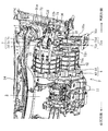
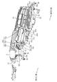
図2は、車両1前部のエンジンルーム3を上側から見た斜視図であり、図3は、インバータ20やエアクリーナ21を取り外した状態のエンジンルーム3を上側から見た斜視図であり、図4は、エンジンルーム3を下側から見た斜視図であり、図5は、エアクリーナ21やパワーユニットPを取り外した状態のエンジンルーム3を車両右側から見た斜視図であり、図6は、左側サスペンションタワー31a及び左側ホイールエプロン35をその裏面側から見た斜視図である。
2 is a perspective view of the
図2等中、符号30a,30bはエンジンルーム3の車幅方向両側に車両前後方向に延びるようにそれぞれ配設された左右のフロントサイドフレーム(車体側部材)であり、これらのフロントサイドフレーム30a,30bの高さ位置は、ジェネレータ13の上端(又はモータ17の下端)の高さ位置とほぼ同じである。31a,31bはエンジンルーム3車両後側の車幅方向両側にそれぞれ配設された左右のサスペンションタワー(車体側部材)であり、これらのサスペンションタワー31a,31bは、それぞれフロントサイドフレーム30a,30bの車幅方向外側に互いに車幅方向に対向配置されており、上端面の高さ位置がインバータ20上面の高さ位置とほぼ同じである。
In FIG. 2 and the like,
符号32は、詳細は後述するが、車両1前部の車体剛性を向上させるため、左右のフロントサイドフレーム30a,30b前端の上側部分の間に車幅方向に延びるように架設連結されたパイプ製の前側クロスメンバであり、この前側クロスメンバ32はエンジンルーム3の車両前側に配置されている。33は、同じく車両1前部の車体剛性を向上させるため、左右のサスペンションタワー31a,31b上端の間に車幅方向に延びるように架設連結されたパイプ製のサスペンションタワーバー(後側クロスメンバ)であり、このサスペンションタワーバー33は車両後側に配置されていて、その高さ位置が前側クロスメンバ32の高さ位置よりも上側に位置している(図17も参照)。サスペンションタワーバー33の中間部分(例えば右側部分)は、サスペンションタワーバー33よりも車両後方にある車体側部材34(本実施形態ではエンジンルーム3の車両後側に車幅方向に延びるように配設されたカウルボックス34)に連結支持されている。
符号35はエンジンルーム3の車両左側に車両前後方向に延びるように配設されたエンジンルーム3側壁としての左側ホイールエプロンであり、この左側ホイールエプロン35は、左側フロントサイドフレーム30aの車幅方向外側でかつ左側サスペンションタワー31aの車両前側に配置されている。また、左側ホイールエプロン35の裏面には、詳細は後述する左側防振マウント7の支持剛性を向上させるため、左側サスペンションタワー31aの裏面に跨って補強部材35aが設けられている。尚、詳細な説明は省略するが、エンジンルーム3の車両右側には、左側ホイールエプロン35と同様の右側ホイールエプロンが配設されている。
符号36は左側サスペンションタワー31aと左側ホイールエプロン35とに跨って車両前後方向に延びるように設けられたブラケットである。つまり、このブラケット36は左側フロントサイドフレーム30aの車幅方向外側に配置されている。ブラケット36は、その前部及び後部が左側サスペンションタワー31a及び左側ホイールエプロン35にそれぞれボルト固定されている。
符号37は左右のフロントサイドフレーム30a,30b前端の間に車幅方向に延びるように架設連結されたバンパーレインフォースメントであり、このバンパーレインフォースメント37は、左右のフロントサイドフレーム30a,30b前端に、エンジンルーム3の車幅方向両側に車両前後方向に延びるようにそれぞれ配設された左右のクラッシュカン37a,37bを介して、前側クロスメンバ32と共にボルト(締結具)38で共締めされている。具体的には、左右のフロントサイドフレーム30a,30b前端のフランジ30c,30d前面には、それぞれ左右のクラッシュカン37a,37b後端のフランジ37c,37d及び前側クロスメンバ32両端にそれぞれ溶接固定されたブラケット32a,32bがこの順に重ねられ、左右のフランジ37c,37d及びブラケット32a,32bが、それぞれ左右のフロントサイドフレーム30a,30bのフランジ30c,30dに共締め固定されている。39は左側フロントサイドフレーム30a前端と前側クロスメンバ32中間部分との間に架設連結されたパイプ製の補強メンバである。
−バイブリッド車両のパワーユニット搭載構造−
以下、ハイブリッド車両1のパワーユニット搭載構造について説明する。まず、パワーユニットPの構成について説明する。
-Power unit mounting structure for hybrid vehicles-
Hereinafter, the power unit mounting structure of the
図7は、パワーユニットPの斜視図であり、図8は、パワーユニットPの正面図であり、図9は、エンジン11を取り外した状態のパワーユニットPの斜視図であり、図10は、エンジン11やエンジン側ケーシング40を取り外した状態のパワーユニットPの側面図であり、図11は、図10のXI−XI線断面図である。
7 is a perspective view of the power unit P, FIG. 8 is a front view of the power unit P, FIG. 9 is a perspective view of the power unit P with the
図7等中、符号Pはエンジン11の後側(図8では右側)にジェネレータ13を、このジェネレータ13の上側にモータ17を配置してなるパワーユニット(パワープラント)である。このパワーユニットPは、その長手方向、すなわちエンジン11の駆動軸11aやジェネレータ13の回転軸13a、モータ17の回転軸(出力軸)17aが延びる方向が車幅方向(車両左右方向)となるように、エンジンルーム3に横置きに搭載されている。つまり、このエンジンルーム3には、エンジン11及びモータ17が車幅方向に並列配置されている。具体的には、モータ17は、サスペンションタワーバー33の下側で、その下部が車両正面視でジェネレータ13の上部と重なるように、車両側方視でジェネレータ13の上側かつ車両後側に配置されている。
In FIG. 7 and the like, symbol P denotes a power unit (power plant) in which a
パワーユニットPは、ジェネレータ13やモータ17、デフ19、詳細は後述する減速機構5を収容するユニットケーシング4を備えている。このユニットケーシング4は、エンジン11側(車両右側)にあるエンジン側ケーシング40と、エンジン11とは反対側(車両左側)にある反エンジン側ケーシング41とで形成されており、これらのケーシング40,41がボルト42,42,…で締結結合されている。つまり、ユニットケーシング4は、エンジン側ケーシング40と反エンジン側ケーシング41とが割り面で車幅方向に分割可能になっている。
The power unit P includes a
エンジン側ケーシング40の右端面(車幅方向内側端面)には、ジェネレータ13と対応する部分に開口40aが形成されており、この開口40aの周縁部にエンジン11がボルト結合されている。このように、エンジン11はエンジン側ケーシング40と、ひいてはユニットケーシング4と構造的に一体化されている。また、エンジン側ケーシング40のエンジン11側におけるモータ17と対応する部分は、蓋部40bで開閉可能となっている。
An
一方、反エンジン側ケーシング41は、モータ17回転軸17aの先端側が車両右側(車幅方向内側)になるように、ジェネレータ13及びモータ17を収容している。具体的には、反エンジン側ケーシング41には、車幅方向に延びる円状のジェネレータ用収容室41a(図17のみ図示)及びモータ用収容室41b(図11、図17のみ図示)がそれぞれ形成されており、これらの収容室41a,41bに、その車両左側(車幅方向外側)の開口からジェネレータ13及びモータ17がそれぞれ挿入装着されている。尚、当然のことながら、上述のように、モータ17をジェネレータ13の斜め上側後方に配置しているので、モータ用収容室41bもジェネレータ用収容室41aの斜め上側後方に位置している。また、反エンジン側ケーシング41は、ジェネレータ13及びモータ17本体部17bの略全体を収容するように、ジェネレータ13及びモータ17の左端面(車幅方向外側端面)近傍まで延設されており、この結果、反エンジン側ケーシング41の左端は、車両平面視で左側フロントサイドフレーム30aの車幅方向内側近傍に位置している。
On the other hand, the
以上のように、機械的結合のないジェネレータ13及びモータ17は単一物である反エンジン側ケーシング41に収容されており、この結果、ジェネレータ13及びモータ17は構造的に一体化し、エンジン11を含むパワーユニットPは、詳細は後述するが、その全体が構造的に一体のものとして車体側に支持されることになる。
As described above, the
次に、図10、図11を参照しながら、ユニットケーシング4の内部構造について説明する。
Next, the internal structure of the
上記モータ17の回転軸17aは、その出力が伝達される駆動モータ軸50に回転一体にスプライン結合されており、この駆動モータ軸50は、反エンジン側ケーシング41側の第1ボールベアリング51とエンジン側ケーシング40側の第2ボールベアリング52とによって支持されている。駆動モータ軸50の第1及び第2ボールベアリング51,52の間には第1駆動ギア53が一体に形成されている。駆動モータ軸50の第2ボールベアリング52よりもエンジン11側、すなわち第1駆動ギア53のモータ17とは反対側には、パーキングギア54が回転一体にスプライン結合されている。駆動モータ軸50は、その軸方向に中空に成形されていて、潤滑油が流出しないように先端がキャップ50aで密閉されると共に、ナット50bが締結されることによってパーキングギア54が抜け止めされている。
The
駆動モータ軸50の斜め下側後方には、第1中間軸55が設けられており、この第1中間軸55は、反エンジン側ケーシング41側の第1テーパベアリング56とエンジン側ケーシング40側の第2テーパベアリング57とによって支持されている。第1中間軸55のエンジン11とは反対側(車両左側)には、第1被動ギア58が一体に形成されており、この第1被動ギア58は、第1駆動ギア53と噛合して駆動されるようになっている。第1中間軸55のエンジン11側には、第2駆動ギア59が回転一体にスプライン結合されている。
A first
第1中間軸55の下側には、第2中間軸60が設けられており、この第2中間軸60は、反エンジン側ケーシング41側の第3テーパベアリング61とエンジン側ケーシング40側の第4テーパベアリング62とによって支持されている。第2中間軸60のエンジン11側には、第2被動ギア63が一体に形成されており、この第2被動ギア63は、第2駆動ギア59と噛合して駆動されるようになっている。第2中間軸60のエンジン11とは反対側には、第3駆動ギア64が回転一体にスプライン結合されている。
A second
上記デフ19は、車両側方視でジェネレータ13の車両後側でかつモータ17の下側に配置されている。デフ19は、詳細は図示しないが、サイドギアやピニオンギア等を覆うデフケース19aを備えており、このデフケース19aは、反エンジン側ケーシング41側の第5テーパベアリング65とエンジン側ケーシング40側の第6テーパベアリング66とによって支持されている。デフケース19aのエンジン11側には、デフリングギア19bがボルト結合されており、このデフリングギア19bは、第3駆動ギア64と噛合して駆動されるようになっている。そして、デフケース19aには、そのエンジン11側に右前輪駆動軸67が、エンジン11とは反対側に左前輪駆動軸68が連結されている。
The differential 19 is disposed on the vehicle rear side of the
以上のように、駆動モータ軸50とデフケース19aとの間には、第1及び第2中間軸55,60を介して、第1減速ギア対としての第1駆動ギア53及び第1被動ギア58、第2減速ギア対としての第2駆動ギア59及び第2被動ギア63、並びに第3減速ギア対としての第3駆動ギア64及びデフリングギア19bの3段よりなる減速ギア対が設けられており、これらの中間軸55,60や減速ギア対などが、モータ17からの回転を減速してデフ19に伝達する減速機構5を構成している。そして、この減速機構5は、上述したように、その一部がジェネレータ13及びモータ17と共に反エンジン側ケーシング41に、残りがエンジン側ケーシング40に収容されている。尚、詳細な説明は省略するが、図10、図11中の矢印は潤滑油の流れを示している。
As described above, the
次に、パワーユニットPのマウント構造について説明する。 Next, the mounting structure of the power unit P will be described.
図12は、パワーユニットPを車両後側から見た斜視図であり、図13は、パワーユニットPを上側から見た斜視図であり、図14は、防振マウント7の斜視図である。
12 is a perspective view of the power unit P viewed from the rear side of the vehicle, FIG. 13 is a perspective view of the power unit P viewed from the upper side, and FIG. 14 is a perspective view of the
図2〜4、図12〜14に示すように、パワーユニットPは、その車両左側(ジェネレータ13及びモータ17側)、車両右側(エンジン11側)、及び下側が車体側に3点支持されている。具体的には、パワーユニットPは、その長手方向両端部にそれぞれ配設された防振マウント7,8を介して左右のフロントサイドフレーム30a,30bに弾性支持されている。本実施形態のパワーユニットPでは、車両左側の方が右側よりも背が高いこと等から、長手方向に延びるロール慣性主軸(図示略)が車両左側から右側に向かって下向きに傾斜しており、これらの防振マウント7,8は、パワーユニットPのロール慣性主軸の真上近傍に配置されている。一方、パワーユニットPの下端部は、防振マウント9によってパワーユニットPよりも車両後方にある車体側部材90(本実施形態では車幅方向に延びるサスペンション支持用のサスペンションクロスメンバ90)に連結されている。そして、車両1の急加速時や急減速時におけるパワーユニットPのローリングや全体的な揺れは、主に、パワーユニットPの下端部に配設された防振マウント9によって規制されるが、左右の防振マウント装置7,8によっても規制される。すなわち、本実施形態では、パワーユニットPが加速時の駆動反力等によってローリングして、大きな車両前後方向の荷重が防振マウント装置7,8に入力されても、この荷重を左右の防振マウント装置7,8により受け止めて、パワーユニットPの揺れをより確実に規制できるようになっている。
As shown in FIGS. 2 to 4 and FIGS. 12 to 14, the power unit P is supported on the vehicle left side (
上記防振マウント7は、中空円筒状の内筒体7aと、この内筒体7aの周囲にこれと同軸に配設された中空円筒状の外筒体7bと、これらの両筒体7a,7bの間に配設されてこれらを互いに連結するゴム弾性体7cとを備えており、その筒軸方向が車両前後方向となるように配置されている。図13等中、符号7dは内筒体7aと外筒体7bとの車両前後方向の相対移動を規制するためのストッパーゴム弾性体である。
The
上記反エンジン側ケーシング41上部の左端部、すなわち上記モータ用収容室41b周縁部の上側部分の車幅方向外側端部には、防振マウント7支持用の二股状のパワーユニット側マウント支持ブラケット70が該反エンジン側ケーシング41から車両左側に延びるようにボルト固定されており、このパワーユニット側マウント支持ブラケット70は、その二股部70aが防振マウント7の内筒体7aにその中空部に挿通されたボルト71で締結固定されることによって、防振マウント7を支持している。
A bifurcated power unit side
上記左側フロントサイドフレーム30a及びブラケット36には、防振マウント7支持用の車体側マウント支持部材72が設けられている。具体的には、車体側マウント支持部材72は、左側フロントサイドフレーム30a上面に車両前後方向に延びるようにボルト固定された第1マウント支持ブラケット72aと、ブラケット36にボルト固定された概略コ字状の第2マウント支持ブラケット72bとを備えている。第1マウント支持ブラケット72aは、概略コ字状の上側部材72cと概略コ字状の下側部材72dとを上下に積み重ねてボルト結合してなり、上側部材72cにおける上細の両側壁部72e,72e上端に防振マウント7の外筒体7b外周面の下側部分が溶接固定されることによって、防振マウント7をその下側から支持している。一方、第2マウント支持ブラケット72bは、上細の両側壁部72f,72fを備えており、この両側壁部72f,72fの右端縁(車幅方向内側端縁)に外筒体7b外周面の車幅方向外側部分(左側部分)が溶接固定されることによって、防振マウント7をその車幅方向外側から支持している。以上のように、防振マウント7は、その下側及び車幅方向外側が車体側に2点支持されている。
The left
尚、右側及び下側の防振マウント8,9の詳細な説明は省略するが、その基本的な構造は従来周知のものである。 Although the detailed description of the right and lower anti-vibration mounts 8 and 9 is omitted, the basic structure is well known in the art.
−ハイブリッド車両のインバータ配設構造−
以下、ハイブリッド車両1のインバータ配設構造について説明する。
-Inverter arrangement structure for hybrid vehicles-
Hereinafter, the inverter arrangement structure of the
図15は、インバータ20及びエアクリーナ21を上側から見た斜視図であり、図16は、インバータ20及びエアクリーナ21を下側から見た斜視図であり、図17は、ジェネレータ13、モータ17及びインバータ21の配置関係を示す概略断面図である。尚、図17では、図を見易くするため、図を一部簡略化している。
15 is a perspective view of the
図2、図4、図5、図15〜17に示すように、インバータ20は、モータ17の上側で前側クロスメンバ32及びサスペンションタワーバー33のそれぞれに連結支持されている。具体的には、インバータ20の前部は、前側クロスメンバ32の左端及び中央にそれぞれ配設された台座32c,32dの上に載置支持されている。左側台座32cは、断面概略ハット状に形成されていて、その前部がブラケット32eを介して前側クロスメンバ32に、その後部が左側フロントサイドフレーム30a上面にボルト固定されていると共に、その中央部上面にはインバータ20の左端面が概略L字状のブラケット20cを介して取付固定されている。中央側台座32dは、前側クロスメンバ32に溶接固定されていて、その上面にはインバータ20の右端面が概略L字状のブラケット20dを介して取付固定されている。一方、インバータ20の後部は、サスペンションタワーバー33の左端及び中央に該サスペンションタワーバー33から車両前側に延びるようにそれぞれ溶接固定されたブラケット33a,33bに取付支持されている。以上のように、インバータ20は、その前部及び後部が前側クロスメンバ32及びサスペンションタワーバー33の左側部分にそれぞれ2点支持されている。
As shown in FIGS. 2, 4, 5, and 15 to 17, the
また、インバータ20は、その上側部分が下側部分よりも車両後側に突出していて、ジェネレータ13及びモータ17をその上側から覆うように、ジェネレータ13の上側でかつモータ17の車両前側の空間から該モータ17の上側空間にかけて配置されている。尚、図17中、符号3aはエンジンルーム3と車室とを区画するダッシュパネルである。
Further, the
−ハイブリッド車両のエアクリーナ配設構造−
以下、ハイブリッド車両1のエアクリーナ配設構造について説明する。
-Air cleaner arrangement structure for hybrid vehicles-
Hereinafter, the air cleaner arrangement structure of the
図2、図4、図5、図15、図16に示すように、エンジン11用のエアクリーナ21は、前側クロスメンバ32におけるインバータ20支持部の車両右側(車幅方向一方側)、すなわち前側クロスメンバ32の右側部分にインバータ20と隣接するように支持されている。具体的には、前側クロスメンバ32の右側部分は、上側に向かって概略コ字状に突出しており、この突出部32fは、上下方向に延びる左右の上下部32g,32hと、これらの上下部32g,32hの間に車幅方向に延びるように架設された水平部32iとを備えている。
As shown in FIGS. 2, 4, 5, 15, and 16, the
突出部32fには、エアクリーナ21支持用の支持部材32jが配設されている。この支持部材32jは、突出部32fの左側上下部32gと水平部32iとの間に車両前側から後側に向かって下向きに傾斜するように架設された概略L字状のパイプ製サブメンバ32k(ブラケットの一部)を備えており、このサブメンバ32kは、突出部32fの水平部32i右側部分から斜め下側後方に延びる上下部32lと、この上下部32lの下端から突出部32fの左側上下部32gまで車両左側に延びる水平部32mとを有している。
A
この水平部32mの左端、中央及び右端には、車両前側から後側に向かって下向きに傾斜するように取付板32n〜32p(ブラケットの一部)がそれぞれ溶接固定されており、これらの取付板32n〜32pの上には、概略L字状のプレート32qが載置支持されている。このプレート32qは、取付板32n〜32pにボルト固定されており、この結果、プレート32qを脱着することが可能となり、エンジン11(特に点火プラグ)のサービス性が向上する。そして、プレート32qの上には、エアクリーナ21が複数(本実施形態では4つ)の防振マウント32r,32r,…を介して載置支持されている。
At the left end, center and right end of the
また、上記突出部32fの左側上下部32gと左側取付板32nとの間、及び上記サブメンバ32kの上下部32lと右側取付板32pとの間には、プレート32qのインバータ20支持剛性を向上させるため、概略L字状のガセット(補強部材)32s,32tがそれぞれ架設連結されており、左側ガセット32sは、その突出部32f側が溶接で、その取付板32n側がボルトで固定される一方、右側ガセット32tは、そのサブメンバ32k側が溶接で、その取付板32p側がボルトで固定されている。
Further, in order to improve the support rigidity of the
−効果−
以上により、本実施形態によれば、エンジンルーム3の車両前側及び後側に、車幅方向に延びて車体側部材に連結される前側クロスメンバ32及びサスペンションタワーバー33をそれぞれ配設しているので、車両1前部の車体剛性を向上させることができる。
-Effect-
As described above, according to the present embodiment, the
また、インバータ20をエンジンルーム3の車両前側及び後側にそれぞれ配設された前側クロスメンバ32及びサスペンションタワーバー33のそれぞれに支持しているので、従来のように、インバータの前部のみを車体側に支持している場合と比較して、インバータ20を安定支持することができる。
Further, since the
さらに、重量物であるインバータ20における前部の右端側を前側クロスメンバ32の略中間部位に支持(ボルト固定)しているので、前側クロスメンバ32の実質的なスパンを短くすることができ、前側クロスメンバ32のねじり剛性を向上させることができる。そして、そのような高ねじり剛性を持つ前側クロスメンバ32におけるインバータ20支持部の車幅方向一方側にエンジン11用のエアクリーナ21を支持しているので、これを安定支持することができる。
Furthermore, since the right end of the front portion of the
さらにまた、車両1前部の車体剛性向上用の前側クロスメンバ32及びサスペンションタワーバー33を利用してインバータ20及びエアクリーナ21を支持しているので、インバータ20及びエアクリーナ21支持用の支持部材を別途設ける必要がない。
Furthermore, since the
また、前側クロスメンバ32を、エンジンルーム3の車幅方向両側に車両前後方向に延びるようにそれぞれ配設された比較的強度のある左右のフロントサイドフレーム30a,30bの間に架設連結すると共に、サスペンションタワーバー33を、エンジンルーム3の車幅方向両側にそれぞれ配設された比較的強度のある左右のサスペンションタワー31a,31bの間に架設連結しているので、前側クロスメンバ32の、インバータ20及びエアクリーナ21の支持剛性を向上させることができると共に、サスペンションタワーバー33のインバータ20支持剛性を向上させることができる。よって、インバータ20及びエアクリーナ21をより一層安定支持することができる。
In addition, the
さらに、前側クロスメンバ32を、左右のフロントサイドフレーム30a,30bの前端にバンパーレインフォースメント37と共にボルト38で共締めしているので、前側クロスメンバ32及びバンパーレインフォースメント37を別々に左右のフロントサイドフレーム30a,30bに取り付ける場合と比較して、その取付作業を簡略化することができる。
Further, the
さらにまた、エアクリーナ21を、前側クロスメンバ32にサブメンバ32k及び取付板32n〜32pを介して支持された比較的広がりのあるプレート32qに載置支持しているので、前側クロスメンバ32に直接支持する場合と比較して、エアクリーナ21をより一層安定支持することができる。
Furthermore, since the
(その他の実施形態)
上記実施形態では、本発明をシリーズハイブリッド車両に適用しているが、これに限らず、例えば、エンジン11とモータ17双方の動力で動く所謂パラレルハイブリッド車両に適用してもよい。
(Other embodiments)
In the above embodiment, the present invention is applied to a series hybrid vehicle. However, the present invention is not limited to this. For example, the present invention may be applied to a so-called parallel hybrid vehicle that is driven by both the
また、上記実施形態では、エンジン11をロータリーエンジンで構成しているが、これに限らず、例えば、レシプロエンジンで構成してもよい。
Moreover, in the said embodiment, although the
さらに、上記実施形態では、前側クロスメンバを左右のフロントサイドフレーム30a,30b前端の間に架設連結すると共に、後側クロスメンバをサスペンションタワーバー33で構成しているが、前側及び後側クロスメンバは、それぞれエンジンルーム3の車両前側及び後側で車幅方向に延びて車体側部材に連結される限り、如何なる構成であってもよい。
Further, in the above embodiment, the front cross member is constructed and connected between the front ends of the left and right front side frames 30a and 30b, and the rear cross member is constituted by the
さらにまた、上記実施形態では、インバータ20は、AC−DCコンバータ20a及びDC−ACコンバータ20bとが一体化してなり、水冷式の冷却器を採用したものであるが、これに限らない。但し、本発明は、そのようなインバータ20に対し顕著な効果を発揮することができる。
Furthermore, in the above embodiment, the
また、上記実施形態では、エアクリーナ21を前側クロスメンバ32におけるインバータ20支持部の車両右側に支持部材32jを介して支持しているが、これに限らず、例えば、前側クロスメンバ32に直接支持してもよい。但し、エアクリーナ21の安定支持の観点からは、前者の方が望ましい。
In the above-described embodiment, the
さらに、上記実施形態では、減速機構5を反エンジン側ケーシング41に収容しているが、収容しなくてもよい。但し、パワーユニットPのマウント構造の簡略化の観点からは、前者の方が望ましい。
Furthermore, in the said embodiment, although the deceleration mechanism 5 is accommodated in the
さらにまた、上記実施形態では、反エンジン側ケーシング41をモータ17の左端面近傍まで延ばすと共に、パワーユニット側マウント支持ブラケット70を反エンジン側ケーシング41上部の左端部に取り付けているが、これに限らず、例えば、反エンジン側ケーシング41をモータ17の左端面近傍まで延設しなくてもよく、或いは、パワーユニット側マウント支持ブラケット70を反エンジン側ケーシング41上部における左端部以外の部分に取り付けてもよい。但し、パワーユニット側マウント支持ブラケット70に機械的なストレスが加わるのを抑制する観点からは、前者の方が望ましい。
Furthermore, in the above-described embodiment, the
また、上記実施形態では、車体側マウント支持部材72を左側フロントサイドフレーム30a及びブラケット36に設けているが、これに限らず、エンジンルーム3におけるジェネレータ13及びモータ17の車幅方向外側に配設された車体側部材に設けてもよい。
In the above embodiment, the vehicle body side
さらに、上記実施形態では、車体側マウント支持部材72を第1及び第2マウント支持ブラケット72a,72bで構成しているが、これに限らず、例えば、第1マウント支持ブラケット72aのみで構成してもよい。但し、車体側マウント支持部材72のマウント7支持剛性の観点からは、前者の方が望ましい。
Furthermore, in the above embodiment, the vehicle body side
本発明は、実施形態に限定されず、その精神又は主要な特徴から逸脱することなく他の色々な形で実施することができる。 The present invention is not limited to the embodiments, and can be implemented in various other forms without departing from the spirit or main features thereof.
このように、上述の実施形態はあらゆる点で単なる例示に過ぎず、限定的に解釈してはならない。本発明の範囲は特許請求の範囲によって示すものであって、明細書には何ら拘束されない。さらに、特許請求の範囲の均等範囲に属する変形や変更は、全て本発明の範囲内のものである。 As described above, the above-described embodiment is merely an example in all respects and should not be interpreted in a limited manner. The scope of the present invention is defined by the claims, and is not limited by the specification. Further, all modifications and changes belonging to the equivalent scope of the claims are within the scope of the present invention.
以上説明したように、本発明にかかるハイブリッド車両のインバータ配設構造は、車両前部の車体剛性を向上させると共に、インバータ及びエンジン用のエアクリーナを安定支持する用途等に適用できる。 As described above, the inverter arrangement structure of the hybrid vehicle according to the present invention can be applied to the purpose of improving the vehicle body rigidity of the front portion of the vehicle and stably supporting the inverter and the air cleaner for the engine.
1 ハイブリッド車両
3 エンジンルーム
11 デュアルフューエルエンジン
11a エキセントリックシャフト
13 ジェネレータ
17 モータ
17a 回転軸
19 ディファレンシャル
20 インバータ
21 エアクリーナ
30a,30b フロンサイドフレーム(車体側部材)
31a,31b サスペンションタワー(車体側部材)
32 前側クロスメンバ
32j エアクリーナ支持用の支持部材
32k サブメンバ(ブラケット)
32n〜32p 取付板(ブラケット)
32q プレート
32r 防振マウント
33 サスペンションタワーバー(後側クロスメンバ)
35 左側ホイールエプロン
36 ブラケット
37 バンパーレインフォースメント
38 ボルト(締結具)
4 ユニットケーシング
41 反エンジン側ケーシング
5 減速機構
7 防振マウント
70 パワーユニット側マウント支持ブラケット
72 車体側マウント支持部材
72a 第1マウント支持ブラケット
72b 第2マウント支持ブラケット
DESCRIPTION OF
31a, 31b Suspension tower (vehicle body side member)
32
32n ~ 32p Mounting plate (bracket)
35
4
Claims (4)
上記エンジンルームの車両前側及び後側には、車幅方向に延びて車体側部材に連結される前側及び後側クロスメンバがそれぞれ配設されており、
上記インバータは、上記モータの上側で上記前側及び後側クロスメンバのそれぞれに支持されており、
上記エンジン用のエアクリーナが、上記前側クロスメンバにおける上記インバータ支持部の車幅方向一方側に支持されていることを特徴とするハイブリッド車両のインバータ配設構造。 An inverter arrangement structure for a hybrid vehicle in which an inverter is arranged in an engine room at the front of the vehicle in which an engine and a motor are arranged in parallel in the vehicle width direction,
Front and rear cross members that extend in the vehicle width direction and are connected to the vehicle body side member are disposed on the vehicle front side and the rear side of the engine room, respectively.
The inverter is supported on each of the front and rear cross members above the motor,
An inverter arrangement structure for a hybrid vehicle, wherein the air cleaner for the engine is supported on one side in the vehicle width direction of the inverter support portion in the front cross member.
上記前側クロスメンバは、上記エンジンルームの車幅方向両側に車両前後方向に延びるようにそれぞれ配設された上記車体側部材としての左右のフロントサイドフレームの間に架設連結されており、
上記後側クロスメンバは、上記エンジンルームの車幅方向両側にそれぞれ配設された上記車体側部材としての左右のサスペンションタワーの間に架設連結されていることを特徴とするハイブリッド車両のインバータ配設構造。 In the inverter arrangement structure of the hybrid vehicle according to claim 1,
The front cross member is erected and connected between left and right front side frames as the vehicle body side members respectively disposed so as to extend in the vehicle longitudinal direction on both sides of the engine room in the vehicle width direction.
The rear cross member is installed between the left and right suspension towers as the vehicle body side members disposed on both sides of the engine room in the vehicle width direction, and is provided with an inverter for the hybrid vehicle. Construction.
上記前側クロスメンバは、上記左右のフロントサイドフレームの前端にバンパーレインフォースメントと共に締結具で共締めされていることを特徴とするハイブリッド車両のインバータ配設構造。 In the inverter arrangement structure of the hybrid vehicle according to claim 2,
An inverter arrangement structure for a hybrid vehicle, wherein the front cross member is fastened together with a bumper reinforcement together with a fastener to the front ends of the left and right front side frames.
上記前側クロスメンバには、上記エアクリーナ支持用の支持部材が設けられており、
上記支持部材は、上記前側クロスメンバに取り付けられたブラケットと、該ブラケットに支持され、上記エアクリーナを複数のマウントを介して載置支持するプレートとを有していることを特徴とするハイブリッド車両のインバータ配設構造。 In the inverter arrangement structure of the hybrid vehicle as described in any one of Claims 1-3,
The front cross member is provided with a support member for supporting the air cleaner,
The support member includes a bracket attached to the front cross member, and a plate supported by the bracket and mounting and supporting the air cleaner via a plurality of mounts. Inverter arrangement structure.
Priority Applications (1)
| Application Number | Priority Date | Filing Date | Title |
|---|---|---|---|
| JP2008160317A JP5239541B2 (en) | 2008-06-19 | 2008-06-19 | Hybrid vehicle inverter arrangement structure |
Applications Claiming Priority (1)
| Application Number | Priority Date | Filing Date | Title |
|---|---|---|---|
| JP2008160317A JP5239541B2 (en) | 2008-06-19 | 2008-06-19 | Hybrid vehicle inverter arrangement structure |
Publications (2)
| Publication Number | Publication Date |
|---|---|
| JP2010000852A true JP2010000852A (en) | 2010-01-07 |
| JP5239541B2 JP5239541B2 (en) | 2013-07-17 |
Family
ID=41582934
Family Applications (1)
| Application Number | Title | Priority Date | Filing Date |
|---|---|---|---|
| JP2008160317A Active JP5239541B2 (en) | 2008-06-19 | 2008-06-19 | Hybrid vehicle inverter arrangement structure |
Country Status (1)
| Country | Link |
|---|---|
| JP (1) | JP5239541B2 (en) |
Cited By (13)
| Publication number | Priority date | Publication date | Assignee | Title |
|---|---|---|---|---|
| JP2011020602A (en) * | 2009-07-17 | 2011-02-03 | Nissan Motor Co Ltd | Main component mounting structure in vehicle motor room |
| KR101083744B1 (en) | 2010-06-01 | 2011-11-16 | 주식회사 에이티티알앤디 | A cradle apparatus for engine room of the eletric car |
| JP2012082904A (en) * | 2010-10-12 | 2012-04-26 | Honda Motor Co Ltd | Case of power unit for vehicle |
| DE102011050986A1 (en) * | 2011-06-09 | 2012-12-13 | Dr. Ing. H.C. F. Porsche Aktiengesellschaft | Motor vehicle with transversely arranged engine having drivetrain |
| WO2013168227A1 (en) * | 2012-05-08 | 2013-11-14 | トヨタ自動車株式会社 | Electric vehicle |
| JP2014043125A (en) * | 2012-08-24 | 2014-03-13 | Toyota Motor Corp | On-vehicle structure of inverter in electric vehicle |
| JP2014118040A (en) * | 2012-12-17 | 2014-06-30 | Suzuki Motor Corp | Power mechanism for hybrid vehicle |
| CN103935405A (en) * | 2013-01-22 | 2014-07-23 | 铃木株式会社 | On-vehicle electrical component supporting device |
| WO2014169722A1 (en) * | 2013-04-16 | 2014-10-23 | 深圳市比亚迪汽车研发有限公司 | Hybrid power automobile and engine compartment thereof |
| EP3466733A4 (en) * | 2016-05-25 | 2019-04-10 | Nissan Motor Co., Ltd. | Structure for mounting power conversion device |
| JP2021030886A (en) * | 2019-08-23 | 2021-03-01 | マツダ株式会社 | On-vehicle structure of electronic apparatus |
| EP3789273A1 (en) * | 2019-08-22 | 2021-03-10 | Mazda Motor Corporation | Vehicle front structure and vehicle |
| JP2021109527A (en) * | 2020-01-09 | 2021-08-02 | スズキ株式会社 | Support structure of vehicle drive device |
Citations (5)
| Publication number | Priority date | Publication date | Assignee | Title |
|---|---|---|---|---|
| JPH0587003A (en) * | 1991-09-30 | 1993-04-06 | Suzuki Motor Corp | Structure of engine intake system |
| JPH06197417A (en) * | 1992-12-24 | 1994-07-15 | Honda Motor Co Ltd | Electric vehicle |
| JP2002316541A (en) * | 2001-04-24 | 2002-10-29 | Nissan Motor Co Ltd | Power unit for hybrid automobile |
| JP2003160060A (en) * | 2001-11-22 | 2003-06-03 | Nissan Motor Co Ltd | Structure of vehicle body front |
| JP2005205973A (en) * | 2004-01-21 | 2005-08-04 | Mazda Motor Corp | Arrangement structure of engine function part in vehicle |
-
2008
- 2008-06-19 JP JP2008160317A patent/JP5239541B2/en active Active
Patent Citations (5)
| Publication number | Priority date | Publication date | Assignee | Title |
|---|---|---|---|---|
| JPH0587003A (en) * | 1991-09-30 | 1993-04-06 | Suzuki Motor Corp | Structure of engine intake system |
| JPH06197417A (en) * | 1992-12-24 | 1994-07-15 | Honda Motor Co Ltd | Electric vehicle |
| JP2002316541A (en) * | 2001-04-24 | 2002-10-29 | Nissan Motor Co Ltd | Power unit for hybrid automobile |
| JP2003160060A (en) * | 2001-11-22 | 2003-06-03 | Nissan Motor Co Ltd | Structure of vehicle body front |
| JP2005205973A (en) * | 2004-01-21 | 2005-08-04 | Mazda Motor Corp | Arrangement structure of engine function part in vehicle |
Cited By (24)
| Publication number | Priority date | Publication date | Assignee | Title |
|---|---|---|---|---|
| JP2011020602A (en) * | 2009-07-17 | 2011-02-03 | Nissan Motor Co Ltd | Main component mounting structure in vehicle motor room |
| KR101083744B1 (en) | 2010-06-01 | 2011-11-16 | 주식회사 에이티티알앤디 | A cradle apparatus for engine room of the eletric car |
| JP2012082904A (en) * | 2010-10-12 | 2012-04-26 | Honda Motor Co Ltd | Case of power unit for vehicle |
| DE102011050986A1 (en) * | 2011-06-09 | 2012-12-13 | Dr. Ing. H.C. F. Porsche Aktiengesellschaft | Motor vehicle with transversely arranged engine having drivetrain |
| US9724990B2 (en) | 2011-06-09 | 2017-08-08 | Dr. Ing. H.C.F. Porsche Aktiengesellschaft | Motor vehicle having a drive train with a laterally arranged internal combustion engine |
| CN104284791A (en) * | 2012-05-08 | 2015-01-14 | 丰田自动车株式会社 | Electric vehicle |
| WO2013168227A1 (en) * | 2012-05-08 | 2013-11-14 | トヨタ自動車株式会社 | Electric vehicle |
| US9205749B2 (en) | 2012-05-08 | 2015-12-08 | Toyota Jidosha Kabushiki Kaisha | Electric vehicle |
| JP2014043125A (en) * | 2012-08-24 | 2014-03-13 | Toyota Motor Corp | On-vehicle structure of inverter in electric vehicle |
| JP2014118040A (en) * | 2012-12-17 | 2014-06-30 | Suzuki Motor Corp | Power mechanism for hybrid vehicle |
| DE102014000683B4 (en) | 2013-01-22 | 2021-08-26 | Suzuki Motor Corporation | HOLDING DEVICE FOR AN ELECTRICAL COMPONENT FOR A VEHICLE |
| DE102014000683A1 (en) | 2013-01-22 | 2014-07-24 | Suzuki Motor Corporation | HOLDING DEVICE OF AN ELECTRICAL COMPONENT FOR A VEHICLE |
| CN103935405A (en) * | 2013-01-22 | 2014-07-23 | 铃木株式会社 | On-vehicle electrical component supporting device |
| US9789758B2 (en) | 2013-04-16 | 2017-10-17 | Byd Company Limited | Optimized arrangement of front compartment of a hybrid vehicle |
| WO2014169722A1 (en) * | 2013-04-16 | 2014-10-23 | 深圳市比亚迪汽车研发有限公司 | Hybrid power automobile and engine compartment thereof |
| EP3466733A4 (en) * | 2016-05-25 | 2019-04-10 | Nissan Motor Co., Ltd. | Structure for mounting power conversion device |
| EP3789273A1 (en) * | 2019-08-22 | 2021-03-10 | Mazda Motor Corporation | Vehicle front structure and vehicle |
| CN112477995A (en) * | 2019-08-22 | 2021-03-12 | 马自达汽车株式会社 | Vehicle front structure |
| US11492044B2 (en) | 2019-08-22 | 2022-11-08 | Mazda Motor Corporation | Vehicle front structure |
| CN112477995B (en) * | 2019-08-22 | 2022-12-13 | 马自达汽车株式会社 | Vehicle front structure |
| JP2021030886A (en) * | 2019-08-23 | 2021-03-01 | マツダ株式会社 | On-vehicle structure of electronic apparatus |
| JP7247815B2 (en) | 2019-08-23 | 2023-03-29 | マツダ株式会社 | In-vehicle structure of electrical equipment |
| JP2021109527A (en) * | 2020-01-09 | 2021-08-02 | スズキ株式会社 | Support structure of vehicle drive device |
| JP7415572B2 (en) | 2020-01-09 | 2024-01-17 | スズキ株式会社 | Support structure for vehicle drive system |
Also Published As
| Publication number | Publication date |
|---|---|
| JP5239541B2 (en) | 2013-07-17 |
Similar Documents
| Publication | Publication Date | Title |
|---|---|---|
| JP5239541B2 (en) | Hybrid vehicle inverter arrangement structure | |
| US7174978B2 (en) | Hybrid drive unit, and front-engine/rear-drive type automobile having the hybrid drive unit mounted thereon | |
| CN106671761B (en) | The carrying structure of fuel cell | |
| JP5418116B2 (en) | Rear structure of electric vehicle equipped with engine | |
| JP2010000856A (en) | Power unit mounting structure of hybrid vehicle | |
| JP7259667B2 (en) | Vehicle mounting structure and vehicle mounting method for fuel cell stack | |
| WO2012114476A1 (en) | Structure for routing high-voltage cable in vehicle | |
| JP5413102B2 (en) | Front structure of an electric vehicle equipped with an engine | |
| JP5499726B2 (en) | Rear structure of electric vehicle | |
| US20110168468A1 (en) | Structure of electric vehicle | |
| JP2021088343A (en) | Driving system of electric vehicle | |
| US20160137052A1 (en) | Hybrid vehicle | |
| JP2011148445A (en) | Vehicle structure of electric vehicle | |
| JP5294031B2 (en) | High voltage cable routing structure for vehicles | |
| CN109515143B (en) | Electric vehicle | |
| JP5446899B2 (en) | Electric vehicle structure | |
| JP6319232B2 (en) | Electric vehicle with engine | |
| JP2010000861A (en) | Inverter mounting structure of hybrid vehicle | |
| JP5499730B2 (en) | Electric vehicle front structure | |
| JP2011111124A (en) | Rear structure of vehicle | |
| JP5391974B2 (en) | Rear structure of electric vehicle equipped with engine | |
| JP5418117B2 (en) | Front structure of an electric vehicle equipped with an engine | |
| US9714606B2 (en) | Vehicle power generating apparatus | |
| JP5487986B2 (en) | Electric vehicle structure | |
| JP2016078622A (en) | Engine generator mounted structure of automobile |
Legal Events
| Date | Code | Title | Description |
|---|---|---|---|
| A621 | Written request for application examination |
Free format text: JAPANESE INTERMEDIATE CODE: A621 Effective date: 20110523 |
|
| RD02 | Notification of acceptance of power of attorney |
Free format text: JAPANESE INTERMEDIATE CODE: A7422 Effective date: 20120229 |
|
| A521 | Written amendment |
Free format text: JAPANESE INTERMEDIATE CODE: A523 Effective date: 20120329 |
|
| A977 | Report on retrieval |
Free format text: JAPANESE INTERMEDIATE CODE: A971007 Effective date: 20121130 |
|
| A131 | Notification of reasons for refusal |
Free format text: JAPANESE INTERMEDIATE CODE: A131 Effective date: 20121211 |
|
| A521 | Written amendment |
Free format text: JAPANESE INTERMEDIATE CODE: A523 Effective date: 20130208 |
|
| TRDD | Decision of grant or rejection written | ||
| A01 | Written decision to grant a patent or to grant a registration (utility model) |
Free format text: JAPANESE INTERMEDIATE CODE: A01 Effective date: 20130305 |
|
| A61 | First payment of annual fees (during grant procedure) |
Free format text: JAPANESE INTERMEDIATE CODE: A61 Effective date: 20130318 |
|
| FPAY | Renewal fee payment (event date is renewal date of database) |
Free format text: PAYMENT UNTIL: 20160412 Year of fee payment: 3 |
|
| R150 | Certificate of patent or registration of utility model |
Free format text: JAPANESE INTERMEDIATE CODE: R150 |