JP2010000023A - Grass mower, and lid body used for grass mower - Google Patents
Grass mower, and lid body used for grass mower Download PDFInfo
- Publication number
- JP2010000023A JP2010000023A JP2008160752A JP2008160752A JP2010000023A JP 2010000023 A JP2010000023 A JP 2010000023A JP 2008160752 A JP2008160752 A JP 2008160752A JP 2008160752 A JP2008160752 A JP 2008160752A JP 2010000023 A JP2010000023 A JP 2010000023A
- Authority
- JP
- Japan
- Prior art keywords
- cutting blade
- mowing
- pair
- blade housing
- grass
- Prior art date
- Legal status (The legal status is an assumption and is not a legal conclusion. Google has not performed a legal analysis and makes no representation as to the accuracy of the status listed.)
- Granted
Links
Images


Classifications
-
- A—HUMAN NECESSITIES
- A01—AGRICULTURE; FORESTRY; ANIMAL HUSBANDRY; HUNTING; TRAPPING; FISHING
- A01D—HARVESTING; MOWING
- A01D34/00—Mowers; Mowing apparatus of harvesters
- A01D34/001—Accessories not otherwise provided for
- A01D34/005—Mulching means
-
- A—HUMAN NECESSITIES
- A01—AGRICULTURE; FORESTRY; ANIMAL HUSBANDRY; HUNTING; TRAPPING; FISHING
- A01D—HARVESTING; MOWING
- A01D34/00—Mowers; Mowing apparatus of harvesters
- A01D34/01—Mowers; Mowing apparatus of harvesters characterised by features relating to the type of cutting apparatus
- A01D34/412—Mowers; Mowing apparatus of harvesters characterised by features relating to the type of cutting apparatus having rotating cutters
- A01D34/63—Mowers; Mowing apparatus of harvesters characterised by features relating to the type of cutting apparatus having rotating cutters having cutters rotating about a vertical axis
- A01D34/71—Mowers; Mowing apparatus of harvesters characterised by features relating to the type of cutting apparatus having rotating cutters having cutters rotating about a vertical axis with means for discharging mown material
-
- A—HUMAN NECESSITIES
- A01—AGRICULTURE; FORESTRY; ANIMAL HUSBANDRY; HUNTING; TRAPPING; FISHING
- A01D—HARVESTING; MOWING
- A01D42/00—Mowers convertible to apparatus for purposes other than mowing; Mowers capable of performing operations other than mowing
- A01D42/005—Mulching
-
- A—HUMAN NECESSITIES
- A01—AGRICULTURE; FORESTRY; ANIMAL HUSBANDRY; HUNTING; TRAPPING; FISHING
- A01D—HARVESTING; MOWING
- A01D34/00—Mowers; Mowing apparatus of harvesters
- A01D34/01—Mowers; Mowing apparatus of harvesters characterised by features relating to the type of cutting apparatus
- A01D34/412—Mowers; Mowing apparatus of harvesters characterised by features relating to the type of cutting apparatus having rotating cutters
- A01D34/63—Mowers; Mowing apparatus of harvesters characterised by features relating to the type of cutting apparatus having rotating cutters having cutters rotating about a vertical axis
- A01D34/64—Mowers; Mowing apparatus of harvesters characterised by features relating to the type of cutting apparatus having rotating cutters having cutters rotating about a vertical axis mounted on a vehicle, e.g. a tractor, or drawn by an animal or a vehicle
- A01D34/66—Mowers; Mowing apparatus of harvesters characterised by features relating to the type of cutting apparatus having rotating cutters having cutters rotating about a vertical axis mounted on a vehicle, e.g. a tractor, or drawn by an animal or a vehicle with two or more cutters
Abstract
Description
本発明は、刈り刃ハウジングの内部に、刈り刃ハウジング上下向き軸芯まわりで駆動回転自在な刈り刃が刈り刃ハウジング横方向に並んで位置し、前記刈り刃ハウジングに隣り合う一対の刈り室が連通し合った部位の上方に配置して設けた刈り草排出口を備えた草刈装置と、この草刈装置に使用する蓋体とに関する。 According to the present invention, a cutting blade that can be driven and rotated around the vertical axis of the cutting blade housing is arranged side by side in the horizontal direction of the cutting blade housing, and a pair of cutting chambers adjacent to the cutting blade housing is provided inside the cutting blade housing. The present invention relates to a grass cutting device provided with a cut grass discharge port arranged and provided above a communicating portion, and a lid used for the grass cutting device.
上記した草刈装置としては、従来、たとえば特許文献1に記載されたモーアがあった。
特許文献1に記載されたモーア14では、モアデッキ28(刈り刃ハウジングに相当)と、刈刃31と、草排出通路33(刈り草排出口に相当)とを備えている。(符号14,28,31,33は、公報に記載された符号である。)
As the above mowing apparatus, there has been a mower described in
The
草刈りを行うに当たり、刈り草を刈り刃ハウジングの刈り草排出口から排出しながら行うディスチャージ作業を行ったり、刈り草を刈り刃ハウジング内で刈り刃によって細断して作業箇所に排出しながら行なうマルチング作業を行ったりされる。
上記した草刈装置において、ディスチャージ作業を行うよう刈り草排出口を開いたとしても、またマルチング作業を行うよう刈り草排出口を閉じたとしても、単に開閉しただけでは、刈り草がスムーズに排出されにくい問題、あるいは刈り草の細断が精度よく行なわれにくい問題が発生しがちであった。
つまり、刈り草が刈り刃ハウジング内に滞留するよう刈り草排出口を閉じても、刈り室の側壁が整っていないと、刈り室での刈り刃による刈り草の持ち回り不良や持ち回り不足が発生して刈り草の十分な細断処理が行われにくくなる。
刈り草の刈りハウジングからの排出が行なわれるよう刈り草排出口を開いても、刈り草排出口の付近に刈り室の側壁が存在していると、これが障害物となって刈り草が流出しにくくなる。
When performing mowing, mulching is performed while discharging the cut grass while discharging the cut grass from the cutting blade discharge port of the cutting blade housing, or cutting the cut grass with the cutting blade inside the cutting blade housing and discharging it to the work location. I do work.
In the above-mentioned mowing apparatus, even if the cut grass discharge port is opened to perform a discharge operation or the cut grass discharge port is closed to perform a mulching operation, the cut grass is discharged smoothly by simply opening and closing. Difficult problems or problems in which cutting of cut grass is difficult to be performed tend to occur.
In other words, even if the cut grass outlet is closed so that the cut grass stays in the cut blade housing, if the side wall of the cut room is not in place, poor cutting and insufficient rotation of the cut grass by the cutting blade in the cutting room will occur. This makes it difficult to cut the cut grass sufficiently.
Even if the cut grass outlet is opened so that the cut grass is discharged from the cutting housing, if the side wall of the cutting room exists in the vicinity of the cut grass outlet, the cut grass will flow out as an obstacle. It becomes difficult.
本発明の目的は、刈り草排出をスムーズに行なわせながらのディスチャージ作業も、刈り草細断を精度よく行なわせながらのマルチング作業も操作簡単に行なわせられるようにする。 An object of the present invention is to make it easy to operate a discharge operation while smoothly discharging cut grass and a mulching operation while accurately cutting cut grass.
本第1発明は、刈り刃ハウジングの内部に、刈り刃ハウジング上下向き軸芯まわりで駆動回転自在な刈り刃が刈り刃ハウジング横方向に並んで位置し、前記刈り刃ハウジングに隣り合う一対の刈り室が連通し合った部位の上方に配置して設けた刈り草排出口を備えた草刈装置において、
前記刈り草排出口を開閉する蓋体を備え、
前記蓋体が前記刈り草排出口を閉じた状態で前記隣り合う一対の刈り室で草刈り作用する刈り刃の後側に位置して前記隣り合う一対の刈り室の後側壁を形成する後部バッフルプレートを、前記蓋体に備えてある。
According to the first aspect of the present invention, a pair of cutting blades adjacent to the cutting blade housing are disposed inside the cutting blade housing, and the cutting blades that can be driven and rotated around the vertical axis of the cutting blade housing are arranged side by side in the horizontal direction of the cutting blade housing. In the mowing apparatus provided with the cut grass discharge port provided above the part where the chambers communicated,
A lid that opens and closes the cut grass outlet;
A rear baffle plate that is located on the rear side of a cutting blade that cuts grass in the pair of adjacent mowing chambers with the lid closing the cut grass discharge port and forms a rear wall of the pair of adjacent mowing chambers Is provided on the lid.
本第1発明の構成によると、刈り草排出口を閉じれば、蓋体が備える後部バッフルプレートが隣り合う一対の刈り刃の後側に位置して一対の刈り室の後側壁を形成し、各刈り室における刈り刃による刈り草の持ち回りが良好に行なわれて刈り草が細断されやすくなる。そして、刈り草が刈り草排出口から排出されずに刈り室から地面に排出される。
これに対し、刈り草排出口を開けると、蓋体が備える後部バッフルプレートが一対の刈り刃の後側から外れて一対の刈り室の後側壁がなくなり、一対の刈り室のいずれの刈り草も刈り草排出口に流動しやすくなる。そして、刈り草排出口が各刈り室からの刈り草を排出する。
According to the configuration of the first aspect of the present invention, when the cut grass outlet is closed, the rear baffle plate included in the lid is located on the rear side of the pair of adjacent cutting blades to form the rear side walls of the pair of cutting chambers, The cutting grass is easily carried by the cutting blade in the cutting room, and the cutting grass is easily shredded. The cut grass is discharged from the cutting chamber to the ground without being discharged from the cut grass discharge port.
On the other hand, when the cut grass discharge port is opened, the rear baffle plate included in the lid body is detached from the rear side of the pair of cutting blades, and the rear side walls of the pair of cut chambers are eliminated. It becomes easy to flow to the cut grass outlet. The cut grass discharge port discharges the cut grass from each cutting room.
したがって、刈り草排出口を蓋体で閉じることにより、マルチング作業を行うことができ、しかも刈り草の細断を精度よく行なわせることができる。刈り草排出口を開くことにより、ディスチャージ作業を行うことができ、しかも刈り草の排出をスムーズに行わせることができる。 Therefore, the mulching operation can be performed by closing the cut grass discharge port with the lid, and the cut grass can be shredded with high accuracy. By opening the cut grass discharge port, discharge work can be performed, and the cut grass can be discharged smoothly.
本第2発明は、前記蓋体が前記刈り草排出口を閉じた状態で前記隣り合う一対の刈り室の間に位置して前記隣り合う一対の刈り室を仕切る仕切り壁を、前記蓋体に備えてある。 According to the second aspect of the present invention, a partition wall that is positioned between the pair of adjacent mowing chambers with the lid closing the cut grass discharge port and that partitions the pair of adjacent mowing chambers is provided on the lid body. I have it.
本第2発明の構成によると、刈り草排出口を閉じると、蓋体が備えている仕切り壁が隣り合う一対の刈り室の間に位置して一対の刈り室を仕切り、各刈り室における刈り刃による刈り草の持ち回りがより良好に行なわれて刈り草がより精度よく細断されやすくなる。 According to the configuration of the second aspect of the invention, when the cut grass discharge port is closed, the partition wall provided in the lid is located between a pair of adjacent cutting chambers to partition the pair of cutting chambers, and the mowing in each cutting chamber The cutting grass can be carried around better by the blade, and the cutting grass can be more easily shredded.
したがって、マルチング作業の際、刈り草の細断をより精度よく行なわせることができる。 Therefore, the cut grass can be shredded more accurately during the mulching operation.
本第3発明は、前記蓋体を脱着自在に備え、
前記刈り草排出口から刈り刃ハウジング後方上方向きに延出する刈り草排出ダクトの下部を構成するよう前記刈り刃ハウジングに付設したダクト下部構成体と、前記刈り刃ハウジングに連結されることによって前記刈り草排出ダクトの上部を構成する脱着自在なダクト上部構成体とを備えてある。
The third aspect of the invention comprises the lid body detachably,
By connecting to the cutting blade housing, a duct lower structure attached to the cutting blade housing so as to form a lower portion of a cutting grass discharge duct extending from the cutting grass discharge port to the rear upper direction of the cutting blade housing. A detachable duct upper part constituting the upper part of the cut grass discharge duct.
本第3発明の構成によると、ディスチャージ作業の場合、刈り刃ハウジングに常設のダクト下部構成体と、脱着式のダクト上部構成体とによって刈り草排出ダクトを構成し、この刈り草排出ダクトの排出案内によって刈り草排出口からの刈り草を刈り刃ハウジング後方上方向きに排出する。マルチング作業の場合、ダクト下部構成体とダクト上部構成体とのうちのダクト上部構成体だけを取り外し、これによって刈り草排出口の上方を開放して、蓋体を刈り草排出口に上方から容易に装着できるものである。 According to the configuration of the third aspect of the invention, in the case of a discharge operation, a cut grass discharge duct is constituted by the lower duct structure permanently installed in the cutting blade housing and the removable duct upper structure, and the discharge of the cut grass discharge duct is performed. The cut grass from the cut grass discharge port is discharged to the rear upward direction of the cutting blade housing by the guide. In the case of mulching work, only the duct upper structure of the duct lower structure and the duct upper structure is removed, thereby opening the upper part of the cut grass discharge port and easily opening the lid to the cut grass discharge port from above. It can be attached to.
したがって、ディスチャージ作業の場合、刈り草を刈り草排出ダクトの排出案内によって刈り刃ハウジング後方上方向きに排出するものでありながら、マルチング作業の際、ダクト下部構成体を取り外すだけで楽に、かつ刈り草排出口の上方から容易に蓋体を装着できる。 Therefore, in the case of a discharge operation, the cut grass is discharged upward and rearward of the cutting blade housing by the discharge guide of the cut grass discharge duct. The lid can be easily attached from above the discharge port.
本第4発明は、刈り刃ハウジングの内部に、刈り刃ハウジング上下向き軸芯まわりで駆動回転自在な刈り刃が刈り刃ハウジング横方向に並んで位置し、前記刈り刃ハウジングに隣り合う一対の刈り室が連通し合った部位の上方に配置して設けた刈り草排出口を備えた草刈装置に使用する蓋体であって、
前記刈り草排出口を開閉する蓋体本体と、
蓋体本体が前記刈り草排出口を閉じた状態で前記刈り刃ハウジングに支持されるよう前記刈り刃ハウジングに連結する脱着自在な連結部と、
前記蓋体本体が前記刈り草排出口を閉じた状態で前記隣り合う一対の刈り室で草刈り作用する刈り刃の後側に位置して前記隣り合う一対の刈り室の後側壁を形成する後部バッフルプレートを前記蓋体本体に備えてある。
According to the fourth aspect of the present invention, a pair of cutting blades adjacent to the cutting blade housing are provided in the cutting blade housing, wherein cutting blades that can be driven and rotated around the vertical axis of the cutting blade housing are arranged side by side in the horizontal direction of the cutting blade housing. A lid used for a mowing apparatus provided with a cut grass discharge port disposed above a portion where the chambers communicate with each other,
A lid body that opens and closes the cut grass outlet;
A detachable connecting portion for connecting to the cutting blade housing so that the lid body is supported by the cutting blade housing in a state where the cutting grass discharge port is closed;
A rear baffle forming a rear side wall of the pair of adjacent mowing chambers located on the rear side of the cutting blade that mows the pair of adjacent mowing chambers with the lid body closing the cut grass discharge port. A plate is provided on the lid body.
本第4発明の構成によると、連結部によって刈り刃ハウジングに連結すれば、後部バッフルプレートが隣り合う一対の刈り刃の後側に位置して一対の刈り室の後側壁を形成し、各刈り室における刈り刃による刈り草の持ち回りが良好に行なわれて刈り草が細断されやすくなる。そして、蓋体本体が刈り草排出口を閉じ、刈り草が刈り草排出口から排出されずに刈り室から地面に排出される。
これに対し、連結部による刈りハウジングへの連結を解除して刈り刃ハウジングから取り外すと、後部バッフルプレートが一対の刈り刃の後側から外れて一対の刈り室の後側壁がなくなり、一対の刈り室のいずれの刈り草も刈り草排出口に流動しやすくなる。そして、刈り草排出口を開き、この刈り草排出口が各刈り室からの刈り草を排出する。
According to the configuration of the fourth aspect of the present invention, when the cutting portion is connected to the cutting blade housing by the connecting portion, the rear baffle plate is located on the rear side of the pair of adjacent cutting blades to form the rear side walls of the pair of cutting chambers. The cut grass is easily carried around by the cutting blade in the room, and the cut grass is easily shredded. Then, the lid body closes the cut grass discharge port, and the cut grass is discharged from the cutting chamber to the ground without being discharged from the cut grass discharge port.
On the other hand, when the connection to the cutting housing is released by the connecting portion and is removed from the cutting blade housing, the rear baffle plate is detached from the rear side of the pair of cutting blades, and the rear side walls of the pair of cutting chambers disappear, and the pair of cutting blades are removed. Any cut grass in the room will easily flow to the cut grass outlet. Then, the cut grass discharge port is opened, and the cut grass discharge port discharges the cut grass from each cutting room.
したがって、刈り刃ハウジングに連結することにより、草刈り装置にマルチング作業を行なわせることができとともに刈り草の細断を精度よく行なわせることができ、刈り刃ハウジングから取り外すことにより、草刈り装置にディスチャージ作業を行なわせることができるとともに刈り草排出口からの刈り草排出をスムーズに行わせることができる。 Therefore, by connecting to the cutting blade housing, the mowing device can perform mulching work and the cutting grass can be shredded accurately, and by removing from the cutting blade housing, the mowing device can be discharged. The cut grass can be discharged smoothly from the cut grass discharge port.
本第5発明では、前記蓋体本体が前記刈り草排出口を閉じた状態で前記隣り合う一対の刈り室の間に位置して前記隣り合う一対の刈り室を仕切る仕切り壁を前記蓋体本体に備えてある。 In the fifth invention, the lid body is located between the adjacent pair of cutting chambers with the lid body closing the cut grass discharge port, and partitions the adjacent pair of cutting chambers. In preparation.
本第5発明の構成によると、刈り刃ハウジングに連結して刈り草排出口を閉じるとともに一対の刈り室の後側壁を形成した場合、仕切り壁が隣り合う一対の刈り室の間に位置して一対の刈り室を仕切り、各刈り室における刈り刃による刈り草の持ち回りがより良好に行なわれて刈り草がより精度よく細断されやすくなる。 According to the fifth aspect of the present invention, when the cutting grass outlet is closed by connecting to the cutting blade housing and the rear side walls of the pair of cutting chambers are formed, the partition walls are positioned between the pair of adjacent cutting chambers. A pair of mowing chambers are partitioned, and the mowing grass is moved more favorably by the mowing blades in each mowing chamber, so that the mowing grass is more easily shredded.
したがって、刈り刃ハウジングに連結して草刈り装置にマルチング作業を行なわせる場合、刈り草の細断をより精度よく行なわせることができる。 Therefore, when the mowing apparatus is connected to the cutting blade housing and the mowing apparatus performs the mulching work, the cutting of the mowing grass can be performed with higher accuracy.
以下、本発明の実施例を図面に基づいて説明する。
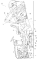
図1は、本発明の実施例に係る草刈装置20が装備された乗用型草刈機の全体側面図である。この図に示すように、この乗用型草刈機は、左右一対の操向操作自在な前車輪1,1と左右一対の駆動自在な後車輪2,2とによって自走するよう構成され、かつ車体後部に設けた運転座席3が装備された運転部を有した乗用型の自走車と、この自走車の車体フレーム4の前後輪間にリンク機構10を介して連結された本発明の実施例に係る草刈装置20と、前記車体フレーム4の後部に支持フレーム31を介して連結された集草容器32を有した刈草回収装置30とを備えている。
Embodiments of the present invention will be described below with reference to the drawings.
FIG. 1 is an overall side view of a riding mower equipped with a
この作業車は、芝や草を刈り込む草刈り作業を行う。
すなわち、前記自走車は、車体フレーム4の前部に設けたエンジン5と、このエンジン5の下方に設けた動力取り出し機構40とを備えている。前記動力取り出し機構40は、前記エンジン5の出力を、伝動ベルト42を介して入力軸41に入力し、入力軸41の駆動力を油圧操作式の作業クラッチ45を介して動力取り出し軸43に伝達し、この動力取り出し軸43の駆動力を、回転軸46を介して前記草刈装置20の刈り刃駆動機構22に伝達する。
This work vehicle performs mowing work for cutting grass and grass.
That is, the self-propelled vehicle includes an
前記リンク機構10は、車体フレーム4に上下揺動自在に支持された左右一対の前揺動リンク11,11と、車体フレーム4に上下揺動自在に支持された左右一対の後揺動リンク12,12と、左右一対の連動リンク13,13とを備えている。
The
前記左右一対の前揺動リンク11,11の先端部は、草刈装置20の刈り刃ハウジング21の前部に位置する前連結部材23に連結されている。前記左右一対の後揺動リンク12,12の先端部は、前記刈り刃ハウジング21の後部に位置する後連結部材24に連結されている。前記左側の連動リンク13は、前記左側の前揺動リンク11と後揺動リンク12とを連動させ、前記右側の連動リンク13は、前記右側の前揺動リンク11と後揺動リンク13とを連動させている。前記左右一対の前揺動リンク11,11の一方にリフトシリンダ15が連動されている。
The front ends of the pair of left and right front swing links 11, 11 are connected to a
つまり、前記リンク機構10は、前記リフトシリンダ15によって一方の前揺動リンク11が揺動操作されると、左右一対の前揺動リンク11,11が回転支軸14による連動のために一体に揺動することによって車体フレーム4に対して上下に揺動操作され、草刈装置20を刈り刃ハウジング21の前後側に支持された接地ゲージ輪25が地面に接地した下降作業状態と、前記各接地ゲージ輪25が地面から上昇した上昇非作業状態とに昇降操作する。
In other words, when one of the front swing links 11 is swung by the
前記草刈装置20を下降作業状態にして自走車を走行させると、草刈装置20は、前記刈り刃ハウジング21の内部に刈り刃ハウジング横方向に並んで位置する二枚の刈り刃26を前記刈り刃駆動機構22によって刈り刃ハウジング上下向きの軸芯まわりに回転駆動して前記各刈り刃26によって草刈りを行い、刈り草を前記刈り刃26の回転によって発生した風によって刈り刃ハウジング21の上部に位置する刈り草排出ダクト27から車体後方上方向きに排出する。
When the self-propelled vehicle is driven with the
前記刈り草排出ダクト27から排出された刈り草は、前記刈り刃26からの風による搬送作用と、自走車に前記左右一対の後車輪2,2の間を車体前後方向に通して設けてある搬送ダクト6による案内作用とによって前記集草容器32に送り込まれ、この集草容器32によって回収されて貯留される。
The cut grass discharged from the cut
前記刈草回収装置30は、前記支持フレーム31と集草容器32とを連結するリンク機構33を昇降シリンダ34によって支持フレーム31に対して上下に揺動操作し、これによって集草容器32を下降集草位置と上昇排出位置とに昇降操作する。
The mowing
次に、前記草刈装置20についてさらに詳述する。
Next, the
図2,3,4に示すように、前記刈り刃ハウジング21は、天板21aとこの天板21aの周縁部に連設された側板21bとによって刈り刃ハウジング21の内部に刈り刃ハウジング横方向に並べて形成された一対の刈り室28,28と、前記天板21aに切り欠き孔を設けて形成した刈り草排出口29とを備えている。
As shown in FIGS. 2, 3, and 4, the
前記一対の刈り室28,28は、刈り刃ハウジング21の下端側で地面に向かって開口し、かつ刈り刃ハウジング21の横幅方向での中央部に位置する箇所で互いに隣り合って連通し合っている。前記刈り草排出口29は、前記一対の刈り室28,28が隣り合った部位の上方に位置して各刈り室28に連通している。
The pair of mowing
前記二つの刈り刃26,26は、前記各刈り室28に一つずつ位置する配置で備えられている。各刈り刃26は、刈り刃ハウジング21の天板21aを貫通した回転支軸26aに一体回転自在に支持されおり、前記回転支軸26aが備える刈り刃ハウジング上下向き軸芯まわりに前記刈り刃駆動機構22によって回転駆動される。
The two
前記刈り刃駆動機構22は、前記回転軸46に連動された入力軸22aの駆動力をベベルギヤ22bと平歯車22cとを利用して前記各回転支軸26aに伝達する。
The cutting
図2,3,4に示すように、前記刈り草排出ダクト27は、前記刈り刃ハウジング21に前記刈り草排出口29の両横側で板金を付設して設けたダクト下部構成体50と前記刈り刃ハウジング21の前端部に設けた左右一対の支持部21c、21cに枢支ピン51を介して連結部52aが連結されたダクト上部構成体52とを備えて構成してある。前記左右一対のダクト下部構成体50,50は、両ダクト下部構成体50,50の後端側の下部どうしにわたって連結した後部ガイド板53を備えている。
As shown in FIGS. 2, 3, and 4, the cut
図5は、前記ダクト上部構成体52の斜視図である。この図に示すように、前記ダクト上部構成体52は、左右一対の横側板52b、52bと、左右一対の横側板52b、52bの上端部に連なる天板52cとを備えている。
FIG. 5 is a perspective view of the duct
つまり、前記刈り草排出ダクト27は、前記左右一対のダクト下部構成体50,50によって刈り草排出ダクト27の左または右側の横側板の下部を構成され、前記ダクト上部構成体52によって刈り草排出ダクト27の左右の横側板の上部と天板とが構成され、前記刈り草排出口29からの刈り草をダクト下部構成体50とダクト上部構成体52とによって刈り刃ハウジング21の後方上方向きに流動案内して搬送ダクト6に供給する。
That is, in the cut
前記ダクト上部構成体52は、前記左右一対の枢支ピン51,51の軸芯で成る刈り刃ハウジング横向きの昇降軸芯まわりに刈り刃ハウジング21に対して上下揺動する。刈り刃ハウジング21は、前記ダクト上部構成体52の両横側で天板21aに立設したロッド形のバネホルダー55と、各バネホルダー55に支持させたコイルバネで成る上昇操作バネ56とを備えている。前記各上昇操作バネ56は、前記バネホルダー55に摺動自在に外嵌するよう構成してダクト上部構成体52の横側板52bに設けたバネ受け体57(図5参照)に作用してダクト上部構成体52を枢支ピン51の軸芯まわりに上昇付勢する。
つまり、刈り草排出ダクト27は、草刈装置20の自走車体に対する昇降による刈り刃ハウジング21と搬送ダクト6との上下間隔の変化にかかわらず、ダクト上部構成体52の上昇操作バネ56による上昇付勢によってダクト上部構成体52の後端側が搬送ダクト6の内面に当接した状態に維持され、刈り草排出口29からの刈り草を刈り草排出ダクト27と搬送ダクト6との間から漏れ出ないようにして搬送ダクト6に供給する。
The duct
That is, the cut
前記ダクト上部構成体52は、前記左右一対の枢支ピン51,51を前記支持部21cに対して脱着操作し、前記左右一対のバネ受け体57を前記バネホルダー55に対して係脱操作することにより、刈り刃ハウジング21に装着したり、刈り刃ハウジング21から取り外したりできる。
The duct
前記草刈装置20は、図6に示す蓋体60を刈り刃ハウジング21および前記刈り草排出ダクト27とは別部品に構成した状態で備えている。この図に示すように、前記蓋体60は、蓋体上下方向視で矩形の蓋体本体61と、この蓋体本体61の前端部に蓋体本体61の表面側に突出する左右一対の板体を一体成形して設けた左右一対の連結部62,62と、前記蓋体本体61の後端部の裏面側に屈曲板金を付設して設けた後部バッフルプレート63とを備えている。
The
前記左右一対の連結部62,62は、刈り刃ハウジング21の前記左右一対の支持部21c,21cに前記ダクト上部構成体52の前記連結部52aに替えて前記枢支ピン51によって脱着できる。
The pair of left and right connecting
図7,8に示すように、前記蓋体60は、前記左右一対の連結部62,62を刈り刃ハウジング21の前記支持部21cに前記枢支ピン51によって連結し、蓋体本体61の後端側に設けた連結孔61aと、前記左右一対のダクト下部構成体50,50に連結された支持体65とに連結ボルトを装着して蓋体50の後端側をガイド下部構成体50に支持させると、使用取り付け状態になる。使用取り付け状態になった蓋体60は、蓋体本体61によって刈り刃ハウジング21の前記刈り草排出口29を閉じる。
As shown in FIGS. 7 and 8, the
使用取り付け状態になった蓋体60は、前記後部バップルプレート63を前記一対の刈り刃26,26の後側に位置させ、この後部バッフルプレート63によって前記一対の刈り室28,28の後部で前記刈り草排出口29に望んでいる部位に後側壁28aを形成する。
すなわち、後部バッフルプレート63の一端側63aによって一方の刈り室28の後側壁28aを形成し、後部バッフルプレート63の他端側63bによって他方の刈り室28の後側壁28aを形成する。
When the
That is, the
図7は、草刈装置20のマルチング作業状態での側面図である。図8は、草刈装置20のマルチング作業状態での平面図である。これらの図に示すように、草刈装置20は、前記ダクト上部構成体52に替えて前記蓋体60を連結することにより、マルチング作業状態になる。
すなわち、蓋体60を連結すると、一対の刈り室28,28の後部に蓋体60の後部バップルプレート63によって後側壁28aが形成され、各刈り室28において、刈り刃26による刈り草の持ち回りが行なわれやすくなって刈り草の刈り刃26による細断が精度よく行なわれる。刈り刃ハウジング21の刈り草排出口29が蓋体本体61によって閉じられて各刈り室28の刈り草が刈り草排出口29から排出されなくなり、各刈り室28で細断された刈り草が刈り室28の底から地面に落下排出される。
FIG. 7 is a side view of the
That is, when the
図2は、草刈装置20のディスチャージ作業状態での平面図である。図3は、草刈装置20のディスチャージ作業状態での側面図である。これらの図に示すように、草刈装置20は、前記蓋体60に替えて前記ダクト上部構成体52を連結することにより、ディスチャージ作業状態になる。
すなわち、ダクト上部構成体52を連結すると、一対の刈り室28,28の後部に前記後側壁28aが形成されなくて各刈り室28の刈り草が刈り草排出口29に流動しやすくなる。刈り草排出口29が開かれて各刈り室28の刈り草が刈り草排出口29から排出され、刈り草排出口29から排出された刈り草が刈り草排出ダクト27によって流動案内されて刈り刃ハウジング21の後方上方向きに排出される。
FIG. 2 is a plan view of the
That is, when the duct
図9は、別実施構造を備えた蓋体60の斜視図である。この図に示すように、別実施構造を備えた蓋体60と、図6に示した実施構造を備えた蓋体60とを比較すると、刈り刃ハウジング21に脱着自在に連結する点と、一対の刈り室28,28の後部に後側壁28aを形成する点と、刈り刃ハウジング21の刈り草排出口29を閉じる点とにおいて、別実施構造を備えた蓋体60と、図6に示した実施構造を備えた蓋体60とは、同じ構成を備えている。別実施構造を備えた蓋体60は、蓋本体61の裏面側に設けた仕切り壁64を備えている点において、図6に示した実施構造を備えた蓋体60と相違している。
FIG. 9 is a perspective view of a
図10は、草刈装置20の別実施構造の蓋体60が取り付けられた状態での側面図である。図11は、草刈装置20の別実施構造の蓋体60が取り付けられた状態での平面図である。これらの図に示すように、前記仕切り壁62は、蓋体60が刈り刃ハウジング21に連結されて刈り草排出口29を閉じた状態において、前記隣り合う一対の刈り室28,28の間に位置して一対の刈り室28,28を仕切り、各刈り室28における刈り刃26による刈り草の持ち回りをより容易にする。
FIG. 10 is a side view showing a state in which the
21 刈り刃ハウジング
26 刈り刃
27 刈り草排出ダクト
28 刈り室
28a 刈り室の後側壁
29 刈り草排出口
50 ダクト下部構成体
52 ダクト上部構成体
60 蓋体
61 蓋体本体
62 連結部
63 後部バッフルプレート
64 仕切り壁
21
Claims (5)
前記刈り草排出口を開閉する蓋体を備え、
前記蓋体が前記刈り草排出口を閉じた状態で前記隣り合う一対の刈り室で草刈り作用する刈り刃の後側に位置して前記隣り合う一対の刈り室の後側壁を形成する後部バッフルプレートを、前記蓋体に備えてある草刈装置。 A cutting blade that can be driven and rotated around the vertical axis of the cutting blade housing is arranged in the horizontal direction in the cutting blade housing, and a pair of cutting chambers adjacent to the cutting blade housing communicate with each other. A mowing apparatus provided with a cut grass outlet provided above the part,
A lid that opens and closes the cut grass outlet;
A rear baffle plate that is located on the rear side of a cutting blade that cuts grass in the pair of adjacent mowing chambers with the lid closing the cut grass discharge port and forms a rear wall of the pair of adjacent mowing chambers A mowing apparatus provided on the lid.
前記刈り草排出口から刈り刃ハウジング後方上方向きに延出する刈り草排出ダクトの下部を構成するよう前記刈り刃ハウジングに付設したダクト下部構成体と、前記刈り刃ハウジングに連結されることによって前記刈り草排出ダクトの上部を構成する脱着自在なダクト上部構成体とを備えてある請求項1又は2記載の草刈装置。 The lid is detachably provided,
By connecting to the cutting blade housing, a duct lower structure attached to the cutting blade housing so as to form a lower portion of a cutting grass discharge duct extending from the cutting grass discharge port to the rear upper direction of the cutting blade housing. The mowing apparatus according to claim 1 or 2, further comprising a detachable duct upper part constituting an upper part of the cut grass discharge duct.
前記刈り草排出口を開閉する蓋体本体と、
蓋体本体が前記刈り草排出口を閉じた状態で前記刈り刃ハウジングに支持されるよう前記刈り刃ハウジングに連結する脱着自在な連結部と、
前記蓋体本体が前記刈り草排出口を閉じた状態で前記隣り合う一対の刈り室で草刈り作用する刈り刃の後側に位置して前記隣り合う一対の刈り室の後側壁を形成する後部バッフルプレートを前記蓋体本体に備えてある蓋体。 A cutting blade that can be driven and rotated around the vertical axis of the cutting blade housing is arranged in the horizontal direction in the cutting blade housing, and a pair of cutting chambers adjacent to the cutting blade housing communicate with each other. A lid used for a mowing apparatus provided with a cut grass discharge port disposed above the site,
A lid body that opens and closes the cut grass outlet;
A detachable connecting portion for connecting to the cutting blade housing so that the lid body is supported by the cutting blade housing in a state where the cutting grass discharge port is closed;
A rear baffle forming a rear side wall of the pair of adjacent mowing chambers located on the rear side of the cutting blade that mows the pair of adjacent mowing chambers with the lid body closing the cut grass discharge port. A lid provided with a plate on the lid body.
Priority Applications (1)
| Application Number | Priority Date | Filing Date | Title |
|---|---|---|---|
| JP2008160752A JP5123750B2 (en) | 2008-06-19 | 2008-06-19 | Mowing equipment |
Applications Claiming Priority (1)
| Application Number | Priority Date | Filing Date | Title |
|---|---|---|---|
| JP2008160752A JP5123750B2 (en) | 2008-06-19 | 2008-06-19 | Mowing equipment |
Publications (2)
| Publication Number | Publication Date |
|---|---|
| JP2010000023A true JP2010000023A (en) | 2010-01-07 |
| JP5123750B2 JP5123750B2 (en) | 2013-01-23 |
Family
ID=41582269
Family Applications (1)
| Application Number | Title | Priority Date | Filing Date |
|---|---|---|---|
| JP2008160752A Expired - Fee Related JP5123750B2 (en) | 2008-06-19 | 2008-06-19 | Mowing equipment |
Country Status (1)
| Country | Link |
|---|---|
| JP (1) | JP5123750B2 (en) |
Cited By (4)
| Publication number | Priority date | Publication date | Assignee | Title |
|---|---|---|---|---|
| JP2015062402A (en) * | 2013-08-28 | 2015-04-09 | 井関農機株式会社 | Riding mower |
| EP3598887A3 (en) * | 2018-07-05 | 2020-04-22 | Kubota Corporation | Support carriage, riding grass mower having the support carriage, and work vehicle including the riding grass mower |
| JP2020078270A (en) * | 2018-11-13 | 2020-05-28 | 株式会社クボタ | Mower |
| EP3653041A3 (en) * | 2018-11-13 | 2020-08-05 | Kubota Corporation | Ridable mower machine |
Families Citing this family (1)
| Publication number | Priority date | Publication date | Assignee | Title |
|---|---|---|---|---|
| JP2023151837A (en) * | 2022-04-01 | 2023-10-16 | 井関農機株式会社 | mower |
Citations (4)
| Publication number | Priority date | Publication date | Assignee | Title |
|---|---|---|---|---|
| JPH08214660A (en) * | 1995-02-14 | 1996-08-27 | Kubota Corp | Mulching mower |
| JP2000004634A (en) * | 1998-06-18 | 2000-01-11 | Iseki & Co Ltd | Mower deck for blade mower |
| JP2005046063A (en) * | 2003-07-29 | 2005-02-24 | Iseki & Co Ltd | Lawn mower |
| JP2005312314A (en) * | 2004-04-27 | 2005-11-10 | Yanmar Co Ltd | Traveling type lawn mower |
-
2008
- 2008-06-19 JP JP2008160752A patent/JP5123750B2/en not_active Expired - Fee Related
Patent Citations (4)
| Publication number | Priority date | Publication date | Assignee | Title |
|---|---|---|---|---|
| JPH08214660A (en) * | 1995-02-14 | 1996-08-27 | Kubota Corp | Mulching mower |
| JP2000004634A (en) * | 1998-06-18 | 2000-01-11 | Iseki & Co Ltd | Mower deck for blade mower |
| JP2005046063A (en) * | 2003-07-29 | 2005-02-24 | Iseki & Co Ltd | Lawn mower |
| JP2005312314A (en) * | 2004-04-27 | 2005-11-10 | Yanmar Co Ltd | Traveling type lawn mower |
Cited By (6)
| Publication number | Priority date | Publication date | Assignee | Title |
|---|---|---|---|---|
| JP2015062402A (en) * | 2013-08-28 | 2015-04-09 | 井関農機株式会社 | Riding mower |
| EP3598887A3 (en) * | 2018-07-05 | 2020-04-22 | Kubota Corporation | Support carriage, riding grass mower having the support carriage, and work vehicle including the riding grass mower |
| EP3777511A1 (en) * | 2018-07-05 | 2021-02-17 | Kubota Corporation | Grass mower |
| JP2020078270A (en) * | 2018-11-13 | 2020-05-28 | 株式会社クボタ | Mower |
| EP3653041A3 (en) * | 2018-11-13 | 2020-08-05 | Kubota Corporation | Ridable mower machine |
| JP7023215B2 (en) | 2018-11-13 | 2022-02-21 | 株式会社クボタ | Mower |
Also Published As
| Publication number | Publication date |
|---|---|
| JP5123750B2 (en) | 2013-01-23 |
Similar Documents
| Publication | Publication Date | Title |
|---|---|---|
| EP2850932B1 (en) | Cutter blade for mower | |
| JP5123750B2 (en) | Mowing equipment | |
| JP5054611B2 (en) | Mower | |
| JP2009273386A (en) | Riding lawn mower | |
| JP5185842B2 (en) | Mowing equipment | |
| JP2004041058A (en) | Lawn mower | |
| JP2013126390A (en) | Corn harvester | |
| JP4546911B2 (en) | Rear discharge type mowing device | |
| JP5338457B2 (en) | Lawn mower mower deck | |
| JP4791932B2 (en) | Moore | |
| JP5139835B2 (en) | Moore | |
| JP6362841B2 (en) | Mower unit | |
| JP2012228200A (en) | Mower and mounting for mowing | |
| JP2007185129A (en) | Mower | |
| JP2001251924A (en) | Mower deck of blade mower | |
| JP2008283884A (en) | Working machine for weeding and weeder | |
| JP2012065569A (en) | Lawn mower | |
| JP4913566B2 (en) | Lawn mower | |
| JP2003189718A (en) | Grass-collecting structure for working machine | |
| JP5446073B2 (en) | Weeding and spreading work vehicle | |
| JP2007185128A (en) | Mower | |
| JP2008173052A (en) | Lift linking mechanism for mower | |
| JP2007124976A (en) | Riding lawn mower | |
| JP2023127158A (en) | Sulky lawn mower | |
| JP3783460B2 (en) | Rear discharge mower grass cutting device |
Legal Events
| Date | Code | Title | Description |
|---|---|---|---|
| A621 | Written request for application examination |
Free format text: JAPANESE INTERMEDIATE CODE: A621 Effective date: 20100927 |
|
| A977 | Report on retrieval |
Free format text: JAPANESE INTERMEDIATE CODE: A971007 Effective date: 20120221 |
|
| A131 | Notification of reasons for refusal |
Free format text: JAPANESE INTERMEDIATE CODE: A131 Effective date: 20120223 |
|
| A521 | Written amendment |
Free format text: JAPANESE INTERMEDIATE CODE: A523 Effective date: 20120420 |
|
| A131 | Notification of reasons for refusal |
Free format text: JAPANESE INTERMEDIATE CODE: A131 Effective date: 20120628 |
|
| A521 | Written amendment |
Free format text: JAPANESE INTERMEDIATE CODE: A523 Effective date: 20120802 |
|
| TRDD | Decision of grant or rejection written | ||
| A01 | Written decision to grant a patent or to grant a registration (utility model) |
Free format text: JAPANESE INTERMEDIATE CODE: A01 Effective date: 20120927 |
|
| A01 | Written decision to grant a patent or to grant a registration (utility model) |
Free format text: JAPANESE INTERMEDIATE CODE: A01 |
|
| A61 | First payment of annual fees (during grant procedure) |
Free format text: JAPANESE INTERMEDIATE CODE: A61 Effective date: 20121026 |
|
| FPAY | Renewal fee payment (event date is renewal date of database) |
Free format text: PAYMENT UNTIL: 20151102 Year of fee payment: 3 |
|
| R150 | Certificate of patent or registration of utility model |
Free format text: JAPANESE INTERMEDIATE CODE: R150 Ref document number: 5123750 Country of ref document: JP Free format text: JAPANESE INTERMEDIATE CODE: R150 |
|
| LAPS | Cancellation because of no payment of annual fees |