JP2009545338A - Medical device for tissue resection - Google Patents
Medical device for tissue resection Download PDFInfo
- Publication number
- JP2009545338A JP2009545338A JP2009518993A JP2009518993A JP2009545338A JP 2009545338 A JP2009545338 A JP 2009545338A JP 2009518993 A JP2009518993 A JP 2009518993A JP 2009518993 A JP2009518993 A JP 2009518993A JP 2009545338 A JP2009545338 A JP 2009545338A
- Authority
- JP
- Japan
- Prior art keywords
- head
- tip
- guide member
- cutting
- ablation
- Prior art date
- Legal status (The legal status is an assumption and is not a legal conclusion. Google has not performed a legal analysis and makes no representation as to the accuracy of the status listed.)
- Pending
Links
Images


Classifications
-
- A—HUMAN NECESSITIES
- A61—MEDICAL OR VETERINARY SCIENCE; HYGIENE
- A61B—DIAGNOSIS; SURGERY; IDENTIFICATION
- A61B18/00—Surgical instruments, devices or methods for transferring non-mechanical forms of energy to or from the body
- A61B18/04—Surgical instruments, devices or methods for transferring non-mechanical forms of energy to or from the body by heating
- A61B18/12—Surgical instruments, devices or methods for transferring non-mechanical forms of energy to or from the body by heating by passing a current through the tissue to be heated, e.g. high-frequency current
- A61B18/14—Probes or electrodes therefor
- A61B18/1492—Probes or electrodes therefor having a flexible, catheter-like structure, e.g. for heart ablation
-
- A—HUMAN NECESSITIES
- A61—MEDICAL OR VETERINARY SCIENCE; HYGIENE
- A61B—DIAGNOSIS; SURGERY; IDENTIFICATION
- A61B5/00—Measuring for diagnostic purposes; Identification of persons
- A61B5/42—Detecting, measuring or recording for evaluating the gastrointestinal, the endocrine or the exocrine systems
- A61B5/4222—Evaluating particular parts, e.g. particular organs
- A61B5/4233—Evaluating particular parts, e.g. particular organs oesophagus
-
- A—HUMAN NECESSITIES
- A61—MEDICAL OR VETERINARY SCIENCE; HYGIENE
- A61B—DIAGNOSIS; SURGERY; IDENTIFICATION
- A61B5/00—Measuring for diagnostic purposes; Identification of persons
- A61B5/68—Arrangements of detecting, measuring or recording means, e.g. sensors, in relation to patient
- A61B5/6846—Arrangements of detecting, measuring or recording means, e.g. sensors, in relation to patient specially adapted to be brought in contact with an internal body part, i.e. invasive
- A61B5/6885—Monitoring or controlling sensor contact pressure
-
- A—HUMAN NECESSITIES
- A61—MEDICAL OR VETERINARY SCIENCE; HYGIENE
- A61M—DEVICES FOR INTRODUCING MEDIA INTO, OR ONTO, THE BODY; DEVICES FOR TRANSDUCING BODY MEDIA OR FOR TAKING MEDIA FROM THE BODY; DEVICES FOR PRODUCING OR ENDING SLEEP OR STUPOR
- A61M25/00—Catheters; Hollow probes
- A61M25/01—Introducing, guiding, advancing, emplacing or holding catheters
- A61M25/0105—Steering means as part of the catheter or advancing means; Markers for positioning
- A61M25/0127—Magnetic means; Magnetic markers
-
- A—HUMAN NECESSITIES
- A61—MEDICAL OR VETERINARY SCIENCE; HYGIENE
- A61B—DIAGNOSIS; SURGERY; IDENTIFICATION
- A61B18/00—Surgical instruments, devices or methods for transferring non-mechanical forms of energy to or from the body
- A61B2018/00315—Surgical instruments, devices or methods for transferring non-mechanical forms of energy to or from the body for treatment of particular body parts
- A61B2018/00345—Vascular system
- A61B2018/00351—Heart
-
- A—HUMAN NECESSITIES
- A61—MEDICAL OR VETERINARY SCIENCE; HYGIENE
- A61B—DIAGNOSIS; SURGERY; IDENTIFICATION
- A61B18/00—Surgical instruments, devices or methods for transferring non-mechanical forms of energy to or from the body
- A61B2018/00571—Surgical instruments, devices or methods for transferring non-mechanical forms of energy to or from the body for achieving a particular surgical effect
- A61B2018/00577—Ablation
-
- A—HUMAN NECESSITIES
- A61—MEDICAL OR VETERINARY SCIENCE; HYGIENE
- A61B—DIAGNOSIS; SURGERY; IDENTIFICATION
- A61B18/00—Surgical instruments, devices or methods for transferring non-mechanical forms of energy to or from the body
- A61B2018/00636—Sensing and controlling the application of energy
- A61B2018/00642—Sensing and controlling the application of energy with feedback, i.e. closed loop control
-
- A—HUMAN NECESSITIES
- A61—MEDICAL OR VETERINARY SCIENCE; HYGIENE
- A61B—DIAGNOSIS; SURGERY; IDENTIFICATION
- A61B34/00—Computer-aided surgery; Manipulators or robots specially adapted for use in surgery
- A61B34/20—Surgical navigation systems; Devices for tracking or guiding surgical instruments, e.g. for frameless stereotaxis
- A61B2034/2046—Tracking techniques
- A61B2034/2051—Electromagnetic tracking systems
Abstract
本発明による心腔(22)内の組織を切除するための医療装置は、患者の食道(21)内に導入されるように構成された案内部材と、カテーテルの遠位端部又は遠位先端部に取付けられた切除電極を備えた切除部材とを有する。案内部材のヘッド(2)と切除部材の先端部は、両方とも磁化され(12,15)、それらの遠位端部を近づけると、磁気的に結合する。いったん磁気的結合を達成したら、案内部材を移動させることによって、切除部材の先端部を案内する。案内部材は、治療中に生理的パラメータを監視することを可能にするセンサ(20,23)を含むことが好ましい。本発明の更なる目的は、治療中に切除先端部を案内する方法に関する。 A medical device for excising tissue in a heart chamber (22) according to the present invention comprises a guide member configured to be introduced into a patient's esophagus (21) and a distal end or distal tip of a catheter. And an ablation member having an ablation electrode attached to the part. Both the head (2) of the guide member and the tip of the cutting member are magnetized (12, 15) and are magnetically coupled when their distal ends are brought close together. Once magnetic coupling is achieved, the tip of the ablation member is guided by moving the guide member. The guide member preferably includes sensors (20, 23) that allow monitoring of physiological parameters during treatment. A further object of the invention relates to a method for guiding a cutting tip during treatment.
Description
本発明は心腔内の連続した線に沿って心臓組織を切除するための改善された医療装置又は機器に関する。本発明の更なる目的は、切除手術中、切除カテーテルを位置決めし、案内する方法に関する。より詳細には、本発明の装置及び方法は、心房細動の発生を治療して防止するために、左心房の後壁に切除線を実施するように構成される。その範囲において、医療装置は、切除電極を備えた遠位端部を有する細長い部材と、切除電極の正確な制御を可能にする第2の細長い部材即ち案内部材とを有する。 The present invention relates to an improved medical device or apparatus for ablating heart tissue along a continuous line in a heart chamber. A further object of the present invention relates to a method for positioning and guiding an ablation catheter during ablation surgery. More particularly, the devices and methods of the present invention are configured to perform ablation on the posterior wall of the left atrium to treat and prevent the occurrence of atrial fibrillation. To that extent, the medical device has an elongate member having a distal end with an ablation electrode and a second elongate member or guide member that allows for precise control of the ablation electrode.
異常な心拍リズムは、一般に、心不整脈と呼ばれ、異常に速いリズムを伴う場合には頻脈と呼ばれる。心房細動は、心房と呼ばれる心臓の2つの上部心腔内における異常な放電によって引起こされる心臓の異常リズムである。心房細動は、血液を心臓の下部心腔(心室)にポンプ送りする心房の能力を低下させ、普通、心臓に速すぎる拍動を生じさせ、心不全及び心臓発作を含む合併症を誘発させることがある。 An abnormal heart rhythm is generally called cardiac arrhythmia, and is called tachycardia when accompanied by an abnormally fast rhythm. Atrial fibrillation is an abnormal rhythm of the heart caused by abnormal discharges in the two upper chambers of the heart called the atria. Atrial fibrillation reduces the ability of the atrium to pump blood into the lower heart chamber (ventricle) of the heart, usually causing too fast a beat in the heart and inducing complications including heart failure and heart attack There is.
心房細動の再発を防ぐための薬物が用いられてきたけれども、薬物は常に有効とは限らず、また望ましくない又は耐えられない副作用を誘発させることがある。さらに、薬物は、根本的な原因を治療するものではない。埋込み式の装置も用いられているが、かかる装置は、不整脈が起こった後にそれを矯正するだけで、不整脈を防ぐ助けにはならない。 Although drugs have been used to prevent recurrence of atrial fibrillation, the drugs are not always effective and may cause undesirable or intolerable side effects. Furthermore, drugs do not treat the root cause. Implantable devices are also used, but such devices only correct the arrhythmia after it occurs and do not help prevent the arrhythmia.
対照的に、外科的で侵襲的なカテーテル手法は、細動を誘発させる電気的不良を引起こす心臓組織の一部分を切除することによって疾患を治療するので、有望であり非常に良好な結果をもたらしている。 In contrast, surgical and invasive catheterization techniques have promising and very good results because they treat the disease by excising a portion of the heart tissue that causes electrical failure that induces fibrillation. ing.
心房の内壁のある部分の切除を実施する前に、心臓内の異常電気経路を突き止めると共に心臓活動の他の力学的特徴を検出するために、まず、心臓マッピングが実行される。心臓の正確なマッピングを構築するための種々の方法及び装置が開示され、一般に用いられており、それを本明細書では更に説明しない。いったん心臓マッピングを行ったら、臨床医は、心臓マッピングを参照し、心臓マッピングは、切除を実施すべき箇所及び線を臨床医に指示する。 Before performing an excision of a portion of the inner wall of the atrium, cardiac mapping is first performed to locate abnormal electrical pathways in the heart and detect other mechanical features of cardiac activity. Various methods and devices for constructing an accurate mapping of the heart have been disclosed and are in general use and will not be further described herein. Once the cardiac mapping has been performed, the clinician refers to the cardiac mapping, which instructs the clinician where and where the ablation should be performed.
切除を実施するために一般に用いられる1つの技術は、無線周波数カテーテル切除として知られている。この技術は、カテーテルの遠位端部に取付けられた切除電極を用い、カテーテルの遠位端部を生来の通路を通して目標心腔内に導入し、次に、外科医が、操縦機構に作用するカテーテルの近位端のハンドルによって、カテーテルの遠位端部を操作する。これにより、心臓マッピング技術及び/又は蛍光透視法によって決定される正確な位置に切除電極を配置させるように、カテーテルの遠位端部を移動させる。いったん切除電極を予め決められた領域に接触させたら、無線周波数エネルギーを加えて、心臓組織を切除する。心臓組織の予め決められた部分に首尾よく損傷を生じさせることにより、心房細動の原因である異常電気的パターンを取除く。 One technique commonly used to perform ablation is known as radio frequency catheter ablation. This technique uses an ablation electrode attached to the distal end of the catheter, introduces the distal end of the catheter through the natural passageway into the target heart chamber, and then the surgeon acts on the steering mechanism. The distal end of the catheter is manipulated by the proximal end handle. This moves the distal end of the catheter so as to place the ablation electrode at the exact location determined by cardiac mapping techniques and / or fluoroscopy. Once the ablation electrode is in contact with the predetermined area, radio frequency energy is applied to ablate the heart tissue. By successfully damaging a predetermined portion of the heart tissue, the abnormal electrical pattern responsible for atrial fibrillation is removed.
しかしながら、この技術は幾つかの困難を有する。現在用いられている手作業によるカテーテル切除、及び、開発中のロボット切除システムの技術は、心房壁内面に沿って正確に制御された切除電極先端部の移動を可能にしない。カテーテルの遠位端部に位置する切除電極は、直線に従ってではなく、1つの箇所から別の箇所にスリップしたり及びジャンプしたりすることが多い。治療中、心房壁のリアルタイムの可視化がないと、正確な連続切除線の生成が妨げられる。切除箇所と切除箇所の間の途切れは、一般に効率の欠如をもたらし、心房粗動の発生を誘発させることがある。 However, this technique has some difficulties. The currently used manual catheter ablation and robot ablation system technologies under development do not allow for precisely controlled ablation electrode tip movement along the inner surface of the atrial wall. The ablation electrode located at the distal end of the catheter often slips and jumps from one location to another rather than following a straight line. During treatment, the lack of real-time visualization of the atrial wall prevents the generation of accurate continuous ablation lines. Discontinuities between excision sites generally result in a lack of efficiency and can trigger the occurrence of atrial flutter.
別の知られている問題は、切除損傷の深さを正確に制御するために、切除先端部に送られる正しいエネルギーレベルを決定することに関する。カテーテルの遠位端部が正しく配置されていない場合、又は、切除電極が心臓組織に対して垂直でない場合、加えるエネルギーが低すぎて損傷が無効であったり、加えるエネルギーが高すぎて稀に食道熱傷及び心房から食道への瘻孔を形成したりすることがある。この合併症は、稀ではあるが、報告された事例の半数を超える事例において極めて破壊的であり致命的である。 Another known problem relates to determining the correct energy level delivered to the ablation tip in order to accurately control the depth of the ablation injury. If the distal end of the catheter is not properly positioned, or if the ablation electrode is not perpendicular to the heart tissue, the applied energy is too low and the damage is ineffective, or the applied energy is too high and rarely the esophagus May cause burns and a fistula from the atria to the esophagus. This complication is rare but extremely devastating and fatal in more than half of the reported cases.
カテーテル先端部において切除電極の近傍に温度センサを用いることは、この問題を解決する助けにならない。その理由は、温度センサの測定は、殆どの場合、無線周波数エネルギーを加えたときの切除電極の加熱による影響を受け、温度センサが組織温度の正確な測定を行わないからである。 Using a temperature sensor near the ablation electrode at the catheter tip does not help to solve this problem. This is because the temperature sensor measurement is most often affected by the heating of the ablation electrode when radio frequency energy is applied, and the temperature sensor does not accurately measure the tissue temperature.
本発明の目的は、治療中の切除電極の配置及び移動の正確な制御を可能にする医療装置又は機器、及び方法を提供すること、及び適切な生理的パラメータを効果的に監視して、上述の恐ろしい合併症の発生を防ぎ又はなくすことにある。 It is an object of the present invention to provide a medical device or device and method that allows precise control of the placement and movement of an ablation electrode during treatment, and to monitor appropriate physiological parameters effectively, as described above. It is to prevent or eliminate the occurrence of terrible complications.
本発明の目的は、請求項1に記載された特徴を有する医療機器、及び、請求項12に記載された心腔壁のある部分の切除治療中に切除電極を案内する方法によって達成される。
The object of the invention is achieved by a medical device having the features as defined in claim 1 and a method according to
本発明の目的である医療機器及び方法の他の特徴は、従属請求項に記載される。 Other features of the medical device and method that are the object of the present invention are described in the dependent claims.
本発明の1つ又はそれ以上の実施形態の詳細は、添付の図面及び以下の説明において示される。本発明の他の特徴、目的、及び利点は、以下の詳細な説明及び添付の図面から明らかとなるであろう。 The details of one or more embodiments of the invention are set forth in the accompanying drawings and the description below. Other features, objects, and advantages of the present invention will become apparent from the following detailed description and the accompanying drawings.
概略的には、本発明の目的である医療装置は、例えば、遠位端部及び近位端を有し且つカテーテル法等の既知の技術によって生来の通路を通して人体内に導入されるように構成された2つの異なる細長い部材を有する。2つの細長い部材の両遠位端部は、磁石又は磁石の配列を有し、従って、それらを互いに近づけると、それらを磁気的に結合させることができる。細長い部材の各々は、人体の異なる腔に導入されるように構成され、従って、2つの細長い部材の遠位端部の間の磁気的結合は、常に、内臓器官の壁を介して生じることに注意すべきである。一例として、細長い部材のうちの一方は、患者の1つの心腔に導入され、第2の細長い部材、即ち、案内部材は、食道に導入される。もちろん、他の組合せも、後で説明するように可能である。一方の細長い部材の遠位端部は、磁石又は磁石の配列に加えて、人体組織を切除する手段を有する。第2の細長い部材の遠位端部は、両遠位端部が磁気的に結合したときに、切除すべき組織の反対側の温度を監視する温度センサを有する。2つの細長い部材のうちの少なくとも一方は、その遠位端部を種々の方向に移動させるための手段を有することが好ましい。そのような手段は、一例を挙げれば、近位端から遠位端部まで延び、従来の生物医学的カテーテルのように近位端に設けられたハンドルによって作動させることが可能な操縦機構に接続されるワイヤである。更なる実施形態では、両部材の遠位端部は、適切な手段によって独立に操作することができる。以下の開示において、本発明による医療装置は、左心房の内壁のある部分の切除に関連した好ましい実施形態を説明する。本発明の精神から逸脱することなしに、同じ原理に従って実施することが可能な多くの他の治療法がありうることは明白である。 In general, a medical device that is an object of the present invention has a distal end and a proximal end and is configured to be introduced into the human body through a natural passage by known techniques such as catheterization. Having two different elongated members. Both distal ends of the two elongate members have a magnet or an array of magnets so that they can be magnetically coupled when they are brought close together. Each elongate member is configured to be introduced into a different cavity of the human body, so that the magnetic coupling between the distal ends of the two elongate members always occurs through the wall of the internal organ. You should be careful. As an example, one of the elongate members is introduced into one heart chamber of the patient, and the second elongate member, i.e. the guide member, is introduced into the esophagus. Of course, other combinations are possible as will be described later. The distal end of one elongate member has means for ablating human tissue in addition to a magnet or array of magnets. The distal end of the second elongate member has a temperature sensor that monitors the temperature opposite the tissue to be ablated when both distal ends are magnetically coupled. Preferably, at least one of the two elongate members has means for moving its distal end in various directions. Such means, for example, extend from the proximal end to the distal end and connect to a steering mechanism that can be actuated by a handle provided at the proximal end, like a conventional biomedical catheter. Wire to be used. In further embodiments, the distal ends of both members can be independently manipulated by suitable means. In the following disclosure, a medical device according to the present invention describes a preferred embodiment related to resection of a portion of the inner wall of the left atrium. It will be apparent that there can be many other therapies that can be performed according to the same principles without departing from the spirit of the invention.
解剖学的観察によれば、食道は、左心房後壁上縁のレベルで左心房外壁と接し、下肺静脈のレベルを超えて接している。従って、本発明の1つの目的は、患者の食道に導入され、次いで、心房内にある切除電極に食道壁及び心房壁を介して磁力によって結合される案内部材を用いて、心腔内に配置された切除カテーテルを案内することにある。その範囲において、本発明の目的である医療機器は、2つの異なる細長い部材を有する。 According to anatomical observations, the esophagus touches the left atrial outer wall at the level of the upper edge of the left atrial posterior wall and touches the level of the lower pulmonary vein. Accordingly, one object of the present invention is to be placed in the heart chamber using a guide member that is introduced into the patient's esophagus and then magnetically coupled to the ablation electrode in the atrium via the esophageal and atrial walls. To guide the ablated catheter. To that extent, the medical device that is the object of the present invention has two different elongate members.
第1の部材、即ち、切除部材は、その遠位端部に、切除手段を有し、この切除手段は、例えば、心房内で組織切除を行うように適合させた無線周波数発生器に接続された電極である。第2の部材、即ち、案内部材は、カテーテルチューブで構成され、このカテーテルチューブは、口又は鼻を通して患者の食道に導入され、左心房の近傍にある食道部分内に案内されるように構成される。両部材の遠位端部は、両部材の遠位端部が近づいたときに食道及び心房の両方の壁を介して磁気的に結合することを可能にする少なくとも1つの磁石又は磁石の配列を有する。いったん磁気的結合を達成したら、患者の食道内の案内部材を用いて、切除部材を予め決められた軌道に沿って案内し、心臓組織を切除する。 The first member, i.e., the ablation member, has an ablation means at its distal end, which is connected to a radio frequency generator adapted to perform tissue ablation, e.g., in the atrium. Electrode. The second member, i.e., the guide member, is composed of a catheter tube that is configured to be introduced into the patient's esophagus through the mouth or nose and guided into the portion of the esophagus near the left atrium. The The distal ends of both members have at least one magnet or arrangement of magnets that allows them to be magnetically coupled through both the esophageal and atrial walls when the distal ends of both members are approached. Have. Once magnetic coupling is achieved, a guide member in the patient's esophagus is used to guide the ablation member along a predetermined trajectory and ablate the heart tissue.
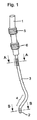
図1を参照すると、人体の食道に導入されるように構成された案内部材が、近位端部に配置されたハンドル1と、遠位端部とを有し、この遠位端部は、ヘッド2としても参照される。可撓性の中空プラスチックチューブ3は、近位端部と遠位端部とを接続する。チューブ3の下側部分4は、可撓性プラスチック材料で作られ、案内部材の遠位端部、即ち、ヘッド2を組込んでいる。この案内部材のハンドル1は、更に、操縦機構を有し、この操縦機構は、カテーテルチューブの下側部分4、従って、ヘッド2を種々の方向に移動させることを可能にする2つの回転コマンドボタン5、6を有している。カテーテルチューブ3の上側部分は、等間隔のマーカーを有し、このマーカーは、患者の食道内へのカテーテルの前進の距離/患者の食道からのカテーテルの後退の距離、従って、患者の食道内での遠位ヘッド2の長手方向の移動を視覚的に認識するのに用いられる。
Referring to FIG. 1, a guide member configured to be introduced into the human esophagus has a handle 1 disposed at the proximal end and a distal end, the distal end being Also referred to as
図2は、図1の線A−Aにおける断面図であり、コマンドボタン5、6に接続され且つカテーテルヘッド2まで延びる4つのワイヤ7、8、9、10を示す。コマンドボタン5、6の回転により作動されるこれらのワイヤは、可撓性部分4に張力を伝えることを可能にすると共に、カテーテルヘッド2の曲げを異なる面内において可能にする。
FIG. 2 is a cross-sectional view taken along line AA in FIG. 1 and shows four
案内部材の遠位端部、即ち、カテーテルヘッド2は、後で説明する少なくとも1つの永久磁石、又は、永久磁石の配列を有する磁化部分を有している。
The distal end of the guide member, i.e., the
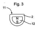
図3は、図1の線B−Bにおける食道カテーテルヘッド2の断面図であり、永久磁石12のN極及びS極を示す。永久磁石12は、カテーテルチューブ3の遠位端部のところでプラスチックヘッド2に完全に組込まれ、従って、カテーテルヘッド2は、電気的に絶縁されている。次の段落において分かるように、案内部材の磁化された遠位ヘッド2は、それに対応する切除部材の磁化された端部に結合され、それと協働するように構成され、従って、切除のために無線周波数エネルギーを用いる場合、案内部材のヘッド2が電気的に絶縁されていることが重要である。この場合、絶縁されていないと、案内部材ヘッド2の望ましくない加熱を生じさせる容量性電流の生成を引起こすことがあり、食道壁への熱傷の危険がある。案内部材ヘッド2は、治療中に食道の内壁に当接するように構成された少なくとも1つの平坦面11を有するように形状決めされることが好ましい。案内部材ヘッド2の変形形態が図4に示され、図4は、後述する円筒形切除先端部のより良好なドッキング又は結合を可能にするように平坦面11内に配置された半円筒形状の凹部13を示す。
FIG. 3 is a cross-sectional view of the
本発明の目的である医療装置は、切除を行うための適当な部材、即ち、切除部材を有し、切除部材は、例えば、近位端部と遠位端部と両端部の間に延びる管腔とを有するカテーテルの遠位端部に取付けられた少なくとも1つの通常の切除電極として構成される。少なくとも1つの切除電極を含む無線周波数(RF)切除プローブが、切除部材の遠位端部の終端に配置され、必要な場合、医師が、近位端部に配置されたハンドルの作動によって、又は、外部シースの移動又は曲げられた内部コアワイヤによって、切除プローブを操作する。切除カテーテル装置の作動原理は、当該技術分野においてよく知られており、係る作動原理を本出願においてさらに詳細に説明しない。本発明では、単極及び2極の切除カテーテルの両方が用いられてもよい。 The medical device which is the object of the present invention has a suitable member for performing ablation, i.e. a resection member, for example a tube extending between the proximal end and the distal end and both ends. Configured as at least one conventional ablation electrode attached to the distal end of the catheter having a lumen. A radio frequency (RF) ablation probe including at least one ablation electrode is placed at the end of the distal end of the ablation member and, if necessary, by the actuation of a handle located at the proximal end, or The ablation probe is manipulated by moving the outer sheath or bending the inner core wire. The operating principles of ablation catheter devices are well known in the art and will not be described in further detail in this application. In the present invention, both monopolar and bipolar ablation catheters may be used.
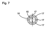
図5は、切除部材の遠位端部を概略的に示し、遠位端部は、切除部材の先端部14としても参照される。先端部14は、永久磁石15を組込み、そのN極とS極を、それに対応するNとSの文字で示す。切除部材の先端部14の形状は一般に円筒形であるが、他の形状を有していてもよく、永久磁石15と在来の切除電極の両方を組込んでいる。切除部材の先端部14は、可撓性プラスチックチューブ16に取付けられ、導電性ワイヤ17により、切除電極に電流を送ることを可能にする。変形例では、先端部14とチューブ16の遠位部分は、1つより多くの切除電極及び/又はセンサ電極を組込んでいてもよい。
FIG. 5 schematically shows the distal end of the cutting member, which is also referred to as the
図6は、切除部材の先端部14の変形例を示し、先端部14はまた、カテーテルの円筒形先端部14内に配置された磁石、好ましくは永久磁石15を有する。円筒形先端部14は、可撓性チューブ16に取付けられると共に、多数の灌注孔17を有している。冷却及び洗浄のために、水を近位端部からプラスチックチューブ16の管腔18の中を通して先端部14まで注入することができる。この実施形態では、電流は、先端部14の切除電極まで、可撓性プラスチックチューブ16内に組込まれ且つコイル巻きされた金属ワイヤ19を通して送られる。この形態において、コイル巻きされた電線19は、カテーテル内の管腔18のつぶれを防止する保持機能も有している。
FIG. 6 shows a variation of the
図8に示す案内部材の遠位端部の好ましい実施形態では、案内部材のヘッド2は、温度センサ20を有し、温度センサ20により、ヘッド2の平坦面11が食道壁に接触する箇所における温度の正確な測定を可能にする。温度センサ20は、任意の既知の種類のものであり、例えば、熱電対、サーミスタ、又は光ファイバベースのセンサ等の他の既知の温度測定手段である。
In the preferred embodiment of the distal end of the guide member shown in FIG. 8, the
図9は、好ましい実施形態の一例として、食道の内壁21に接触する案内部材ヘッド2と、心房の内壁22に当接する切除先端部14とを示し、ヘッド2と先端部14は磁気的に結合されている。温度センサ20により、臨床医は、食道内壁21の接触箇所における温度を監視し、食道壁の熱傷を防ぐように切除部材先端部14の切除電極に送られるエネルギーを調節するのがよい。臨床医が、切除電極に送られるエネルギーを温度測定値に応じて手作業で調整してもよいが、適切なレベルのエネルギーを切除電極に送る工程を、温度センサによって制御される無線周波数発生器の電気的制御を用いて自動化してもよい。
FIG. 9 shows, as an example of a preferred embodiment, a
伝統的な切除カテーテルは、切除先端部に配置された温度センサを組み込んでいるが有しているが、この装置は、切除箇所における組織の温度の直接の測定を可能にせず、その代わりに、カテーテル先端部自体の温度の測定が行われる。この測定は、組織自体の温度を指示せず、ほとんどの場合、切除先端部にエネルギーが送られたときの切除電極の加熱による影響、又は、切除先端部に冷却流体が供給されたときの冷却工程による影響を受けているので、妥当なものではない。温度センサ20を、切除先端部14内の代わりに、案内部材のヘッド2内に配置することによって、組織(食道壁21の内部又は心房壁22の表面のいずれか)の温度のいっそう正確な測定が達成され、従って、切除工程中の過熱による致命的な損傷を防止する。温度センサ20で温度を連続的に監視することによって、カテーテルを連続的に移動させながら組織を切除することが可能であり、従って、ある箇所から別の箇所への不連続な移動ではなく、連続的な切除線を生成することが可能である。
Traditional ablation catheters incorporate a temperature sensor located at the ablation tip, but this device does not allow direct measurement of tissue temperature at the ablation site, instead, The temperature of the catheter tip itself is measured. This measurement does not indicate the temperature of the tissue itself, and in most cases is affected by the heating of the ablation electrode when energy is delivered to the ablation tip, or cooling when a cooling fluid is supplied to the ablation tip. Since it is affected by the process, it is not appropriate. By placing the
図10に示す案内部材の更なる好ましい実施形態では、食道の内面に接触するように構成されたヘッド2の側部は、ヘッド2の外面と磁石15との間において温度センサ20に近接して配置された力/圧力センサ23を有している。この圧力センサ23の機能は、2つの磁石の間の組織の圧縮の指標を正確に得ることにある。それにより、2つの磁石12、15の相互作用によって組織に働く力を測定することを可能にする。また、このパラメータを知ることにより、食道側ヘッド2が食道壁に対して誤って配置された場合、臨床医は警告を受ける。
In a further preferred embodiment of the guide member shown in FIG. 10, the side of the
一例として、ヘッド2の平坦面11ではなくその湾曲面が食道内壁と接触した場合、図11に示すように切除先端部14が上下逆の状態で、磁気的結合が依然として起こり得る。この場合、磁石のパラメータを知っていれば、圧力センサは、正常な範囲内にない値を送信し、そのようにして、ヘッド2と切除先端部14が反対向きに結合していることを臨床医に知らせる。圧力センサを有することの更なる利点は、2つの磁石間の相互作用力を知っていれば、案内部材のヘッド2と切除部材の先端部14との間の距離の計算を可能にすることである。かかる距離を食道の内壁の温度測定と関連させて知っていれば、切除電極に加えるエネルギーのレベルを高精度で計算するためのアルゴリズムを改善することが可能であり、従って、心房の内壁に形成すべき切除損傷の直径と深さをより正確にすることが可能である。
As an example, when the curved surface of the
力/圧力センサが、磁石15の方向への磁石12の移動によって生成される力だけを測定し、且つ、ヘッド2と組織表面の間の接触により生じる力を測定しないように、力/圧力センサが配置されるのがよい。その範囲において、磁石は、ヘッド2の剛性のケーシング内に、例えばばねを用いて弾性的に取付けられる。従って、磁石12は、ヘッド2のケーシング内を垂直方向に自由に移動する。磁石12は、静止位置において、ヘッド2のケーシング内の中央に位置し、力/圧力センサと接触していない。いったん、磁気的結合が生じると、磁石は力/圧力センサに向って移動させられる。これにより、2つの磁石の間の相互作用力だけの測定を可能にする。この力は、2つの磁石の間の距離にのみ依存するので、ヘッド2と先端部14との間の距離の正確な測定が達成される。かかる距離及び食道壁の温度を知ることにより、食道壁上の測定温度に基づいて、心房表面の温度を計算するアルゴリズムを最適化することが可能である。
The force / pressure sensor measures only the force generated by the movement of the
図12を参照すると、切除部材の先端部の変形形態が図示されている。切除先端部14は、球形の凹部24を有し、切除先端部14を心房壁に沿って移動させるとき、ボール25が凹部24内で自由に回転できる。さらに、ボール25の回転に対応する信号を送出できるように、2つの光ファイバ26、27が先端部14内に配置され、かくして、心房壁の表面に沿って移動するときの先端部14の移動距離を決定することを可能にする。
Referring to FIG. 12, a variation of the distal end of the cutting member is illustrated. The cutting
図13は、切除先端部14の心房壁の上における移動距離を決定することを可能にする変形形態を示す。この実施形態では、回転するボールは存在せず、その代わりに、先端部14の心房壁に対する移動を直接読取る2つの光ファイバが存在する。
FIG. 13 shows a variation that makes it possible to determine the distance of movement of the cutting
図14は、切除先端部14の形状が卵形である切除先端部14の別の変形形態を示す。この形状は、切除先端部14と心腔の表面22の間の接触領域を最小にすることによって、心腔の表面上における切除先端部14のより円滑な移動を可能にする。心腔の表面が完全に平坦ではなく、不規則性及び/又は障害物を有することがあるとき、卵形状は、切除先端部のより容易な移動を可能にするので好ましい。切除先端部14内の磁石15は、長手方向に配置され、N極とS極が垂直方向に配置された前の実施形態とは対照的である。従って、それに対応する案内部材2内の磁石も、長手方向に配置される。垂直方向及び長手方向の両方の配置を、区別することなしに用いることができる。臨床試験は、卵形の切除先端部14を用いる場合には、切除先端部が障害物に出会うので、切除先端部が案内部材2から磁気的に離脱することがあることを示した。磁気的結合、従って、切除先端部14の案内を改善するために、切除先端部の案内方法を改善するような案内部材の移動を引起こす実験を行った。この移動は、案内部材に前後運動が加えられる図14の矢印によって図示するように、案内部材に前後移動を付与する長手方向であってもよいし、図15に図式的に示すように、回転方向であってもよい。
FIG. 14 shows another variation of the
図16は、切除先端部14の別の変形形態を示し、切除先端部は、卵形容積として形状決めされ、その周囲に、螺旋形状の隆起部を更に有している。この螺旋形状隆起部の目的は、組織と先端部の間の接触領域を最小にすることによって、切除先端部14の移動を改善することにある。この螺旋形状隆起部により、切除先端部が心房表面に沿って移動するとき、切除先端部自体が自由に回転する。これらの実施形態において、プラスチックチューブ16は、案内部材のチューブ3に用いられる材料よりも柔軟で可撓性のある材料で形成されることが好ましく、これは、抵抗を最小にして切除先端部の案内を改善するためである。
FIG. 16 shows another variation of the cutting
組織表面に沿って移動する切除先端部を図式的に示す側面図及び平面図である図17及び図18を参照すると、案内部材に加える移動(回転移動又は前後移動)により、切除先端部がゆっくりと回転し、それと同時に、軸線方向に移動することが分かり、かくして、特に障害物が存在する場合に心房壁上の切除先端部の前進をより容易にする。治療を行うとき、上記前後移動及び/又は回転運動を、医師が手作業によって達成してもよいが、案内部材のヘッド2の前後移動又は回転移動を達成するための機械的手段(空気モータ又は電気モータ)を有する案内部材を構成することが好ましい。
Referring to FIGS. 17 and 18 which are schematic side views and plan views of the excision tip moving along the tissue surface, the excision tip is slowly moved by the movement (rotational movement or back-and-forth movement) applied to the guide member. And simultaneously move axially, thus making it easier to advance the ablation tip on the atrial wall, especially when obstacles are present. When the treatment is performed, the above-mentioned back-and-forth movement and / or rotation movement may be manually performed by a doctor, but mechanical means (air motor or the like) for achieving the back-and-forth movement or rotation movement of the
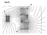
図14、図15及び図16において、単一の磁石12が案内部材2の遠位ヘッド内に図示されているが、単一の磁石12を磁石の配列に置換してもよいことは明白である。かかる磁石の配列の一例を図19に示し、図19は、案内部材のヘッド内に長手方向に配置された3つの中央の磁石43と、垂直方向に配置された2つの磁石44とを示している。これらの磁石は全て、磁石に対する軸線方向に磁化されている。単一の磁石が、3つの磁石から成る中央部分に置換されてもよいことが明らかである。この磁石形態は、ハルバッハ(Hallbach)配列に類似しているが、この場合、端部磁石の別の配向により、非対称な磁界が形成される。
In FIGS. 14, 15 and 16, a
図20は、この磁石の配列によって発生する磁界を概略的に示す。 FIG. 20 schematically shows the magnetic field generated by this magnet arrangement.
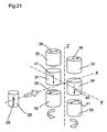
ここまで、図2〜図13の単一の永久磁石を参照して、案内部材のヘッド2の磁化部分を説明してきたけれども、磁化部分を特定の磁石の配列に置換してもよい。かかる配列を図21に概略的に示す。この図の左側において、切除先端部21内に配置された磁石が、y軸の原点からある距離のところに配置された円筒形磁石28として示されている。矢印29は、この磁石の磁化方向を表す。案内部材のヘッド2内に挿入されるように構成された磁石の配列を、図21の右側に示す。この磁石の配列は、3つの異なる永久磁石30、31、32、33、34、35の2つのグループで構成され、2つのグループは、z軸に対して対称に配置されている。磁石に対応する矢印36、37、38、39、40、41は、それぞれの磁化方向を示す。磁石28と磁石の配列30、31、32、33、34、35との間の磁力の大きさを制御するために、磁石30、31、32、33、34、35を同期回転させる。左列の磁石30、31、32を反時計方向に回転させる場合、右列の磁石33、34、35を同じ角度で時計方向に回転させなければならず、逆の場合も同様である。磁石の回転により、磁石28と案内部材のヘッド内の磁石の配列との間の引力は、ゼロまで減少させてもよいし、必要な場合、斥力に変えてもよい。力の大きさは、距離及び回転角度の両方に依存する。従って、かかる磁石の配列により、切除先端部14と食道内に配置された案内部材のヘッド2との間の引力を変化させることが可能である。図14に示す磁石の配列の位置は、磁石28に働く最大の力に対応する。回転する磁石の異なる形態を有する他の配列により、同じ結果を達成してもよいことは明白である。変形形態の一例を図22に示し、図22は、2つの直方体形状の磁石で囲まれた2つの円筒形磁石46からなる磁石の配列を示す。
So far, the magnetized portion of the
力/圧力センサと調整可能な磁力との組合せにより、臨床医は、案内部材と切除先端部の間の引力を正確に適合させることができる。 The combination of force / pressure sensor and adjustable magnetic force allows the clinician to accurately adapt the attractive force between the guide member and the cutting tip.
切除先端部14と案内部材のヘッド2との磁気的結合により、切除電極の位置が決定され、切除する組織に対して常に垂直であり、従って、連続的な切除線を達成することができる。温度センサが、切除電極を支持しない部材のヘッド2内に配置されていれば、臨床医は、切除領域の近傍における生理学的状態の正確な知識を有し、従って、切除電極に送るエネルギーを、治療中の食道壁の焼損を防止するように調整し且つ最適化することができる。
Due to the magnetic coupling between the cutting
ここで、この医療装置の作動原理を簡潔に説明する。この装置の主目的は、切除部材の先端部14内に配置された切除電極に送るエネルギーによって、連続的な切除線を左心房壁上に形成することにある。いったん心臓マッピングを実行して、心房内の処置すべき切除線又は領域を正確に決定したら、切除カテーテルを生来の通路、通常は鼠径部又は頸部領域内の静脈又は動脈の中を通して導入すると共に、医師による操縦機構の適切な操作によって、選択された心腔内に案内する。いったん、切除カテーテルを心房内の適所に配置したら、案内部材、即ち、食道カテーテルのヘッド2が左心房の近傍に達するまで、案内部材を患者の口又は鼻を通して食道内に導入する。同じ結果を達成するために、他の導入部位も可能であることに注目すべきである。
Here, the operating principle of this medical device will be briefly described. The main purpose of this device is to form a continuous ablation line on the left atrial wall with the energy delivered to the ablation electrode located in the
いったん食道カテーテルのヘッド2を上記位置に到達させると、食道カテーテルのヘッド2は、切除カテーテルの先端部14と磁気的に結合される。先端部14とヘッド2の磁気的結合は、食道壁と左心房壁の両方を介して起きる。いったんヘッド2と切除先端部14を結合させたら、食道カテーテルを引いたり押したりして、並びに、食道カテーテルヘッド2の遠位端部の曲げを生じさせるコマンドボタン5、6を操作して、食道カテーテルだけを長手方向並びに横方向の両方に移動させることによって、切除カテーテル先端部14を制御して案内するのがよい。従って、切除電極を支持する部材の操縦機構を操作する必要なしに、食道カテーテルだけを作動させることによって、切除カテーテルの切除先端部を左心房腔内で移動させることができる。食道カテーテルを移動させることにより、磁気的に結合された切除先端部14を引き、それにより、左心房の内面に沿った切除先端部の制御された移動を可能にする。臨床医が2つのカテーテルを正しく位置決めし且つヘッド2と切除先端部14の磁気的結合を可能にするために、一般的には、上記ステップを蛍光透視法又は医者を支援する任意の他の適切な非侵襲的画像形成法の下で実施する。いったんカテーテルを適所に配置し、磁気的に結合させたら、切除線の軌道を定め、無線周波数エネルギーを切除先端部に加えることなしに、第1の移動操作を行う。食道カテーテルを引張ったり押したりすることによって、システムの長手方向の移動を、左心房を横切るように実施する。長手方向移動の大きさを、食道カテーテルの近位端部の部分の上に現れるマーカーを参照して測定する。垂直方向の移動を、案内部材の操縦機構を作動させることによって得られる食道カテーテルの横方向の曲げによって達成する。図12及び図13に示す回転するボール又は光ファイバで送られる信号によって、切除先端部14の移動を正確に監視し且つ計算するのがよい。
Once the
引続いて、システムを3〜4ミリメートルごとに停止させる第2の操作を行い、エネルギーを切除電極に発生器によって加え、直径約4ミリメートルの損傷を形成する。これにより、決められた軌道全体に沿って連続する切除線を形成する。 Subsequently, a second operation is performed to stop the system every 3 to 4 millimeters, and energy is applied to the ablation electrode by a generator to create a damage of about 4 millimeters in diameter. This forms a continuous ablation line along the entire defined trajectory.
変形例として、切除先端部14は、当該技術で既知の他の切除手段、例えば、レーザ切除、極低温切除、超音波切除、マイクロ波切除の手段を有していてもよい。
Alternatively, the
当該技術において既知の位置センサを、切除カテーテルの先端部14及び/又は案内部材のヘッド2に一体化して、両カテーテルの3次元位置座標を直接得ることが有利である。
Advantageously, position sensors known in the art are integrated into the
簡略化された実施形態では、医療装置の2つの部材のうちの1つのみが、その遠位端部を移動させる手段を有していてもよい。例えば、切除先端部を支持する部材が、簡単な可撓性チューブで構成され、この可撓性チューブが、切除電極及び磁石を備えた遠位端部を有していてもよい。この部材を、例えば、案内カテーテルを用いて、心臓の上腔内に導入し、カテーテルのシースの中を通して押す。変形例として、温度センサを支持する部材も、単一の可撓性本体で構成され、この可撓性本体が、その遠位端部に、磁石と温度センサを備えたヘッドを有していてもよい。この場合、切除電極を支持する部材と磁気的に結合させた後、切除部材の案内を、前の段落で説明したように、カテーテル治療において用いられる従来の手段によって実現する。 In a simplified embodiment, only one of the two members of the medical device may have means for moving its distal end. For example, the member that supports the ablation tip may be a simple flexible tube, which may have a distal end with an ablation electrode and a magnet. This member is introduced into the upper chamber of the heart, for example using a guide catheter, and pushed through the sheath of the catheter. As a variant, the member supporting the temperature sensor is also composed of a single flexible body, which has a head with a magnet and a temperature sensor at its distal end. Also good. In this case, after being magnetically coupled to the member supporting the ablation electrode, guidance of the ablation member is achieved by conventional means used in catheter therapy, as described in the previous paragraph.
本発明の技術を左心房の治療に関連して説明したけれども、実際には、同じ原理を、心房中隔等の心臓の他の領域の切除に適用してもよいことは明白である。その場合、温度センサを支持するカテーテルを右心房内に配置し、切除カテーテルを左心房内に配置する。心房の下側後部を切除する場合、温度センサを支持する部材を冠状静脈洞内に配置し、切除カテーテルを左心房又は右心房の内に配置する。左心室を切除する場合、温度センサを支持する部材を冠状静脈内に配置し、切除カテーテルを左心室内に配置する。他の箇所も可能である。作動原理は同一のままであり、部材の寸法及び形態のみを、人体の上述の領域内に導入するように適合させるべきである。 Although the technique of the present invention has been described in connection with the treatment of the left atrium, it is clear that in practice the same principles may be applied to resection of other areas of the heart, such as the atrial septum. In that case, a catheter supporting the temperature sensor is placed in the right atrium and an ablation catheter is placed in the left atrium. When resecting the lower posterior portion of the atrium, a member supporting the temperature sensor is placed in the coronary sinus and an ablation catheter is placed in the left or right atrium. When ablating the left ventricle, a member that supports the temperature sensor is placed in the coronary vein and an ablation catheter is placed in the left ventricle. Other locations are possible. The principle of operation remains the same and only the dimensions and form of the member should be adapted to be introduced into the above-mentioned region of the human body.
本発明の医療装置及び方法により、切除先端部の上での完全な制御を達成し、治療すべき領域内における正確な連続切除線の生成を可能にし、それと同時に、治療すべき領域の近傍における組織の温度の正確な測定により、治療すべき領域への熱傷の危険を最小にする。 The medical device and method of the present invention achieves complete control over the ablation tip and allows the generation of an accurate continuous ablation line within the area to be treated while at the same time in the vicinity of the area to be treated. Accurate measurement of tissue temperature minimizes the risk of burns to the area to be treated.
本発明を、特定の実施形態を参照して説明したが、上記説明は、本発明の例示であり、本発明を限定するものと解釈すべきではない。当業者であれば、特許請求の範囲に記載された本発明の真の精神及び範囲から逸脱することなしに、種々の変更例及び適用例に思い至るであろう。 Although the present invention has been described with reference to particular embodiments, the above description is illustrative of the invention and is not to be construed as limiting the invention. Those skilled in the art will envision various modifications and applications without departing from the true spirit and scope of the invention as set forth in the claims.
Claims (16)
人体の第1の領域内の生来の通路によって導入されるように構成された案内部材を有し、前記案内部材は、ヘッド(2)を含む遠位端部を有し、前記ヘッドは、少なくとも1つの磁石(12)と温度センサ(20)とを有し、
更に、心腔に導入されるように構成された切除部材を有し、前記切除部材は、遠位先端部(14)を有し、前記遠位先端部は、少なくとも1つの切除手段と少なくとも1つの磁石(15)とを有し、前記切除部材の少なくとも1つの磁石は、前記案内部材の少なくとも1つの磁石(12)と人体組織を介して磁気的に結合し且つ相互作用することが可能である、医療装置。 A medical device for performing tissue resection in a heart chamber,
A guide member configured to be introduced by a natural passage in a first region of the human body, the guide member having a distal end including a head (2), the head comprising at least One magnet (12) and a temperature sensor (20);
And a cutting member configured to be introduced into the heart chamber, the cutting member having a distal tip (14), the distal tip having at least one cutting means and at least one cutting tool. And at least one magnet of the cutting member is capable of magnetically coupling and interacting with at least one magnet (12) of the guide member via human tissue. A medical device.
カテーテルの遠位端部に取付けられた切除部材の先端部(14)を心腔内に挿入して配置する工程と、
案内部材の遠位ヘッド(2)を患者の食道、又は、治療すべき心腔の近傍の他の箇所の中に挿入する工程と、
前記案内部材のヘッド(2)及び前記切除部材の先端部(14)を磁気的に結合させる工程と、
前記案内部材のヘッド(2)だけを移動させることによって、前記切除先端部(14)を予め決められた軌道に沿って案内する工程と、
前記切除部材の先端部(14)にエネルギーを加えて、心臓組織の切除を行う工程と、を有する方法。 A method for guiding a distal end (14) of a resection member during resection of heart tissue in a heart chamber, comprising:
Inserting and placing the tip (14) of the resection member attached to the distal end of the catheter into the heart chamber;
Inserting the distal head (2) of the guide member into the patient's esophagus or other location near the heart chamber to be treated;
Magnetically coupling the head (2) of the guide member and the tip (14) of the cutting member;
Guiding the cutting tip (14) along a predetermined trajectory by moving only the head (2) of the guide member;
Cutting the heart tissue by applying energy to the tip (14) of the cutting member.
Applications Claiming Priority (2)
| Application Number | Priority Date | Filing Date | Title |
|---|---|---|---|
| IB2006001917 | 2006-07-12 | ||
| PCT/IB2007/001869 WO2008010039A2 (en) | 2006-07-12 | 2007-07-06 | Medical device for tissue ablation |
Publications (2)
| Publication Number | Publication Date |
|---|---|
| JP2009545338A true JP2009545338A (en) | 2009-12-24 |
| JP2009545338A5 JP2009545338A5 (en) | 2010-08-12 |
Family
ID=38458289
Family Applications (1)
| Application Number | Title | Priority Date | Filing Date |
|---|---|---|---|
| JP2009518993A Pending JP2009545338A (en) | 2006-07-12 | 2007-07-06 | Medical device for tissue resection |
Country Status (4)
| Country | Link |
|---|---|
| US (1) | US8048072B2 (en) |
| EP (1) | EP2037828A2 (en) |
| JP (1) | JP2009545338A (en) |
| WO (1) | WO2008010039A2 (en) |
Cited By (4)
| Publication number | Priority date | Publication date | Assignee | Title |
|---|---|---|---|---|
| JP2011505193A (en) * | 2007-11-30 | 2011-02-24 | セント・ジュード・メディカル・エイトリアル・フィブリレーション・ディヴィジョン・インコーポレーテッド | Perfusion ablation catheter with magnetic tip for magnetic field control and guidance |
| JP2019503229A (en) * | 2016-01-15 | 2019-02-07 | ティーブイエー メディカル, インコーポレイテッド | System and method for adhering vessels |
| JP2019030758A (en) * | 2013-03-14 | 2019-02-28 | ティーブイエー メディカル, インコーポレイテッド | Fistula formulation devices and methods therefor |
| US10499985B2 (en) | 2006-05-16 | 2019-12-10 | St. Jude Medical, Atrial Fibrillation Division, Inc. | Ablation electrode assembly and methods for improved control of temperature and minimization of coagulation and tissue damage |
Families Citing this family (103)
| Publication number | Priority date | Publication date | Assignee | Title |
|---|---|---|---|---|
| US11478152B2 (en) | 2005-02-02 | 2022-10-25 | Intuitive Surgical Operations, Inc. | Electrophysiology mapping and visualization system |
| US20080015569A1 (en) | 2005-02-02 | 2008-01-17 | Voyage Medical, Inc. | Methods and apparatus for treatment of atrial fibrillation |
| US8050746B2 (en) * | 2005-02-02 | 2011-11-01 | Voyage Medical, Inc. | Tissue visualization device and method variations |
| US7930016B1 (en) | 2005-02-02 | 2011-04-19 | Voyage Medical, Inc. | Tissue closure system |
| US10064540B2 (en) * | 2005-02-02 | 2018-09-04 | Intuitive Surgical Operations, Inc. | Visualization apparatus for transseptal access |
| US8137333B2 (en) | 2005-10-25 | 2012-03-20 | Voyage Medical, Inc. | Delivery of biological compounds to ischemic and/or infarcted tissue |
| US9510732B2 (en) * | 2005-10-25 | 2016-12-06 | Intuitive Surgical Operations, Inc. | Methods and apparatus for efficient purging |
| US7860556B2 (en) * | 2005-02-02 | 2010-12-28 | Voyage Medical, Inc. | Tissue imaging and extraction systems |
| US7918787B2 (en) | 2005-02-02 | 2011-04-05 | Voyage Medical, Inc. | Tissue visualization and manipulation systems |
| US7860555B2 (en) * | 2005-02-02 | 2010-12-28 | Voyage Medical, Inc. | Tissue visualization and manipulation system |
| US8078266B2 (en) | 2005-10-25 | 2011-12-13 | Voyage Medical, Inc. | Flow reduction hood systems |
| US8221310B2 (en) | 2005-10-25 | 2012-07-17 | Voyage Medical, Inc. | Tissue visualization device and method variations |
| US9055906B2 (en) | 2006-06-14 | 2015-06-16 | Intuitive Surgical Operations, Inc. | In-vivo visualization systems |
| US20080033241A1 (en) * | 2006-08-01 | 2008-02-07 | Ruey-Feng Peh | Left atrial appendage closure |
| US20080097476A1 (en) | 2006-09-01 | 2008-04-24 | Voyage Medical, Inc. | Precision control systems for tissue visualization and manipulation assemblies |
| WO2008028149A2 (en) | 2006-09-01 | 2008-03-06 | Voyage Medical, Inc. | Electrophysiology mapping and visualization system |
| US10004388B2 (en) | 2006-09-01 | 2018-06-26 | Intuitive Surgical Operations, Inc. | Coronary sinus cannulation |
| US10335131B2 (en) | 2006-10-23 | 2019-07-02 | Intuitive Surgical Operations, Inc. | Methods for preventing tissue migration |
| US20080183036A1 (en) | 2006-12-18 | 2008-07-31 | Voyage Medical, Inc. | Systems and methods for unobstructed visualization and ablation |
| US8758229B2 (en) | 2006-12-21 | 2014-06-24 | Intuitive Surgical Operations, Inc. | Axial visualization systems |
| US8131350B2 (en) * | 2006-12-21 | 2012-03-06 | Voyage Medical, Inc. | Stabilization of visualization catheters |
| US8366707B2 (en) * | 2007-01-23 | 2013-02-05 | Cvdevices Llc | Systems and methods for epicardial navigation |
| WO2008112870A2 (en) | 2007-03-13 | 2008-09-18 | University Of Virginia Patent Foundation | Epicardial ablation catheter and method of use |
| US9211405B2 (en) * | 2007-03-22 | 2015-12-15 | University Of Virginia Patent Foundation | Electrode catheter for ablation purposes and related method thereof |
| US8979837B2 (en) | 2007-04-04 | 2015-03-17 | St. Jude Medical, Atrial Fibrillation Division, Inc. | Flexible tip catheter with extended fluid lumen |
| US8187267B2 (en) * | 2007-05-23 | 2012-05-29 | St. Jude Medical, Atrial Fibrillation Division, Inc. | Ablation catheter with flexible tip and methods of making the same |
| US8764742B2 (en) | 2007-04-04 | 2014-07-01 | St. Jude Medical, Atrial Fibrillation Division, Inc. | Irrigated catheter |
| US8517999B2 (en) | 2007-04-04 | 2013-08-27 | St. Jude Medical, Atrial Fibrillation Division, Inc. | Irrigated catheter with improved fluid flow |
| WO2008134457A1 (en) * | 2007-04-27 | 2008-11-06 | Voyage Medical, Inc. | Complex shape steerable tissue visualization and manipulation catheter |
| US8657805B2 (en) | 2007-05-08 | 2014-02-25 | Intuitive Surgical Operations, Inc. | Complex shape steerable tissue visualization and manipulation catheter |
| US8709008B2 (en) * | 2007-05-11 | 2014-04-29 | Intuitive Surgical Operations, Inc. | Visual electrode ablation systems |
| US8974454B2 (en) | 2009-12-31 | 2015-03-10 | St. Jude Medical, Atrial Fibrillation Division, Inc. | Kit for non-invasive electrophysiology procedures and method of its use |
| US8734440B2 (en) * | 2007-07-03 | 2014-05-27 | St. Jude Medical, Atrial Fibrillation Division, Inc. | Magnetically guided catheter |
| EP2166936A4 (en) | 2007-07-03 | 2010-07-28 | Irvine Biomedical Inc | Magnetically guided catheter with flexible tip |
| US20090030276A1 (en) * | 2007-07-27 | 2009-01-29 | Voyage Medical, Inc. | Tissue visualization catheter with imaging systems integration |
| US20090062790A1 (en) * | 2007-08-31 | 2009-03-05 | Voyage Medical, Inc. | Direct visualization bipolar ablation systems |
| US8235985B2 (en) * | 2007-08-31 | 2012-08-07 | Voyage Medical, Inc. | Visualization and ablation system variations |
| US20100241185A1 (en) | 2007-11-09 | 2010-09-23 | University Of Virginia Patent Foundation | Steerable epicardial pacing catheter system placed via the subxiphoid process |
| US8100899B2 (en) * | 2007-11-12 | 2012-01-24 | Ihc Intellectual Asset Management, Llc | Combined endocardial and epicardial magnetically coupled ablation device |
| US20090125022A1 (en) * | 2007-11-12 | 2009-05-14 | Voyage Medical, Inc. | Tissue visualization and ablation systems |
| US8641710B2 (en) | 2007-11-12 | 2014-02-04 | Intermountain Invention Management, Llc | Magnetically coupling devices for mapping and/or ablating |
| US20090143640A1 (en) * | 2007-11-26 | 2009-06-04 | Voyage Medical, Inc. | Combination imaging and treatment assemblies |
| US8858609B2 (en) | 2008-02-07 | 2014-10-14 | Intuitive Surgical Operations, Inc. | Stent delivery under direct visualization |
| US20090326572A1 (en) * | 2008-06-27 | 2009-12-31 | Ruey-Feng Peh | Apparatus and methods for rapid tissue crossing |
| US9101735B2 (en) * | 2008-07-07 | 2015-08-11 | Intuitive Surgical Operations, Inc. | Catheter control systems |
| US20110288544A1 (en) * | 2008-07-17 | 2011-11-24 | Maestroheart Sa | Medical device for tissue ablation |
| US8894643B2 (en) | 2008-10-10 | 2014-11-25 | Intuitive Surgical Operations, Inc. | Integral electrode placement and connection systems |
| US8333012B2 (en) | 2008-10-10 | 2012-12-18 | Voyage Medical, Inc. | Method of forming electrode placement and connection systems |
| US9468364B2 (en) * | 2008-11-14 | 2016-10-18 | Intuitive Surgical Operations, Inc. | Intravascular catheter with hood and image processing systems |
| KR101164887B1 (en) * | 2009-03-19 | 2012-07-19 | 서울대학교병원 | Bipolar Radiofrequency Ablation Catheter |
| US20100256629A1 (en) * | 2009-04-06 | 2010-10-07 | Voyage Medical, Inc. | Methods and devices for treatment of the ostium |
| US8430875B2 (en) | 2009-05-19 | 2013-04-30 | Estech, Inc. (Endoscopic Technologies, Inc.) | Magnetic navigation systems and methods |
| US9642534B2 (en) | 2009-09-11 | 2017-05-09 | University Of Virginia Patent Foundation | Systems and methods for determining location of an access needle in a subject |
| US20110087224A1 (en) * | 2009-10-09 | 2011-04-14 | Cadeddu Jeffrey A | Magnetic surgical sled with variable arm |
| US8882762B2 (en) * | 2009-11-30 | 2014-11-11 | The Board Of Trustees Of The Leland Stanford Junior University | Transmural ablation device |
| US8694071B2 (en) | 2010-02-12 | 2014-04-08 | Intuitive Surgical Operations, Inc. | Image stabilization techniques and methods |
| DE102010010478A1 (en) * | 2010-03-06 | 2011-09-08 | Peter Osypka | Device for ablating the mouth of a pulmonary vein |
| US9814522B2 (en) | 2010-04-06 | 2017-11-14 | Intuitive Surgical Operations, Inc. | Apparatus and methods for ablation efficacy |
| AU2011328926B2 (en) | 2010-11-16 | 2015-07-09 | Tva Medical, Inc. | Devices and methods for forming a fistula |
| US9332990B2 (en) * | 2010-12-30 | 2016-05-10 | Wake Forest University Health Sciences | Ureter to ileal conduit anastomosis using magnetic compression and related delivery devices and methods |
| US20120197061A1 (en) * | 2010-12-30 | 2012-08-02 | Jay Anthony Requarth | Magnetic compression delivery devices and related devices and methods |
| WO2013008204A2 (en) | 2011-07-12 | 2013-01-17 | Maestroheart Sa | System for tissue marking and treatment |
| EP2796103B1 (en) | 2011-08-25 | 2017-02-22 | Covidien LP | Systems and devices for treatment of luminal tissue |
| US9131245B2 (en) | 2011-09-23 | 2015-09-08 | Qualcomm Incorporated | Reference picture list construction for video coding |
| US10456196B2 (en) | 2011-12-15 | 2019-10-29 | Biosense Webster (Israel) Ltd. | Monitoring and tracking bipolar ablation |
| CN107835428B (en) * | 2012-03-02 | 2021-09-24 | 太阳专利托管公司 | Image encoding method, image decoding method, image encoding device, image decoding device, and image encoding/decoding device |
| JP6301926B2 (en) | 2012-08-09 | 2018-03-28 | ユニバーシティ オブ アイオワ リサーチ ファウンデーション | Catheter, catheter system, and method for piercing tissue structure |
| US20150196752A1 (en) * | 2012-08-10 | 2015-07-16 | Intermountain Invention Managment, Llc | Epicardial lead placement apparatus, systems, and methods |
| WO2014059351A1 (en) | 2012-10-11 | 2014-04-17 | Tva Medical, Inc. | Devices and methods for fistula formation |
| CA2897740C (en) | 2013-01-14 | 2022-01-04 | Corpak Medsystems, Inc. | Bridle delivery system, method, and apparatus for securing nasal tubes |
| WO2015040557A1 (en) * | 2013-09-17 | 2015-03-26 | Krishnan Subramaniam C | Dual catheter ablation system |
| EP3091921B1 (en) | 2014-01-06 | 2019-06-19 | Farapulse, Inc. | Apparatus for renal denervation ablation |
| WO2015138998A1 (en) | 2014-03-14 | 2015-09-17 | Tva Medical, Inc. | Fistula formation devices and methods therefor |
| WO2015171921A2 (en) | 2014-05-07 | 2015-11-12 | Mickelson Steven R | Methods and apparatus for selective tissue ablation |
| EP3154463B1 (en) | 2014-06-12 | 2019-03-27 | Farapulse, Inc. | Apparatus for rapid and selective transurethral tissue ablation |
| WO2015192018A1 (en) | 2014-06-12 | 2015-12-17 | Iowa Approach Inc. | Method and apparatus for rapid and selective tissue ablation with cooling |
| US9743972B2 (en) * | 2014-07-18 | 2017-08-29 | Medtronic Cryocath Lp | Cardiac cryolipolysis for the treatment of cardiac arrhythmia |
| US10646666B2 (en) | 2014-08-27 | 2020-05-12 | Tva Medical, Inc. | Cryolipolysis devices and methods therefor |
| WO2016060983A1 (en) | 2014-10-14 | 2016-04-21 | Iowa Approach Inc. | Method and apparatus for rapid and safe pulmonary vein cardiac ablation |
| US10603040B1 (en) | 2015-02-09 | 2020-03-31 | Tva Medical, Inc. | Methods for treating hypertension and reducing blood pressure with formation of fistula |
| US10172673B2 (en) | 2016-01-05 | 2019-01-08 | Farapulse, Inc. | Systems devices, and methods for delivery of pulsed electric field ablative energy to endocardial tissue |
| US20170189097A1 (en) | 2016-01-05 | 2017-07-06 | Iowa Approach Inc. | Systems, apparatuses and methods for delivery of ablative energy to tissue |
| US10660702B2 (en) | 2016-01-05 | 2020-05-26 | Farapulse, Inc. | Systems, devices, and methods for focal ablation |
| US10130423B1 (en) | 2017-07-06 | 2018-11-20 | Farapulse, Inc. | Systems, devices, and methods for focal ablation |
| US10512505B2 (en) | 2018-05-07 | 2019-12-24 | Farapulse, Inc. | Systems, apparatuses and methods for delivery of ablative energy to tissue |
| US11026743B2 (en) | 2016-01-15 | 2021-06-08 | Tva Medical, Inc. | Devices and methods for forming a fistula |
| EP4299099A3 (en) | 2016-01-15 | 2024-04-03 | TVA Medical, Inc. | Devices for advancing a wire |
| US10874422B2 (en) | 2016-01-15 | 2020-12-29 | Tva Medical, Inc. | Systems and methods for increasing blood flow |
| WO2017218734A1 (en) | 2016-06-16 | 2017-12-21 | Iowa Approach, Inc. | Systems, apparatuses, and methods for guide wire delivery |
| MX2019003251A (en) | 2016-09-25 | 2019-07-18 | Tva Medical Inc | Vascular stent devices and methods. |
| US9987081B1 (en) | 2017-04-27 | 2018-06-05 | Iowa Approach, Inc. | Systems, devices, and methods for signal generation |
| US10617867B2 (en) | 2017-04-28 | 2020-04-14 | Farapulse, Inc. | Systems, devices, and methods for delivery of pulsed electric field ablative energy to esophageal tissue |
| EP3681391A1 (en) | 2017-09-12 | 2020-07-22 | Farapulse, Inc. | Systems, apparatuses, and methods for ventricular focal ablation |
| CN116327352A (en) | 2018-05-07 | 2023-06-27 | 波士顿科学医学有限公司 | Epicardial ablation catheter |
| WO2019217317A1 (en) | 2018-05-07 | 2019-11-14 | Farapulse, Inc. | Systems, apparatuses, and methods for filtering high voltage noise induced by pulsed electric field ablation |
| JP2022501112A (en) | 2018-09-20 | 2022-01-06 | ファラパルス,インコーポレイテッド | Systems, devices, and methods for the delivery of pulsed field ablation energy to endocardial tissue |
| US10625080B1 (en) | 2019-09-17 | 2020-04-21 | Farapulse, Inc. | Systems, apparatuses, and methods for detecting ectopic electrocardiogram signals during pulsed electric field ablation |
| WO2021087486A1 (en) * | 2019-11-01 | 2021-05-06 | The Board Of Trustees Of The Leland Stanford Junior University | Devices and methods involving transmural-capable tissue procedures |
| US11065047B2 (en) | 2019-11-20 | 2021-07-20 | Farapulse, Inc. | Systems, apparatuses, and methods for protecting electronic components from high power noise induced by high voltage pulses |
| US11497541B2 (en) | 2019-11-20 | 2022-11-15 | Boston Scientific Scimed, Inc. | Systems, apparatuses, and methods for protecting electronic components from high power noise induced by high voltage pulses |
| US10842572B1 (en) | 2019-11-25 | 2020-11-24 | Farapulse, Inc. | Methods, systems, and apparatuses for tracking ablation devices and generating lesion lines |
| JP7350684B2 (en) * | 2020-03-25 | 2023-09-26 | 株式会社メディカロイド | electrosurgical instruments |
| WO2023129842A2 (en) * | 2021-12-28 | 2023-07-06 | Atricure, Inc. | Magnetically coupled ablation components |
Citations (3)
| Publication number | Priority date | Publication date | Assignee | Title |
|---|---|---|---|---|
| JPH08502905A (en) * | 1992-09-01 | 1996-04-02 | エドウィン エル アデアー, | Sterilizable endoscope with detachable disposable tube assembly |
| JPH0889582A (en) * | 1994-09-28 | 1996-04-09 | Fuji Syst Kk | Catheter for medical treatment and its guiding method |
| US20060106375A1 (en) * | 2004-11-15 | 2006-05-18 | Werneth Randell L | Ablation system with feedback |
Family Cites Families (8)
| Publication number | Priority date | Publication date | Assignee | Title |
|---|---|---|---|---|
| US5429131A (en) * | 1994-02-25 | 1995-07-04 | The Regents Of The University Of California | Magnetized electrode tip catheter |
| US6292678B1 (en) | 1999-05-13 | 2001-09-18 | Stereotaxis, Inc. | Method of magnetically navigating medical devices with magnetic fields and gradients, and medical devices adapted therefor |
| CA2377583A1 (en) * | 1999-07-19 | 2001-01-25 | Epicor, Inc. | Apparatus and method for ablating tissue |
| US6807968B2 (en) * | 2001-04-26 | 2004-10-26 | Medtronic, Inc. | Method and system for treatment of atrial tachyarrhythmias |
| JP4091004B2 (en) | 2003-02-04 | 2008-05-28 | オリンパス株式会社 | Medical device guidance system |
| US7166127B2 (en) * | 2003-12-23 | 2007-01-23 | Mitralign, Inc. | Tissue fastening systems and methods utilizing magnetic guidance |
| US20050187545A1 (en) * | 2004-02-20 | 2005-08-25 | Hooven Michael D. | Magnetic catheter ablation device and method |
| US20060069385A1 (en) * | 2004-09-28 | 2006-03-30 | Scimed Life Systems, Inc. | Methods and apparatus for tissue cryotherapy |
-
2007
- 2007-07-06 US US12/373,281 patent/US8048072B2/en not_active Expired - Fee Related
- 2007-07-06 JP JP2009518993A patent/JP2009545338A/en active Pending
- 2007-07-06 EP EP07804572A patent/EP2037828A2/en not_active Withdrawn
- 2007-07-06 WO PCT/IB2007/001869 patent/WO2008010039A2/en active Application Filing
Patent Citations (3)
| Publication number | Priority date | Publication date | Assignee | Title |
|---|---|---|---|---|
| JPH08502905A (en) * | 1992-09-01 | 1996-04-02 | エドウィン エル アデアー, | Sterilizable endoscope with detachable disposable tube assembly |
| JPH0889582A (en) * | 1994-09-28 | 1996-04-09 | Fuji Syst Kk | Catheter for medical treatment and its guiding method |
| US20060106375A1 (en) * | 2004-11-15 | 2006-05-18 | Werneth Randell L | Ablation system with feedback |
Cited By (7)
| Publication number | Priority date | Publication date | Assignee | Title |
|---|---|---|---|---|
| US10499985B2 (en) | 2006-05-16 | 2019-12-10 | St. Jude Medical, Atrial Fibrillation Division, Inc. | Ablation electrode assembly and methods for improved control of temperature and minimization of coagulation and tissue damage |
| US11478300B2 (en) | 2006-05-16 | 2022-10-25 | St. Jude Medical, Atrial Fibrillation Division, Inc. | Ablation electrode assembly and methods for improved control of temperature and minimization of coagulation and tissue damage |
| JP2011505193A (en) * | 2007-11-30 | 2011-02-24 | セント・ジュード・メディカル・エイトリアル・フィブリレーション・ディヴィジョン・インコーポレーテッド | Perfusion ablation catheter with magnetic tip for magnetic field control and guidance |
| JP2019030758A (en) * | 2013-03-14 | 2019-02-28 | ティーブイエー メディカル, インコーポレイテッド | Fistula formulation devices and methods therefor |
| JP2019503229A (en) * | 2016-01-15 | 2019-02-07 | ティーブイエー メディカル, インコーポレイテッド | System and method for adhering vessels |
| JP2022000187A (en) * | 2016-01-15 | 2022-01-04 | ティーブイエー メディカル, インコーポレイテッド | Systems and methods for adhering vessels |
| JP7219090B2 (en) | 2016-01-15 | 2023-02-07 | ティーブイエー メディカル, インコーポレイテッド | Systems and methods for gluing vessels |
Also Published As
| Publication number | Publication date |
|---|---|
| US8048072B2 (en) | 2011-11-01 |
| WO2008010039A2 (en) | 2008-01-24 |
| WO2008010039A3 (en) | 2008-04-17 |
| US20100004661A1 (en) | 2010-01-07 |
| EP2037828A2 (en) | 2009-03-25 |
Similar Documents
| Publication | Publication Date | Title |
|---|---|---|
| JP2009545338A (en) | Medical device for tissue resection | |
| US11839424B2 (en) | Monitoring, managing and/or protecting system and method for non-targeted tissue | |
| JP6333545B2 (en) | Lasso catheter with tip electrode | |
| EP2887988B1 (en) | Catheter having reduced force concentration at tissue contact site | |
| US20110288544A1 (en) | Medical device for tissue ablation | |
| JP5788205B2 (en) | Dual purpose lasso catheter with irrigation using ring-bump electrodes arranged in a ring | |
| US6238390B1 (en) | Ablation catheter system having linear lesion capabilities | |
| US8784414B2 (en) | Preshaped localization catheter, system, and method for graphically reconstructing pulmonary vein ostia | |
| RU2526964C2 (en) | Dual-purpose lasso catheter with irrigation | |
| EP1832307B1 (en) | Esophagus isolation device | |
| US6663622B1 (en) | Surgical devices and methods for use in tissue ablation procedures | |
| US20080004595A1 (en) | Electrostriction Devices and Methods for Assisted Magnetic Navigation | |
| US20050187545A1 (en) | Magnetic catheter ablation device and method | |
| US20200060569A1 (en) | Curved high density electrode mapping catheter | |
| JP2002531165A (en) | Internal mechanism for moving slidable electrodes | |
| WO2008045929A2 (en) | Ablation electrode and catheter system | |
| JP2011120912A (en) | Pre-formed curved ablation catheter | |
| JP2005052641A (en) | Apparatus for pulmonary vein mapping and ablation | |
| JP6890946B2 (en) | Lasso catheter with movable ablation needle | |
| WO2011101778A1 (en) | Ablation catheter and a method of performing ablation | |
| CN112584737A (en) | Device and accessory for percutaneous endoscopic access and ablation system | |
| US20160120614A1 (en) | Displacement control wire device and method | |
| JP2024500569A (en) | Multi-needle ablation probe |
Legal Events
| Date | Code | Title | Description |
|---|---|---|---|
| A521 | Written amendment |
Free format text: JAPANESE INTERMEDIATE CODE: A523 Effective date: 20100622 |
|
| A621 | Written request for application examination |
Free format text: JAPANESE INTERMEDIATE CODE: A621 Effective date: 20100622 |
|
| A977 | Report on retrieval |
Free format text: JAPANESE INTERMEDIATE CODE: A971007 Effective date: 20120517 |
|
| A131 | Notification of reasons for refusal |
Free format text: JAPANESE INTERMEDIATE CODE: A131 Effective date: 20120528 |
|
| A601 | Written request for extension of time |
Free format text: JAPANESE INTERMEDIATE CODE: A601 Effective date: 20120827 |
|
| A602 | Written permission of extension of time |
Free format text: JAPANESE INTERMEDIATE CODE: A602 Effective date: 20120903 |
|
| A02 | Decision of refusal |
Free format text: JAPANESE INTERMEDIATE CODE: A02 Effective date: 20130304 |