JP2009542422A - Medical device with expansion mechanism - Google Patents
Medical device with expansion mechanism Download PDFInfo
- Publication number
- JP2009542422A JP2009542422A JP2009519610A JP2009519610A JP2009542422A JP 2009542422 A JP2009542422 A JP 2009542422A JP 2009519610 A JP2009519610 A JP 2009519610A JP 2009519610 A JP2009519610 A JP 2009519610A JP 2009542422 A JP2009542422 A JP 2009542422A
- Authority
- JP
- Japan
- Prior art keywords
- elongate body
- distal end
- lumen
- elongate
- sheath
- Prior art date
- Legal status (The legal status is an assumption and is not a legal conclusion. Google has not performed a legal analysis and makes no representation as to the accuracy of the status listed.)
- Pending
Links
Images


Classifications
-
- A—HUMAN NECESSITIES
- A61—MEDICAL OR VETERINARY SCIENCE; HYGIENE
- A61B—DIAGNOSIS; SURGERY; IDENTIFICATION
- A61B17/00—Surgical instruments, devices or methods, e.g. tourniquets
- A61B17/16—Bone cutting, breaking or removal means other than saws, e.g. Osteoclasts; Drills or chisels for bones; Trepans
- A61B17/1662—Bone cutting, breaking or removal means other than saws, e.g. Osteoclasts; Drills or chisels for bones; Trepans for particular parts of the body
- A61B17/1671—Bone cutting, breaking or removal means other than saws, e.g. Osteoclasts; Drills or chisels for bones; Trepans for particular parts of the body for the spine
-
- A—HUMAN NECESSITIES
- A61—MEDICAL OR VETERINARY SCIENCE; HYGIENE
- A61B—DIAGNOSIS; SURGERY; IDENTIFICATION
- A61B17/00—Surgical instruments, devices or methods, e.g. tourniquets
- A61B17/16—Bone cutting, breaking or removal means other than saws, e.g. Osteoclasts; Drills or chisels for bones; Trepans
- A61B17/1613—Component parts
- A61B17/1615—Drill bits, i.e. rotating tools extending from a handpiece to contact the worked material
- A61B17/1617—Drill bits, i.e. rotating tools extending from a handpiece to contact the worked material with mobile or detachable parts
-
- A—HUMAN NECESSITIES
- A61—MEDICAL OR VETERINARY SCIENCE; HYGIENE
- A61B—DIAGNOSIS; SURGERY; IDENTIFICATION
- A61B17/00—Surgical instruments, devices or methods, e.g. tourniquets
- A61B2017/00831—Material properties
- A61B2017/00867—Material properties shape memory effect
-
- A—HUMAN NECESSITIES
- A61—MEDICAL OR VETERINARY SCIENCE; HYGIENE
- A61B—DIAGNOSIS; SURGERY; IDENTIFICATION
- A61B2217/00—General characteristics of surgical instruments
- A61B2217/002—Auxiliary appliance
- A61B2217/005—Auxiliary appliance with suction drainage system
Abstract
【課題】組織にアクセスし、組織内部で装置を拡張させるための装置及び方法が本明細書で開示される。
【解決手段】一実施形態では、拡張可能部材が、拡張された構成にあって生体に対して回転されるときに、生体内の組織を破壊するように構成される。アクチュエータが、拡張可能部材に結合され、拡張可能部材を拡張された構成にバイアスするように構成される。アクチュエータが作動されるとき、アクチュエータが、拡張可能部材を縮退された構成に移動させるように構成される。生体は、例えば、椎骨または椎間板であってよい。いくつかの実施形態では、医療デバイスが、拡張可能部材を縮退された構成にバイアスし、作動時に、拡張可能部材を拡張された構成に移動させるように構成されたアクチュエータを含む。
【選択図】図22Disclosed herein are devices and methods for accessing an organization and expanding the device within the organization.
In one embodiment, an expandable member is configured to destroy tissue in a living body when in the expanded configuration and rotated relative to the living body. An actuator is coupled to the expandable member and is configured to bias the expandable member to an expanded configuration. When the actuator is actuated, the actuator is configured to move the expandable member to the retracted configuration. The living body may be, for example, a vertebra or an intervertebral disc. In some embodiments, the medical device includes an actuator configured to bias the expandable member to a collapsed configuration and to move the expandable member to the expanded configuration upon actuation.
[Selection] Figure 22
Description
(関連出願の相互参照)
本出願は、2006年7月7日出願の「Medical Device With Dual Expansion Mechanism」という名称の米国仮特許出願第60/818996号、2007年7月5日出願の「Medical Device With Dual Expansion Mechanism」という名称の米国特許出願第11/773871号、2007年7月5日出願の「Medical Device With Dual Expansion Mechanism」という名称の米国特許出願第11/773872号、及び2007年7月5日出願の「Medical Device With Dual Expansion Mechanism」という名称の米国特許出願第11/773876号に対する優先権を主張するものであり、それらの特許出願の開示の全体を、参照として本明細書に組み込む。
(Cross-reference of related applications)
This application is a US Provisional Patent Application No. 60/818996 filed July 7, 2006, entitled “Medical Device With Dual Expansion Mechanism”, and “Medical Device With Dual Expansion Mechanism” filed July 5, 2007. US patent application Ser. No. 11 / 773,871, entitled “Medical Device With Dual Expansion Mechanism”, filed Jul. 5, 2007, and “Medical,” filed Jul. 5, 2007; No. 11/773876 entitled “Device With Dual Expansion Mechanism” is claimed and the entire disclosure of those patent applications is incorporated herein by reference.
本発明は、一般に、例えば、組織に経皮的にアクセスし、二重拡張機構によってデバイスを拡張させるための医療デバイスを含む医療デバイス及び処置に関する。 The present invention generally relates to medical devices and procedures, including, for example, medical devices for percutaneously accessing tissue and expanding the device by a double expansion mechanism.
既知の医療デバイスは、様々な異なる医療処置を行うために、椎骨または脊椎の他の領域に経皮的にアクセスするように構成されている。いくつかの既知の医療デバイスは、椎骨または椎間板の内域の内部から組織を除去するように構成される。他の既知の医療デバイスは、椎骨または椎間板の内部の組織を断裂、破壊、及び/又は弛緩させるための何らかのタイプの切断手段を提供するように構成される。 Known medical devices are configured for percutaneous access to vertebrae or other areas of the spine to perform a variety of different medical procedures. Some known medical devices are configured to remove tissue from within the interior of the vertebra or intervertebral disc. Other known medical devices are configured to provide some type of cutting means for rupturing, destroying, and / or relaxing tissue within a vertebra or disc.
いくつかの医療処置では、医療デバイスが組織を切断する一方で、椎骨内部の組織など、破壊または切断された材料がデバイス内部に詰まることがあり、椎骨から引き出すためにデバイスを縮退するのを困難にする。 In some medical procedures, while the medical device cuts tissue, material that has been broken or cut, such as tissue inside the vertebra, can become clogged inside the device, making it difficult to degenerate the device for extraction from the vertebra To.
生体内部で拡張及び縮退させることができる、椎骨内部の組織など生体内部の組織を破壊するための装置及び方法が必要である。 What is needed is an apparatus and method for destroying tissue inside a living body, such as tissue inside a vertebra, that can be expanded and contracted inside the body.
組織にアクセスし、組織内部で装置を拡張させるための装置及び方法が、本明細書に開示される。一実施形態では、拡張可能部材は、拡張された構成にあって生体に対して回転されるときに、生体内の組織を破壊するように構成される。アクチュエータが、拡張可能部材に結合され、拡張可能部材を拡張された構成にバイアスするように構成される。アクチュエータが作動されるとき、アクチュエータは、拡張可能部材を縮退された構成に移動させるように構成される。生体は、例えば、椎骨または椎間板であってよい。いくつかの実施形態では、医療デバイスは、拡張可能部材を縮退された構成にバイアスし、作動時に、拡張可能部材を拡張された構成に移動させるように構成されたアクチュエータを含む。 Disclosed herein are devices and methods for accessing an organization and expanding the device within the organization. In one embodiment, the expandable member is configured to destroy tissue in the living body when in the expanded configuration and rotated relative to the living body. An actuator is coupled to the expandable member and is configured to bias the expandable member to an expanded configuration. When the actuator is actuated, the actuator is configured to move the expandable member to the retracted configuration. The living body may be, for example, a vertebra or an intervertebral disc. In some embodiments, the medical device includes an actuator configured to bias the expandable member into a collapsed configuration and to move the expandable member to the expanded configuration upon actuation.
本明細書で説明されるデバイス及び方法は、患者の硬組織領域(例えば、骨構造)または軟組織領域の内部など、患者の身体の内域の内部で経皮的に展開するように構成される。いくつかの実施形態では、この装置及び方法は、組織領域の内部で組織の一部分を破壊、切離、及び/又は切断する。いくつかの実施形態では、装置及び方法は、組織領域の内部にキャビティを作成する。例えば、本発明の一実施形態による医療デバイスは、拡張可能部材を含み、拡張可能部材は、組織の内部に配設された状態で拡張させることができ、回転または他の方法で移動させることができ、それにより、拡張された部材に配設された切断部分が、患者の組織領域の内部の組織を切断する。 The devices and methods described herein are configured to deploy percutaneously within an interior region of a patient's body, such as within a patient's hard tissue region (eg, bone structure) or soft tissue region. . In some embodiments, the apparatus and method destroys, detaches, and / or cuts a portion of tissue within a tissue region. In some embodiments, the devices and methods create cavities within the tissue region. For example, a medical device according to one embodiment of the present invention includes an expandable member that can be expanded while disposed within tissue and can be rotated or otherwise moved. A cutting portion disposed on the expanded member can thereby cut tissue within the patient's tissue region.
いくつかの実施形態では、本明細書に記載される医療デバイスは、軟組織、骨、または他の生体材料を偏位するために使用することができる。例えば、いくつかの実施形態による医療デバイスは、インフレーションバルーンタンプ(IBT)を挿入するために椎体などの骨を準備するために使用することができる。医療デバイスは、キャビティを形成するために骨の内部で生体材料を掻削するために使用することができ、使用者がIBTをより簡単に挿入することができるようにし、かつ膨張中のバルーンの破裂の可能性を低減する。本明細書で説明される医療デバイスは、例えば超弾性ニチノール管で形成されるウィスク状部材(a whisk-like member)を含むことができる。医療デバイスは、管の側壁のレーザ切断スリットまたは切欠によって形成されるフレア部分を遠位端に含むことができる。スリットまたは切欠は、管の直径の全周に均等に間隔をあけて配置することができ、または、管の全周に異なる距離で間隔をあけて配置することができる。フレア部分は、身体内への挿入のための縮退された構成と、組織または生体構造内部の生体材料を例えば偏位、掻削、断裂するのに使用するための拡張された構成との間で作動させることができる。 In some embodiments, the medical devices described herein can be used to deflect soft tissue, bone, or other biomaterial. For example, a medical device according to some embodiments can be used to prepare a bone, such as a vertebral body, for insertion of an inflation balloon tamp (IBT). The medical device can be used to scrape biomaterial inside the bone to form a cavity, allowing the user to more easily insert the IBT, and the balloon inflating Reduce the possibility of rupture. The medical devices described herein can include a whisk-like member formed of, for example, a superelastic nitinol tube. The medical device can include a flare portion at the distal end formed by a laser cutting slit or notch in the side wall of the tube. The slits or notches can be evenly spaced around the circumference of the diameter of the tube, or can be spaced at different distances around the circumference of the tube. The flared portion is between a collapsed configuration for insertion into the body and an expanded configuration for use in, for example, shifting, scraping, or tearing biomaterial inside a tissue or anatomy. Can be operated.
いくつかの実施形態では、フレア部分は、シースを使用して作動させることができる。いくつかの実施形態では、フレア部分は、プルロッドまたはプッシュロッドを使用して作動させることができる。他の実施形態では、フレア部分を作動させるために、シースとプルロッドまたはプッシュロッドとの両方を使用することができる。医療デバイスのいくつかの実施形態は、フレア部分を有する2つの部材を含む。フレア部分のサイズは、異なるサイズのキャビティの形成に対処するように変えることができる。例えば、フレア部分のサイズ及び/又はピッチを変えることができる。フレア部分の数及び位置を変えることもできる。いくつかの実施形態では、医療デバイスは、医療デバイスの片側でのみ、フレア部分を有することができる。従って、医療デバイス及びフレア部分は、様々な医療処置、及び様々な解剖学的領域での使用のためにサイズ設定または調整することができる。 In some embodiments, the flare portion can be actuated using a sheath. In some embodiments, the flare portion can be actuated using a pull rod or push rod. In other embodiments, both a sheath and a pull rod or push rod can be used to actuate the flare portion. Some embodiments of the medical device include two members having flared portions. The size of the flare portion can be varied to accommodate the formation of different sized cavities. For example, the size and / or pitch of the flare portion can be changed. The number and position of the flare portions can also be changed. In some embodiments, the medical device can have a flared portion only on one side of the medical device. Thus, the medical device and flared portion can be sized or adjusted for use in various medical procedures and various anatomical regions.
一実施形態では、装置は、拡張された構成にあって身体に対して回転されるときに身体を破壊するように構成された第1の拡張可能部材を含む。第2の拡張可能部材が、第1の拡張可能部材の内部に配設され、身体の破壊された部分の少なくとも一部分が第1の拡張可能部材の内部に停留されるのを阻止するように構成される。 In one embodiment, the device includes a first expandable member configured to break the body when in the expanded configuration and rotated relative to the body. A second expandable member is disposed within the first expandable member and configured to prevent at least a portion of the destroyed portion of the body from being retained within the first expandable member. Is done.
別の実施形態では、細長い本体は、拡張された構成と縮退された構成とを有する遠位端部を含む。拡張された構成と縮退された構成とを有する可撓性部材の少なくとも一部分が、細長い本体の遠位端部の内部に配設される。リザーバが、可撓性部材に流体的に連通される。アクチュエータが、リザーバに結合される。アクチュエータは、可撓性部材をその縮退された構成とその拡張された構成との間で作動させるために、細長い本体をその縮退された構成とその拡張された構成との間で作動させ、それと同時に、リザーバと可撓性部材との内部に含まれる流体の移動を作動させるように構成される。 In another embodiment, the elongate body includes a distal end having an expanded configuration and a collapsed configuration. At least a portion of the flexible member having an expanded configuration and a collapsed configuration is disposed within the distal end of the elongate body. A reservoir is in fluid communication with the flexible member. An actuator is coupled to the reservoir. The actuator operates the elongated body between its collapsed configuration and its expanded configuration to operate the flexible member between its collapsed configuration and its expanded configuration, and At the same time, it is configured to actuate movement of fluid contained within the reservoir and the flexible member.
一実施形態では、装置は、遠位端部を有する第1の細長い本体を含む。遠位端部は、複数の切断部分と、縮退された構成と、拡張された構成とを有する。複数の切断部分は、遠位端部が拡張された構成にあるときに生体内部の組織の少なくとも一部分を破壊するように構成される。第2の細長い本体が、第1の細長い本体に移動可能に結合される。アクチュエータは、第2の細長い本体の近位端部に動作可能に結合され、第1の細長い本体の遠位端部が拡張された構成になるように第2の細長い本体をバイアスするように構成される。アクチュエータが作動されるとき、アクチュエータは、第1の細長い本体が縮退された構成になるように第2の細長い本体を移動させるように構成される。 In one embodiment, the device includes a first elongate body having a distal end. The distal end has a plurality of cutting portions, a collapsed configuration, and an expanded configuration. The plurality of cutting portions are configured to destroy at least a portion of tissue within the living body when the distal end is in an expanded configuration. A second elongate body is movably coupled to the first elongate body. The actuator is operably coupled to the proximal end of the second elongate body and is configured to bias the second elongate body such that the distal end of the first elongate body is in an expanded configuration. Is done. When the actuator is actuated, the actuator is configured to move the second elongate body such that the first elongate body is in a collapsed configuration.
一実施形態では、方法が、生体内部の組織の少なくとも一部分が破壊されるように、拡張可能な医療デバイスの遠位端部を生体内部で回転させる工程を含む。医療デバイスの遠位端部が、内部領域に連通する複数の開口部を画定する。医療デバイスの遠位端部を回転させた後、細長い部材の遠位端部が、医療デバイスの内腔の内部で、医療デバイスの遠位端部の内部領域の中に、遠位方向に移動される。細長い部材は、内部領域から組織片を排除するように構成される。いくつかの実施形態では、回転させる工程の後、細長い部材を通して、医療デバイスの内部領域の中に流体が導入される。 In one embodiment, the method includes rotating the distal end of the expandable medical device within the living body such that at least a portion of the tissue within the living body is destroyed. The distal end of the medical device defines a plurality of openings that communicate with the interior region. After rotating the distal end of the medical device, the distal end of the elongate member moves distally within the lumen of the medical device and into the interior region of the distal end of the medical device Is done. The elongate member is configured to exclude tissue fragments from the interior region. In some embodiments, after the rotating step, fluid is introduced through the elongated member and into the interior region of the medical device.
一実施形態では、装置は、複数の切断部分と、縮退された構成と、拡張された構成とを有する遠位端部を含む第1の細長い本体を含む。複数の切断部分は、遠位端部が拡張された構成にあるときに生体内部の組織の少なくとも一部分を破壊するように構成される。第2の細長い本体が、第1の細長い本体に移動可能に結合される。アクチュエータは、第2の細長い本体の近位端部に動作可能に結合され、第1の細長い本体の遠位端部が拡張された構成になるように第2の細長い部材をバイアスするように構成される。アクチュエータが作動されるとき、アクチュエータは、第1の細長い本体が縮退された構成になるように第2の細長い本体を移動させるように構成される。 In one embodiment, the device includes a first elongate body that includes a distal end having a plurality of cutting portions, a collapsed configuration, and an expanded configuration. The plurality of cutting portions are configured to destroy at least a portion of tissue within the living body when the distal end is in an expanded configuration. A second elongate body is movably coupled to the first elongate body. The actuator is operably coupled to the proximal end of the second elongate body and configured to bias the second elongate member such that the distal end of the first elongate body is in an expanded configuration. Is done. When the actuator is actuated, the actuator is configured to move the second elongate body such that the first elongate body is in a collapsed configuration.
一実施形態では、装置は、内腔を画定するシースと、シースの内腔の内部に少なくとも部分的に配設された細長い本体と含む。細長い本体は、縮退された構成と拡張された構成とを有する遠位端部を有する。ロッドが、細長い本体の内腔の内部に移動可能に配設される。アクチュエータは、シース及びロッドに結合され、細長い本体の遠位端部が拡張された構成になるように、シースを第1の位置にバイアスし、かつロッドを第1の位置にバイアスするように構成される。 In one embodiment, the device includes a sheath defining a lumen and an elongate body disposed at least partially within the lumen of the sheath. The elongate body has a distal end that has a collapsed configuration and an expanded configuration. A rod is movably disposed within the lumen of the elongated body. The actuator is coupled to the sheath and rod and configured to bias the sheath to a first position and bias the rod to the first position such that the distal end of the elongated body is in an expanded configuration. Is done.
一実施形態では、方法は、医療デバイスを、縮退された構成で、生体内に少なくとも部分的に挿入する工程を含む。医療デバイスは、シースと、シースの内腔の内部に少なくとも部分的に配設された細長い本体とを有する。挿入する工程の後、細長い本体の遠位端部がシースの内腔の外側、かつ生体内部に配設されるように、シースが近位方向に移動される。細長い本体の遠位端部が、複数の切断部分を有する。また、方法は、細長い本体の遠位端部の切断部分が生体内部の組織の少なくとも一部分を破壊するように、医療デバイスを回転させる工程を含む。 In one embodiment, the method includes inserting the medical device at least partially into the living body in a collapsed configuration. The medical device has a sheath and an elongate body disposed at least partially within the lumen of the sheath. After the inserting step, the sheath is moved proximally so that the distal end of the elongate body is disposed outside the lumen of the sheath and inside the living body. The distal end of the elongate body has a plurality of cutting portions. The method also includes rotating the medical device such that a cut at the distal end of the elongate body destroys at least a portion of tissue within the body.
一実施形態では、方法は、生体内部の組織の少なくとも一部分が破壊されるように、拡張可能な医療デバイスの遠位端部を生体内部で回転させる工程を含む。医療デバイスの遠位端部は、内部領域に連通する複数の開口部を画定する。回転させる工程の後、細長い部材の遠位端部が、医療デバイスの内腔の内部で、医療デバイスの遠位端部の内部領域の中に、遠位方向に移動される。細長い部材は、内部領域から組織片を排除するように構成される。 In one embodiment, the method includes rotating the distal end of the expandable medical device within the living body such that at least a portion of the tissue within the living body is destroyed. The distal end of the medical device defines a plurality of openings that communicate with the interior region. After the rotating step, the distal end of the elongate member is moved distally within the medical device lumen and into the interior region of the medical device distal end. The elongate member is configured to exclude tissue fragments from the interior region.
一実施形態では、装置は、縮退された構成と拡張された構成とを有する遠位端部を含む細長い本体を含む。細長い本体の遠位端部は、細長い本体の遠位端部が拡張された構成にあるときに内部領域に連通する複数の開口部を画定する。細長い部材を、細長い本体の内腔の内部に移動可能に配設可能である。細長い部材は、遠位端部が拡張された構成にあるときに、内部領域から複数の開口部を通して組織片を移動させるように構成される。 In one embodiment, the device includes an elongate body that includes a distal end having a collapsed configuration and an expanded configuration. The distal end of the elongate body defines a plurality of openings that communicate with the interior region when the distal end of the elongate body is in the expanded configuration. An elongate member can be movably disposed within the lumen of the elongate body. The elongate member is configured to move the tissue piece from the interior region through the plurality of openings when the distal end is in the expanded configuration.
本明細書に記載される説明及び添付の特許請求の範囲で使用される際、単数形は、文脈上明示されない限り、複数の指示対象を含むことに留意されたい。従って、例えば、用語「内腔」は、ただ1つの内腔、または内腔の組合せを意味するものと意図される。更に、用語「近位」及び「遠位」は、それぞれ、患者に医療デバイスを挿入する操作者(例えば、外科医、内科医、看護婦、技師など)に近い方向、及び操作者から遠い方向を表し、デバイスの先端(すなわち遠位端)が、最初に患者の身体の内部に挿入される。従って、例えば、患者の身体内部に最初に挿入されるカテーテル端部は、カテーテルの遠位端であり、一方、患者の身体の外側にあるカテーテル端部は、カテーテルの近位端である。 It should be noted that as used in the description and the appended claims, the singular forms include the plural referents unless the context clearly indicates otherwise. Thus, for example, the term “lumen” is intended to mean a single lumen, or a combination of lumens. Furthermore, the terms “proximal” and “distal” refer to directions close to and far from the operator (eg, surgeon, physician, nurse, technician, etc.) who inserts the medical device into the patient, respectively. As shown, the tip of the device (ie, the distal end) is first inserted into the patient's body. Thus, for example, the catheter end that is initially inserted into the patient's body is the distal end of the catheter, while the catheter end outside the patient's body is the proximal end of the catheter.
用語「組織」は、本明細書では、特定の機能の性能に統合された同様に特殊化された細胞の集合体を意味するために使用される。例えば、組織は、軟組織領域(例えば、筋肉)、硬組織領域(例えば、骨構造)、椎体、椎間板、腫瘍などであってよい。また、用語「身体」及び「生体」は、本明細書では、用語「組織」と同様の意味を有するものとして表される。 The term “tissue” is used herein to mean a collection of similarly specialized cells that are integrated into the performance of a particular function. For example, the tissue may be a soft tissue region (eg, muscle), a hard tissue region (eg, bone structure), a vertebral body, an intervertebral disc, a tumor, and the like. In addition, the terms “body” and “living body” are expressed herein as having the same meaning as the term “tissue”.
用語「切断部分」は、本明細書では、少なくとも1つの切断表面を有し、組織を例えば切断、切離、破壊、掻削、または断裂するように構成された装置構成要素を意味するために使用される。切断部分は、例えば、細長い本体の拡張可能部分の縁部に配設された切断表面など、細長い本体に配設された切断表面であってよい。また、切断部分は、医療デバイスに結合された個別の構成要素であってもよい。 The term “cutting portion” is used herein to mean a device component that has at least one cutting surface and is configured to, for example, cut, cut, break, scrape, or tear tissue. used. The cutting portion may be a cutting surface disposed on the elongated body, such as, for example, a cutting surface disposed on the edge of the expandable portion of the elongated body. The cutting portion may also be a separate component coupled to the medical device.
用語「シース」は、本明細書では、デバイスまたは他の構成要素を受け取るように構成された1つまたは複数の経路を有する装置構成要素を意味するために使用される。例えば、シースは、実質的に管状であってよい。シースは、例えば円形、正方形、長方形、三角形、楕円形、または八角形の内周縁及び/又は外周縁を有する様々な異なる形状及びサイズであってよい。シースは、例えばカニューレであってよい。 The term “sheath” is used herein to mean an apparatus component having one or more pathways configured to receive a device or other component. For example, the sheath may be substantially tubular. The sheath may be a variety of different shapes and sizes, for example having a circular, square, rectangular, triangular, elliptical, or octagonal inner and / or outer periphery. The sheath may be a cannula, for example.
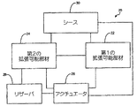
図1は、本発明の一実施形態による医療デバイスの概略図である。医療デバイス20は、第1の拡張可能部材22と、第1の拡張可能部材22によって画定される内部体積または領域(図1には図示せず)の内部に少なくとも部分的に配設される第2の拡張可能部材24とを含む。第1の拡張可能部材22は、例えば、細長い本体に配設する、または組み込むことができる。同様に、第2の拡張可能部材24も、細長い本体に配設する、または組み込むことができる。特定の実施形態に関して以下でより詳細に説明されるように、第1の拡張可能部材22に、第1の切断部分(図1には図示せず)を配設することができる。切断部分は、第1の拡張可能部材22及び/又は第2の拡張可能部材24に結合される個別構成要素であってよく、あるいは第1の拡張可能部材22及び/又は第2の拡張可能部材24によって画定される鋭利な縁部及び表面であってもよい。
FIG. 1 is a schematic view of a medical device according to an embodiment of the present invention. The
いくつかの実施形態では、第1の拡張可能部材22は、シース30など第3の細長い本体の内腔の内部に配設することができ、シース30は、第1の拡張可能部材22を縮退された構成と拡張された構成との間で移動させるために使用することができる。例えば、第1の拡張可能部材22は、ニチノールなどの形状記憶材料で形成することができ、事前設定された拡張された構成を有することができる。第1の拡張可能部材22は、複数のアームを含み、ウィスクタイプ形状(a whisk-type shape)を有することができる。例えば、第1の拡張可能部材22は、複数のアームを画定するように外面に沿って切断(例えばレーザ切断)されたスリットを有する部分を有する管状部材から形成することができる。いくつかの実施形態では、第1の拡張可能部材22は、細長い本体に結合された個別構成要素であってよい。例えば、アームは、細長い本体に結合された1つまたは複数の個別構成要素として形成することができる。第1の拡張可能部材22は、シースの内腔の内部に配設された状態で、縮退された構成で拘束することができる。第1の拡張可能部材22がシースの内腔から解放される、または内腔の外側に配設されるとき、第1の拡張可能部材22は、その事前設定された拡張された構成にバイアスされる。別法として、第1の拡張可能部材22は、可撓性材料など(1つまたは複数の)他の材料で形成することができ、これは、第1の拡張可能部材22の内域の内部に配設されたバルーンなど別の構成要素の補助によって、第1の拡張可能部材22を拡張された構成に移動させることができるようにする。
In some embodiments, the first expandable member 22 can be disposed within the lumen of a third elongate body, such as the
上述されたように、第2の拡張可能部材24は、第1の拡張可能部材22によって画定される内部体積の内部に少なくとも部分的に配設される。第2の拡張可能部材24は、縮退された構成と、拡張された構成とを有する。第2の拡張可能部材24は、例えば、拡張可能な可撓性材料から少なくとも一部を形成することができる。例えば、第2の拡張可能部材24は、バルーンを含むことができる。いくつかの実施形態では、第2の拡張可能部材24は、別法として、ニチノールなどの形状記憶材料で形成することができ、例えば、第1の拡張可能部材22に関して上述されたアームと同様の複数の拡張可能なリブを含むことができる。例えば、第2の拡張可能部材24は、外壁に沿って切断されたスリットを有する管状部材で形成することができ、第1の拡張可能部材22と同様のウィスク形状を有することができる。 As described above, the second expandable member 24 is at least partially disposed within the interior volume defined by the first expandable member 22. The second expandable member 24 has a collapsed configuration and an expanded configuration. The second expandable member 24 can be formed at least in part from, for example, an expandable flexible material. For example, the second expandable member 24 can include a balloon. In some embodiments, the second expandable member 24 can alternatively be formed of a shape memory material such as nitinol, eg, similar to the arm described above with respect to the first expandable member 22. A plurality of expandable ribs can be included. For example, the second expandable member 24 can be formed of a tubular member having a slit cut along the outer wall and can have a whisker shape similar to the first expandable member 22.
また、医療デバイス20は、アクチュエータ26も含むことができ、アクチュエータ26は、第1の拡張可能部材22と第2の拡張可能部材24とを、それらの当該の縮退された構成と拡張された構成との間で作動させるために使用することができる。いくつかの実施形態では、例えば、上述されたように、第1の拡張可能部材22は、シース30の内腔の内部に配設することができ、第2の拡張可能部材24は、第1の拡張可能部材22の内部領域の内部に配設することができる。シース30は、アクチュエータ26によって、第1の位置と第2の位置との間で移動または作動させることができる。シース30が第1の位置にあるとき、第1の拡張可能部材22と第2の拡張可能部材24とは、それらの縮退された構成で、シース30の内腔の内部に拘束される。シース30がその第2の位置に移動されるとき、第1の拡張可能部材22と第2の拡張可能部材24とはそれぞれ、シース30の内腔の外側に位置決めされ、それにより、第1の拡張可能部材22と第2の拡張可能部材24とが、それらの当該の拡張された構成に移動される。アクチュエータ26は、ハンドル(図1には図示せず)を含むことができ、シースをその第1の位置とその第2の位置との間で移動させるために使用者がそのハンドルを作動することができる。
The
いくつかの実施形態では、アクチュエータ26は、流体を内部に受け取って収容することができる内部領域を画定する任意選択のリザーバ28を含むことができる。リザーバ28は、第2の拡張可能部材24に結合させることができ、第2の拡張可能部材24に流体的に連通することができる。従って、第2の拡張可能部材24とリザーバ28とによって少なくとも一部を画定される閉じられた流体システムの内部に、流体を受け取って収容することができる。例えば、リザーバ28は、例えばシャフト、ホース、または他の部材(図1には図示せず)によって第2の拡張可能部材24に流体的に連通することができる。そのような実施形態では、シース30のその第2の位置への移動を作動させるのと同時に、閉じられた流体システムの内部に収容されている流体体積をリザーバ28の外に移動させることができ、それと共に、ある流体体積が第2の拡張可能部材24の中に移動される。シース30がその第2の位置に移動されると、第1の拡張可能部材22が解放されて、その拡張された構成にバイアスされる。第2の拡張可能部材24は、閉じられた流体システムの内部から、ある流体体積を受け取り、これが、第2の拡張可能部材24をその拡張された構成に移動させる。いくつかの実施形態では、拡張された構成にあるときの第2の拡張可能部材24の内部の流体体積は、拡張された構成での第2の拡張可能部材24が第1の拡張可能部材22の内部体積よりもわずかに大きい内部体積を有するようなものである。
In some embodiments, the actuator 26 can include an optional reservoir 28 that defines an interior region in which fluid can be received and housed. The reservoir 28 can be coupled to the second expandable member 24 and can be in fluid communication with the second expandable member 24. Accordingly, fluid can be received and contained within a closed fluid system defined at least in part by the second expandable member 24 and the reservoir 28. For example, the reservoir 28 can be in fluid communication with the second expandable member 24 by, for example, a shaft, hose, or other member (not shown in FIG. 1). In such an embodiment, the fluid volume contained within the closed fluid system can be moved out of the reservoir 28 at the same time as actuating the movement of the
使用時、医療デバイス20は、第1の拡張可能部材22と第2の拡張可能部材24とがそれらの縮退された構成にある状態で、椎体など患者の生体または組織内に経皮的に挿入することができる。いくつかの実施形態では、医療デバイス20は、組織部位へのアクセスを得るために使用される個別のカニューレ(cannula)を通して挿入される。医療デバイス20は、例えばハンドルを使用して、第1の拡張可能部材22と第2の拡張可能部材24とをそれらの拡張された構成に移動させるために作動させることができる。第1の拡張可能部材22と第2の拡張可能部材24とがそれらの拡張された構成にあり、組織内部に配設された状態で、医療デバイス20を回転させることができ、それにより、第1の拡張可能部材22及び/又は第2の拡張可能部材24にある切断部分が、組織部位で海綿骨などの組織を掻削または他の方法で切断する。以下でより詳細に説明されるように、第2の拡張可能部材24は、掻削または破壊された組織の少なくとも一部分が第1の拡張可能部材22の内部領域の中に入るのを妨げる助けとなるように、ブロックとして使用することができる。破壊された組織の少なくとも一部分が第1の拡張可能部材122の内部領域の内部に停留されるのを妨げることは、第1の拡張可能部材122の縮退及び取外しの補助となりうる。次いで、第1の拡張可能部材22と第2の拡張可能部材24とを、それらの縮退された構成に作動または移動させることができ、医療デバイス20を組織から取り外すことができるようにする。
In use, the
いくつかの実施形態では、医療デバイス20は、ただ1つの拡張可能部材のみを含む。そのような実施形態では、拡張可能部材は、上述されたのと同様のシースを使用して、またはプッシュロッドもしくはプルロッドの使用によって、拡張された構成と縮退された構成との間で移動させることができる。いくつかの実施形態では、シースが、プッシュロッドまたはプルロッドと関連して使用される。いくつかの実施形態では、医療デバイス20は、細長い部材(図1には図示せず)を含む。細長い部材は、拡張可能部材によって画定される内部領域から組織片(例えば、骨片)を排出するために使用することができる。また、細長い部材は、内部領域の中に流体を導入するように、及び/又は拡張可能部材の内部領域の内部から組織片を除去するために吸引を提供するように構成することもできる。
In some embodiments, the
様々な全般的な例を上述してきたが、以下、特定の実施形態のいくつかの例を説明する。これらの実施形態は、単に例にすぎず、医療デバイス20の多くの他の構成が企図される。
While various general examples have been described above, some examples of specific embodiments are described below. These embodiments are merely examples, and many other configurations of the
図2乃至図11は、本発明の一実施形態による医療デバイスを例示する。図2に示されるように、医療デバイス120は、シース130の内腔136の内部に配設される第1の細長い本体122と、第1の細長い本体122の内腔138の内部に少なくとも部分的に配設される第2の細長い本体124とを含む。また、第2の細長い本体124も、内腔146(図8及び図9に図示される)を画定する。図2及び図3はそれぞれ、医療デバイス120の一部分の側面図であり、断面図でのシース130と、部分断面図での第1の細長い本体122とを示す。第1の細長い本体122は、図2及び図4に示されるような縮退された構成と、図3及び図5に示されるような拡張された構成とを有する。第2の細長い本体124は、図2及び図6に示されるような縮退された構成と、図3及び図7に示されるような拡張された構成とを有する。この実施形態では、第1の細長い本体122は、間に開口部148を画定する複数のアーム140を含む遠位端部132に配設された拡張可能部材を有する。また、第1の細長い本体122は、第1の細長い本体122のアーム140に配設された切断部分154も含む。第2の細長い本体124は、遠位端部134にある可撓性膜など拡張可能部材を有する可撓性部材である。例えば、可撓性膜は、バルーンであってよい。遠位端部134は、第1の細長い本体122の遠位端部132の内部に少なくとも部分的に配設される。
2-11 illustrate a medical device according to one embodiment of the present invention. As shown in FIG. 2, the
第1の細長い本体122は、第1の細長い本体122が縮退された構成(図2、図4、及び図8)にあるときよりも、拡張された構成(図3、図5、及び図9)にあるときに大きい内部領域または体積142を画定する。第1の細長い本体122は、例えば、アーム140を形成するために遠位端部132の壁に切断(例えばレーザ切断)されたスリットを有する管状部材から形成することができる。また、第1の細長い本体122は、遠位端部132が拡張された構成にバイアスされるように、ニチノールなどの形状記憶材料で形成される。
The first
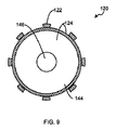
また、第2の細長い本体124の遠位端部134は、図9の断面図に最も良く示されるように、内部領域144を画定し、この内部領域144は、第2の細長い本体124が縮退された構成にあるときよりも、拡張された構成にあるときに大きい。上述されたのと同様に、この実施形態では、第2の細長い本体124の遠位端部134は、バルーンなどの可撓性部材である。いくつかの実施形態では、第2の細長い本体124は、モノリシックに形成される。代替実施形態では、第2の細長い本体124の異なる部分が、異なる材料で形成される。例えば、いくつかの実施形態では、第2の細長い本体124は、可撓性材料で全体を形成される。別の代替実施形態では、遠位端部134が、可撓性材料で形成され、第2の細長い本体124の残りの部分が、非可撓性材料で形成される。
The
図2、図3、図9、及び図10に示されるように、第2の細長い本体124の遠位端部134は、第1の細長い本体122の遠位端部132の内部に配設される。いくつかの実施形態では、第2の細長い本体124が第1の細長い本体122の内部領域142よりもわずかに大きいサイズに拡張し、第2の細長い本体124の遠位端部134がアーム140によって画定される開口部148の中に部分的に拡張するように、第2の細長い本体124の遠位端部134を形成することができる。
As shown in FIGS. 2, 3, 9, and 10, the
また、医療デバイス120は、図10及び図11に示されるようなアクチュエータ126を含む。アクチュエータ126は、使用者が作動することができるハンドル150と、ハウジング152とを含む。図10及び図11は、医療デバイス120の内域の一部分を見ることができるようにハウジング152の一部分が除去された状態で、医療デバイス120を示す。図10は、医療デバイス120を縮退された構成で例示し、図11は、医療デバイス120を拡張された構成で例示する。ハンドル150は、シース130に動作可能に結合され、また、リザーバ128及び摺動部材168にも動作可能に結合される。リザーバ128は、内部領域129を画定する。リザーバ128は、内部領域129の内部に流体を受け取って収容することができ、シャフト156を通して、かつ第2の細長い本体124の内腔146を通して、第2の細長い本体124に流体的に連通する。いくつかの実施形態では、シャフト156は、第2の細長い本体124と一体に形成される。いくつかの実施形態では、シャフトは、ハウジング150の外側に少なくとも部分的に配設される。従って、第2の細長い本体124と、リザーバ128と、シャフト156とが、以下でより詳細に説明されるような閉じられた流体システムを画定する。医療注射器プランジャなどのプランジャ158が、リザーバ128の内部に配設される。プランジャ158と摺動部材168とは、コンパートメント160の内部に配設された圧縮ばねなどのばね(図示せず)に結合される。また、プランジャ158は、枢動アーム162を介してハンドル150にも結合される。ばねは、ハンドル150を、図11に示されるような開いた位置にバイアスする。
The
医療デバイス120を拡張された構成から縮退された構成に移動させるために、使用者は、図10に示されるようにハンドル150がハウジング152に向けて移動されるようにアクチュエータ126のハンドル150を把持する。この作用が、シース130を第1の位置に向けて遠位方向に移動させ、この第1の位置で、シース130の遠位端164が、第1の細長い本体122の遠位端部132の実質的に上に位置決めされる(例えば、遠位端部132が、シース130の内腔136の内部に少なくとも部分的に配設される)。この作用は、第1の細長い本体122の遠位端部132を縮退させる。同時に、プランジャ128が、ばねコンパートメント160に向けて移動され、ばねを少なくとも一部圧縮する。第2の細長い本体124の遠位端部134の中の流体体積が、遠位端部134から引き出され、ある流体体積がリザーバ128に引き入れられる。すなわち、閉じられた流体システムの内部の流体の一部が、リザーバ128に移動させられる。遠位端部134から出る流体移動は、第1の細長い本体122の遠位端部132が、第2の細長い本体124の遠位端部134の上に縮退することができるようにする。従って、縮退された構成では、第2の細長い本体124の遠位端部134の内部にある流体体積は、第2の細長い本体124が拡張された構成にあるときに遠位端部134の中にある流体体積よりも小さい。第2の細長い本体124の遠位端部134が縮退された構成にあるときにリザーバ128の内部にある流体体積は、第2の細長い本体124の遠位端部134が拡張された構成にあるときにリザーバ128の中にある流体体積よりも大きい。
To move the
縮退された構成で、医療デバイス120は、椎体など患者の組織内に挿入することができる。例えば、医療デバイス120は、使用者が図10に示されるようにハウジング152に対してハンドル150を保持した状態で、アクセスカニューレ(図示せず)を通して挿入することができる。組織内部に配設された状態で、使用者は、ハンドル150を解放することができ、これにより、図11に示されるように、ばねが、ハンドル150を開いた位置にバイアスして戻す。この作用は、シース130の遠位端164を近位方向に移動させ、それにより、図11に示されるように、第1の細長い本体122がシース130の内腔136の外側に配設される。第1の細長い本体122の遠位端部132がもはやシース130によって拘束されないとき、遠位端部132は、拡張された構成に自動的にバイアスされる。同時に、プランジャ128は、(例えば、ばねのバイアス力により)ばねコンパートメント160から移動して離れ、流体をリザーバ128から出して、シャフト156内に押し進める。第1の細長い本体122の遠位端部132が拡張された構成にある状態で、第2の細長い本体124の遠位端部134は、リザーバ128から押し出された流体体積を受け取り、その拡張された構成に移動することができる。
In the collapsed configuration, the
拡張された構成で、医療デバイス120は、組織内部で回転または他の方法で移動させることができ、それにより、第1の細長い本体122の遠位端部132に配設された切断部分154が、組織内部で海綿骨などの組織を掻削、断裂、または他の方法で破壊する。第2の細長い本体122の遠位端部134は、掻削、断裂、または破壊された組織の少なくとも一部分が第1の細長い本体122の内部領域142の中に入るのを阻止する。
In the expanded configuration, the
医療デバイス120を縮退された構成に移動させて戻すために、使用者は、図10に示されるようにハンドル150がハウジング152に近づくように移動されるように、再びハンドル150を把持する。これは、上述されたように、医療デバイス120を縮退された構成に再び移動させる。次いで、使用者は、例えばアクセスカニューレを通して、医療デバイス120を組織から取り外すことができる。
To move the
第1の細長い本体122は、事前設定された拡張された構成を有する形状記憶材料で形成されるものとして説明されてきたが、代替実施形態では、第1の細長い本体122は、形状記憶特性を有さない他の材料で形成することができる。そのような実施形態では、第2の細長い本体124をその拡張された構成に作動させることによって、第1の細長い本体122をその拡張された構成に移動させることができる。例えば、第2の細長い本体124は、上述されたように、第2の細長い本体124の内部領域の内部に流体が受け取られるときに、拡張された構成に移動させることができる。これが生じるとき、第2の細長い本体124の拡張が、第1の細長い本体122も拡張させる。第1の細長い本体122を縮退させるためには、上述されたように、使用者がハンドル150を把持することができ、使用者は、シース130を、第1の細長い本体122の遠位端部132の上に遠位方向に移動させ、第1の細長い本体122の遠位端部132を縮退させる。1つの変形形態では、第1の細長い本体122は、形状記憶材料で形成することができ、縮退された構成にバイアスすることができる。この実施形態では、第2の細長い本体124が縮退されるとき、第1の細長い本体122は、シースを使用せずに、その縮退された構成にバイアスされて戻される。
Although the first
医療デバイス120の作動は、医療デバイス120を縮退された構成に移動させるためにハンドル150を把持し、医療デバイス120を拡張された構成に移動させるためにハンドル150を解放するものとして説明されてきたが、代替実施形態では、ハンドル150を逆の様式で作動させることができる。例えば、医療デバイスは、使用者が、医療デバイスを拡張された構成に移動させるためにハウジングに対してハンドルを把持し、医療デバイスを縮退された構成に移動させるためにハンドルを解放することができるように構成することができる。他の代替実施形態では、ハンドルは、直線移動で作動させることができる。例えば、医療デバイスを作動させるためにハウジングに対してハンドルを把持するのではなく、注射器の移動と同様の直線運動で使用者がハンドルを作動するように、ハンドルが、第1の細長い本体及び/又は第2の細長い本体によって定義される軸に平行に延在することができる。
Operation of the
更に別の実施形態では、医療デバイス120は、細長いシャフトを通して第2の細長い本体に流体的に連通するリザーバを使用して作動させることができる。そのような実施形態では、リザーバと第2の細長い本体とは、上述されたのと同様に、閉じられた流体システムを画定することができ、ある流体体積が、遠位端部を拡張された構成に移動させるために第2の細長い本体の遠位端部の中に移動され、遠位端部を縮退された構成に移動させるために遠位端部から引き出される。この実施形態では、第2の細長い本体を縮退された構成から拡張された構成に作動させるために、使用者は、リザーバを圧搾することができ、それにより、ある流体体積がリザーバから押し出され、ある流体体積が第2の拡張可能部材の遠位端部の中に移動される。
In yet another embodiment, the
そのような実施形態では、第1の細長い本体の遠位端部は、形状記憶材料で形成することができ、縮退された構成にバイアスさせることができる。第2の細長い本体の遠位端部がその拡張された構成に移動されるとき、第2の拡張可能部材の膨張によって、第1の細長い本体も、その拡張された構成に移動される。リザーバが解放されるとき、ある流体体積がリザーバの中に引き戻され、ある流体体積が第2の細長い本体の遠位端部から引き出され、第2の細長い本体の遠位端部を縮退させる。第2の細長い本体の遠位端部が縮退されると、第1の細長い本体は、その縮退された構成にバイアスされて戻される。 In such embodiments, the distal end of the first elongate body can be formed of a shape memory material and can be biased to a collapsed configuration. When the distal end of the second elongate body is moved to its expanded configuration, the expansion of the second expandable member also moves the first elongate body to its expanded configuration. When the reservoir is released, a fluid volume is drawn back into the reservoir and a fluid volume is withdrawn from the distal end of the second elongate body, causing the distal end of the second elongate body to retract. When the distal end of the second elongate body is retracted, the first elongate body is biased back to its collapsed configuration.
図12乃至図15は、別の実施形態による医療デバイスを例示する。医療デバイス220は、シース230の内腔236の内部に配設された第1の細長い本体222と、第1の細長い本体222の内腔238の内部に少なくとも部分的に配設された第2の細長い本体224とを含む。また、第2の細長い本体224も、内腔246(図13に図示される)を画定する。図12及び図13は、医療デバイス220の一部分の側面図であり、断面図でのシース230と、部分断面図での第1の細長い本体222とを示す。第1の細長い本体222は、縮退された構成(図示せず)と、図12及び図13に示されるような拡張された構成とを有する。第2の細長い本体224は、縮退された構成(図示せず)と、図12及び図13に示されるような拡張された構成とを有する。
12-15 illustrate a medical device according to another embodiment. The
この実施形態では、第1の細長い本体222は、間に開口部248を画定する複数のアーム240を含む遠位端部232を有する。また、第1の細長い本体222は、第1の細長い本体222のアーム240に配設された切断部分254も含む。第2の細長い本体224は、遠位端部234を有し、この遠位端部234は、複数のリブ266を画定し、リブ266がアーム240とオフセット関係になるように第1の細長い本体222の遠位端部232の内部に少なくとも部分的に配設される。また、第2の細長い本体224は、リブ266に配設された切断部分270も含む。代替実施形態では、第2の細長い本体224は、切断部分を含まない。
In this embodiment, the first
前述の実施形態と同様に、第1の細長い本体222は、第1の細長い本体222が縮退された構成にあるときよりも、拡張された構成にあるときに大きい内部領域または体積(図示せず)を画定する。第1の細長い本体222は、前述の実施形態で説明されたのと同じ様式で、例えば、アーム240を形成するために遠位端部232に切断されたスリットを有する管状部材から形成することができる。また、第1の細長い本体222は、遠位端部232が拡張された構成を取るようにバイアスされるように、ニチノールなどの形状記憶材料で形成される。
Similar to the previous embodiment, the first
また、第2の細長い本体224の遠位端部234は、第2の細長い本体224が縮退された構成にあるときよりも、拡張された構成にあるときに大きい内部領域(図示せず)を画定する。この実施形態では、第2の細長い本体224は、遠位端部234が事前設定された拡張された構成を有するように、形状記憶材料で形成される。例えば、第2の細長い本体224の遠位端部234は、リブ266を画定するために外壁に沿って切断されたスリットを有するように形成することができる。図12及び図13に示されるように、第2の細長い本体224の遠位端部234は、アーム240によって画定される開口部248の内部にリブ266が実質的に配設されるように、第1の細長い本体222の遠位端部232の内部に配設される。
Also, the
また、医療デバイス220は、図14及び図15に示されるようなアクチュエータ226も含む。アクチュエータ226は、使用者が作動することができるハンドル250と、ハウジング252とを含む。図14及び図15は、医療デバイス220の内域の一部分を見ることができるようにハウジング252の一部分が除去された状態で、医療デバイス220を示す。図14は、医療デバイス220を縮退された構成で例示し、図15は、医療デバイス220を拡張された構成で例示する。この実施形態では、ハンドル250は、前述の実施形態で説明されたのと同様に、シース230に動作可能に結合され、また、枢動アーム262を介して摺動部材268にも動作可能に結合される。摺動部材268は、コンパートメント260の内部に配設された圧縮ばねなどのばね(図示せず)に結合される。前述の実施形態と同様に、ばねは、ハンドル250を、図15に示されるような開いた位置にバイアスする。
The
医療デバイス220を拡張された構成から縮退された構成に移動させるために、使用者は、図14に示されるようにハンドル250がハウジング252に向けて移動されるようにハンドル250を把持する。この作用が、シース230を第1の位置に向けて遠位方向に移動させ、この第1の位置で、シース230の遠位端264が、第1の細長い本体222の遠位端部232の実質的に上に位置決めされる。従って、第1の細長い本体222の遠位端部232と第2の細長い本体224の遠位端部234とは、シース230の内腔236の内部で、それらの当該の縮退された構成に拘束される。
To move the
縮退された構成で、医療デバイス220は、椎体など患者の組織内に挿入することができる。例えば、医療デバイス220は、アクセスカニューレを通して挿入することができる。組織内部に配設された状態で、使用者は、ハンドル250を解放することができ、医療デバイス220を拡張された構成に移動させる。ハンドル250が解放されると、図15に示されるように、ばねが、ハンドル250を開いた位置にバイアスする。この作用は、シース230の遠位端264を近位方向に移動させ、それにより、図15に示されるように、第1の細長い本体222の遠位端部232(及び第1の細長い本体222の内部に配設された第2の細長い本体224の遠位端部234)が、シース230の内腔236の外側に配設される。第1の細長い本体222の遠位端部232と第2の細長い本体224の遠位端部234とがもはやシース230によって拘束されないとき、遠位端部232と遠位端部234とは、それらの当該の拡張された構成に自動的にバイアスされる。
In the collapsed configuration, the
拡張された構成で、医療デバイス220は、組織内部で回転または他の方法で移動させることができ、それにより、第1の細長い本体222の切断部分254と、第2の細長い本体224の切断部分270とが、組織内部で海綿骨などの組織を掻削、断裂、または他の方法で破壊する。第2の細長い本体222の遠位端部234のリブ266がアーム240とオフセット関係に配設される(すなわち、開口部248の内部に配設される)ので、リブ266は、断裂または破壊された組織の少なくとも一部分が第1の細長い本体222の内部領域の中に入るのを阻止する。
In the expanded configuration, the
医療デバイス220を縮退された構成に移動させて戻すために、使用者は、図14に示されるようにハンドル250がハウジング252に近づくように移動されるように、再びハンドル250を把持する。これは、ここでも上述されたのと同様に、医療デバイス220を縮退された構成に移動させる。次いで、使用者は、例えばアクセスカニューレを通して、医療デバイス220を組織から取り外すことができる。
To move the
図16及び図17は、医療デバイスの更に別の実施形態を例示する。医療デバイス320は、医療デバイス120と同様に構成される。例えば、医療デバイス320は、シース330と、シース330の内腔(図示せず)の内部に配設された第1の細長い本体322と、第1の細長い本体322の内腔(図示せず)の内部に配設された第2の細長い本体324とを含む。この実施形態では、第1の細長い本体322は、複数のアーム340と、アーム340に配設された切断部分354とを有する遠位端部332を含む。この実施形態では、アーム340は、管状部材から形成されるのではなく、例えばニチノールなど可撓性の形状記憶材料を用いて1つまたは複数の個別構成要素として形成し、第1の細長い本体322に結合させることができる。
16 and 17 illustrate yet another embodiment of the medical device. The
第2の細長い本体324は、第1の細長い本体322の遠位端部332の内部に配設される遠位端部334に可撓性膜を含む。また、第2の細長い本体324は、図17に示されるように内腔346を画定する。内腔346は、前述されたのと同様に、第2の細長い本体324の遠位端部334とリザーバ(図示せず)との間で流体を連通するために使用することができる。
The second
この実施形態では、遠位端部332は、拡張された構成にバイアスされ、4つのアーム340を含み、アーム340はそれぞれ、ヒンジまたは屈曲点372を含む。屈曲点372は、第1の細長い本体324が縮退された構成から拡張された構成に移動されるときに屈曲する。医療デバイス320は、医療デバイス120に関して上述されたのと同様の様式で、拡張された構成と縮退された構成との間で移動させることができる。
In this embodiment,
別の代替実施形態では、医療デバイスは、第1の細長い本体の拡張を作動させるためにプルロッドを含むことができる。そのような実施形態では、シースは必要なくなる。プルロッドは、第2の細長い本体の作動と同時に第1の細長い本体を作動させることができるように、アクチュエータに動作可能に結合させることができる。例えば、ウィスクタイプ構成を有する第1の細長い本体の内部に配設される可撓性部材(例えば、バルーン)を有する第2の細長い本体を用いる実施形態では、可撓性部材は、プルロッドを受け取るために通路を有するように構成することができる。プルロッドは、第1の細長い本体の可撓性部材の内部での流体の増加と同時に、第1の細長い本体を拡張された構成に移動させるために近位方向に引っ張ることができる。バルーンの代わりにウィスクタイプ構成を有する第2の細長い本体を用いる実施形態では、プルロッドは、第1の細長い本体と第2の細長い本体とを同時に作動させるように構成することができる。 In another alternative embodiment, the medical device can include a pull rod to actuate expansion of the first elongate body. In such embodiments, a sheath is not necessary. The pull rod can be operably coupled to the actuator such that the first elongate body can be activated simultaneously with the activation of the second elongate body. For example, in embodiments using a second elongate body having a flexible member (eg, a balloon) disposed within a first elongate body having a whiskey type configuration, the flexible member receives a pull rod. Therefore, it can be configured to have a passage. The pull rod can be pulled proximally to move the first elongate body to the expanded configuration simultaneously with the increase in fluid within the flexible member of the first elongate body. In embodiments that use a second elongate body having a whiskey type configuration instead of a balloon, the pull rod can be configured to actuate the first elongate body and the second elongate body simultaneously.
更に別の実施形態では、医療デバイスは、ウィスクタイプの第1の細長い本体の内部に配設される可撓性膜を有する第2の細長い本体を含むことができる。この実施形態では、第1の細長い本体のアームは、可撓性膜に固定される。そのような実施形態では、第1の細長い本体を作動させるのに、シースは必要なくなる。例えば、上述されたのと同様に、可撓性膜が流体によって膨張されて、その拡張された構成に移動されるとき、第1の細長い本体も、その拡張された構成に移動される。デバイスを縮退された構成に移動させるためには、前述されたのと同様に、流体を可撓性膜から引き出すことができる。流体が可撓性膜から排出されるとき、第1の細長い本体も、その縮退された構成に導かれる。 In yet another embodiment, the medical device can include a second elongate body having a flexible membrane disposed within the first elongate body of the whisk type. In this embodiment, the arms of the first elongate body are secured to the flexible membrane. In such embodiments, a sheath is not required to actuate the first elongate body. For example, as described above, when the flexible membrane is expanded by the fluid and moved to its expanded configuration, the first elongate body is also moved to its expanded configuration. To move the device to the collapsed configuration, fluid can be withdrawn from the flexible membrane, as described above. As fluid is expelled from the flexible membrane, the first elongate body is also guided to its collapsed configuration.
図18及び図19は、縮退された構成と拡張された構成との間で医療デバイスを作動させるためにプッシュロッドを使用する医療デバイスの実施形態を例示する。この実施形態では、医療デバイス420は、図19に示されるような縮退された構成と、図18に示されるような拡張された構成との間で移動可能な細長い本体422を含む。細長い本体422は、内腔(図示せず)を画定し、間に開口部448を画定する複数のアーム440を含む遠位端部432を有する。アーム440の縁部が、切断部分454を画定する。また、医療デバイス420は、ロッド425を含み、このロッド425は、細長い本体422の内腔の内部に少なくとも部分的に配設される。ロッド425の遠位端は、細長い本体422の遠位端427に結合される。
18 and 19 illustrate an embodiment of a medical device that uses a push rod to actuate the medical device between a collapsed configuration and an expanded configuration. In this embodiment, the
前述の実施形態と同様に、細長い本体422は、ニチノールなどの形状記憶材料で形成することができ、細長い本体422の遠位端部432が図18に示されるように拡張された構成にバイアスされるように構成することができる。細長い本体422は、前述の実施形態で説明されたのと同じ様式で、例えば、アーム440を形成するために遠位端部432に切断されたスリットまたは窓を有する管状部材から形成することができる。細長い本体422が拡張された構成にあるとき、アーム440は、細長い本体422が縮退された構成にあるときよりも大きい内部領域または体積449を画定する。
Similar to the previous embodiment, the
ロッド425は、近位端431でアクチュエータ426に結合される。アクチュエータ426は、ハンドル450とハウジング452とを含む。図18は、医療デバイス420の内域の一部分を見ることができるようにハウジング452の一部分が除去された状態で、医療デバイス420を示す。この実施形態では、ハンドル450は、ロッド425に動作可能に結合され、ロッド425が、細長い本体422をその拡張された構成と縮退された構成との間で移動させるために使用される。ハンドル450は、枢動アーム462を介して摺動部材468に結合される。また、摺動部材468が、コンパートメント460の内部に配設された圧縮ばねなどのばね(図示せず)に結合される。摺動部材468は、ばねがバイアスされた位置と圧縮された位置との間で移動するときに、矢印A−Aの方向で前後に移動または並進することができる。前述の実施形態と同様に、ばねは、そのバイアスされた位置にあるとき、ハンドル450を、図18に示されるような開いた位置にバイアスする。ハンドル450が開いた位置にあるとき、ロッド425は、図18に示されるような位置に向けて近位方向に移動される。これは、細長い本体422の遠位端部432(例えばアーム440)を少なくとも部分的に縮退させる。
細長い本体422を拡張された構成から縮退された構成に移動させるために、使用者は、図19に示されるようにハンドル450がハウジング452に向けて移動されるようにハンドル450を把持する。この作用が、ばねを圧縮し、ロッド425を遠位方向に移動させ、これが更に、細長い本体422の遠位端部432(例えばアーム440)を伸張または縮退させる。
To move the
縮退された構成で、医療デバイス420は、椎体など患者の組織内に挿入することができる。例えば、使用者は、上述されたようにハンドル450を把持して、医療デバイス420を、アクセスカニューレを通して組織内部の所望の位置に挿入することができる。組織内部に配設された状態で、使用者は、ハンドル450を解放することができ、医療デバイス420を拡張された構成に移動させる。ハンドル450が解放されると、ばねは、ハンドル450を、図18に示されるような開いた位置にバイアスし、ロッド425を近位方向に移動させ、それにより、細長い本体422の遠位端部432が、拡張された構成に移動される。拡張された構成で、医療デバイス420は、組織内部で回転または他の方法で移動させることができ、それにより、アーム440の切断部分454が、組織内部で海綿骨などの組織を掻削、断裂、または他の方法で破壊する。
In the collapsed configuration, the
医療デバイス420を縮退された構成に移動させて戻すために、使用者は、図19に示されるようにハンドル450がハウジング452に近づく向きに移動されるように、再びハンドル450を把持する。これは、ここでも上述されたのと同様に、医療デバイス420を縮退された構成に移動させる。次いで、使用者は、例えばアクセスカニューレを通して、医療デバイス420を組織から取り外すことができる。
To move the
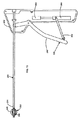
図20及び図21は、医療デバイスを縮退された構成と拡張された構成との間で作動させるために使用することができるプルロッドを有する医療デバイスの実施形態を例示する。この実施形態では、医療デバイスのハンドルは、医療デバイスを拡張された構成に移動させるために把持され、医療デバイスを縮退された構成に移動させるために解放される。医療デバイス520は、図20に示されるような縮退された構成と、図21に示されるような拡張された構成との間で移動可能な細長い本体522を含む。細長い本体522は、内腔(図示せず)を画定し、間に開口部548を画定する複数のアーム540を含む遠位端部532を有する。アーム540の縁部が、切断部分554を画定する。また、医療デバイス520は、ロッド525を含み、このロッド525は、細長い本体522の内腔の内部に少なくとも部分的に配設される。ロッド525の遠位端(図示せず)は、細長い本体522の遠位端527に結合され、ロッド525の近位端531は、アクチュエータ526に結合される。
20 and 21 illustrate an embodiment of a medical device having a pull rod that can be used to operate the medical device between a collapsed configuration and an expanded configuration. In this embodiment, the handle of the medical device is grasped to move the medical device to the expanded configuration and released to move the medical device to the collapsed configuration. The
前述の実施形態と同様に、細長い本体522は、ニチノールなどの形状記憶材料で形成することができる。この実施形態では、細長い本体532は、細長い本体522の遠位端部532が図20に示されるように縮退された構成にバイアスされるように構成することができる。細長い本体522は、前述の実施形態で説明されたのと同じ様式で、例えば、アーム540を形成するために遠位端部532に切断されたスリットまたは窓を有する管状部材から形成することができる。細長い本体520が拡張された構成にあるとき、アーム540は、細長い本体522が縮退された構成にあるときよりも大きい内部領域または体積549を画定する。
Similar to the previous embodiment, the
アクチュエータ526は、ハンドル550とハウジング552とを含む。図20は、医療デバイス520の内域の一部分を見ることができるようにハウジング552の一部分が除去された状態で、医療デバイス520を示す。この実施形態では、ハンドル550は、ロッド525に動作可能に結合され、ロッド525が、細長い本体522をその拡張された構成と縮退された構成との間で移動させるために使用される。ハンドル550は、枢動アーム562を介して摺動部材568に結合される。また、摺動部材568は、コンパートメント560の内部に配設された圧縮ばねなどのばね(図示せず)に結合される。摺動部材568は、ばねがバイアスされた位置と圧縮された位置との間で移動するときに、前述の実施形態と同様に前後に移動または並進することができる。バイアスされた位置にあるばねは、ハンドル550を、図20に示されるような開いた位置にバイアスし、ロッド525は、図20に示されるような位置に向けて遠位方向に移動される。この位置で、細長い本体522は、その縮退された構成にある。
細長い本体522を縮退された構成から拡張された構成に移動させるために、使用者は、図21に示されるようにハンドル550がハウジング552に向けて移動されるようにハンドル550を把持する。この作用が、ばねを圧縮し、ロッド525を近位方向に移動させ、これが更に、細長い本体522の遠位端部532(例えばアーム540)をその拡張された構成に移動させる。
To move the
前述の実施形態と同様に、縮退された構成にあるとき、医療デバイス520は、椎体など患者の組織内に挿入することができる。例えば、医療デバイス520は、アクセスカニューレを通して、組織内部の所望の位置に挿入することができる。組織内部に配設された状態で、使用者は、ハンドル550を把持することができ、医療デバイス520を拡張された構成に移動させる。拡張された構成で、医療デバイス520は、組織内部で回転または他の方法で移動させることができ、それにより、アーム540の切断部分554が、組織内部で海綿骨などの組織を掻削、断裂、または他の方法で破壊する。この実施形態では、医療デバイス520を縮退された構成に移動させて戻すために、使用者がハンドル550を解放する。
Similar to the previous embodiment, when in a collapsed configuration, the
図22は、医療デバイス220(図14及び図15)と同様の医療デバイスの実施形態を例示し、ただし、この実施形態では、医療デバイスは、シースの作動によって、縮退された構成と拡張された構成との間で移動可能なただ1つの細長い本体のみを含む。医療デバイス620は、シース630の内腔(図示せず)の内部に配設された細長い本体622を含む。細長い本体622は、縮退された構成(図示せず)と、図22に示されるような拡張された構成との間で移動可能である。
FIG. 22 illustrates an embodiment of a medical device similar to the medical device 220 (FIGS. 14 and 15), but in this embodiment, the medical device has been expanded and contracted by actuation of the sheath. It includes only one elongated body that is movable between the configurations. The
この実施形態では、細長い本体622は、間に開口部648を画定する複数のアーム640を含む遠位端部632を有する。アーム640は、アーム640の縁部に配設された切断部分654を画定する。前述の実施形態と同様に、細長い本体622は、細長い本体622が縮退された構成にあるときよりも、拡張された構成にあるときに大きい内部領域または体積649を画定する。細長い本体622は、前述の実施形態で説明されたのと同じ様式で、例えば、アーム640を形成するために遠位端部632に切断されたスリットを有する管状部材から形成することができる。また、細長い本体622は、遠位端部632が拡張された構成を取るようにバイアスされうるように、ニチノールなどの形状記憶材料で形成される。
In this embodiment, the
また、医療デバイス620は、使用者が作動することができるハンドル650と、ハウジング652とを含むアクチュエータ626を含む。この実施形態では、ハンドル650は、シース630に動作可能に結合され、かつ枢動アーム662を介して摺動部材668に動作可能に結合される。摺動部材668は、ばね(図示せず)に結合され、ばねは、ハンドル650を、図22に示されるような開いた位置にバイアスさせる。ハンドル650がその開いた位置に移動されると、医療デバイス620のシース630は近位方向に移動され、それにより、シース630の遠位端664が、遠位端部632の少なくとも一部分を露出して、拡張された構成に移動させる。
The
医療デバイス620を拡張された構成から縮退された構成に移動させるために、使用者は、ハンドル650がハウジング652に向けて移動されるようにハンドル650を把持する。この作用は、シース630の遠位端664が第1の細長い本体622の遠位端部632の実質的に上に位置決めされる位置(図示せず)に向けて、シース630を遠位方向に移動させる。従って、細長い本体622の遠位端部632は、シース630の内腔の内部で、その縮退された構成に拘束される。
To move the
前述の実施形態と同様に、縮退された構成にあるとき、医療デバイス620は、(例えばアクセスカニューレを通して)患者の組織内に挿入することができる。組織内部に配設された状態で、使用者は、ハンドル650を解放することができ、医療デバイス620を拡張された構成に移動させる。この作用は、シース630の遠位端664を近位方向に移動させ、それにより、図22に示されるように、細長い本体622の遠位端部632が、シース630の内腔の外側に配設され、その拡張された構成に自動的にバイアスされる。拡張された構成で、医療デバイス620は、組織内部で回転または他の方法で移動させることができ、それにより、細長い本体622の切断部分654が、組織内部で海綿骨などの組織を掻削、断裂、または他の方法で破壊する。次いで、医療デバイス620を縮退された構成に移動させて戻して、医療デバイス620を組織から取り外すことができる。
Similar to the previous embodiments, when in a collapsed configuration, the
図23及び図24はそれぞれ、上述されたのと同様に組織を破壊するために使用することができ、また、椎骨の破砕を減少するために使用することができる医療デバイスの実施形態の遠位端部を例示する。医療デバイス720は、縮退された構成と拡張された構成との間での医療デバイス720の作動のためにプッシュロッドとシースとの両方を含む。拡張された構成で組織内部で展開されるとき、医療デバイス720は、組織の少なくとも一部分が偏位されるように、骨を含めた周囲組織に力を印加することが可能である。
FIGS. 23 and 24 are each distal to an embodiment of a medical device that can be used to break tissue as described above and can be used to reduce vertebral fracture. An end part is illustrated. The
具体的には、図23に示されるように、医療デバイス720は、細長い本体722と、シース730と、ロッド725とを含む。医療デバイス620と同様に、細長い本体722は、シース730の内腔(図示せず)の内部に移動可能に配設される。医療デバイス420及び520と同様に、ロッド725は、細長い本体722の内腔(図示せず)の内部に配設される。
Specifically, as shown in FIG. 23, the
細長い本体722は、前述の実施形態に関して説明されたのと同じ様式で、ニチノールなどの形状記憶材料で形成することができる。細長い本体722は、細長い本体722の壁にスロットまたは窓を切断することによって形成することができるアーム740を含む遠位端部732を含む。アーム740は、開口部748と内部領域749とを画定する。また、アーム740は、例えばアーム740の縁部に配設された切断部分754を含む。
The
ロッド725の遠位端(図示せず)は、細長い本体722の遠位端727に結合され、ロッド725の近位端(図示せず)は、アクチュエータ(図示せず)に結合される。アクチュエータは、例えば、前述の実施形態に関して上述されたようなアクチュエータであってよい。また、シース730が、近位端(図示せず)でアクチュエータに結合される。アクチュエータは、医療デバイス720を縮退された構成と拡張された構成との間で移動させるために、前述の実施形態に関して説明されたのと同じ様式で、ロッド725とシース730との両方を移動させるために使用することができる。
The distal end (not shown) of the
この実施形態では、細長い本体722の遠位端部732は、拡張された構成に事前設定(またはバイアス)される。使用時、医療デバイス720を組織内に挿入するために、アクチュエータのハンドル(図示せず)を把持することができ、それにより、シース730とロッド725との両方が遠位方向に(例えば実質的に同時に)移動または並進される。図24に示されるように、シース730の遠位端764は、細長い本体722の遠位端部732の少なくとも一部を覆う位置に移動し、遠位端部732を少なくとも部分的に縮退させる。同様に、ロッド725が遠位方向に移動されるとき、ロッド725は、細長い本体722の遠位端部732を縮退された構成に伸ばす。組織部位で所望の位置にくると、アクチュエータのハンドルを解放することができ、これは、ロッド725とシース730とを近位方向に移動させる。このとき、細長い本体722の遠位端部732は、シース730によって拘束されず、図23に示されるように、そのバイアスされた拡張された構成を取ることを可能にされる。同時に、ロッド725は、細長い本体722の遠位端部732を、拡張された構成に押し進める。従って、ロッド725は、細長い本体722の遠位端部732が拡張された構成に移動する速度及び力を増加する。
In this embodiment, the
縮退された構成から拡張された構成への細長い本体722の移動を作動させるためにプッシュロッド725とシース730との両方を使用することは、医療デバイス720が、作動中に、より大きな力を周囲組織に印加することができるようにする。これは、例えば、椎骨端板など硬い骨で使用されるときに有益となりうる。
Using both the
図25乃至図27はそれぞれ、拡張された構成と縮退された構成との間での医療デバイスの作動のためにロッドとシースとの両方を有する医療デバイスのさらなる実施形態の遠位端部を例示する。図25乃至図27を参照して説明される医療デバイスはそれぞれ、ロッドとシースとの両方を作動させるために、かつ細長い本体を拡張された構成と縮退された構成との間で移動させるために、上述されたようなアクチュエータを含むことができる。図25乃至図27の医療デバイスはそれぞれ、組織を破壊するために使用することができ、また上述したような破砕減少デバイスとしても使用することができる。 FIGS. 25-27 each illustrate the distal end of a further embodiment of a medical device having both a rod and a sheath for actuation of the medical device between an expanded configuration and a collapsed configuration. To do. Each of the medical devices described with reference to FIGS. 25-27 is for actuating both the rod and sheath and for moving the elongate body between an expanded configuration and a collapsed configuration. , Actuators as described above can be included. Each of the medical devices of FIGS. 25-27 can be used to disrupt tissue and can also be used as a crush reduction device as described above.
図25に示されるように、医療デバイス820は、細長い本体822と、シース830と、ロッド825とを含む。細長い本体822は、シース830の内腔(図示せず)の内部に配設される。ロッド725は、細長い本体822の内腔(図示せず)の内部に配設される。細長い本体822は、前述の実施形態に関して上述されたのと同じ様式で、ニチノールなどの形状記憶材料で形成することができ、図25に示されるような拡張された構成を取るように事前設定される。細長い本体822は、細長い本体822の壁にスロットまたは窓を切断することによって形成することができるアーム840を含む遠位端部832を含む。アーム840は、開口部848と内部領域849とを画定する。また、アーム840は、例えばアーム840の縁部に配設された切断部分854を含む。
As shown in FIG. 25, the
ロッド825の遠位端(図示せず)は、細長い本体822の遠位端827に結合され、ロッド825の近位端(図示せず)は、アクチュエータ(図示せず)に結合される。この実施形態では、遠位端827は、組織に貫入するために使用することができるように先細りにされる。そのような実施形態では、組織に貫入するための別個のツールは不要である。アクチュエータは、例えば、前述の実施形態に関して上述されたようなアクチュエータであってよい。また、シース830は、近位端(図示せず)でアクチュエータに結合される。アクチュエータは、前述の実施形態に関して説明されたのと同じ様式で、ロッド825とシース830との両方を移動させるために使用することができ、医療デバイス820を縮退された構成と拡張された構成との間で移動させる。
The distal end (not shown) of the
代替実施形態では、ロッドは、ロッドの遠位端と近位端との両方で内腔に連通する開口部を有する内部内腔を含むことができる。そのような実施形態では、細長い本体の遠位端が、ロッドの開口部に連通する開口部を画定することができる。ロッドの内腔を通して、かつロッドと細長い本体との遠位開口部を通して、流体を組織内に導入することができる。また、ロッドの内腔と、ロッドと細長い本体との両方での遠位開口部とは、組織から材料を吸引するために使用することもできる。いくつかの実施形態では、細長い本体の遠位端は、複数の開口部を有することができる。例えば、注射器をロッドの近位端に結合することができ、食塩水を導入するため、及び/又は例えば細長い本体の遠位端部(例えば、拡張された部分)の内部領域の内部から組織片を除去するために吸引を提供するために使用することができる。 In an alternative embodiment, the rod can include an internal lumen having openings that communicate with the lumen at both the distal and proximal ends of the rod. In such embodiments, the distal end of the elongate body can define an opening that communicates with the opening of the rod. Fluid can be introduced into the tissue through the lumen of the rod and through the distal opening of the rod and the elongated body. The rod lumen and the distal opening in both the rod and the elongate body can also be used to aspirate material from the tissue. In some embodiments, the distal end of the elongate body can have a plurality of openings. For example, a syringe can be coupled to the proximal end of the rod to introduce saline and / or tissue pieces from within the interior region of the distal end (eg, an expanded portion) of the elongate body, for example. Can be used to provide suction to remove.
図26は、シース930と、細長い本体922と、ロッド925とを含む医療デバイス920を例示する。医療デバイス920は、前述の実施形態に関して上述されたのと同じ様式で構成され、ただし、この実施形態では、ロッド925は、上述されたロッド(例えば825、725)の実施形態よりも小さい直径を有する。例えば、ロッド925のより小さな直径は、他のデバイスの挿入のため、または医療デバイス920への機能の追加のために、細長い本体922の内腔の内部に追加の空間を提供する。例えば、吸引デバイス及び/又は潅注デバイスを、細長い本体922の近位端に結合させることができ、これらのデバイスは、細長い本体の内腔を通した組織内への流体の導入、及び/又は組織(例えば、骨片、核物質)の除去、及び/又は組織からの流体(例えば、潅注流体)の除去を提供する。いくつかの実施形態では、吸引及び/又は潅注を提供する個別デバイスを、細長い本体922の内腔を通して挿入することができる。
FIG. 26 illustrates a
図27は、シース1030と、細長い本体1022と、ロッド1025とを含む医療デバイス1020を例示する。医療デバイス1020は、前述の実施形態に関して上述されたのと同じ様式で構成され、ただし、この実施形態では、ロッド1025は、内腔(図示せず)と、内腔に連通する少なくとも1つの窓1031とを画定する。ロッド1025の内腔は、他のデバイスの挿入、または医療デバイス1020への機能の追加を提供することができる。例えば、潅注デバイスを、ロッド1025の近位端に結合させることができ、潅注デバイスは、細長い本体の内腔を通した組織内への流体の導入を提供することができる。
FIG. 27 illustrates a
いくつかの実施形態では、吸引デバイスを、ロッドの近位端に結合させることができ、吸引デバイスは、組織(例えば、骨片、核物質)を除去するため、及び/又は組織から流体(例えば、潅注流体)を除去するために吸引力を提供することができる。例えば、医療デバイス1020が、組織を切断または破壊するために使用されるとき、組織の切断または破壊された部分を、(1つまたは複数の)窓1031を通して、ロッド1025の内腔の中に引き込むことができる。いくつかの実施形態では、ねじ切りされた遠位部分を有するロッドなど他のツールを、ロッド1025の内腔を通して導入して、捕集された組織片(例えば、骨片)を除去するために使用することができる。例えば、ロッドは、組織片が(1つまたは複数の)窓1031を通ってロッドのねじ切り部分によって捕捉されるように回転させることができる。
In some embodiments, an aspiration device can be coupled to the proximal end of the rod, and the aspiration device can remove tissue (eg, bone fragments, nuclear material) and / or fluid (eg, Suction force can be provided to remove irrigation fluid). For example, when the
図28乃至図33は、医療デバイスの拡張可能部分の内部領域の内部から骨または他の組織を排出するために使用することができる細長い部材を有する医療デバイスの2つの実施形態を例示する。図28乃至図33に示されるように、医療デバイス1120は、アクチュエータ1126に結合されたシース1130と、細長い本体1122とを含む。前述の実施形態と同様に、細長い本体1122は、シース1130の内腔(図示せず)の内部に少なくとも部分的に配設される。細長い本体1122は、開口部1148と内部領域1149とを画定する複数のアーム1140を有する遠位端部1132を含む。アーム1140は、前述の実施形態に関して説明されたのと同じ様式で形成することができる。内部領域1149は、細長い本体1122の近位端に延在する細長い本体1122によって画定された内腔(図示せず)に連通する。
FIGS. 28-33 illustrate two embodiments of a medical device having an elongated member that can be used to drain bone or other tissue from within the interior region of the expandable portion of the medical device. As shown in FIGS. 28-33, the
前述の実施形態と同様に、アクチュエータ1126は、ハウジング1152と、ハンドル1150と、枢動アーム1162とを含む。アクチュエータ1126は、前述されたのと同じ様式で使用することができ、シース1130を近位方向及び遠位方向に作動または並進させ、これが更に、細長い本体1122の遠位端部1132を縮退された構成と拡張された構成との間で移動させる。
Similar to the previous embodiment, the
また、この実施形態では、医療デバイス1120は、図29に最も良く示されるような細長い部材1174も含む。細長い部材1174は、図28及び図30に示されるように、細長い本体1122の内腔の内部に移動可能に配設可能である。図28に示されるように、細長い部材1174は、ハウジング1152の開口部1176を通して挿入することができ、細長い本体1122の内腔を通って延在することができる。細長い部材1174の遠位端部1178は、内部領域1149の内部の位置で、細長い本体の内腔から出ることができる。細長い部材1174は、内部領域1149の内部から、アーム1140によって画定された開口部1148を通して外に組織片を押す、または移動させるために使用することができる。例えば、前述の実施形態に関して上述されたのと同様に、医療デバイス1120が、組織を掻削または破壊するために使用されるとき、組織片は、場合によっては内部領域1149の内部に停留されることがある。細長い部材1174は、いくつかの場合には、内部領域1149の外に組織片の少なくとも一部分を移動させるために、遠位方向に移動させることができる。細長い部材1174は、近位方向及び遠位方向に移動させることができ、または、望みであれば反復して取外し及び挿入を行うことができ、内部領域1149の内部の組織片を突き出す。いくつかの実施形態では、細長い部材1174は、前後に振動するように、アクチュエータによって作動させることができる。いくつかの実施形態では、細長い部材1174は、細長い本体1122の遠位端部1132が拡張された構成から縮退された構成に移動されるときに遠位方向に移動されるように作動させることができる。
In this embodiment, the
細長い部材1174は、細長い本体1122の内腔の内部で細長い部材1174を近位方向及び/又は遠位方向に移動させるのを補助するために使用者が把持することができるハンドル1173を含むことができる。細長い部材1174は、細長い部材1174の遠位端1171が細長い本体1122の遠位端に延在することができ、一方、ハンドル1173がハウジング1152の近位方向に配設されるような長さを有することができる。細長い部材1174の遠位端1171は、実質的に平滑または平坦に示されているが、代替実施形態では、遠位端1171は、丸みを付ける、または湾曲することができる。また、遠位端1171は、内部領域1149から組織片を押し出すときに、骨などの組織に切り入るためにトロカール、斜角、または他の鋭利な先端を含むことができる。
The
代替実施形態では、細長い部材は、縮退された構成と拡張された構成とを有することができる。例えば、細長い部材の遠位端部は、細長い本体(例えば1122)の遠位端部(例えば1132)と同様の拡張可能なアームを有することができる。そのような実施形態では、細長い部材は、細長い部材の遠位端部が細長い本体の内部領域の内部に配設されるときに、その縮退された構成からその拡張された構成に移動させることができ、細長い部材の拡張された遠位端部が、細長い本体の内部領域から外に組織片を排除することができる。そのような実施形態では、細長い部材は、例えばアクチュエータを用いて、その縮退された構成と拡張された構成との間で移動させることができる。アクチュエータは、細長い部材を手動で作動させるために引き金を含むことができる。別法として、アクチュエータは、自動的に作動させることができるように電動式にすることができる。 In alternative embodiments, the elongate member can have a collapsed configuration and an expanded configuration. For example, the distal end of the elongate member can have an expandable arm similar to the distal end (eg, 1132) of the elongate body (eg, 1122). In such embodiments, the elongate member can be moved from its collapsed configuration to its expanded configuration when the distal end of the elongate member is disposed within the interior region of the elongate body. The expanded distal end of the elongate member can exclude tissue fragments out of the interior region of the elongate body. In such embodiments, the elongate member can be moved between its collapsed and expanded configurations, for example using an actuator. The actuator can include a trigger to manually actuate the elongated member. Alternatively, the actuator can be motorized so that it can be automatically actuated.
図31乃至図33は、医療デバイス1120と同様の医療デバイス1220を例示する。医療デバイス1220は、アクチュエータ1226に結合されたシース1230と、細長い本体1222とを含む。前述の実施形態と同様に、細長い本体1222は、シース1230の内腔(図示せず)の内部に少なくとも部分的に配設され、複数のアーム1240を有する遠位端部1232を含む。アーム1240は、開口部1248と内部領域1249とを画定する。アーム1240は、前述の実施形態に関して説明されたのと同じ様式で形成することができる。内部領域1249は、細長い本体1222によって画定され、細長い本体1222の近位端に延在する内腔(図示せず)に連通する。
FIGS. 31-33 illustrate a
アクチュエータ1226は、ハウジング1252と、ハンドル1250と、枢動アーム1262とを含む。アクチュエータ1226は、前述されたのと同じ様式で使用することができ、シース1230を近位方向及び遠位方向に作動または並進させ、これが更に、細長い本体1222の遠位端部1232を縮退された構成と拡張された構成との間で移動させる。
また、医療デバイス1220は、図32に最も良く示されるような細長い部材1274も含む。細長い部材1274は、細長い本体1222の内腔の内部に移動可能に配設可能である。細長い部材1274は、開口部(図示せず)を通してハウジング1252の中に挿入され、細長い本体1222の内腔を通って延在する。この実施形態では、細長い部材1274は、内部内腔(図示せず)と、遠位端部1278にある複数の開口部1275とを画定する。細長い部材1274の遠位端部1278は、図33に示されるように、内部領域1249の内部で、細長い本体1222の内腔から出ることができる。細長い部材1274は、細長い部材1174に関して上述されたのと同じ様式で使用することができ、内部領域1249の内部から、アーム1240によって画定される開口部1248を通して外に組織片を押す、排除する、追い出す、または移動させる。更に、食塩水などの流体を、開口部1275を通して細長い部材1274の内腔の中に、かつ内部領域1249の中に導入することができる。
The
細長い部材1274の近位端1277は、取付具1269を含むハンドル1273を含む。取付具1269は、例えば、ハンドル1273に成形されたルアフィッティングであってよい。取付具1269は、細長い部材1274に注射器を結合するために使用することができ、これは、細長い部材1274に流体(例えば食塩水)を導入するために使用することができる。使用時、医療デバイス1220が、組織を掻削または破壊するために使用された後、内部領域1249から組織片を排出するために、細長い部材1274を、上述されたのと同様に使用することができる。また、細長い部材1274を通して流体を注入することができ、内部領域1249の内部から開口部1248を通して外に組織片を排出するのを補助するために使用することができる。また、任意選択で、吸引を提供するように構成されたデバイスを取付具1269に結合させることができ、内部領域1249から組織片を吸引するために使用することができる。そのような実施形態では、破壊される組織のタイプによっては、組織片が通過できるようにするために、開口部1275は、図31及び図32に示されるよりも大きいサイズであることが望ましいことがある。
The
図34及び図35は、上述されたものとは異なるタイプのアクチュエータを有する医療デバイスの実施形態を例示する。医療デバイス1320は、細長い本体1322と、シース1330と、アクチュエータ1326とを含む。図35に示されるように、細長い本体1322は、縮退された構成と拡張された構成との間で移動することができる複数のアーム1340を有する遠位端部1332を含む。アーム1340は、開口部1348と内部領域1449とを画定する。シース1330は、内腔(図示せず)を画定し、その内腔を通して細長い本体1322が配設される。
34 and 35 illustrate embodiments of medical devices having actuators of different types than those described above. The
アクチュエータ1326は、一対のバイアス機構1363によって第2の部材1367に動作可能に結合された第1の部材1365を含む。バイアス機構1363は、例えば、アクチュエータ1326を第1の構成にバイアスするように構成されたばね(図示せず)を含むことができる。第1の構成では、第1の部材1365と第2の部材1367とは、図34に示されるように、互いに対して第1の位置にバイアスされる。シース1330は、第1の部材1365及び/又は第2の部材1367に結合され、それにより、アクチュエータ1326が第1の構成にバイアスされるとき、シース1330は、遠位方向に移動され、シース1364の遠位端部1364が、細長い本体1322の遠位端部1332の少なくとも一部分の上に配設される。この作用は、例えばアクセスカニューレを通して医療デバイスを挿入するのに十分に、遠位端部1332のアーム1340を縮退させる。
使用時、使用者は、図34に示されるようにアクチュエータ1326が第1の構成にある状態で、医療デバイス1320を組織部位に挿入することができる。次いで、使用者は、第1の部材1365と第2の部材1367とを圧搾し合わせることができ、これは、図35に示されるように、アクチュエータを第2の構成に移動させる。この作用は、シース1330を近位方向に引き、それにより、細長い本体1322の遠位端部1332がもはやシース1330の内部に拘束されず、その拡張された構成を取ることができる。細長い本体1322の遠位端部1332が拡張された構成にある状態で、医療デバイス1320は、上述されたのと同様に、組織を破壊または掻削するために使用することができる。医療デバイス1320を組織から取り外すために、使用者は、第1の部材1365と第2の部材1367とを圧搾し合わせるのを止め、これは、図34に示されるようにアクチュエータ1326を第1の位置に移動させる。
In use, the user can insert the
代替実施形態では、細長い本体は、シースではなく、アクチュエータに移動可能に結合させることができる。そのような実施形態では、アクチュエータが第1の構成(例えば、図34)にあるとき、細長い本体が近位方向に移動され、それにより、細長い本体の遠位端部は、シースの内腔の内部で少なくとも部分的に縮退される。アクチュエータが第2の構成(例えば、図35)に移動されるとき、細長い本体が遠位方向に移動され、それにより、遠位端部は、シースの内腔の外側に配設される。また、図示されないが、医療デバイスのこの実施形態は、上述された細長い部材1174または1274などの細長い部材を含むこともできる。
In an alternative embodiment, the elongate body can be movably coupled to an actuator rather than a sheath. In such embodiments, when the actuator is in a first configuration (eg, FIG. 34), the elongate body is moved proximally, so that the distal end of the elongate body is in the lumen of the sheath. Internally at least partially degenerated. When the actuator is moved to a second configuration (eg, FIG. 35), the elongate body is moved in the distal direction so that the distal end is disposed outside the lumen of the sheath. Although not shown, this embodiment of the medical device may also include an elongated member, such as the
図36は、本発明の一実施形態による方法を例示する流れ図である。一例では、方法が、工程80で、第1の細長い本体の遠位端部を、縮退された構成にある状態で、椎骨の内域の中に少なくとも部分的に配設する工程を含む。第1の細長い本体は、遠位端部に配設された切断部分を有する。工程82で、第1の細長い本体は、拡張された構成に拡張される。第1の細長い本体を拡張させるのと同時に、工程84で、第1の細長い本体の内腔の内部に配設された第2の細長い本体が、縮退された構成から拡張された構成に移動される。工程86で、第1の細長い本体は、拡張された構成にある状態で、切断部分が椎骨の内域部分の内部で海綿骨を破壊するように回転される。第2の細長い本体は、第1の細長い本体の回転中に、破壊された海綿骨の少なくとも一部分が第1の細長い本体の内部に停留されるのを妨げるように構成される。いくつかの実施形態では、拡張は、ある流体体積をリザーバから第2の細長い本体の内域部分に移動させることを含む。いくつかの実施形態では、第1の細長い本体は、複数のアーム部材を含み、第2の細長い本体は、回転中に、破壊された海綿骨の少なくとも一部分が複数のアーム部材によって画定される内域部分の中に入るのを妨げるように構成される。
FIG. 36 is a flow diagram illustrating a method according to one embodiment of the invention. In one example, the method includes, at
図37は、本発明の別の実施形態による方法を例示する流れ図である。この例では、方法は、工程81で、医療デバイスを、縮退された構成で、生体内に少なくとも部分的に挿入する工程を含む。生体は、例えば、椎骨または椎間板であってよい。いくつかの実施形態では、挿入中に、細長い本体の遠位端によって生体内部の組織の少なくとも一部分に貫入することができる。医療デバイスは、シースと、シースの内腔の内部に少なくとも部分的に配設された細長い本体とを有することができる。細長い本体の遠位端は、複数の切断部分を含むことができる。工程83で、細長い本体の遠位端部がシースの内腔の外側、かつ生体内部に配設されるように、シースが近位方向に移動される。シースの内腔の外側にくると、細長い本体の遠位端部は、バイアスされた拡張された構成を取ることができる。工程85で、いくつかの実施形態では、細長い本体の遠位端部が拡張された構成に移動されるように、任意選択で細長い本体の内腔の内部に配設することができるロッドを近位方向に移動させることができる。そのような実施形態では、工程83で、ロッドを、シースの移動と同時に、または順次に移動させることができる。
FIG. 37 is a flow diagram illustrating a method according to another embodiment of the invention. In this example, the method includes, at
工程87で、細長い本体の遠位端部が拡張された構成にある状態で、細長い本体の遠位端部の切断部分が生体内部の組織の少なくとも一部分を破壊するように、医療デバイスを回転させることができる。いくつかの実施形態では、拡張された構成での細長い本体の遠位端部は、生体内部の組織の少なくとも一部を偏位するために使用することができる。
At
いくつかの実施形態では、工程89で、医療デバイスを回転させた後、任意選択で、ロッドの内腔を通して、細長い本体の遠位端部によって画定される内部領域の中に流体を注入することができる。いくつかの実施形態では、医療デバイスの回転後、工程90で、任意選択で、細長い本体の遠位端部によって画定される内部領域から、ロッドの内腔を通して、生体の外側の位置に組織片を吸引することができる。工程91で、任意選択のロッドを用いる実施形態では、医療デバイスを回転させた後、細長い本体の遠位端部が縮退された構成に移動されるように、ロッドを遠位方向に移動させることができる。工程92で、細長い本体の遠位端部の少なくとも一部分がシースの内腔の内部に配設されるまで、シースを遠位方向に移動させることができる。
In some embodiments, in
図38は、本発明の更に別の実施形態による方法を例示する。この例では、方法は、工程93で、拡張可能医療デバイスを、縮退された構成で、椎骨または椎間板など生体内に挿入する工程を含む。医療デバイスは、例えば、医療デバイスを拡張された構成にバイアスし、作動時に、医療デバイスを縮退された構成に移動させるアクチュエータを含むことができる。医療デバイスの遠位端部は、医療デバイスの遠位端部によって画定される内部領域に連通する複数の開口部を画定する。いくつかの実施形態では、医療デバイスは、医療デバイスを生体内に挿入すると同時に組織に貫入することができる先細りの遠位端を含むことができる。工程94で、医療デバイスは、拡張された構成に移動される。例えば、医療デバイスがバイアスまたは事前設定された拡張された構成を取ることができるように、アクチュエータを解放することができる。
FIG. 38 illustrates a method according to yet another embodiment of the invention. In this example, the method includes, at
工程95で、生体内部の組織の少なくとも一部分が破壊されるように、医療デバイスの遠位端部が生体内部で回転される。例えば、医療デバイスの遠位端部は、回転されるときに組織を破壊するように構成された複数のアームを含むことができる。工程96で、医療デバイスを回転させた後、細長い部材の遠位端部を、医療デバイスの内腔の内部で、医療デバイスの遠位端部の内部領域の中に遠位方向に移動させることができる。細長い部材は、内部領域から組織片を排除することができる。例えば、医療デバイスは、医療デバイスが拡張された構成にあるときに内部領域を画定する複数のアームを含むことができ、組織片は、医療デバイスの遠位端部の複数のアームによって画定される開口部を通して排除することができる。いくつかの実施形態では、工程97で、任意選択で、細長い部材を通して、医療デバイスの内部領域の中に流体を導入することができる。例えば、細長い部材は、内腔を画定することができ、その内腔を通して流体を導入することができる。いくつかの実施形態では、工程98で、任意選択で、細長い部材によって画定される内腔を通して、内部領域から組織片を吸引することができる。
In
任意の実施形態に関する医療デバイスを、そのような医療デバイスのために使用される任意の適切な材料で構成することができる。任意の実施形態のための細長い本体は、ニチノール、超弾性ニチノール、または他の形状記憶材料で形成することができる。細長い本体、ロッド、細長い部材、及びシースはそれぞれ、様々な生体適合性金属材料、例えばステンレス鋼、チタン、チタン合金、手術用鋼、金属合金、または適切な生体適合性プラスチック材料、例えば様々なポリマー、ポリマエーテルエーテルケトン(PEEK)、炭素繊維、超高分子量(UHMW)ポリエチレンなど、または様々な弾性材料、可撓性材料、様々なゴム材料、またはそれらの様々な材料の組合せで形成することができる。同様に、切断部材は、適切な生体適合性金属またはプラスチックで構成することができる。可撓性拡張可能部材は、可撓性または拡張可能特性を有するプラスチック(例えば、様々なポリマー)及び/又はゴムなどの様々な可撓性または拡張可能材料で形成することができる。 The medical device for any embodiment can be composed of any suitable material used for such medical devices. The elongate body for any embodiment can be formed of nitinol, superelastic nitinol, or other shape memory material. The elongate body, rod, elongate member, and sheath are each of a variety of biocompatible metallic materials such as stainless steel, titanium, titanium alloys, surgical steel, metal alloys, or suitable biocompatible plastic materials such as various polymers. , Polymer ether ether ketone (PEEK), carbon fiber, ultra high molecular weight (UHMW) polyethylene, etc., or various elastic materials, flexible materials, various rubber materials, or combinations of these various materials it can. Similarly, the cutting member can be constructed of a suitable biocompatible metal or plastic. The flexible expandable member can be formed of a variety of flexible or expandable materials such as plastics (eg, various polymers) and / or rubber having flexible or expandable properties.
本発明の様々な実施形態が上述されてきたが、それらは単に例として提示されており、限定的なものではないことを理解すべきである。上述された方法及び工程は、特定の順序で行われるいくつかの事象を示すが、本開示の恩恵を得る当業者は、いくつかの工程の順序を修正することができること、及びそのような修正が、本発明の変形形態によるものであることを理解されよう。更に、工程のいくつかは、可能であれば並行プロセスで同時に行われることがあり、上述されたように順次に行われることもある。いくつかの実施形態が特に図示されて説明されてきたが、形態及び詳細の様々な変更が行われうることを理解されたい。 While various embodiments of the invention have been described above, it should be understood that they have been presented by way of example only and not limitation. Although the methods and steps described above illustrate some events that occur in a particular order, those skilled in the art having the benefit of this disclosure can modify the order of some steps and such modifications. It will be understood that this is due to a variant of the invention. In addition, some of the steps may be performed simultaneously in parallel processes if possible, and may be performed sequentially as described above. While several embodiments have been particularly shown and described, it should be understood that various changes in form and detail may be made.
例えば、様々な実施形態が、特定の特徴及び/又は構成要素の組合せを有するものとして説明されてきたが、上述されたような実施形態の任意のものからの任意の特徴及び/又は構成要素の組合せまたは副次の組合せを有する他の実施形態が可能である。例えば、第1の細長い本体と第2の細長い本体とはそれぞれ、本明細書で説明されたものとは異なる手段によって、それらの縮退された構成と拡張された構成との間で移動させることができる。例えば、本明細書に記載される実施形態による医療デバイスを、個別のアクチュエータまたはデバイスによって作動させることができる。 For example, although various embodiments have been described as having particular features and / or combinations of components, any feature and / or component from any of the embodiments as described above. Other embodiments having combinations or sub-combinations are possible. For example, the first elongate body and the second elongate body can each be moved between their collapsed and expanded configurations by means different from those described herein. it can. For example, a medical device according to embodiments described herein can be actuated by a separate actuator or device.
更に、医療デバイスの実施形態の任意のものが、アクチュエータに動作可能に結合されたラチェット機構を含むことができる。これは、医療デバイスを、様々な増分及び/又はサイズで作動または拡張/縮退させることができるようにする。本発明による医療デバイスは、複数のタイプのアクチュエータを使用することができる。例えば、医療デバイスは、プッシュロッドまたはプルロッドと、移動可能なシースとを組み合わせて含むことができる。また、様々なタイプの異なるハンドルを使用することもできる。 Further, any of the medical device embodiments can include a ratchet mechanism operably coupled to the actuator. This allows the medical device to be actuated or expanded / collapsed in various increments and / or sizes. The medical device according to the present invention can use several types of actuators. For example, a medical device can include a combination of a push rod or pull rod and a movable sheath. Various types of different handles can also be used.
更に、本明細書で説明された医療デバイスの様々な構成要素が、具体的には例示されていない様々な異なる形状及び/又はサイズを有することができる。例えば、第1の細長い本体と第2の細長い本体との遠位端部は、様々な異なる形状及びサイズを有することができる。可撓性膜構成(例えば、バルーン)を有する細長い本体の遠位端部は、例えば、円形、楕円形、正方形、長方形、三角形、長円形、ピーナッツ形などであってよい。別の例では、ウィスクタイプ構成を有する細長い本体の遠位端部は、例えば、正方形、長方形、楕円形、円形、三角形などであってよい。本発明による医療デバイスは、1つまたは複数の細長い本体、1つまたは複数の拡張可能部分、及び/又は1つまたは複数のアクチュエータを含むことができる。 Further, the various components of the medical devices described herein can have a variety of different shapes and / or sizes not specifically illustrated. For example, the distal ends of the first elongate body and the second elongate body can have a variety of different shapes and sizes. The distal end of the elongate body having a flexible membrane configuration (eg, a balloon) may be, for example, circular, oval, square, rectangular, triangular, oval, peanut shaped, and the like. In another example, the distal end of an elongate body having a whisk type configuration may be, for example, a square, a rectangle, an ellipse, a circle, a triangle, and the like. A medical device according to the present invention can include one or more elongated bodies, one or more expandable portions, and / or one or more actuators.
医療デバイスの使用は、椎骨内部での使用の特定の例で説明されたが、本明細書で説明された医療デバイス及び方法は、例えば椎間板の内部など、患者の他の領域内で使用することもできることを理解すべきである。例えば、医療デバイスは、脊椎内部の他の領域内、及び患者の身体内部の他の骨または軟組織領域内で使用することができる。 Although the use of medical devices has been described with specific examples of use within vertebrae, the medical devices and methods described herein may be used in other areas of a patient, such as, for example, inside an intervertebral disc. It should be understood that For example, the medical device can be used in other regions within the spine and in other bone or soft tissue regions within the patient's body.
Claims (216)
前記拡張可能部材に結合されたアクチュエータであって、当該拡張可能部材を前記拡張された構成にバイアスするように構成され、当該アクチュエータが作動されるとき当該拡張可能部材を縮退された構成に移動させるように構成されるアクチュエータと
を備える、装置。 An expandable member configured to destroy tissue in the living body when rotated relative to the living body in an expanded configuration;
An actuator coupled to the expandable member configured to bias the expandable member to the expanded configuration, and moving the expandable member to a collapsed configuration when the actuator is actuated An actuator comprising: an actuator configured as described above.
前記拡張可能部材は第1の拡張可能部材であり、
前記装置は更に、前記第1の拡張可能部材の内部に配設され、組織の破壊された部分の少なくとも一部分が前記第1の拡張可能部材の内部に停留されるのを阻止するように構成された第2の拡張可能部材を備える、装置。 The apparatus of claim 1.
The expandable member is a first expandable member;
The device is further disposed within the first expandable member and configured to prevent at least a portion of the disrupted portion of tissue from being retained within the first expandable member. And a second expandable member.
前記第1の拡張可能部材は前記第1の拡張可能部材の遠位端部に配設された複数のアーム部材を含み、
前記複数のアーム部材は、総体として内部体積を画定し、前記第1の拡張可能部材が前記拡張された構成にある状態で当該内部体積に連通する複数の開口部を画定する、装置。 The apparatus of claim 2.
The first expandable member includes a plurality of arm members disposed at a distal end of the first expandable member;
The plurality of arm members generally define an internal volume and define a plurality of openings that communicate with the internal volume in a state in which the first expandable member is in the expanded configuration.
前記第1の拡張可能部材の遠位端部に配設された切断部分であって、前記第1の拡張可能部材が身体に対して回転されるときに当該身体を破壊するように構成された切断部分を備える、装置。 The apparatus of claim 2, further comprising:
A cutting portion disposed at a distal end of the first expandable member configured to destroy the body when the first expandable member is rotated relative to the body. An apparatus comprising a cutting portion.
前記第2の拡張可能部材は当該第2の拡張可能部材が身体に対して回転されるときに当該身体を破壊するように構成された切断部分を含む、装置。 The apparatus of claim 2.
The apparatus, wherein the second expandable member includes a cutting portion configured to destroy the body when the second expandable member is rotated relative to the body.
前記第1の拡張可能部材は、当該第1の拡張可能部材の遠位端部に配設され、当該第1の拡張可能部材が前記拡張された構成にある状態で内部体積を画定する複数のアーム部材を含み、
前記第2の拡張可能部材は身体の破壊された部分の少なくとも一部分が前記複数のアーム部材によって画定される前記内部体積の内部に停留されるのを阻止するように構成される、装置。 The apparatus of claim 2.
The first expandable member is disposed at a distal end of the first expandable member and defines a plurality of interior volumes with the first expandable member in the expanded configuration. Including an arm member,
The apparatus wherein the second expandable member is configured to prevent at least a portion of a destroyed portion of the body from being retained within the internal volume defined by the plurality of arm members.
前記第1の拡張可能部材は複数の開口部を画定する複数のアーム部材を含み、
前記第2の拡張可能部材は複数のリブを含み、前記第1の拡張可能部材がその拡張された構成にあり、且つ、前記第2の拡張可能部材がその拡張された構成にあるときに、当該複数のリブは前記複数のアーム部材に対してオフセット関係で位置決めされるように構成され、それにより、当該複数のアーム部材によって画定される前記複数の開口部は当該複数のリブによって実質的に閉じられる、装置。 The apparatus of claim 2.
The first expandable member includes a plurality of arm members defining a plurality of openings;
When the second expandable member includes a plurality of ribs, the first expandable member is in its expanded configuration, and the second expandable member is in its expanded configuration; The plurality of ribs are configured to be positioned in an offset relationship with respect to the plurality of arm members, whereby the plurality of openings defined by the plurality of arm members are substantially defined by the plurality of ribs. The device that is closed.
前記第2の拡張可能部材は可撓性膜を含み、
前記第2の拡張可能部材がその拡張された構成にあるときに、前記可撓性膜は、身体の破壊された部分の少なくとも一部分が前記第1の拡張可能部材の内部に停留されるのを阻止するように構成される、装置。 The apparatus of claim 2.
The second expandable member includes a flexible membrane;
When the second expandable member is in its expanded configuration, the flexible membrane prevents at least a portion of the body's destroyed portion from being retained within the first expandable member. A device that is configured to block.
前記第2の拡張可能部材は可撓性部材を含み、
前記装置は更に、前記可撓性部材に流体的に連通するリザーバであって、当該可撓性部材と当該リザーバとが閉じられた流体システムを形成するリザーバを備える、装置。 The apparatus of claim 2.
The second expandable member comprises a flexible member;
The apparatus further comprises a reservoir in fluid communication with the flexible member, wherein the flexible member and the reservoir form a closed fluid system.
前記第2の拡張可能部材は可撓性部材を含み、
前記装置は更に、
前記可撓性部材に流体的に連通するリザーバであって、当該可撓性部材と当該リザーバとが閉じられた流体システムを形成するリザーバと、
前記閉じられた流体システムの内部に貯留された流体体積と
を備え、
前記第2の拡張可能部材がその縮退された構成にあるときに前記可撓性部材の内部に貯留される流体体積の一部よりも、当該可撓性部材の内部に貯留される流体体積の一部が大きいときに、前記第2の拡張可能部材はその拡張された構成になる、装置。 The apparatus of claim 2.
The second expandable member comprises a flexible member;
The apparatus further includes:
A reservoir in fluid communication with the flexible member, the reservoir forming the fluid system in which the flexible member and the reservoir are closed;
A fluid volume stored within the closed fluid system; and
When the second expandable member is in its retracted configuration, the fluid volume stored in the flexible member is less than the portion of the fluid volume stored in the flexible member. The apparatus wherein the second expandable member is in its expanded configuration when a portion is large.
前記第1の拡張可能部材に結合されたシースを備え、
前記第1の拡張可能部材が前記シースの内腔の内部に配設された状態で身体の内域部分に少なくとも部分的に挿入されるように当該第1の拡張可能部材は構成され、当該身体の当該内域部分の中に少なくとも部分的に挿入された状態で当該シースは近位方向に移動されるように構成され、それにより、当該第1の拡張可能部材はその縮退された構成からその拡張された構成に移動される、装置。 The apparatus of claim 2, further comprising:
A sheath coupled to the first expandable member;
The first expandable member is configured such that the first expandable member is at least partially inserted into an inner body portion of the body with the first expandable member disposed within the lumen of the sheath; The sheath is configured to be moved proximally at least partially inserted into the inner region of the first region, whereby the first expandable member is moved from its retracted configuration to its A device that is moved to an expanded configuration.
前記身体は椎骨である、装置。 The apparatus of claim 2.
The apparatus, wherein the body is a vertebra.
前記拡張可能部材は、遠位端部を有し、且つ、拡張された構成と縮退された構成とを有する細長い本体を含み、
前記装置は更に、
拡張された構成と縮退された構成とを有する可撓性部材であって、当該可撓性部材の少なくとも一部分が前記細長い本体の前記遠位端部の内部に配設される、可撓性部材と、
前記可撓性部材に流体的に連通するリザーバと
を備え、
前記アクチュエータは前記リザーバに結合され、
前記アクチュエータは前記細長い本体をその縮退された構成とその拡張された構成との間で作動させ、それと同時に、前記リザーバ及び前記可撓性部材の内部に含まれる流体の移動を作動させるように構成されて、当該可撓性部材をその縮退された構成とその拡張された構成との間で作動させる、装置。 The apparatus of claim 1.
The expandable member has a distal end and includes an elongated body having an expanded configuration and a collapsed configuration;
The apparatus further includes:
A flexible member having an expanded configuration and a collapsed configuration, wherein at least a portion of the flexible member is disposed within the distal end of the elongate body. When,
A reservoir in fluid communication with the flexible member;
The actuator is coupled to the reservoir;
The actuator is configured to actuate the elongate body between its collapsed configuration and its expanded configuration while simultaneously activating movement of fluid contained within the reservoir and the flexible member. And the device actuating the flexible member between its collapsed configuration and its expanded configuration.
前記細長い本体がその縮退された構成にあるときに前記可撓性部材の内部に貯留される流体体積よりも、当該細長い本体がその拡張された構成にあるときに当該可撓性部材の内部に貯留される流体体積は大きい、装置。 The apparatus of claim 13.
Rather than the fluid volume stored within the flexible member when the elongate body is in its collapsed configuration, the elongate body is within the flexible member when in the expanded configuration. Large fluid volume stored in the device.
前記細長い本体の遠位端部は、当該細長い本体がその拡張された構成にあるとき、前記可撓性部材がその拡張された構成にあるときの当該可撓性部材の遠位端部の外径に実質的に対応する内径を有する、装置。 The apparatus of claim 13.
The distal end of the elongate body is external to the distal end of the flexible member when the elongate body is in its expanded configuration and when the flexible member is in its expanded configuration. A device having an inner diameter substantially corresponding to the diameter.
前記細長い本体がその拡張された構成にあるときに、第1の流体体積は前記リザーバの内部に貯留され、
前記細長い本体がその縮退された構成にあるときに、第2の流体体積は前記リザーバの内部に貯留され、
前記第1の流体体積は前記第2の流体体積よりも小さい、装置。 The apparatus of claim 13.
When the elongated body is in its expanded configuration, a first fluid volume is stored within the reservoir;
When the elongated body is in its collapsed configuration, a second fluid volume is stored within the reservoir;
The apparatus, wherein the first fluid volume is smaller than the second fluid volume.
前記細長い本体に結合されたシースであって、前記細長い本体がその縮退された構成にあり、且つ、当該シースの内腔の内部に配設されるときに椎骨の内域の中に少なくとも部分的に経皮的に挿入されるように構成されるシースを備え、
前記アクチュエータは前記椎骨内に少なくとも部分的に挿入された状態で前記シースを近位方向に移動させるように構成され、それにより、前記細長い本体がその縮退された構成からその拡張された構成に移動される、装置。 The apparatus of claim 13, further comprising:
A sheath coupled to the elongate body, wherein the elongate body is in its collapsed configuration and is at least partially within the interior region of the vertebra when disposed within the lumen of the sheath A sheath configured to be inserted percutaneously into the
The actuator is configured to move the sheath proximally at least partially inserted into the vertebra, thereby moving the elongated body from its retracted configuration to its expanded configuration. Device.
前記細長い本体の遠位端部は複数のアームを含み、
前記複数のアームからの各アームは切断部分を有し、
前記切断部分は椎骨内部の組織を破壊するように構成される、装置。 The apparatus of claim 13.
The distal end of the elongate body includes a plurality of arms;
Each arm from the plurality of arms has a cutting portion;
The apparatus, wherein the cutting portion is configured to destroy tissue within the vertebra.
前記細長い本体の遠位端部はニチノール材料で形成される、装置。 The apparatus of claim 13.
The device, wherein the distal end of the elongate body is formed of a nitinol material.
前記アクチュエータはハンドルを含む、装置。 The apparatus of claim 13.
The apparatus, wherein the actuator includes a handle.
前記拡張可能部材は、遠位端部を有し、且つ、拡張された構成と縮退された構成とを有する細長い本体を含み、
前記装置は更に、
前記細長い本体の前記遠位端部の内部に配設された遠位端部を有する可撓性部材と、
前記可撓性部材の前記近位端部に結合されたリザーバと
を備え、
前記細長い本体がその拡張された構成にあるときに、第1の流体体積は前記リザーバの内部に貯留され、
前記細長い本体がその縮退された構成にあるときに、第2の流体体積は前記リザーバの内部に貯留され、
前記第1の流体体積は前記第2の流体体積よりも小さい、装置。 The apparatus of claim 1.
The expandable member has a distal end and includes an elongated body having an expanded configuration and a collapsed configuration;
The apparatus further includes:
A flexible member having a distal end disposed within the distal end of the elongate body;
A reservoir coupled to the proximal end of the flexible member;
When the elongated body is in its expanded configuration, a first fluid volume is stored within the reservoir;
When the elongated body is in its collapsed configuration, a second fluid volume is stored within the reservoir;
The apparatus, wherein the first fluid volume is smaller than the second fluid volume.
前記可撓性部材は拡張された構成と縮退された構成とを有し、
前記アクチュエータは前記リザーバに結合され、
前記アクチュエータは、前記細長い本体の移動を拡張された構成と縮退された構成との間で作動させ、それと同時に、前記可撓性部材をその拡張された構成とその縮退された構成との間で作動させるように構成される、装置。 The apparatus of claim 21.
The flexible member has an expanded configuration and a collapsed configuration;
The actuator is coupled to the reservoir;
The actuator operates movement of the elongate body between an expanded configuration and a collapsed configuration, while simultaneously causing the flexible member to move between the expanded configuration and the collapsed configuration. A device configured to operate.
前記細長い本体に結合されたシースを備え、
前記細長い本体がその縮退された構成にあり、且つ、当該シースの内腔の内部に配設されるときに、前記シースは椎骨の内域部分の中に少なくとも部分的に経皮的に挿入されるように構成され、
前記シースは前記椎骨内に少なくとも部分的に挿入された状態で近位方向に移動されるように構成され、それにより、前記細長い本体はその縮退された構成からその拡張された構成に移動する、装置。 The apparatus of claim 21, further comprising:
A sheath coupled to the elongated body;
When the elongate body is in its collapsed configuration and is disposed within the sheath lumen, the sheath is inserted at least partially percutaneously into the inner vertebral portion. Configured to
The sheath is configured to be moved proximally at least partially inserted into the vertebra, whereby the elongate body moves from its collapsed configuration to its expanded configuration; apparatus.
前記細長い本体の遠位端部は複数のアームを含み、
前記複数のアームからの各アームは切断部分を有し、
各切断部分は椎骨内部の組織を破壊するように構成される、装置。 The apparatus of claim 21.
The distal end of the elongate body includes a plurality of arms;
Each arm from the plurality of arms has a cutting portion;
The apparatus, wherein each cutting portion is configured to destroy tissue within the vertebra.
前記可撓性部材の遠位端部は、当該可撓性部材がその拡張された構成にあるとき、前記細長い本体がその拡張された構成にあるときの当該細長い本体の遠位端部の内径に実質的に対応する外径を有する、装置。 The apparatus of claim 21.
The distal end of the flexible member is the inner diameter of the distal end of the elongate body when the flexible member is in the expanded configuration and the elongate body is in the expanded configuration. Having an outer diameter substantially corresponding to.
前記細長い本体の遠位端部はニチノールで形成される、装置。 The apparatus of claim 21.
The device, wherein the distal end of the elongate body is formed of nitinol.
前記細長い本体がその縮退された構成にあるときに前記可撓性部材の内部に貯留される流体体積よりも、当該細長い本体がその拡張された構成にあるときに当該可撓性部材の遠位端部の内部に貯留される流体体積は大きい、装置。 The apparatus of claim 21.
More distal to the flexible member when the elongated body is in its expanded configuration than the fluid volume stored within the flexible member when the elongated body is in its collapsed configuration. The device has a large fluid volume stored inside the end.
前記拡張可能部材は第1の拡張可能部材であり、細長い本体を含み、
前記装置は更に、内腔を画定するシースを備え、
前記細長い本体は前記シースの前記内腔の内部に少なくとも部分的に配設され、拡張された構成と縮退された構成とを有する遠位端部を含み、
前記シースの前記内腔の内部に少なくとも部分的に配設された第2の拡張可能部材を備え、当該第2の拡張可能部材の遠位端部は前記細長い本体の前記遠位端部の内部に配設され、
前記拡張可能部材の近位端部に流体的に連通するリザーバを備え、
前記シースは、前記細長い本体の前記遠位端部が前記拡張された構成にあって前記リザーバが第1の流体体積を有する第1の位置と、当該細長い本体の当該遠位端部が前記縮退された構成にあって当該リザーバが第2の流体体積を有する第2の位置との間で作動されるように構成される、装置。 The apparatus of claim 1.
The expandable member is a first expandable member and includes an elongated body;
The device further comprises a sheath defining a lumen;
The elongate body is disposed at least partially within the lumen of the sheath and includes a distal end having an expanded configuration and a collapsed configuration;
A second expandable member disposed at least partially within the lumen of the sheath, the distal end of the second expandable member being within the distal end of the elongate body. Arranged in
A reservoir in fluid communication with the proximal end of the expandable member;
The sheath includes a first position in which the distal end of the elongate body is in the expanded configuration and the reservoir has a first fluid volume, and the distal end of the elongate body is in the retracted position. And wherein the reservoir is configured to be actuated between a second position having a second fluid volume.
前記細長い本体の遠位端部は複数のアームを含み、
前記複数のアームからの各アームは切断部分を有し、
各切断部分は椎骨内部の組織を破壊するように構成される、装置。 The apparatus of claim 28.
The distal end of the elongate body includes a plurality of arms;
Each arm from the plurality of arms has a cutting portion;
The apparatus, wherein each cutting portion is configured to destroy tissue within the vertebra.
前記細長い本体の前記遠位端部が前記縮退された構成にあるときに、前記シースは椎骨の内域部分の中に少なくとも部分的に経皮的に挿入されるように構成され、
前記シースは前記椎骨内に少なくとも部分的に挿入された状態で作動されるように構成され、それにより、前記細長い本体の前記遠位端部は前記縮退された構成から前記拡張された構成に移動される、装置。 The apparatus of claim 28.
The sheath is configured to be at least partially percutaneously inserted into an inner portion of the vertebra when the distal end of the elongate body is in the collapsed configuration;
The sheath is configured to be actuated at least partially inserted into the vertebra, whereby the distal end of the elongate body moves from the collapsed configuration to the expanded configuration. Device.
前記細長い本体が前記縮退された構成にあるときに前記拡張可能部材の前記遠位端部の内部に貯留される流体体積よりも、当該細長い本体の当該遠位端部が前記拡張された構成にあるときに前記第2の拡張可能部材の前記遠位端部の内部に貯留される流体体積は大きい、装置。 The apparatus of claim 28.
The distal end of the elongate body is in the expanded configuration rather than the fluid volume stored within the distal end of the expandable member when the elongate body is in the collapsed configuration. The device wherein the fluid volume stored within the distal end of the second expandable member is large at some time.
前記細長い本体の前記遠位端部は、当該細長い本体の当該遠位端部が前記拡張された構成にあるとき、前記第2の拡張可能部材の前記遠位端部が拡張された構成にあるときの当該第2の拡張可能部材の前記遠位端部の外径に実質的に対応する内径を有する、装置。 The apparatus of claim 28.
The distal end of the elongated body is in an expanded configuration of the distal end of the second expandable member when the distal end of the elongated body is in the expanded configuration. A device having an inner diameter substantially corresponding to the outer diameter of the distal end of the second expandable member at the time.
ハンドルを備え、
前記リザーバは前記ハンドルに結合され、
前記ハンドルは前記シースをその第1の位置とその第2の位置との間で作動させるように構成される、装置。 30. The apparatus of claim 28, further comprising:
With a handle,
The reservoir is coupled to the handle;
The apparatus, wherein the handle is configured to actuate the sheath between its first position and its second position.
前記拡張可能部材は遠位端部を有する第1の細長い本体を含み、当該遠位端部は複数の切断部分と縮退された構成と拡張された構成とを有し、当該遠位端部が当該拡張された構成にあるときに当該複数の切断部分は生体内部の組織の少なくとも一部分を破壊するように構成され、
前記装置は更に、前記第1の細長い本体に移動可能に結合された第2の細長い本体を備え、
前記アクチュエータは前記第2の細長い本体の近位端部に動作可能に結合され、当該第2の細長い本体をバイアスするように構成され、それにより、前記第1の細長い本体の前記遠位端部は前記拡張された構成になり、
前記アクチュエータは前記第2の細長い本体を移動させるように構成され、それにより、当該アクチュエータが作動されるときに前記第1の細長い本体は前記縮退された構成になる、装置。 The apparatus of claim 1.
The expandable member includes a first elongate body having a distal end, the distal end having a plurality of cutting portions, a collapsed configuration, and an expanded configuration, the distal end being The plurality of cut portions are configured to destroy at least a portion of tissue within the living body when in the expanded configuration;
The apparatus further comprises a second elongate body movably coupled to the first elongate body;
The actuator is operably coupled to a proximal end of the second elongate body and is configured to bias the second elongate body, whereby the distal end of the first elongate body Is the expanded configuration,
The apparatus wherein the actuator is configured to move the second elongate body such that the first elongate body is in the collapsed configuration when the actuator is actuated.
前記第2の細長い本体は前記第1の細長い本体の内腔の内部に移動可能に配設されたロッドである、装置。 35. The apparatus of claim 34.
The apparatus, wherein the second elongate body is a rod movably disposed within a lumen of the first elongate body.
前記第2の細長い本体は内腔を画定するシースであり、
前記第1の細長い本体は前記シースの前記内腔の内部に少なくとも部分的に配設される、装置。 35. The apparatus of claim 34.
The second elongate body is a sheath defining a lumen;
The apparatus, wherein the first elongate body is at least partially disposed within the lumen of the sheath.
前記第2の細長い本体は、内腔と、当該第2の細長い本体の遠位端部に開口部とを画定し、
前記内腔は流体を、前記開口部を通して前記第1の細長い本体の前記遠位端部によって画定される内部領域の中に連通するように構成される、装置。 35. The apparatus of claim 34.
The second elongate body defines a lumen and an opening at a distal end of the second elongate body;
The apparatus, wherein the lumen is configured to communicate fluid through the opening and into an interior region defined by the distal end of the first elongate body.
前記第1の細長い本体は内腔を画定し、
前記第2の細長い本体は前記第1の細長い本体の前記内腔の内部に少なくとも部分的に配設され、
前記第2の細長い本体は、前記第1の細長い本体の前記内腔の内径よりも実質的に小さい外径を有する、装置。 35. The apparatus of claim 34.
The first elongate body defines a lumen;
The second elongate body is at least partially disposed within the lumen of the first elongate body;
The apparatus, wherein the second elongate body has an outer diameter substantially smaller than an inner diameter of the lumen of the first elongate body.
前記第1の細長い本体の遠位端は生体内部の組織に貫入するように構成される、装置。 35. The apparatus of claim 34.
The device, wherein the distal end of the first elongate body is configured to penetrate tissue within a living body.
前記複数のアームは、内部領域を画定し、前記第1の細長い本体の遠位端で終端する、装置。 35. The apparatus of claim 34.
The apparatus, wherein the plurality of arms define an interior region and terminate at a distal end of the first elongate body.
前記第2の細長い本体は内腔を画定するシースであり、
前記第1の細長い本体は、前記シースの前記内腔の内部に少なくとも部分的に配設され、内腔を画定し、
前記装置は更に、前記第1の細長い本体の前記内腔の内部に移動可能で配設可能な細長い部材を備える、装置。 35. The apparatus of claim 34.
The second elongate body is a sheath defining a lumen;
The first elongate body is at least partially disposed within the lumen of the sheath and defines a lumen;
The apparatus further comprises an elongate member movable and displaceable within the lumen of the first elongate body.
前記拡張可能部材は細長い本体を含み、
前記装置は更に、内腔を画定するシースを備え、
前記細長い本体は、前記シースの前記内腔の内部に少なくとも部分的に配設され、遠位端部を有し、当該細長い本体の当該遠位端部は縮退された構成と拡張された構成とを有し、
前記細長い本体の内腔の内部に移動可能に配設されたロッドを備え、
前記アクチュエータは前記シース及び前記ロッドに結合され、
前記アクチュエータは、前記シースを第1の位置にバイアスし、且つ、前記ロッドを第1の位置にバイアスするように構成され、それにより、前記細長い本体の前記遠位端部が前記拡張された構成になる、装置。 The apparatus of claim 1.
The expandable member includes an elongated body;
The device further comprises a sheath defining a lumen;
The elongate body is at least partially disposed within the lumen of the sheath and has a distal end, the distal end of the elongate body having a collapsed configuration and an expanded configuration Have
Comprising a rod movably disposed within the lumen of the elongated body;
The actuator is coupled to the sheath and the rod;
The actuator is configured to bias the sheath to a first position and bias the rod to a first position, whereby the distal end of the elongate body is in the expanded configuration. Become a device.
前記ロッドは内腔を画定し、
前記ロッドの遠位端部は開口部を画定し、
前記内腔は流体を、前記開口部を通して前記細長い本体の前記遠位端部によって画定される内部領域の中に連通するように構成される、装置。 43. The apparatus of claim 42.
The rod defines a lumen;
The distal end of the rod defines an opening;
The apparatus, wherein the lumen is configured to communicate fluid through the opening and into an interior region defined by the distal end of the elongate body.
前記ロッドは前記細長い本体の前記内腔の内径よりも実質的に小さい外径を有する、装置。 43. The apparatus of claim 42.
The device, wherein the rod has an outer diameter substantially smaller than an inner diameter of the lumen of the elongated body.
前記アクチュエータは前記シース及び前記ロッドを遠位方向に第2の位置に移動させるように構成され、それにより、前記細長い本体の前記遠位端部は前記拡張された構成から前記縮退された構成に移動される、装置。 43. The apparatus of claim 42.
The actuator is configured to move the sheath and the rod distally to a second position so that the distal end of the elongate body is moved from the expanded configuration to the retracted configuration. The device that is moved.
前記アクチュエータは前記シースを遠位方向に移動させるように構成され、それにより、前記細長い本体の前記遠位端部の少なくとも一部分は前記シースの前記内腔の内部に配設される、装置。 43. The apparatus of claim 42.
The apparatus, wherein the actuator is configured to move the sheath in a distal direction such that at least a portion of the distal end of the elongate body is disposed within the lumen of the sheath.
前記アクチュエータは前記ロッドを遠位方向に移動させるように構成され、それにより、前記細長い本体の前記遠位端部は前記拡張された構成から前記縮退された構成に移動される、装置。 43. The apparatus of claim 42.
The apparatus, wherein the actuator is configured to move the rod in a distal direction, whereby the distal end of the elongate body is moved from the expanded configuration to the retracted configuration.
前記細長い本体は組織に貫入するように構成された先細りの遠位端を有する、装置。 43. The apparatus of claim 42.
The apparatus, wherein the elongate body has a tapered distal end configured to penetrate tissue.
前記細長い本体の前記遠位端部が生体内部に配設された状態で当該細長い本体の当該遠位端部が回転されるときに、当該生体内部の組織の少なくとも一部分を破壊するように構成された複数のアームを有する、装置。 43. The apparatus of claim 42.
When the distal end of the elongate body is rotated with the distal end of the elongate body disposed within the living body, the elongate body is configured to destroy at least a portion of tissue within the living body. A device having a plurality of arms.
前記細長い本体の前記遠位端部は生体内に挿入されるように構成され、
前記細長い本体の前記遠位端部は内部領域を画定し、
前記ロッドは内腔を画定し、
前記ロッドの遠位端部は開口部を画定し、
前記内腔は、前記細長い本体の前記遠位端部によって画定される前記内部領域の内部から、前記生体の外部の位置に組織片を連通するように構成される、装置。 43. The apparatus of claim 42.
The distal end of the elongate body is configured to be inserted into a living body;
The distal end of the elongate body defines an interior region;
The rod defines a lumen;
The distal end of the rod defines an opening;
The device, wherein the lumen is configured to communicate a piece of tissue from within the interior region defined by the distal end of the elongate body to a location external to the living body.
前記拡張可能部材は細長い本体を含み、
前記細長い本体は縮退された構成と拡張された構成とを有する遠位端部を含み、
前記細長い本体の前記遠位端部が前記拡張された構成にあるときに当該細長い本体の前記遠位端部は内部領域に連通する複数の開口部を画定し、
前記装置は更に、前記細長い本体の内腔の内部に移動可能で配設可能な細長い部材であって、前記遠位端部が前記拡張された構成にあるときに組織片を前記内部領域から前記複数の開口部を通して排除するように構成された細長い部材を備える、装置。 The apparatus of claim 1.
The expandable member includes an elongated body;
The elongate body includes a distal end having a collapsed configuration and an expanded configuration;
The distal end of the elongate body defines a plurality of openings in communication with an interior region when the distal end of the elongate body is in the expanded configuration;
The device further comprises an elongate member movable and displaceable within the lumen of the elongate body, wherein the tissue piece is removed from the interior region when the distal end is in the expanded configuration. An apparatus comprising an elongate member configured to be excluded through a plurality of openings.
前記細長い本体は前記シースの内腔の内部に少なくとも部分的に配設される、装置。 52. The apparatus of claim 51, further comprising a sheath,
The apparatus, wherein the elongate body is at least partially disposed within a lumen of the sheath.
前記細長い部材の近位端は注射器を前記細長い部材に結合するように構成された取付具を含む、装置。 52. The apparatus of claim 51.
The apparatus, wherein a proximal end of the elongate member includes a fitting configured to couple a syringe to the elongate member.
前記細長い部材の近位端は吸引デバイスを前記細長い部材に結合するように構成された取付具を含む、装置。 52. The apparatus of claim 51.
The apparatus wherein the proximal end of the elongate member includes a fitting configured to couple a suction device to the elongate member.
前記細長い部材は、内腔と、当該細長い部材の遠位端部に複数の開口部とを画定し、
前記細長い部材の前記内腔は流体を前記細長い本体の前記遠位端部の前記内部領域に連通して、組織片を当該内部領域の外に移動させるように構成される、装置。 52. The apparatus of claim 51.
The elongate member defines a lumen and a plurality of openings at a distal end of the elongate member;
The apparatus, wherein the lumen of the elongate member is configured to communicate fluid to the inner region of the distal end of the elongate body to move a piece of tissue out of the inner region.
シースであって、前記細長い本体が当該シースの内腔の内部に少なくとも部分的に配設される、シースを備え、
前記アクチュエータは前記シースに動作可能に結合され、
前記アクチュエータは前記シースを前記細長い本体の前記遠位端部が前記拡張された構成にある第1の位置にバイアスするように構成され、
前記アクチュエータは前記シースを前記細長い本体の前記遠位端部が前記縮退された構成にある第2の位置に移動させるように構成される、装置。 52. The apparatus of claim 51, further:
A sheath, wherein the elongate body is disposed at least partially within a lumen of the sheath;
The actuator is operably coupled to the sheath;
The actuator is configured to bias the sheath to a first position where the distal end of the elongated body is in the expanded configuration;
The actuator is configured to move the sheath to a second position in which the distal end of the elongate body is in the retracted configuration.
前記細長い本体の遠位端は開口部を画定し、
前記細長い部材は内腔を画定し、
前記細長い部材の遠位端は前記細長い本体の前記遠位端にある前記開口部に連通する開口部を画定し、
前記細長い部材は流体を当該細長い部材の前記内腔から前記細長い本体の外側の位置に連通するように構成される、装置。 52. The apparatus of claim 51.
The distal end of the elongate body defines an opening;
The elongate member defines a lumen;
A distal end of the elongate member defines an opening in communication with the opening at the distal end of the elongate body;
The elongate member is configured to communicate fluid from the lumen of the elongate member to a location outside the elongate body.
前記細長い本体の前記遠位端部は生体内部の組織を破壊するように構成された複数のアームを含む、装置。 52. The apparatus of claim 51.
The device, wherein the distal end of the elongate body includes a plurality of arms configured to disrupt tissue within a living body.
前記挿入する工程の後、前記細長い本体の前記遠位端部を拡張された構成に移動させる工程であって、前記細長い本体の前記遠位端部が、複数の切断部分を有する工程と、
前記細長い本体の前記遠位端部の前記切断部分が前記生体内部の組織の少なくとも一部分を破壊するように、前記細長い本体を回転させる工程と
を含む、方法。 Inserting a medical device into a living body at least partially, the medical device having an elongated body and an actuator, wherein the actuator has an expanded configuration at a distal end of the elongated body. Configured to bias, and wherein the distal end of the elongate body is in a collapsed configuration during insertion;
Moving the distal end of the elongate body to an expanded configuration after the inserting step, the distal end of the elongate body having a plurality of cutting portions;
Rotating the elongate body such that the cutting portion of the distal end of the elongate body destroys at least a portion of tissue within the body.
前記細長い本体が、第1の細長い本体であり、前記生体が、椎骨であり、組織の前記部分が、海綿骨を含み、前記方法が、更に、
前記移動させる工程と同時に、前記第1の細長い本体の内腔の内部に配設された第2の細長い本体を縮退された構成から拡張された構成に移動させる工程を含み、
前記第2の細長い本体が、前記回転させる工程中に、破壊された海綿骨の少なくとも一部分が前記第1の細長い本体の内部に停留されるのを妨げるように構成される、方法。 60. The method of claim 59, comprising:
The elongate body is a first elongate body, the living body is a vertebra, the portion of tissue includes cancellous bone, and the method further comprises:
Simultaneously with the moving step, moving the second elongate body disposed within the lumen of the first elongate body from a collapsed configuration to an expanded configuration;
The method wherein the second elongate body is configured to prevent at least a portion of the broken cancellous bone from being retained within the first elongate body during the rotating step.
前記第2の細長い本体を移動させる前記工程が、ある流体体積をリザーバから前記第2の細長い本体の内域部分に移動させる工程を含む、方法。 61. The method of claim 60, comprising:
The method of moving the second elongate body includes moving a fluid volume from a reservoir to an interior portion of the second elongate body.
前記第1の細長い本体が、複数のアーム部材を含み、前記第2の細長い本体が、前記回転させる工程中に、破壊された海綿骨が前記複数のアーム部材によって画定される内域部分の中に入るのを妨げるように構成される、方法。 61. The method of claim 60, comprising:
The first elongate body includes a plurality of arm members, and the second elongate body is in the inner region where a broken cancellous bone is defined by the plurality of arm members during the rotating step. A method configured to prevent entry.
前記医療デバイスが、シースを含み、前記細長い本体が、前記シースの内腔の内部に少なくとも部分的に配設され、更に、
前記移動させる工程が、前記細長い本体の遠位端部が前記シースの前記内腔の外側、かつ前記生体内部に配設されるように、前記シースを近位方向に移動させる工程を含む、方法。 60. The method of claim 59, comprising:
The medical device includes a sheath, and the elongate body is at least partially disposed within a lumen of the sheath;
The moving step includes moving the sheath in a proximal direction such that a distal end of the elongated body is disposed outside the lumen of the sheath and inside the living body. .
前記細長い本体の前記遠位端部が前記拡張された構成に移動されるように、前記細長い本体の内腔の内部に配設されたロッドを近位方向に移動させる工程を含む、方法。 64. The method of claim 63, further comprising:
Moving the rod disposed within the lumen of the elongated body in a proximal direction such that the distal end of the elongated body is moved to the expanded configuration.
前記シースを移動させる工程と同時に、前記細長い本体の前記遠位端部が前記拡張された構成に移動されるように、前記細長い本体の内腔の内部に配設されたロッドを近位方向に移動させる工程を含む、方法。 64. The method of claim 63, further comprising:
Simultaneously with the step of moving the sheath, a rod disposed within the lumen of the elongate body is proximally moved so that the distal end of the elongate body is moved to the expanded configuration. A method comprising the step of moving.
前記細長い本体の前記遠位端部が前記拡張された構成に移動され、前記細長い本体の前記遠位端部が前記生体内部の組織の少なくとも一部分を偏位するように、前記細長い本体の内腔の内部に配設されたロッドを近位方向に移動させる工程を含む、方法。 64. The method of claim 63, further comprising:
The lumen of the elongate body such that the distal end of the elongate body is moved to the expanded configuration and the distal end of the elongate body deflects at least a portion of tissue within the body. Moving the rod disposed therein in a proximal direction.
前記回転させる工程の後、前記細長い本体の前記遠位端部が縮退された構成に移動されるように、前記細長い本体の内腔の内部に配設されたロッドを遠位方向に移動させる工程を含む、方法。 64. The method of claim 63, further comprising:
After the rotating step, moving the rod disposed within the lumen of the elongate body in a distal direction so that the distal end of the elongate body is moved to a collapsed configuration. Including a method.
前記回転させる工程の後、前記細長い本体の前記遠位端部が縮退された構成に移動されるように、前記細長い本体の内腔の内部に配設されたロッドを遠位方向に移動させる工程と、
前記細長い本体の前記遠位端部の少なくとも一部分が前記シースの前記内腔の内部に配設されるまで、前記シースを遠位方向に移動させる工程と
を含む、方法。 64. The method of claim 63, further comprising:
After the rotating step, moving the rod disposed within the lumen of the elongate body in a distal direction so that the distal end of the elongate body is moved to a collapsed configuration. When,
Moving the sheath in a distal direction until at least a portion of the distal end of the elongate body is disposed within the lumen of the sheath.
前記細長い本体の前記遠位端部が前記拡張された構成に移動されるように、前記細長い本体の内腔の内部に配設されたロッドを近位方向に移動させる工程であって、前記ロッドが内腔を画定し、前記ロッドの遠位端部が開口部を画定する工程と、
前記ロッドの前記内腔を通して、前記細長い本体の前記遠位端部によって画定される内部領域の中に流体を注入する工程と
を含む、方法。 64. The method of claim 63, further comprising:
Moving the rod disposed within the lumen of the elongate body in a proximal direction such that the distal end of the elongate body is moved to the expanded configuration, the rod Defining a lumen and the distal end of the rod defines an opening;
Injecting fluid through the lumen of the rod and into an interior region defined by the distal end of the elongate body.
前記細長い本体の前記遠位端部が拡張された構成に移動されるように、前記細長い本体の内腔の内部に配設されたロッドを近位方向に移動させる工程であって、前記ロッドが内腔を画定し、前記ロッドの遠位端部が開口部を画定する工程と、
前記細長い本体の前記遠位端部によって画定される内部領域から、前記ロッドの前記内腔を通して、前記生体の外側の位置に組織片を吸引する工程と
を含む、方法。 64. The method of claim 63, further comprising:
Moving the rod disposed within the lumen of the elongate body in a proximal direction such that the distal end of the elongate body is moved to an expanded configuration, the rod comprising: Defining a lumen and the distal end of the rod defining an opening;
Aspirating a piece of tissue from an interior region defined by the distal end of the elongate body through the lumen of the rod to a location outside the organism.
前記挿入する工程中に、前記細長い本体の遠位端によって前記生体内部の組織の少なくとも一部分に貫入する工程を含む、方法。 64. The method of claim 63, further comprising:
Penetrating at least a portion of the tissue within the living body by the distal end of the elongate body during the inserting step.
前記生体が椎骨である、方法。 64. The method of claim 63, wherein
The method wherein the living body is a vertebra.
前記生体が椎間板である、方法。 64. The method of claim 63, wherein
The method wherein the living body is an intervertebral disc.
前記細長い本体の前記遠位端部が、内部領域に連通する複数の開口部を画定し、
前記回転させる工程の後、前記医療デバイスの内腔の内部で、前記細長い本体の前記遠位端部の前記内部領域の中に、細長い部材の遠位端部を遠位方向に移動させる工程であって、前記細長い部材が、前記内部領域から組織片を排除するように構成される工程
を含む、方法。 60. The method of claim 59, comprising:
The distal end of the elongate body defines a plurality of openings in communication with an interior region;
After the rotating step, moving the distal end of the elongate member distally into the interior region of the distal end of the elongate body within the lumen of the medical device And wherein the elongate member is configured to exclude tissue debris from the interior region.
前記回転させる工程が、前記細長い本体が前記拡張された構成にあるときに行われる、方法。 75. The method of claim 74, comprising:
The method wherein the rotating is performed when the elongated body is in the expanded configuration.
前記回転させる工程の後、前記細長い部材を通して、前記細長い本体の前記内部領域の中に流体を導入する工程を含む、方法。 75. The method of claim 74, further comprising:
Introducing the fluid through the elongate member and into the interior region of the elongate body after the rotating step.
前記移動させる工程と同時に、前記細長い部材を通して、前記細長い本体の前記内部領域の中に流体を導入する工程を含む、方法。 75. The method of claim 74, further comprising:
Introducing a fluid through the elongate member and into the interior region of the elongate body simultaneously with the moving step.
前記医療デバイスが、先細りの遠位端を含み、前記方法が、更に、
前記回転させる工程の前に、前記医療デバイスの前記先細りの遠位端によって前記生体内部の組織に貫入する工程を含む、方法。 75. The method of claim 74, comprising:
The medical device includes a tapered distal end, and the method further comprises:
Prior to the rotating step, including penetrating tissue inside the living body with the tapered distal end of the medical device.
前記細長い部材によって画定される内腔を通して、前記内部領域から組織片を吸引する工程を含む、方法。 75. The method of claim 74, further comprising:
Aspirating a piece of tissue from the interior region through a lumen defined by the elongate member.
前記生体が椎骨である、方法。 75. The method of claim 74, comprising:
The method wherein the living body is a vertebra.
前記生体が椎間板である、方法。 75. The method of claim 74, comprising:
The method wherein the living body is an intervertebral disc.
前記細長い本体の前記遠位端部が、複数のアームを含み、前記複数の切断部分が、当該複数のアームに配設され、
前記方法が、更に、前記内部領域の内部に停留された組織片が前記複数のアームによって画定される開口部を通して移動されるように、前記医療デバイスの内腔の内部で、前記複数のアームによって画定される内部領域の中に、細長い部材を遠位方向に移動させる工程を含む、方法。 60. The method of claim 59, comprising:
The distal end of the elongate body includes a plurality of arms, and the plurality of cutting portions are disposed on the plurality of arms;
The method further includes the plurality of arms within the lumen of the medical device such that a piece of tissue retained within the interior region is moved through an opening defined by the plurality of arms. Moving the elongate member distally into the defined interior region.
前記回転させる工程の後、前記細長い部材によって画定される内腔を通して、前記医療デバイスの前記内部領域の中に流体を導入する工程を含む、方法。 83. The method of claim 82, further comprising:
Introducing the fluid into the internal region of the medical device through the lumen defined by the elongate member after the rotating step.
前記細長い部材を移動させる前記工程と同時に、前記細長い部材を通して、前記医療デバイスの前記内部領域の中に流体を導入する工程を含む、方法。 83. The method of claim 82, further comprising:
Introducing a fluid through the elongate member and into the interior region of the medical device simultaneously with the step of moving the elongate member.
前記医療デバイスが、先細りの遠位端を含み、前記方法が、更に
前記移動させる工程の前に、前記医療デバイスの前記先細りの遠位端によって前記生体内部の組織に貫入する工程を含む、方法。 83. The method of claim 82, wherein
The medical device includes a tapered distal end, and the method further comprises the step of penetrating tissue within the living body by the tapered distal end of the medical device prior to the moving step. .
前記細長い部材によって画定される内腔を通して、前記内部領域から組織片を吸引する工程を含む、方法。 83. The method of claim 82, further comprising:
Aspirating a piece of tissue from the interior region through a lumen defined by the elongate member.
前記挿入する工程の前に、前記医療デバイスを前記縮退された構成に移動させるために前記アクチュエータを作動させる工程を含む、方法。 83. The method of claim 82, further comprising:
Activating the actuator to move the medical device to the collapsed configuration prior to the inserting step.
前記生体が椎骨である、方法。 83. The method of claim 82, wherein
The method wherein the living body is a vertebra.
前記生体が椎間板である、方法。 83. The method of claim 82, wherein
The method wherein the living body is an intervertebral disc.
前記挿入する工程の後、前記細長い本体の前記遠位端部を拡張された構成に移動させる工程であって、前記細長い本体の前記遠位端部が、複数の切断部分を有する工程と、
前記細長い本体の前記遠位端部の前記切断部分が前記生体内部の組織の少なくとも一部分を破壊するように、前記細長い本体を回転させる工程と
を含む、方法。 Inserting a medical device into a living body at least partially, the medical device having an elongated body and an actuator, wherein the actuator has a configuration in which the distal end of the elongated body is retracted. Configured to bias, and wherein the distal end of the elongate body is in the collapsed configuration during insertion;
Moving the distal end of the elongate body to an expanded configuration after the inserting step, the distal end of the elongate body having a plurality of cutting portions;
Rotating the elongate body such that the cutting portion of the distal end of the elongate body destroys at least a portion of tissue within the body.
前記細長い本体が、第1の細長い本体であり、前記生体が、椎骨であり、組織の前記部分が、海綿骨を含み、
前記方法が、更に、
前記移動させる工程と同時に、前記第1の細長い本体の内腔の内部に配設された第2の細長い本体を縮退された構成から拡張された構成に移動させる工程を含み、
前記第2の細長い本体が、前記回転させる工程中に、破壊された海綿骨の少なくとも一部分が前記第1の細長い本体の内部に停留されるのを妨げるように構成される、方法。 92. The method of claim 90, wherein
The elongate body is a first elongate body, the living body is a vertebra, and the portion of tissue comprises cancellous bone;
The method further comprises:
Simultaneously with the moving step, moving the second elongate body disposed within the lumen of the first elongate body from a collapsed configuration to an expanded configuration;
The method wherein the second elongate body is configured to prevent at least a portion of the broken cancellous bone from being retained within the first elongate body during the rotating step.
前記第2の細長い本体を移動させる前記工程が、ある流体体積をリザーバから前記第2の細長い本体の内域部分に移動させる工程を含む、方法。 92. The method of claim 91, wherein:
The method of moving the second elongate body includes moving a fluid volume from a reservoir to an interior portion of the second elongate body.
前記第1の細長い本体が、複数のアーム部材を含み、
前記第2の細長い本体が、前記回転させる工程中に、破壊された海綿骨が前記複数のアーム部材によって画定される内域部分の中に入るのを妨げるように構成される、方法。 92. The method of claim 91, wherein:
The first elongate body includes a plurality of arm members;
The method, wherein the second elongate body is configured to prevent broken cancellous bone from entering the inner region defined by the plurality of arm members during the rotating step.
前記医療デバイスが、シースを含み、前記細長い本体が、前記シースの内腔の内部に少なくとも部分的に配設され、更に、
前記移動させる工程が、前記細長い本体の遠位端部が前記シースの前記内腔の外側、かつ前記生体内部に配設されるように、前記シースを近位方向に移動させる工程を含む、方法。 92. The method of claim 90, wherein
The medical device includes a sheath, and the elongate body is at least partially disposed within a lumen of the sheath;
The moving step includes moving the sheath in a proximal direction such that a distal end of the elongated body is disposed outside the lumen of the sheath and inside the living body. .
前記細長い本体の前記遠位端部が前記拡張された構成に移動されるように、前記細長い本体の内腔の内部に配設されたロッドを近位方向に移動させる工程を含む、方法。 95. The method of claim 94, further comprising:
Moving the rod disposed within the lumen of the elongate body proximally such that the distal end of the elongate body is moved to the expanded configuration.
前記シースを移動させる工程と同時に、前記細長い本体の前記遠位端部が前記拡張された構成に移動されるように、前記細長い本体の内腔の内部に配設されるロッドを近位方向に移動させる工程を含む、方法。 95. The method of claim 94, further comprising:
Simultaneously with the step of moving the sheath, a rod disposed within the lumen of the elongate body is proximally moved so that the distal end of the elongate body is moved to the expanded configuration. A method comprising the step of moving.
前記細長い本体の前記遠位端部が前記拡張された構成に移動され、前記細長い本体の前記遠位端部が前記生体内部の組織の少なくとも一部分を偏位するように、前記細長い本体の内腔の内部に配設されたロッドを近位方向に移動させる工程を含む、方法。 95. The method of claim 94, further comprising:
The lumen of the elongate body such that the distal end of the elongate body is moved to the expanded configuration and the distal end of the elongate body deflects at least a portion of tissue within the body. Moving the rod disposed therein in a proximal direction.
前記回転させる工程の後、前記細長い本体の前記遠位端部が縮退された構成に移動されるように、前記細長い本体の内腔の内部に配設されたロッドを遠位方向に移動させる工程を含む、方法。 95. The method of claim 94, further comprising:
After the rotating step, moving the rod disposed within the lumen of the elongate body in a distal direction so that the distal end of the elongate body is moved to a collapsed configuration. Including a method.
前記回転させる工程の後、前記細長い本体の前記遠位端部が縮退された構成に移動されるように、前記細長い本体の内腔の内部に配設されたロッドを遠位方向に移動させる工程と、
前記細長い本体の前記遠位端部の少なくとも一部分が前記シースの前記内腔の内部に配設されるまで、前記シースを遠位方向に移動させる工程と
を含む、方法。 95. The method of claim 94, further comprising:
After the rotating step, moving the rod disposed within the lumen of the elongate body in a distal direction such that the distal end of the elongate body is moved to a collapsed configuration. When,
Moving the sheath in a distal direction until at least a portion of the distal end of the elongate body is disposed within the lumen of the sheath.
前記細長い本体の前記遠位端部が前記拡張された構成に移動されるように、前記細長い本体の内腔の内部に配設されたロッドを近位方向に移動させる工程であって、前記ロッドが内腔を画定し、前記ロッドの遠位端部が開口部を画定する工程と、
前記ロッドの前記内腔を通して、前記細長い本体の前記遠位端部によって画定される内部領域の中に流体を注入する工程と
を含む、方法。 95. The method of claim 94, further comprising:
Moving the rod disposed within the lumen of the elongate body in a proximal direction such that the distal end of the elongate body is moved to the expanded configuration, the rod Defining a lumen and the distal end of the rod defines an opening;
Injecting fluid through the lumen of the rod and into an interior region defined by the distal end of the elongate body.
前記細長い本体の前記遠位端部が拡張された構成に移動されるように、前記細長い本体の内腔の内部に配設されたロッドを近位方向に移動させる工程であって、前記ロッドが内腔を画定し、前記ロッドの遠位端部が開口部を画定する工程と、
前記細長い本体の前記遠位端部によって画定される内部領域から、前記ロッドの前記内腔を通して、前記生体の外側の位置に組織片を吸引する工程と
を含む、方法。 95. The method of claim 94, further comprising:
Moving the rod disposed within the lumen of the elongate body in a proximal direction such that the distal end of the elongate body is moved to an expanded configuration, the rod comprising: Defining a lumen and the distal end of the rod defining an opening;
Aspirating a piece of tissue from an interior region defined by the distal end of the elongate body through the lumen of the rod to a location outside the organism.
前記挿入する工程中に、前記細長い本体の遠位端によって前記生体内部の組織の少なくとも一部分に貫入する工程を含む、方法。 95. The method of claim 94, further comprising:
Penetrating at least a portion of the tissue within the living body by the distal end of the elongate body during the inserting step.
前記生体が椎骨である、方法。 95. The method of claim 94, comprising:
The method wherein the living body is a vertebra.
前記生体が椎間板である、方法。 95. The method of claim 94, comprising:
The method wherein the living body is an intervertebral disc.
前記細長い本体の前記遠位端部が、内部領域に連通する複数の開口部を画定し、
前記回転させる工程の後、前記医療デバイスの内腔の内部で、前記細長い本体の前記遠位端部の前記内部領域の中に、細長い部材の遠位端部を遠位方向に移動させる工程であって、前記細長い部材が、前記内部領域から組織片を排除するように構成される工程を含む、方法。 92. The method of claim 90, wherein
The distal end of the elongate body defines a plurality of openings in communication with an interior region;
After the rotating step, moving the distal end of the elongate member distally into the interior region of the distal end of the elongate body within the lumen of the medical device A method wherein the elongate member is configured to exclude a piece of tissue from the interior region.
前記回転させる工程が、前記細長い本体が前記拡張された構成にあるときに行われる、方法。 106. The method of claim 105, comprising:
The method wherein the rotating is performed when the elongated body is in the expanded configuration.
前記回転させる工程の後、前記細長い部材を通して、前記細長い本体の前記内部領域の中に流体を導入する工程を含む、方法。 106. The method of claim 105, further comprising:
Introducing the fluid through the elongate member and into the interior region of the elongate body after the rotating step.
前記移動させる工程と同時に、前記細長い部材を通して、前記細長い本体の前記内部領域の中に流体を導入する工程を含む、方法。 106. The method of claim 105, further comprising:
Introducing a fluid through the elongate member and into the interior region of the elongate body simultaneously with the moving step.
前記医療デバイスが、先細りの遠位端を含み、
前記方法が、更に、
前記回転させる工程の前に、前記医療デバイスの前記先細りの遠位端によって前記生体内部の組織に貫入する工程を含む、方法。 106. The method of claim 105, comprising:
The medical device includes a tapered distal end;
The method further comprises:
Prior to the rotating step, including penetrating tissue inside the living body with the tapered distal end of the medical device.
前記細長い部材によって画定される内腔を通して、前記内部領域から組織片を吸引する工程を含む、方法。 106. The method of claim 105, further comprising:
Aspirating a piece of tissue from the interior region through a lumen defined by the elongate member.
前記生体が椎骨である、方法。 106. The method of claim 105, comprising:
The method wherein the living body is a vertebra.
前記生体が椎間板である、方法。 106. The method of claim 105, comprising:
The method wherein the living body is an intervertebral disc.
前記細長い本体の前記遠位端部が、複数のアームを含み、前記複数の切断部分が、当該複数のアームに配設され、
前記方法が、更に、
前記内部領域の内部に停留された組織片が前記複数のアームによって画定される開口部を通して移動されるように、前記医療デバイスの内腔の内部で、前記複数のアームによって画定される内部領域の中に、細長い部材を遠位方向に移動させる工程を含む、方法。 92. The method of claim 90, wherein
The distal end of the elongate body includes a plurality of arms, and the plurality of cutting portions are disposed on the plurality of arms;
The method further comprises:
Within the lumen of the medical device, the inner region defined by the plurality of arms, such that a piece of tissue retained within the inner region is moved through an opening defined by the plurality of arms. Moving the elongate member distally therein.
前記回転させる工程の後、前記細長い部材によって画定される内腔を通して、前記医療デバイスの前記内部領域の中に流体を導入する工程を含む、方法。 114. The method of claim 113, further comprising:
Introducing the fluid into the internal region of the medical device through the lumen defined by the elongate member after the rotating step.
前記細長い部材を移動させる前記工程と同時に、前記細長い部材を通して、前記医療デバイスの前記内部領域の中に流体を導入する工程
を含む、方法。 114. The method of claim 113, further comprising:
Introducing a fluid through the elongate member and into the interior region of the medical device simultaneously with the step of moving the elongate member.
前記医療デバイスが、先細りの遠位端を含み、
前記方法が、更に、
前記移動させる工程の前に、前記医療デバイスの前記先細りの遠位端によって前記生体内部の組織に貫入する工程を含む、方法。 114. The method of claim 113, comprising:
The medical device includes a tapered distal end;
The method further comprises:
Prior to the moving step, including penetrating tissue inside the living body with the tapered distal end of the medical device.
前記細長い部材によって画定される内腔を通して、前記内部領域から組織片を吸引する工程を含む、方法。 114. The method of claim 113, further comprising:
Aspirating a piece of tissue from the interior region through a lumen defined by the elongate member.
前記挿入する工程の前に、前記医療デバイスを前記縮退された構成に移動させるために前記アクチュエータを作動させる工程を含む、方法。 114. The method of claim 113, further comprising:
Activating the actuator to move the medical device to the collapsed configuration prior to the inserting step.
前記生体が椎骨である、方法。 114. The method of claim 113, comprising:
The method wherein the living body is a vertebra.
前記生体が椎間板である、方法。 114. The method of claim 113, comprising:
The method wherein the living body is an intervertebral disc.
前記第1の拡張可能部材の内部に配設され、前記身体の破壊された部分の少なくとも一部分が当該第1の拡張可能部材の内部に停留されるのを阻止するように構成された第2の拡張可能部材と
を備える、装置。 A first expandable member configured to destroy the body when rotated relative to the body in an expanded configuration;
A second disposed within the first expandable member and configured to prevent at least a portion of the destroyed portion of the body from being retained within the first expandable member. An apparatus comprising: an expandable member.
前記第1の拡張可能部材は当該第1の拡張可能部材の遠位端部に配設された複数のアーム部材を含み、
前期複数のアーム部材は、総体として内部体積を画定し、前記第1の拡張可能部材が前記拡張された構成にある状態で当該内部体積に連通する複数の開口部を画定する、装置。 The apparatus of claim 121, wherein
The first expandable member includes a plurality of arm members disposed at a distal end of the first expandable member;
The apparatus, wherein the plurality of arm members generally define an internal volume and define a plurality of openings in communication with the first expandable member in the expanded configuration.
前記第1の拡張可能部材の遠位端部に配設された切断部分であって、前記第1の拡張可能部材が身体に対して回転されるときに当該身体を破壊するように構成された切断部分を備える、装置。 122. The apparatus of claim 121, further:
A cutting portion disposed at a distal end of the first expandable member configured to destroy the body when the first expandable member is rotated relative to the body. An apparatus comprising a cutting portion.
前記第2の拡張可能部材は当該第2の拡張可能部材が身体に対して回転されるときに当該身体を破壊するように構成された切断部分を含む、装置。 The apparatus of claim 121, wherein
The apparatus, wherein the second expandable member includes a cutting portion configured to destroy the body when the second expandable member is rotated relative to the body.
前記第1の拡張可能部材は、当該第1の拡張可能部材の遠位端部に配設され、当該第1の拡張可能部材が前記拡張された構成にある状態で内部体積を画定する複数のアーム部材を含み、
前記第2の拡張可能部材は身体の破壊された部分の少なくとも一部分が前記複数のアーム部材によって画定される前記内部体積の内部に停留されるのを阻止するように構成される、装置。 The apparatus of claim 121, wherein
The first expandable member is disposed at a distal end of the first expandable member and defines a plurality of interior volumes with the first expandable member in the expanded configuration. Including an arm member,
The apparatus wherein the second expandable member is configured to prevent at least a portion of a destroyed portion of the body from being retained within the internal volume defined by the plurality of arm members.
前記第1の拡張可能部材は複数の開口部を画定する複数のアーム部材を含み、
前記第2の拡張可能部材は複数のリブを含み、前記第1の拡張可能部材がその拡張された構成にあり、且つ、前記第2の拡張可能部材がその拡張された構成にあるときに、当該複数のリブは前記複数のアーム部材に対してオフセット関係で位置決めされるように構成され、それにより、当該複数のアーム部材によって画定される前記複数の開口部は当該複数のリブによって実質的に閉じられる、装置。 The apparatus of claim 121, wherein
The first expandable member includes a plurality of arm members defining a plurality of openings;
When the second expandable member includes a plurality of ribs, the first expandable member is in its expanded configuration, and the second expandable member is in its expanded configuration; The plurality of ribs are configured to be positioned in an offset relationship with respect to the plurality of arm members, whereby the plurality of openings defined by the plurality of arm members are substantially defined by the plurality of ribs. The device that is closed.
前記第2の拡張可能部材は可撓性膜を含み、
前記第2の拡張可能部材がその拡張された構成にあるときに、前記可撓性膜は、身体の破壊された部分の少なくとも一部分が前記第1の拡張可能部材の内部に停留されるのを阻止するように構成される、装置。 The apparatus of claim 121, wherein
The second expandable member includes a flexible membrane;
When the second expandable member is in its expanded configuration, the flexible membrane prevents at least a portion of the body's destroyed portion from being retained within the first expandable member. A device that is configured to block.
前記第2の拡張可能部材は可撓性部材を含み、
前記装置は更に、前記可撓性部材に流体的に連通するリザーバであって、当該可撓性部材と当該リザーバとが閉じられた流体システムを形成するリザーバを備える、装置。 The apparatus of claim 121, wherein
The second expandable member comprises a flexible member;
The apparatus further comprises a reservoir in fluid communication with the flexible member, wherein the flexible member and the reservoir form a closed fluid system.
前記第2の拡張可能部材は可撓性部材を含み、
前記装置は更に、
前記可撓性部材に流体的に連通するリザーバであって、当該可撓性部材と当該リザーバとが閉じられた流体システムを形成するリザーバと、
前記閉じられた流体システムの内部に貯留された流体体積と
を備え、
前記第2の拡張可能部材がその縮退された構成にあるときに前記可撓性部材の内部に貯留される流体体積の一部よりも、当該可撓性部材の内部に貯留される流体体積の一部が大きいときに、前記第2の拡張可能部材はその拡張された構成になる、装置。 The apparatus of claim 121, wherein
The second expandable member comprises a flexible member;
The apparatus further includes:
A reservoir in fluid communication with the flexible member, the reservoir forming the fluid system in which the flexible member and the reservoir are closed;
A fluid volume stored within the closed fluid system; and
When the second expandable member is in its retracted configuration, the fluid volume stored in the flexible member is less than the portion of the fluid volume stored in the flexible member. The apparatus wherein the second expandable member is in its expanded configuration when a portion is large.
前記第1の拡張可能部材に結合されたシースを備え、
前記第1の拡張可能部材が前記シースの内腔の内部に配設された状態で身体の内域部分に少なくとも部分的に挿入されるように当該第1の拡張可能部材は構成され、当該身体の当該内域部分の中に少なくとも部分的に挿入された状態で当該シースは近位方向に移動されるように構成され、それにより、当該第1の拡張可能部材はその縮退された構成からその拡張された構成に移動される、装置。 122. The apparatus of claim 121, further:
A sheath coupled to the first expandable member;
The first expandable member is configured such that the first expandable member is at least partially inserted into an inner body portion of the body with the first expandable member disposed within the lumen of the sheath; The sheath is configured to be moved proximally at least partially inserted into the inner region of the first region, whereby the first expandable member is moved from its retracted configuration to its A device that is moved to an expanded configuration.
前記身体は椎骨である、装置。 The apparatus of claim 121, wherein
The apparatus, wherein the body is a vertebra.
拡張された構成と縮退された構成とを有する可撓性部材であって、当該可撓性部材の少なくとも一部分が前記細長い本体の前記遠位端部の内部に配設される、可撓性部材と、
前記可撓性部材に流体的に連通するリザーバと、
前記リザーバに結合されたアクチュエータと
を備え、
前記アクチュエータは前記細長い本体をその縮退された構成とその拡張された構成との間で作動させ、それと同時に、前記リザーバ及び前記可撓性部材の内部に含まれる流体の移動を作動させるように構成されて、当該可撓性部材をその縮退された構成とその拡張された構成との間で作動させる、装置。 An elongate body including a distal end and having an expanded configuration and a collapsed configuration;
A flexible member having an expanded configuration and a collapsed configuration, wherein at least a portion of the flexible member is disposed within the distal end of the elongate body. When,
A reservoir in fluid communication with the flexible member;
An actuator coupled to the reservoir;
The actuator is configured to actuate the elongate body between its collapsed configuration and its expanded configuration while simultaneously activating movement of fluid contained within the reservoir and the flexible member. And the device actuating the flexible member between its collapsed configuration and its expanded configuration.
前記細長い本体がその縮退された構成にあるときに前記可撓性部材の内部に貯留される流体体積よりも、当該細長い本体がその拡張された構成にあるときに当該可撓性部材の内部に貯留される流体体積は大きい、装置。 The device of claim 132.
Rather than the fluid volume stored within the flexible member when the elongate body is in its collapsed configuration, the elongate body is within the flexible member when in the expanded configuration. Large fluid volume stored in the device.
前記細長い本体の遠位端部は、当該細長い本体がその拡張された構成にあるとき、前記可撓性部材がその拡張された構成にあるときの当該可撓性部材の遠位端部の外径に実質的に対応する内径を有する、装置。 The device of claim 132.
The distal end of the elongate body is external to the distal end of the flexible member when the elongate body is in its expanded configuration and when the flexible member is in its expanded configuration. A device having an inner diameter substantially corresponding to the diameter.
前記細長い本体がその拡張された構成にあるときに、第1の流体体積は前記リザーバの内部に貯留され、
前記細長い本体がその縮退された構成にあるときに、第2の流体体積は前記リザーバの内部に貯留され、
前記第1の流体体積は前記第2の流体体積よりも小さい、装置。 The device of claim 132.
When the elongated body is in its expanded configuration, a first fluid volume is stored within the reservoir;
When the elongated body is in its collapsed configuration, a second fluid volume is stored within the reservoir;
The apparatus, wherein the first fluid volume is smaller than the second fluid volume.
前記細長い本体に結合されたシースであって、前記細長い本体がその縮退された構成にあり、且つ、当該シースの内腔の内部に配設されるときに椎骨の内域の中に少なくとも部分的に経皮的に挿入されるように構成されるシースを備え、
前記アクチュエータは前記椎骨内に少なくとも部分的に挿入された状態で前記シースを近位方向に移動させるように構成され、それにより、前記細長い本体がその縮退された構成からその拡張された構成に移動される、装置。 The device of claim 132, further comprising:
A sheath coupled to the elongate body, wherein the elongate body is in its collapsed configuration and is at least partially within the interior region of the vertebra when disposed within the lumen of the sheath A sheath configured to be inserted percutaneously into the
The actuator is configured to move the sheath proximally at least partially inserted into the vertebra, thereby moving the elongated body from its retracted configuration to its expanded configuration. Device.
前記細長い本体の遠位端部は複数のアームを含み、
前記複数のアームからの各アームは切断部分を有し、
前記切断部分は椎骨内部の組織を破壊するように構成される、装置。 The device of claim 132.
The distal end of the elongate body includes a plurality of arms;
Each arm from the plurality of arms has a cutting portion;
The apparatus, wherein the cutting portion is configured to destroy tissue within the vertebra.
前記細長い本体の遠位端部はニチノール材料で形成される、装置。 The device of claim 132.
The device, wherein the distal end of the elongate body is formed of a nitinol material.
前記アクチュエータはハンドルを含む、装置。 The device of claim 132.
The apparatus, wherein the actuator includes a handle.
前記細長い本体の前記遠位端部の内部に配設された遠位端部を有する可撓性部材と、
前記可撓性部材の前記近位端部に結合されたリザーバと
を備え、
前記細長い本体がその拡張された構成にあるときに、第1の流体体積は前記リザーバの内部に貯留され、
前記細長い本体がその縮退された構成にあるときに、第2の流体体積は前記リザーバの内部に貯留され、
前記第1の流体体積は前記第2の流体体積よりも小さい、装置。 An elongate body including a distal end and having an expanded configuration and a collapsed configuration;
A flexible member having a distal end disposed within the distal end of the elongate body;
A reservoir coupled to the proximal end of the flexible member;
When the elongated body is in its expanded configuration, a first fluid volume is stored within the reservoir;
When the elongated body is in its collapsed configuration, a second fluid volume is stored within the reservoir;
The apparatus, wherein the first fluid volume is smaller than the second fluid volume.
前記可撓性部材は拡張された構成と縮退された構成とを有し、
前記装置は更に、前記リザーバに結合されたアクチュエータを備え、
前記アクチュエータは、前記細長い本体の移動を拡張された構成と縮退された構成との間で作動させ、それと同時に、前記可撓性部材をその拡張された構成とその縮退された構成との間で作動させるように構成される、装置。 The device of claim 140, wherein
The flexible member has an expanded configuration and a collapsed configuration;
The apparatus further comprises an actuator coupled to the reservoir;
The actuator operates movement of the elongate body between an expanded configuration and a collapsed configuration, while simultaneously causing the flexible member to move between the expanded configuration and the collapsed configuration. A device configured to operate.
前記細長い本体に結合されたシースを備え、
前記細長い本体がその縮退された構成にあり、且つ、当該シースの内腔の内部に配設されるときに、前記シースは椎骨の内域部分の中に少なくとも部分的に経皮的に挿入されるように構成され、
前記シースは前記椎骨内に少なくとも部分的に挿入された状態で近位方向に移動されるように構成され、それにより、前記細長い本体はその縮退された構成からその拡張された構成に移動する、装置。 The device of claim 140, further:
A sheath coupled to the elongated body;
When the elongate body is in its collapsed configuration and is disposed within the sheath lumen, the sheath is inserted at least partially percutaneously into the inner vertebral portion. Configured to
The sheath is configured to be moved proximally at least partially inserted into the vertebra, whereby the elongate body moves from its collapsed configuration to its expanded configuration; apparatus.
前記細長い本体の遠位端部は複数のアームを含み、
前記複数のアームからの各アームは切断部分を有し、
各切断部分は椎骨内部の組織を破壊するように構成される、装置。 The device of claim 140, wherein
The distal end of the elongate body includes a plurality of arms;
Each arm from the plurality of arms has a cutting portion;
The apparatus, wherein each cutting portion is configured to destroy tissue within the vertebra.
前記可撓性部材の遠位端部は、当該可撓性部材がその拡張された構成にあるとき、前記細長い本体がその拡張された構成にあるときの当該細長い本体の遠位端部の内径に実質的に対応する外径を有する、装置。 The device of claim 140, wherein
The distal end of the flexible member is the inner diameter of the distal end of the elongate body when the flexible member is in the expanded configuration and the elongate body is in the expanded configuration. Having an outer diameter substantially corresponding to.
前記細長い本体の遠位端部はニチノールで形成される、装置。 The device of claim 140, wherein
The device, wherein the distal end of the elongate body is formed of nitinol.
前記細長い本体がその縮退された構成にあるときに前記可撓性部材の内部に貯留される流体体積よりも、当該細長い本体がその拡張された構成にあるときに当該可撓性部材の遠位端部の内部に貯留される流体体積は大きい、装置。 The device of claim 140, wherein
More distal to the flexible member when the elongated body is in its expanded configuration than the fluid volume stored within the flexible member when the elongated body is in its collapsed configuration. The device has a large fluid volume stored inside the end.
前記シースの前記内腔の内部に少なくとも部分的に配設され、拡張された構成と縮退された構成とを有する遠位端部を含む細長い本体と、
前記シースの前記内腔の内部に少なくとも部分的に配設された拡張可能部材であって、当該拡張可能部材の遠位端部が前記細長い本体の前記遠位端部の内部に配設される拡張可能部材と、
前記拡張可能部材の近位端部に流体的に連通するリザーバと
を備え、
前記シースは、前記細長い本体の前記遠位端部が前記拡張された構成にあって前記リザーバが第1の流体体積を有する第1の位置と、当該細長い本体の当該遠位端部が前記縮退された構成にあって当該リザーバが第2の流体体積を有する第2の位置との間で作動されるように構成される、装置。 A sheath defining a lumen;
An elongate body disposed at least partially within the lumen of the sheath and including a distal end having an expanded configuration and a collapsed configuration;
An expandable member disposed at least partially within the lumen of the sheath, the distal end of the expandable member disposed within the distal end of the elongate body. An expandable member;
A reservoir in fluid communication with the proximal end of the expandable member;
The sheath includes a first position in which the distal end of the elongate body is in the expanded configuration and the reservoir has a first fluid volume, and the distal end of the elongate body is in the retracted position. And wherein the reservoir is configured to be actuated between a second position having a second fluid volume.
前記細長い本体の遠位端部は複数のアームを含み、
前記複数のアームからの各アームは切断部分を有し、
各切断部分は椎骨内部の組織を破壊するように構成される、装置。 148. The apparatus of claim 147, wherein
The distal end of the elongate body includes a plurality of arms;
Each arm from the plurality of arms has a cutting portion;
The apparatus, wherein each cutting portion is configured to destroy tissue within the vertebra.
前記細長い本体の前記遠位端部が前記縮退された構成にあるときに、前記シースは椎骨の内域部分の中に少なくとも部分的に経皮的に挿入されるように構成され、
前記シースは前記椎骨内に少なくとも部分的に挿入された状態で作動されるように構成され、それにより、前記細長い本体の前記遠位端部は前記縮退された構成から前記拡張された構成に移動される、装置。 148. The apparatus of claim 147, wherein
The sheath is configured to be at least partially percutaneously inserted into an inner portion of the vertebra when the distal end of the elongate body is in the collapsed configuration;
The sheath is configured to be actuated at least partially inserted into the vertebra, whereby the distal end of the elongate body moves from the collapsed configuration to the expanded configuration. Device.
前記細長い本体が前記縮退された構成にあるときに前記拡張可能部材の前記遠位端部の内部に貯留される流体体積よりも、当該細長い本体の当該遠位端部が前記拡張された構成にあるときに前記拡張可能部材の前記遠位端部の内部に貯留される流体体積は大きい、装置。 148. The apparatus of claim 147, wherein
The distal end of the elongate body is in the expanded configuration rather than the fluid volume stored within the distal end of the expandable member when the elongate body is in the collapsed configuration. The device wherein the fluid volume stored within the distal end of the expandable member is large at some time.
前記細長い本体の前記遠位端部は、当該細長い本体の当該遠位端部が前記拡張された構成にあるとき、前記拡張可能部材の前記遠位端部が拡張された構成にあるときの当該拡張可能部材の前記遠位端部の外径に実質的に対応する内径を有する、装置。 148. The apparatus of claim 147, wherein
The distal end of the elongate body is disposed when the distal end of the elongate body is in the expanded configuration and the distal end of the expandable member is in an expanded configuration. A device having an inner diameter substantially corresponding to the outer diameter of the distal end of the expandable member.
ハンドルを備え、
前記リザーバは前記ハンドルに結合され、
前記ハンドルは前記シースをその第1の位置とその第2の位置との間で作動させるように構成される、装置。 148. The apparatus of claim 147, further:
With a handle,
The reservoir is coupled to the handle;
The apparatus, wherein the handle is configured to actuate the sheath between its first position and its second position.
前記第1の細長い本体を拡張された構成に拡張させる工程と、
前記拡張させる工程と同時に、前記第1の細長い本体の内腔の内部に配設された第2の細長い本体を縮退された構成から拡張された構成に移動させる工程と、
前記切断部分が前記椎骨の前記内域部分の内部で海綿骨を破壊するように、前記第1の細長い本体が前記拡張された構成にある状態で、前記第1の細長い本体を回転させる工程であって、前記第2の細長い本体が、回転中に、破壊された海綿骨の少なくとも一部分が前記第1の細長い本体の内部に停留されるのを妨げるように構成される工程と
を含む、方法。 Disposing at least partially a distal end of the first elongate body within an inner portion of a vertebra with the first elongate body in a collapsed configuration, The distal end of an elongated body having a cutting portion;
Expanding the first elongate body to an expanded configuration;
Simultaneously with the expanding step, moving a second elongate body disposed within a lumen of the first elongate body from a collapsed configuration to an expanded configuration;
Rotating the first elongate body with the first elongate body in the expanded configuration such that the cutting portion destroys cancellous bone within the inner region of the vertebra. And wherein the second elongate body is configured to prevent at least a portion of the broken cancellous bone from being retained within the first elongate body during rotation. .
前記拡張させる工程が、ある流体体積をリザーバから前記第2の細長い本体の内域部分に移動させる工程を含む、方法。 153. The method of claim 153, comprising:
The method wherein the expanding includes moving a fluid volume from a reservoir to an inner portion of the second elongate body.
前記第1の細長い本体が、複数のアーム部材を含み、
前記第2の細長い本体が、前記回転させる工程中に、破壊された海綿骨が前記複数のアーム部材によって画定される内域部分の中に入るのを妨げるように構成される、方法。 153. The method of claim 153, comprising:
The first elongate body includes a plurality of arm members;
The method, wherein the second elongate body is configured to prevent broken cancellous bone from entering the inner region defined by the plurality of arm members during the rotating step.
前記第1の細長い本体に移動可能に結合された第2の細長い本体と、
前記第2の細長い本体の近位端部に動作可能に結合され、当該第2の細長い本体をバイアスするように構成され、それにより、前記第1の細長い本体の前記遠位端部は前記拡張された構成になるアクチュエータであって、当該第2の細長い本体を移動させるように構成され、それにより、当該アクチュエータが作動されるときに前記第1の細長い本体が前記縮退された構成になる、アクチュエータと
を備える、装置。 A first elongate body having a distal end, the distal end having a plurality of cutting portions, a collapsed configuration and an expanded configuration, the distal end being the expanded A first elongate body configured to disrupt at least a portion of tissue within the living body when the plurality of cutting portions are in a configuration;
A second elongate body movably coupled to the first elongate body;
Operatively coupled to a proximal end of the second elongate body and configured to bias the second elongate body, whereby the distal end of the first elongate body is expanded An actuator configured to move the second elongate body, thereby causing the first elongate body to be in the retracted configuration when the actuator is actuated. An apparatus comprising: an actuator.
前記第2の細長い本体は前記第1の細長い本体の内腔の内部に移動可能に配設されたロッドである、装置。 156. The apparatus of claim 156, wherein
The apparatus, wherein the second elongate body is a rod movably disposed within a lumen of the first elongate body.
前記第2の細長い本体は内腔を画定するシースであり、
前記第1の細長い本体は前記シースの前記内腔の内部に少なくとも部分的に配設される、装置。 156. The apparatus of claim 156, wherein
The second elongate body is a sheath defining a lumen;
The apparatus, wherein the first elongate body is at least partially disposed within the lumen of the sheath.
前記第2の細長い本体は、内腔と、当該第2の細長い本体の遠位端部に開口部とを画定し、
前記内腔は流体を、前記開口部を通して前記第1の細長い本体の前記遠位端部によって画定される内部領域の中に連通するように構成される、装置。 156. The apparatus of claim 156, wherein
The second elongate body defines a lumen and an opening at a distal end of the second elongate body;
The apparatus, wherein the lumen is configured to communicate fluid through the opening and into an interior region defined by the distal end of the first elongate body.
前記第1の細長い本体は内腔を画定し、
前記第2の細長い本体は前記第1の細長い本体の前記内腔の内部に少なくとも部分的に配設され、
前記第2の細長い本体は、前記第1の細長い本体の前記内腔の内径よりも実質的に小さい外径を有する、装置。 156. The apparatus of claim 156, wherein
The first elongate body defines a lumen;
The second elongate body is at least partially disposed within the lumen of the first elongate body;
The apparatus, wherein the second elongate body has an outer diameter substantially smaller than an inner diameter of the lumen of the first elongate body.
前記第1の細長い本体の遠位端は生体内部の組織に貫入するように構成される、装置。 156. The apparatus of claim 156, wherein
The device, wherein the distal end of the first elongate body is configured to penetrate tissue within a living body.
前記複数のアームは、内部領域を画定し、前記第1の細長い本体の遠位端で終端する、装置。 156. The apparatus of claim 156, wherein
The apparatus, wherein the plurality of arms define an interior region and terminate at a distal end of the first elongate body.
前記第2の細長い本体は内腔を画定するシースであり、
前記第1の細長い本体は、前記シースの前記内腔の内部に少なくとも部分的に配設され、内腔を画定し、
前記装置は更に、前記細長い本体の前記内腔の内部に移動可能で配設可能な細長い部材を備える、装置。 156. The apparatus of claim 156, wherein
The second elongate body is a sheath defining a lumen;
The first elongate body is at least partially disposed within the lumen of the sheath and defines a lumen;
The apparatus further comprises an elongate member movable and displaceable within the lumen of the elongate body.
前記第1の細長い本体に移動可能に結合された第2の細長い本体と、
前記第2の細長い本体の近位端部に結合され、当該第2の細長い本体をバイアスするように構成され、それにより、前記第1の細長い本体の前記遠位端部は前記縮退された構成になるアクチュエータであって、当該第2の細長い本体を移動させるように構成され、それにより、当該アクチュエータが作動されるときに前記第1の細長い本体の前記遠位端部が前記拡張された構成になる、アクチュエータと
を備える、装置。 A first elongate body having a distal end, the distal end having a plurality of cutting portions, a collapsed configuration and an expanded configuration, the distal end being the expanded A first elongate body configured to disrupt at least a portion of tissue within the living body when the plurality of cutting portions are in a configuration;
A second elongate body movably coupled to the first elongate body;
Coupled to the proximal end of the second elongate body and configured to bias the second elongate body, whereby the distal end of the first elongate body is in the collapsed configuration An actuator that is configured to move the second elongate body so that the distal end of the first elongate body is expanded when the actuator is actuated. A device comprising an actuator.
前記第2の細長い本体は前記第1の細長い本体の内腔の内部に移動可能に配設されたロッドである、装置。 164. The apparatus of claim 164, wherein:
The apparatus, wherein the second elongate body is a rod movably disposed within a lumen of the first elongate body.
前記第2の細長い本体は内腔を画定するシースであり、
前記第1の細長い本体は前記シースの前記内腔の内部に少なくとも部分的に配設される、装置。 164. The apparatus of claim 164, wherein:
The second elongate body is a sheath defining a lumen;
The apparatus, wherein the first elongate body is at least partially disposed within the lumen of the sheath.
前記第2の細長い本体は内腔を画定し、
前記第2の細長い本体の遠位端部は開口部を画定し、
前記内腔は流体を、前記開口部を通して前記第1の細長い本体の前記遠位端部によって画定される内部領域の中に連通するように構成される、装置。 164. The apparatus of claim 164, wherein:
The second elongate body defines a lumen;
The distal end of the second elongate body defines an opening;
The apparatus, wherein the lumen is configured to communicate fluid through the opening and into an interior region defined by the distal end of the first elongate body.
前記第1の細長い本体は内腔を画定し、
前記第2の細長い本体は前記第1の細長い本体の前記内腔の内部に少なくとも部分的に配設され、
前記第2の細長い本体は、前記第1の細長い本体の前記内腔の内径よりも実質的に小さい外径を有する、装置。 164. The apparatus of claim 164, wherein:
The first elongate body defines a lumen;
The second elongate body is at least partially disposed within the lumen of the first elongate body;
The apparatus, wherein the second elongate body has an outer diameter substantially smaller than an inner diameter of the lumen of the first elongate body.
前記第1の細長い本体の遠位端は生体内部の組織に貫入するように構成される、装置。 164. The apparatus of claim 164, wherein:
The device, wherein the distal end of the first elongate body is configured to penetrate tissue within a living body.
前記複数のアームは、内部領域を画定し、前記第1の細長い本体の遠位端で終端する、装置。 164. The apparatus of claim 164, wherein:
The apparatus, wherein the plurality of arms define an interior region and terminate at a distal end of the first elongate body.
前記第2の細長い本体の遠位端部は開口部を画定し、
前記第2の細長い本体は、前記第1の細長い本体の前記遠位端部によって画定される内部領域から前記開口部を通して生体の外側の位置に組織片を連通するように構成される、装置。 164. The apparatus of claim 164, wherein:
The distal end of the second elongate body defines an opening;
The apparatus, wherein the second elongate body is configured to communicate a piece of tissue from an interior region defined by the distal end of the first elongate body through the opening to a location outside the living body.
前記シースの前記内腔の内部に少なくとも部分的に配設され遠位端部を有する細長い本体であって、当該細長い本体の当該遠位端部は縮退された構成と拡張された構成とを有する細長い本体と、
前記細長い本体の内腔の内部に移動可能に配設されるロッドと、
前記シース及び前記ロッドに結合されたアクチュエータであって、当該シースを第1の位置にバイアスし、且つ、当該ロッドを第1の位置にバイアスするように構成され、それにより、前記細長い本体の前記遠位端部が前記拡張された構成になる、アクチュエータと
を備える、装置。 A sheath defining a lumen;
An elongate body having a distal end at least partially disposed within the lumen of the sheath, the distal end of the elongate body having a collapsed configuration and an expanded configuration. An elongated body;
A rod movably disposed within the lumen of the elongated body;
An actuator coupled to the sheath and the rod, the actuator being configured to bias the sheath to a first position and to bias the rod to a first position; An actuator, wherein the distal end is in the expanded configuration.
前記ロッドは内腔を画定し、
前記ロッドの遠位端部は開口部を画定し、
前記内腔は流体を、前記開口部を通して前記細長い本体の前記遠位端部によって画定される内部領域の中に連通するように構成される、装置。 172. The apparatus of claim 172, wherein
The rod defines a lumen;
The distal end of the rod defines an opening;
The apparatus, wherein the lumen is configured to communicate fluid through the opening and into an interior region defined by the distal end of the elongate body.
前記ロッドは前記細長い本体の前記内腔の内径よりも実質的に小さい外径を有する、装置。 172. The apparatus of claim 172, wherein
The device, wherein the rod has an outer diameter substantially smaller than an inner diameter of the lumen of the elongated body.
前記アクチュエータは前記シース及び前記ロッドを遠位方向に第2の位置に移動させるように構成され、それにより、前記細長い本体の前記遠位端部は前記拡張された構成から前記縮退された構成に移動される、装置。 172. The apparatus of claim 172, wherein
The actuator is configured to move the sheath and the rod distally to a second position so that the distal end of the elongate body is moved from the expanded configuration to the retracted configuration. The device that is moved.
前記アクチュエータは前記シースを遠位方向に移動させるように構成され、それにより、前記細長い本体の前記遠位端部の少なくとも一部分は前記シースの前記内腔の内部に配設される、装置。 172. The apparatus of claim 172, wherein
The apparatus, wherein the actuator is configured to move the sheath in a distal direction such that at least a portion of the distal end of the elongate body is disposed within the lumen of the sheath.
前記アクチュエータは前記ロッドを遠位方向に移動させるように構成され、それにより、前記細長い本体の前記遠位端部は前記拡張された構成から前記縮退された構成に移動される、装置。 172. The apparatus of claim 172, wherein
The apparatus, wherein the actuator is configured to move the rod in a distal direction, whereby the distal end of the elongate body is moved from the expanded configuration to the retracted configuration.
前記細長い本体は組織に貫入するように構成された先細りの遠位端を有する、装置。 172. The apparatus of claim 172, wherein
The apparatus, wherein the elongate body has a tapered distal end configured to penetrate tissue.
前記細長い本体の前記遠位端部が生体内部に配設された状態で当該細長い本体の当該遠位端部が回転されるときに、当該生体内部の組織の少なくとも一部分を破壊するように構成された複数のアームを有する、装置。 172. The apparatus of claim 172, wherein
When the distal end of the elongate body is rotated with the distal end of the elongate body disposed within the living body, the elongate body is configured to destroy at least a portion of tissue within the living body. A device having a plurality of arms.
前記細長い本体の前記遠位端部は生体内に挿入されるように構成され、
前記細長い本体の前記遠位端部は内部領域を画定し、
前記ロッドは内腔を画定し、
前記ロッドの遠位端部は開口部を画定し、
前記内腔は、前記細長い本体の前記遠位端部によって画定される前記内部領域の内部から、前記生体の外部の位置に組織片を連通するように構成される、装置。 172. The apparatus of claim 172, wherein
The distal end of the elongate body is configured to be inserted into a living body;
The distal end of the elongate body defines an interior region;
The rod defines a lumen;
The distal end of the rod defines an opening;
The device, wherein the lumen is configured to communicate a piece of tissue from within the interior region defined by the distal end of the elongate body to a location external to the living body.
前記挿入する工程の後、前記細長い本体の遠位端部が前記シースの前記内腔の外側、かつ前記生体内部に配設されるように、前記シースを近位方向に移動させる工程であって、前記細長い本体の前記遠位端が、複数の切断部分を有する工程と、
前記細長い本体の前記遠位端部の前記切断部分が前記生体内部の組織の少なくとも一部分を破壊するように、前記医療デバイスを回転させる工程と
を含む、方法。 Inserting a medical device in a collapsed configuration at least partially into a living body, wherein the medical device is disposed at least partially within a sheath and a lumen of the sheath A process comprising:
After the inserting step, the sheath is moved proximally so that the distal end of the elongated body is disposed outside the lumen of the sheath and inside the living body. The distal end of the elongate body has a plurality of cutting portions;
Rotating the medical device such that the cutting portion of the distal end of the elongate body destroys at least a portion of tissue within the living body.
前記細長い本体の前記遠位端部が拡張された構成に移動されるように、前記細長い本体の内腔の内部に配設されたロッドを近位方向に移動させる工程を含む、方法。 181. The method of claim 181, further comprising:
Moving the rod disposed within the lumen of the elongate body in a proximal direction such that the distal end of the elongate body is moved to an expanded configuration.
前記シースを移動させる工程と同時に、前記細長い本体の前記遠位端部が拡張された構成に移動されるように、前記細長い本体の内腔の内部に配設されたロッドを近位方向に移動させる工程を含む、方法。 181. The method of claim 181, further comprising:
Simultaneously with the step of moving the sheath, the rod disposed within the lumen of the elongate body is moved proximally such that the distal end of the elongate body is moved to an expanded configuration. A method comprising the step of:
前記細長い本体の前記遠位端部が拡張された構成に移動され、前記細長い本体の前記遠位端部が前記組織の少なくとも一部分を偏位するように、前記細長い本体の内腔の内部に配設されたロッドを近位方向に移動させる工程を含む、方法。 181. The method of claim 181, further comprising:
The distal end of the elongate body is moved to an expanded configuration, and the distal end of the elongate body is disposed within the lumen of the elongate body such that it deflects at least a portion of the tissue. Moving the installed rod in a proximal direction.
前記回転させる工程の後、前記細長い本体の前記遠位端部が縮退された構成に移動されるように、前記細長い本体の内腔の内部に配設されたロッドを遠位方向に移動させる工程を含む、方法。 181. The method of claim 181, further comprising:
After the rotating step, moving the rod disposed within the lumen of the elongate body in a distal direction so that the distal end of the elongate body is moved to a collapsed configuration. Including a method.
前記回転させる工程の後、前記細長い本体の前記遠位端部が縮退された構成に移動されるように、前記細長い本体の内腔の内部に配設されたロッドを遠位方向に移動させる工程と、
前記細長い本体の前記遠位端部の少なくとも一部分が前記シースの前記内腔の内部に配設されるまで、前記シースを遠位方向に移動させる工程と
を含む、方法。 181. The method of claim 181, further comprising:
After the rotating step, moving the rod disposed within the lumen of the elongate body in a distal direction such that the distal end of the elongate body is moved to a collapsed configuration. When,
Moving the sheath in a distal direction until at least a portion of the distal end of the elongate body is disposed within the lumen of the sheath.
前記細長い本体の前記遠位端部が拡張された構成に移動されるように、前記細長い本体の内腔の内部に配設されたロッドを近位方向に移動させる工程であって、前記ロッドが内腔を画定し、前記ロッドの遠位端部が開口部を画定する工程と、
前記ロッドの前記内腔を通して、前記細長い本体の前記遠位端部によって画定される内部領域の中に流体を注入する工程と
を含む、方法。 181. The method of claim 181, further comprising:
Moving the rod disposed within the lumen of the elongate body in a proximal direction such that the distal end of the elongate body is moved to an expanded configuration, the rod comprising: Defining a lumen and the distal end of the rod defining an opening;
Injecting fluid through the lumen of the rod and into an interior region defined by the distal end of the elongate body.
前記細長い本体の前記遠位端部が拡張された構成に移動されるように、前記細長い本体の内腔の内部に配設されたロッドを近位方向に移動させる工程であって、前記ロッドが内腔を画定し、前記ロッドの遠位端部が開口部を画定する工程と、
前記細長い本体の前記遠位端部によって画定される内部領域から、前記ロッドの前記内腔を通して、前記生体の外側の位置に組織片を吸引する工程と
を含む、方法。 181. The method of claim 181, further comprising:
Moving the rod disposed within the lumen of the elongate body in a proximal direction such that the distal end of the elongate body is moved to an expanded configuration, the rod comprising: Defining a lumen and the distal end of the rod defining an opening;
Aspirating a piece of tissue from an interior region defined by the distal end of the elongate body through the lumen of the rod to a location outside the organism.
前記挿入する工程中に、前記細長い本体の遠位端によって前記生体内部の組織の少なくとも一部分に貫入する工程を含む、方法。 181. The method of claim 181, further comprising:
Penetrating at least a portion of the tissue within the living body by the distal end of the elongate body during the inserting step.
前記生体が、椎骨である、方法。 181. The method of claim 181 comprising:
The method wherein the living body is a vertebra.
前記生体が、椎間板である、方法。 181. The method of claim 181 comprising:
The method wherein the living body is an intervertebral disc.
前記回転させる工程の後、前記医療デバイスの内腔の内部で、前記医療デバイスの前記遠位端部の前記内部領域の中に、細長い部材の遠位端部を遠位方向に移動させる工程であって、前記細長い部材が、前記内部領域から組織片を排除するように構成される工程と
を含む、方法。 Rotating a distal end of an expandable medical device within a living body such that at least a portion of tissue within the living body is destroyed, wherein the distal end of the medical device is an internal region Defining a plurality of openings in communication with
After the rotating step, moving the distal end of the elongate member distally into the internal region of the distal end of the medical device within the lumen of the medical device; And wherein the elongate member is configured to exclude tissue debris from the interior region.
前記医療デバイスを、縮退された構成で、前記生体内に挿入する工程を含む、方法。 192. The method of claim 192, further comprising:
Inserting the medical device into the living body in a degenerated configuration.
前記医療デバイスが、縮退された構成と拡張された構成とを有し、前記回転させる工程が、前記医療デバイスが前記拡張された構成にあるときに行われる、方法。 192. The method of claim 192, comprising:
The method wherein the medical device has a collapsed configuration and an expanded configuration, and the rotating is performed when the medical device is in the expanded configuration.
前記回転させる工程の後、前記細長い部材を通して、前記医療デバイスの前記内部領域の中に流体を導入する工程を含む、方法。 192. The method of claim 192, further comprising:
Introducing the fluid through the elongate member and into the interior region of the medical device after the rotating step.
前記移動させる工程と同時に、前記細長い部材を通して、前記医療デバイスの前記内部領域の中に流体を導入する工程を含む、方法。 192. The method of claim 192, further comprising:
Introducing a fluid through the elongate member and into the internal region of the medical device simultaneously with the moving step.
前記医療デバイスが、先細りの遠位端を含み、前記方法が、更に、
前記回転させる工程の前に、前記医療デバイスの前記先細りの遠位端によって前記生体内部の組織に貫入する工程を含む、方法。 192. The method of claim 192, comprising:
The medical device includes a tapered distal end, and the method further comprises:
Prior to the rotating step, including penetrating tissue inside the living body with the tapered distal end of the medical device.
前記細長い部材によって画定される内腔を通して、前記内部領域から組織片を吸引する工程を含む、方法。 192. The method of claim 192, further comprising:
Aspirating a piece of tissue from the interior region through a lumen defined by the elongate member.
前記生体が、椎骨である、方法。 192. The method of claim 192, comprising:
The method wherein the living body is a vertebra.
前記生体が、椎間板である、方法。 192. The method of claim 192, comprising:
The method wherein the living body is an intervertebral disc.
前記細長い本体の前記遠位端部は当該細長い本体の前記遠位端部が前記拡張された構成にあるときに内部領域に連通する複数の開口部を画定し、
前記細長い本体の内腔の内部に移動可能で配設可能な細長い部材であって、前記遠位端部が前記拡張された構成にあるときに組織片を前記内部領域から前記複数の開口部を通して排除するように構成された細長い部材を備える、装置。 An elongated body including a distal end having a collapsed configuration and an expanded configuration;
The distal end of the elongate body defines a plurality of openings that communicate with an interior region when the distal end of the elongate body is in the expanded configuration;
An elongate member movable and displaceable within a lumen of the elongate body, wherein a piece of tissue is passed from the interior region through the plurality of openings when the distal end is in the expanded configuration. An apparatus comprising an elongate member configured to be eliminated.
前記細長い本体は前記シースの内腔の内部に少なくとも部分的に配設される、装置。 The apparatus of claim 201, further:
The apparatus, wherein the elongate body is at least partially disposed within a lumen of the sheath.
前記細長い部材の近位端は注射器を前記細長い部材に結合するように構成された取付具を含む、装置。 202. The apparatus of claim 201.
The apparatus, wherein a proximal end of the elongate member includes a fitting configured to couple a syringe to the elongate member.
前記細長い部材の近位端は吸引デバイスを前記細長い部材に結合するように構成された取付具を含む、装置。 202. The apparatus of claim 201.
The apparatus wherein the proximal end of the elongate member includes a fitting configured to couple a suction device to the elongate member.
前記細長い部材は、内腔と、当該細長い部材の遠位端部に複数の開口部とを画定し、
前記細長い部材の前記内腔は流体を前記細長い本体の前記遠位端部の前記内部領域に連通して、組織片を当該内部領域の外に移動させるように構成される、装置。 202. The apparatus of claim 201.
The elongate member defines a lumen and a plurality of openings at a distal end of the elongate member;
The apparatus, wherein the lumen of the elongate member is configured to communicate fluid to the inner region of the distal end of the elongate body to move a piece of tissue out of the inner region.
シースであって、前記細長い本体が当該シースの内腔の内部に少なくとも部分的に配設される、シースと、
前記シースに動作可能に結合されたアクチュエータであって、前記細長い本体の前記遠位端部が前記拡張された構成にある第1の位置に当該シースをバイアスするように構成され、当該細長い本体の当該遠位端部が前記縮退された構成にある第2の位置に当該シースを移動させるように構成される、アクチュエータと
を備える、装置。 The apparatus of claim 201, further:
A sheath, wherein the elongate body is at least partially disposed within the lumen of the sheath;
An actuator operably coupled to the sheath, wherein the distal end of the elongate body is configured to bias the sheath to a first position in the expanded configuration; An actuator configured to move the sheath to a second position in which the distal end is in the collapsed configuration.
前記細長い本体の遠位端は開口部を画定し、
前記細長い部材は内腔を画定し、
前記細長い部材の遠位端は前記細長い本体の前記遠位端にある前記開口部に連通する開口部を画定し、
前記細長い部材は流体を当該細長い部材の前記内腔から前記細長い本体の外側の位置に連通するように構成される、装置。 202. The apparatus of claim 201.
The distal end of the elongate body defines an opening;
The elongate member defines a lumen;
A distal end of the elongate member defines an opening in communication with the opening at the distal end of the elongate body;
The elongate member is configured to communicate fluid from the lumen of the elongate member to a location outside the elongate body.
前記細長い本体の前記遠位端部は生体内部の組織を破壊するように構成された複数のアームを含む、装置。 202. The apparatus of claim 201.
The device, wherein the distal end of the elongate body includes a plurality of arms configured to disrupt tissue within a living body.
前記挿入する工程の後、前記医療デバイスの前記遠位端部を拡張された構成に移動させる工程と、
前記移動させる工程の後、前記医療デバイスの前記遠位端にある複数のアームが前記生体内部の組織を破壊するように、前記医療デバイスを回転させる工程と、
前記内部領域の内部に停留された組織片が前記複数のアームによって画定された開口部を通して移動されるように、前記医療デバイスの内腔の内部で、前記複数のアームによって画定される内部領域の中に、細長い部材を遠位方向に移動させる工程と
を含む、方法。 Inserting the distal end of the medical device into a living body at least partially with the distal end of the medical device in a collapsed configuration;
After the inserting step, moving the distal end of the medical device to an expanded configuration;
After the moving step, rotating the medical device such that a plurality of arms at the distal end of the medical device destroy tissue within the living body;
Within the lumen of the medical device, the inner region defined by the plurality of arms, such that a piece of tissue retained within the inner region is moved through an opening defined by the plurality of arms. Moving the elongate member in the distal direction.
前記回転させる工程の後、前記細長い部材によって画定される内腔を通して、前記医療デバイスの前記内部領域の中に流体を導入する工程を含む、方法。 The method of claim 209, further comprising:
Introducing the fluid into the internal region of the medical device through the lumen defined by the elongate member after the rotating step.
前記細長い部材を移動させる前記工程と同時に、前記細長い部材を通して、前記医療デバイスの前記内部領域の中に流体を導入する工程を含む、方法。 The method of claim 209, further comprising:
Introducing a fluid through the elongate member and into the interior region of the medical device simultaneously with the step of moving the elongate member.
前記医療デバイスが、先細りの遠位端を含み、前記方法が、更に、
前記医療デバイスの前記遠位端部を移動させる前記工程の前に、前記医療デバイスの前記先細りの遠位端によって前記生体内部の組織に貫入する工程を含む、方法。 209. The method of claim 209, comprising:
The medical device includes a tapered distal end, and the method further comprises:
Prior to the step of moving the distal end of the medical device, the method includes penetrating tissue inside the living body with the tapered distal end of the medical device.
前記細長い部材によって画定される内腔を通して、前記内部領域から組織片を吸引する工程を含む、方法。 The method of claim 209, further comprising:
Aspirating a piece of tissue from the interior region through a lumen defined by the elongate member.
前記医療デバイスが、前記医療デバイスを前記拡張された構成にバイアスするように構成されたアクチュエータを含み、
前記方法が、更に、
前記挿入する工程の前に、前記医療デバイスを前記縮退された構成に移動させるように前記アクチュエータを作動させる工程を含む、方法。 209. The method of claim 209, comprising:
The medical device includes an actuator configured to bias the medical device to the expanded configuration;
The method further comprises:
Activating the actuator to move the medical device to the collapsed configuration prior to the inserting step.
前記生体が、椎骨である、方法。 209. The method of claim 209, comprising:
The method wherein the living body is a vertebra.
前記生体が、椎間板である、方法。 209. The method of claim 209, comprising:
The method wherein the living body is an intervertebral disc.
Applications Claiming Priority (5)
| Application Number | Priority Date | Filing Date | Title |
|---|---|---|---|
| US81899606P | 2006-07-07 | 2006-07-07 | |
| US11/773,876 US20080009877A1 (en) | 2006-07-07 | 2007-07-05 | Medical device with expansion mechanism |
| US11/773,871 US9089347B2 (en) | 2006-07-07 | 2007-07-05 | Medical device with dual expansion mechanism |
| US11/773,872 US20080009876A1 (en) | 2006-07-07 | 2007-07-05 | Medical device with expansion mechanism |
| PCT/US2007/072952 WO2008024563A2 (en) | 2006-07-07 | 2007-07-06 | Medical device with expansion mechanism |
Publications (2)
| Publication Number | Publication Date |
|---|---|
| JP2009542422A true JP2009542422A (en) | 2009-12-03 |
| JP2009542422A5 JP2009542422A5 (en) | 2010-08-19 |
Family
ID=38919996
Family Applications (1)
| Application Number | Title | Priority Date | Filing Date |
|---|---|---|---|
| JP2009519610A Pending JP2009542422A (en) | 2006-07-07 | 2007-07-06 | Medical device with expansion mechanism |
Country Status (4)
| Country | Link |
|---|---|
| US (3) | US9089347B2 (en) |
| EP (1) | EP2037818A2 (en) |
| JP (1) | JP2009542422A (en) |
| WO (1) | WO2008024563A2 (en) |
Cited By (7)
| Publication number | Priority date | Publication date | Assignee | Title |
|---|---|---|---|---|
| JP2013516275A (en) * | 2010-01-04 | 2013-05-13 | ザイガ テクノロジー インコーポレイテッド | Undercut system for preparing sacroiliac joint fusion |
| JP2017094109A (en) * | 2010-01-20 | 2017-06-01 | コンベンタス オーソピディックス, インコーポレイテッド | Apparatus and method for bone access and cavity preparation |
| US10271859B2 (en) | 2014-01-09 | 2019-04-30 | Rti Surgical, Inc. | Undercutting system for use in conjunction with sacroiliac fusion |
| JP2019171054A (en) * | 2018-03-27 | 2019-10-10 | ジャイラス エーシーエムアイ インク | Medical instrument for delivering substances into organism |
| US10596002B2 (en) | 2010-01-04 | 2020-03-24 | Rti Surgical, Inc. | Sacroiliac fusion system |
| US10603087B2 (en) | 2008-01-14 | 2020-03-31 | Conventus Orthopaedics, Inc. | Apparatus and methods for fracture repair |
| JP7428711B2 (en) | 2018-12-02 | 2024-02-06 | コーニンクレッカ フィリップス エヌ ヴェ | Devices, systems, and methods for simultaneous fluid injection and catheter operation |
Families Citing this family (97)
| Publication number | Priority date | Publication date | Assignee | Title |
|---|---|---|---|---|
| US6793678B2 (en) | 2002-06-27 | 2004-09-21 | Depuy Acromed, Inc. | Prosthetic intervertebral motion disc having dampening |
| CN1774220A (en) | 2003-02-14 | 2006-05-17 | 德普伊斯派尔公司 | In-situ formed intervertebral fusion device and method |
| US20040267367A1 (en) | 2003-06-30 | 2004-12-30 | Depuy Acromed, Inc | Intervertebral implant with conformable endplate |
| US8636802B2 (en) | 2004-03-06 | 2014-01-28 | DePuy Synthes Products, LLC | Dynamized interspinal implant |
| US8696707B2 (en) | 2005-03-08 | 2014-04-15 | Zyga Technology, Inc. | Facet joint stabilization |
| US8021365B2 (en) * | 2005-07-11 | 2011-09-20 | Kyphon Sarl | Surgical device having interchangeable components and methods of use |
| WO2008070863A2 (en) | 2006-12-07 | 2008-06-12 | Interventional Spine, Inc. | Intervertebral implant |
| US8206391B2 (en) * | 2007-03-07 | 2012-06-26 | Vertech, Inc. | Expandable blade device for stabilizing compression fractures |
| US8398640B2 (en) * | 2007-03-23 | 2013-03-19 | John Riley Hawkins | Volume measuring intervertebral tool system and method |
| US8900307B2 (en) | 2007-06-26 | 2014-12-02 | DePuy Synthes Products, LLC | Highly lordosed fusion cage |
| US8343189B2 (en) | 2007-09-25 | 2013-01-01 | Zyga Technology, Inc. | Method and apparatus for facet joint stabilization |
| CN101909548B (en) | 2008-01-17 | 2014-07-30 | 斯恩蒂斯有限公司 | An expandable intervertebral implant and associated method of manufacturing the same |
| JP5441997B2 (en) | 2008-04-05 | 2014-03-12 | ジンテス ゲゼルシャフト ミット ベシュレンクテル ハフツング | Expandable intervertebral implant |
| US20090270862A1 (en) * | 2008-04-25 | 2009-10-29 | Greg Arcenio | Medical device with one-way rotary drive mechanism |
| WO2009143496A1 (en) * | 2008-05-22 | 2009-11-26 | Trinity Orthopedics, Llc | Devices and methods for spinal reduction, displacement and resection |
| US20090306690A1 (en) * | 2008-06-05 | 2009-12-10 | Cardiovascular Systems, Inc. | Abrasive nose cone with expandable cutting and sanding region for rotational atherectomy device |
| US8246627B2 (en) * | 2008-08-07 | 2012-08-21 | Stryker Corporation | Cement delivery device for introducing cement into tissue, the device having a cavity creator |
| US8470043B2 (en) * | 2008-12-23 | 2013-06-25 | Benvenue Medical, Inc. | Tissue removal tools and methods of use |
| US9161773B2 (en) | 2008-12-23 | 2015-10-20 | Benvenue Medical, Inc. | Tissue removal tools and methods of use |
| US9526620B2 (en) | 2009-03-30 | 2016-12-27 | DePuy Synthes Products, Inc. | Zero profile spinal fusion cage |
| EP2442741B1 (en) * | 2009-06-17 | 2014-11-05 | Trinity Orthopedics, LLC | Expanding intervertebral device and methods of use |
| BRPI1014714B1 (en) | 2009-07-06 | 2020-05-19 | Synthes Gmbh | expandable bone fixation set |
| BR112012001467A2 (en) * | 2009-07-24 | 2016-03-15 | Smith & Nephew Inc | surgical instruments for sectioning cavities in intramedullary canals. |
| US8394125B2 (en) | 2009-07-24 | 2013-03-12 | Zyga Technology, Inc. | Systems and methods for facet joint treatment |
| US9005209B2 (en) * | 2009-07-30 | 2015-04-14 | Kyphon Sarl | High pressure surgical system |
| US9393129B2 (en) | 2009-12-10 | 2016-07-19 | DePuy Synthes Products, Inc. | Bellows-like expandable interbody fusion cage |
| US8926508B2 (en) * | 2009-12-17 | 2015-01-06 | Covidien Lp | Access assembly with dual anchor and seal capabilities |
| EP2523614A4 (en) | 2010-01-15 | 2017-02-15 | Conventus Orthopaedics, Inc. | Rotary-rigid orthopaedic rod |
| CA2829193A1 (en) * | 2010-03-08 | 2011-09-15 | Conventus Orthopaedics, Inc. | Apparatus and methods for securing a bone implant |
| US8900251B2 (en) | 2010-05-28 | 2014-12-02 | Zyga Technology, Inc | Radial deployment surgical tool |
| US9233006B2 (en) | 2010-06-15 | 2016-01-12 | Zyga Technology, Inc. | Systems and methods for facet joint treatment |
| US8663293B2 (en) | 2010-06-15 | 2014-03-04 | Zyga Technology, Inc. | Systems and methods for facet joint treatment |
| US9282979B2 (en) | 2010-06-24 | 2016-03-15 | DePuy Synthes Products, Inc. | Instruments and methods for non-parallel disc space preparation |
| US8979860B2 (en) | 2010-06-24 | 2015-03-17 | DePuy Synthes Products. LLC | Enhanced cage insertion device |
| WO2012003175A1 (en) | 2010-06-29 | 2012-01-05 | Synthes Usa, Llc | Distractible intervertebral implant |
| US9144501B1 (en) | 2010-07-16 | 2015-09-29 | Nuvasive, Inc. | Fracture reduction device and methods |
| US20120078372A1 (en) | 2010-09-23 | 2012-03-29 | Thomas Gamache | Novel implant inserter having a laterally-extending dovetail engagement feature |
| US9402732B2 (en) | 2010-10-11 | 2016-08-02 | DePuy Synthes Products, Inc. | Expandable interspinous process spacer implant |
| US9107691B2 (en) * | 2010-10-19 | 2015-08-18 | Distal Access, Llc | Apparatus for rotating medical devices, systems including the apparatus, and associated methods |
| US11000307B2 (en) | 2010-10-19 | 2021-05-11 | Minerva Surgical Inc. | Apparatus for rotating medical devices, systems including the apparatus, and associated methods |
| MX355380B (en) * | 2011-02-15 | 2018-04-16 | Smith & Nephew Inc | Arthroscopic resection device. |
| US8900279B2 (en) | 2011-06-09 | 2014-12-02 | Zyga Technology, Inc. | Bone screw |
| US9248028B2 (en) | 2011-09-16 | 2016-02-02 | DePuy Synthes Products, Inc. | Removable, bone-securing cover plate for intervertebral fusion cage |
| US9393126B2 (en) * | 2012-04-20 | 2016-07-19 | Peter L. Mayer | Bilaterally placed disc prosthesis for spinal implant and method of bilateral placement |
| US9364339B2 (en) * | 2012-04-30 | 2016-06-14 | Peter L. Mayer | Unilaterally placed expansile spinal prosthesis |
| US8940052B2 (en) | 2012-07-26 | 2015-01-27 | DePuy Synthes Products, LLC | Expandable implant |
| WO2014022443A1 (en) * | 2012-07-31 | 2014-02-06 | Ouroboros Medical, Inc. | A minimally-invasive, laterovertically expanding, intervertebral disc scaffolding |
| EP2919717A1 (en) | 2012-11-15 | 2015-09-23 | Zyga Technology, Inc. | Systems and methods for facet joint treatment |
| US8663332B1 (en) | 2012-12-13 | 2014-03-04 | Ouroboros Medical, Inc. | Bone graft distribution system |
| US9084615B2 (en) | 2013-01-31 | 2015-07-21 | Depuy Mitek, Llc | Methods and devices for removing abnormalities from bone |
| US9717601B2 (en) | 2013-02-28 | 2017-08-01 | DePuy Synthes Products, Inc. | Expandable intervertebral implant, system, kit and method |
| US9522070B2 (en) | 2013-03-07 | 2016-12-20 | Interventional Spine, Inc. | Intervertebral implant |
| US10076349B2 (en) * | 2013-03-15 | 2018-09-18 | Misonix, Inc. | Ultrasonic surgical drill and associated surgical method |
| US9186259B2 (en) | 2013-09-09 | 2015-11-17 | Ouroboros Medical, Inc. | Expandable trials |
| CA2927436C (en) | 2013-10-15 | 2022-04-26 | Stryker Corporation | Device for creating a void space in living tissue, the device including a handle with a control knob that can be set regardless of the orientation of the handle |
| CN103622734B (en) * | 2013-12-12 | 2016-08-17 | 浙江康慈医疗科技有限公司 | Percutaneous vertebral body expansion formation system |
| AU2014362251B2 (en) | 2013-12-12 | 2019-10-10 | Conventus Orthopaedics, Inc. | Tissue displacement tools and methods |
| US9980715B2 (en) | 2014-02-05 | 2018-05-29 | Trinity Orthopedics, Llc | Anchor devices and methods of use |
| US10667836B2 (en) | 2014-04-28 | 2020-06-02 | Boston Scientific Scimed, Inc. | Tissue resectors, hand operated tissue resecting systems, and associated methods |
| US10045803B2 (en) | 2014-07-03 | 2018-08-14 | Mayo Foundation For Medical Education And Research | Sacroiliac joint fusion screw and method |
| US10314605B2 (en) | 2014-07-08 | 2019-06-11 | Benvenue Medical, Inc. | Apparatus and methods for disrupting intervertebral disc tissue |
| CN105685362B (en) * | 2014-12-03 | 2021-07-13 | 艾力集团有限责任公司-卡皮贾尼 | Apparatus and method for preparing and dispensing liquid food products |
| US9060876B1 (en) | 2015-01-20 | 2015-06-23 | Ouroboros Medical, Inc. | Stabilized intervertebral scaffolding systems |
| US10022243B2 (en) | 2015-02-06 | 2018-07-17 | Benvenue Medical, Inc. | Graft material injector system and method |
| US10080571B2 (en) | 2015-03-06 | 2018-09-25 | Warsaw Orthopedic, Inc. | Surgical instrument and method |
| US11426290B2 (en) | 2015-03-06 | 2022-08-30 | DePuy Synthes Products, Inc. | Expandable intervertebral implant, system, kit and method |
| US9913727B2 (en) | 2015-07-02 | 2018-03-13 | Medos International Sarl | Expandable implant |
| US10555752B2 (en) * | 2016-02-08 | 2020-02-11 | Teleflex Medical Incorporated | Rotational mechanical thrombectomy device |
| US10413332B2 (en) | 2016-04-25 | 2019-09-17 | Imds Llc | Joint fusion implant and methods |
| US10751071B2 (en) | 2016-04-25 | 2020-08-25 | Imds Llc | Joint fusion instrumentation and methods |
| WO2018002715A2 (en) | 2016-06-28 | 2018-01-04 | Eit Emerging Implant Technologies Gmbh | Expandable and angularly adjustable articulating intervertebral cages |
| US11510788B2 (en) | 2016-06-28 | 2022-11-29 | Eit Emerging Implant Technologies Gmbh | Expandable, angularly adjustable intervertebral cages |
| US10123786B2 (en) | 2016-09-16 | 2018-11-13 | Krishna Rocha-Singh, M.D. | Bone marrow harvesting device |
| US9883953B1 (en) | 2016-09-21 | 2018-02-06 | Integrity Implants Inc. | Stabilized laterovertically-expanding fusion cage systems with tensioner |
| US10314632B2 (en) | 2016-10-07 | 2019-06-11 | Medtronic Holding Company Sárl | Surgical system and methods of use |
| US10537436B2 (en) | 2016-11-01 | 2020-01-21 | DePuy Synthes Products, Inc. | Curved expandable cage |
| US10888433B2 (en) | 2016-12-14 | 2021-01-12 | DePuy Synthes Products, Inc. | Intervertebral implant inserter and related methods |
| EP3568109A4 (en) | 2017-01-10 | 2020-09-16 | Integrity Implants Inc. | Expandable intervertebral fusion device |
| US10758286B2 (en) | 2017-03-22 | 2020-09-01 | Benvenue Medical, Inc. | Minimal impact access system to disc space |
| US10398563B2 (en) | 2017-05-08 | 2019-09-03 | Medos International Sarl | Expandable cage |
| US11344424B2 (en) | 2017-06-14 | 2022-05-31 | Medos International Sarl | Expandable intervertebral implant and related methods |
| US10918426B2 (en) | 2017-07-04 | 2021-02-16 | Conventus Orthopaedics, Inc. | Apparatus and methods for treatment of a bone |
| US10940016B2 (en) | 2017-07-05 | 2021-03-09 | Medos International Sarl | Expandable intervertebral fusion cage |
| WO2019023251A1 (en) | 2017-07-24 | 2019-01-31 | Integrity Implants, Inc. | Surgical implant and related methods |
| US10709578B2 (en) | 2017-08-25 | 2020-07-14 | Integrity Implants Inc. | Surgical biologics delivery system and related methods |
| US11583327B2 (en) | 2018-01-29 | 2023-02-21 | Spinal Elements, Inc. | Minimally invasive interbody fusion |
| WO2019169302A1 (en) | 2018-03-01 | 2019-09-06 | Integrity Implants Inc. | Expandable fusion device with independent expansion systems |
| WO2019178575A1 (en) | 2018-03-16 | 2019-09-19 | Benvenue Medical, Inc. | Articulated instrumentation and methods of using the same |
| US11446156B2 (en) | 2018-10-25 | 2022-09-20 | Medos International Sarl | Expandable intervertebral implant, inserter instrument, and related methods |
| CN109717910A (en) * | 2019-03-13 | 2019-05-07 | 霍建忠 | A kind of Lantern pyramidal support biopsy device |
| US11344425B2 (en) * | 2019-03-22 | 2022-05-31 | Nimesis Technology | Vertebral spacer |
| US11849986B2 (en) | 2019-04-24 | 2023-12-26 | Stryker Corporation | Systems and methods for off-axis augmentation of a vertebral body |
| BR112022000482A2 (en) * | 2019-07-12 | 2022-03-08 | Aliform Inc | Device for performing a cosmetic or medical procedure and method of operating a device |
| US11426286B2 (en) | 2020-03-06 | 2022-08-30 | Eit Emerging Implant Technologies Gmbh | Expandable intervertebral implant |
| WO2022178241A1 (en) * | 2021-02-22 | 2022-08-25 | GYRUS ACMI, INC., d/b/a Olympus Surgical Technologies America | Medicant delivery apparatuses, systems, and methods |
| US11850160B2 (en) | 2021-03-26 | 2023-12-26 | Medos International Sarl | Expandable lordotic intervertebral fusion cage |
| US11752009B2 (en) | 2021-04-06 | 2023-09-12 | Medos International Sarl | Expandable intervertebral fusion cage |
Family Cites Families (106)
| Publication number | Priority date | Publication date | Assignee | Title |
|---|---|---|---|---|
| US4083369A (en) | 1976-07-02 | 1978-04-11 | Manfred Sinnreich | Surgical instruments |
| US4327736A (en) | 1979-11-20 | 1982-05-04 | Kanji Inoue | Balloon catheter |
| US4313434A (en) | 1980-10-17 | 1982-02-02 | David Segal | Fracture fixation |
| US4969888A (en) * | 1989-02-09 | 1990-11-13 | Arie Scholten | Surgical protocol for fixation of osteoporotic bone using inflatable device |
| DE3922044A1 (en) | 1989-07-05 | 1991-02-07 | Richter Turtur Matthias Dr | Treatment of fractured vertebra - by instrument which avoids any force on intact adjacent to vertebrae |
| US5163949A (en) * | 1990-03-02 | 1992-11-17 | Bonutti Peter M | Fluid operated retractors |
| US5454365A (en) * | 1990-11-05 | 1995-10-03 | Bonutti; Peter M. | Mechanically expandable arthroscopic retractors |
| US5331975A (en) * | 1990-03-02 | 1994-07-26 | Bonutti Peter M | Fluid operated retractors |
| US5514153A (en) | 1990-03-02 | 1996-05-07 | General Surgical Innovations, Inc. | Method of dissecting tissue layers |
| US5345927A (en) * | 1990-03-02 | 1994-09-13 | Bonutti Peter M | Arthroscopic retractors |
| US5269785A (en) * | 1990-06-28 | 1993-12-14 | Bonutti Peter M | Apparatus and method for tissue removal |
| US5254091A (en) | 1991-01-08 | 1993-10-19 | Applied Medical Resources Corporation | Low profile balloon catheter and method for making same |
| US5275610A (en) * | 1991-05-13 | 1994-01-04 | Cook Incorporated | Surgical retractors and method of use |
| ATE168545T1 (en) * | 1991-05-29 | 1998-08-15 | Origin Medsystems Inc | RETRACTOR DEVICE FOR ENDOSCOPIC SURGERY |
| US5258005A (en) * | 1991-12-13 | 1993-11-02 | Unisurge, Inc. | Atraumatic grasping device for laparoscopic surgery |
| US5224945A (en) * | 1992-01-13 | 1993-07-06 | Interventional Technologies, Inc. | Compressible/expandable atherectomy cutter |
| US5318589A (en) | 1992-04-15 | 1994-06-07 | Microsurge, Inc. | Surgical instrument for endoscopic surgery |
| US5336178A (en) * | 1992-11-02 | 1994-08-09 | Localmed, Inc. | Intravascular catheter with infusion array |
| US5431676A (en) | 1993-03-05 | 1995-07-11 | Innerdyne Medical, Inc. | Trocar system having expandable port |
| US6241734B1 (en) * | 1998-08-14 | 2001-06-05 | Kyphon, Inc. | Systems and methods for placing materials into bone |
| US6248110B1 (en) * | 1994-01-26 | 2001-06-19 | Kyphon, Inc. | Systems and methods for treating fractured or diseased bone using expandable bodies |
| KR100355207B1 (en) * | 1994-01-26 | 2003-01-24 | 마크 에이 레일리 | Improved inflatable device for use in surgical protocol relating to fixation of bone |
| US6716216B1 (en) * | 1998-08-14 | 2004-04-06 | Kyphon Inc. | Systems and methods for treating vertebral bodies |
| US20030032963A1 (en) * | 2001-10-24 | 2003-02-13 | Kyphon Inc. | Devices and methods using an expandable body with internal restraint for compressing cancellous bone |
| US20030229372A1 (en) * | 1994-01-26 | 2003-12-11 | Kyphon Inc. | Inflatable device for use in surgical protocols relating to treatment of fractured or diseased bone |
| US5387193A (en) | 1994-02-09 | 1995-02-07 | Baxter International Inc. | Balloon dilation catheter with hypotube |
| US5620458A (en) * | 1994-03-16 | 1997-04-15 | United States Surgical Corporation | Surgical instruments useful for endoscopic spinal procedures |
| US5460170A (en) * | 1994-08-23 | 1995-10-24 | Hammerslag; Julius G. | Adjustable surgical retractor |
| US5562736A (en) | 1994-10-17 | 1996-10-08 | Raymedica, Inc. | Method for surgical implantation of a prosthetic spinal disc nucleus |
| US5728123A (en) * | 1995-04-26 | 1998-03-17 | Lemelson; Jerome H. | Balloon actuated catheter |
| US5857982A (en) * | 1995-09-08 | 1999-01-12 | United States Surgical Corporation | Apparatus and method for removing tissue |
| US5840008A (en) * | 1995-11-13 | 1998-11-24 | Localmed, Inc. | Radiation emitting sleeve catheter and methods |
| DE19605615A1 (en) | 1996-02-15 | 1997-08-21 | Wolf Gmbh Richard | Endoscopic aid-instrument for expanding body interior hollow spaces |
| US5885258A (en) * | 1996-02-23 | 1999-03-23 | Memory Medical Systems, Inc. | Medical instrument with slotted memory metal tube |
| US5904670A (en) * | 1996-04-03 | 1999-05-18 | Xrt Corp. | Catheters and methods for guiding drugs and other agents to an intended site by deployable grooves |
| US6217585B1 (en) * | 1996-08-16 | 2001-04-17 | Converge Medical, Inc. | Mechanical stent and graft delivery system |
| EP0873145A2 (en) * | 1996-11-15 | 1998-10-28 | Advanced Bio Surfaces, Inc. | Biomaterial system for in situ tissue repair |
| US5827328A (en) | 1996-11-22 | 1998-10-27 | Buttermann; Glenn R. | Intervertebral prosthetic device |
| US5968052A (en) * | 1996-11-27 | 1999-10-19 | Scimed Life Systems Inc. | Pull back stent delivery system with pistol grip retraction handle |
| DE69839051T2 (en) * | 1997-03-07 | 2009-01-15 | Disc-O-Tech Medical Technologies, Ltd. | PERCUT BONE SYSTEMS AND SPINAL STABILIZATION, MOUNTING AND REPAIR |
| US20070282443A1 (en) | 1997-03-07 | 2007-12-06 | Disc-O-Tech Medical Technologies Ltd. | Expandable element |
| IL128261A0 (en) | 1999-01-27 | 1999-11-30 | Disc O Tech Medical Tech Ltd | Expandable element |
| US5972015A (en) * | 1997-08-15 | 1999-10-26 | Kyphon Inc. | Expandable, asymetric structures for deployment in interior body regions |
| IL133257A0 (en) | 1997-06-09 | 2001-04-30 | Kyphon Inc | Systems for treating fractured or diseased bone using expandable bodies |
| US6048346A (en) * | 1997-08-13 | 2000-04-11 | Kyphon Inc. | Systems and methods for injecting flowable materials into bones |
| US6645213B2 (en) * | 1997-08-13 | 2003-11-11 | Kyphon Inc. | Systems and methods for injecting flowable materials into bones |
| US6468279B1 (en) * | 1998-01-27 | 2002-10-22 | Kyphon Inc. | Slip-fit handle for hand-held instruments that access interior body regions |
| US6440138B1 (en) * | 1998-04-06 | 2002-08-27 | Kyphon Inc. | Structures and methods for creating cavities in interior body regions |
| ES2354492T3 (en) | 1998-06-01 | 2011-03-15 | Kyphon Sarl | PREFORMED STRUCTURES EXPANDABLE FOR DEPLOYMENT IN INTERNAL BODY REGIONS. |
| US6719773B1 (en) * | 1998-06-01 | 2004-04-13 | Kyphon Inc. | Expandable structures for deployment in interior body regions |
| US6030406A (en) * | 1998-10-05 | 2000-02-29 | Origin Medsystems, Inc. | Method and apparatus for tissue dissection |
| CA2320097C (en) * | 1998-12-09 | 2009-04-14 | Cook Incorporated | Hollow, curved, superelastic medical needle |
| US6395007B1 (en) * | 1999-03-16 | 2002-05-28 | American Osteomedix, Inc. | Apparatus and method for fixation of osteoporotic bone |
| US6575919B1 (en) * | 1999-10-19 | 2003-06-10 | Kyphon Inc. | Hand-held instruments that access interior body regions |
| US7842068B2 (en) * | 2000-12-07 | 2010-11-30 | Integrated Vascular Systems, Inc. | Apparatus and methods for providing tactile feedback while delivering a closure device |
| US7014633B2 (en) * | 2000-02-16 | 2006-03-21 | Trans1, Inc. | Methods of performing procedures in the spine |
| CN1427700B (en) * | 2000-04-05 | 2010-04-21 | 科丰有限公司 | Method and device for treating fractured and/or diseased bone |
| US7815649B2 (en) * | 2000-04-07 | 2010-10-19 | Kyphon SÀRL | Insertion devices and method of use |
| NZ521800A (en) * | 2000-04-07 | 2004-06-25 | Kyphon Inc | Insertion devices and directing the expansion of an expandable structure of the device within a bone |
| US6875212B2 (en) * | 2000-06-23 | 2005-04-05 | Vertelink Corporation | Curable media for implantable medical device |
| DE10032220A1 (en) * | 2000-07-03 | 2002-01-24 | Sanatis Gmbh | Magnesium ammonium phosphate cements, their manufacture and use |
| CA2415389C (en) * | 2000-07-14 | 2009-02-17 | Kyphon Inc. | Systems and methods for treating vertebral bodies |
| ES2341641T3 (en) * | 2000-07-21 | 2010-06-24 | The Spineology Group, Llc | AN EXPANSIBLE POROUS MESH BAG DEVICE AND ITS USE FOR OSEA SURGERY. |
| JP4883874B2 (en) | 2000-08-11 | 2012-02-22 | ウォーソー・オーソペディック・インコーポレーテッド | Surgical instruments and methods for treating the spinal column |
| US7114501B2 (en) * | 2000-08-14 | 2006-10-03 | Spine Wave, Inc. | Transverse cavity device and method |
| US6679886B2 (en) * | 2000-09-01 | 2004-01-20 | Synthes (Usa) | Tools and methods for creating cavities in bone |
| US6632235B2 (en) * | 2001-04-19 | 2003-10-14 | Synthes (U.S.A.) | Inflatable device and method for reducing fractures in bone and in treating the spine |
| US20050209629A1 (en) * | 2001-04-19 | 2005-09-22 | Kerr Sean H | Resorbable containment device and process for making and using same |
| US6746451B2 (en) * | 2001-06-01 | 2004-06-08 | Lance M. Middleton | Tissue cavitation device and method |
| US20050119617A1 (en) * | 2001-07-09 | 2005-06-02 | Stecker Eric C. | Multifunctional devices |
| US6620129B2 (en) * | 2001-07-09 | 2003-09-16 | Eric C. Stecker | Enlargeable multifunctional devices |
| CN1835720B (en) * | 2001-07-25 | 2011-09-28 | Disc整形外科技术股份有限公司 | Deformable tools and implants |
| US7615049B2 (en) * | 2001-09-19 | 2009-11-10 | Mederi Therapeutics, Inc. | Devices, systems and methods for treating tissue regions of the body |
| DE10154163A1 (en) * | 2001-11-03 | 2003-05-22 | Advanced Med Tech | Device for straightening and stabilizing the spine |
| US6951566B2 (en) * | 2002-01-25 | 2005-10-04 | Scimed Life Systems, Inc. | Reciprocating cutting and dilating balloon |
| AU2003218189A1 (en) * | 2002-03-18 | 2003-10-08 | American Osteomedix, Inc. | Minimally invasive bone manipulation device and method of use |
| US6960215B2 (en) * | 2002-05-08 | 2005-11-01 | Boston Scientific Scimed, Inc. | Tactical detachable anatomic containment device and therapeutic treatment system |
| WO2004047689A1 (en) * | 2002-11-21 | 2004-06-10 | Sdgi Holdings, Inc. | Systems and techniques for intravertebral spinal stablization with expandable devices |
| KR200306716Y1 (en) | 2002-11-29 | 2003-03-11 | (주)오티스바이오텍 | Apparatus operating backbone |
| US7753945B2 (en) * | 2003-01-17 | 2010-07-13 | Gore Enterprise Holdings, Inc. | Deployment system for an endoluminal device |
| ES2294513T3 (en) | 2003-07-07 | 2008-04-01 | Coraflo Ltd Liab. Co | HIGH PERFORMANCE CANULAS. |
| US7887557B2 (en) * | 2003-08-14 | 2011-02-15 | Boston Scientific Scimed, Inc. | Catheter having a cutting balloon including multiple cavities or multiple channels |
| JP2007505710A (en) | 2003-09-19 | 2007-03-15 | サインコア,リミテッド・ライアビリティ・カンパニー | Method and apparatus for treating diseased or broken bone |
| DE20317230U1 (en) | 2003-11-08 | 2005-03-17 | Buchholz Juergen | Instrument for the treatment of oesteopathically altered areas of human or animal bones |
| AU2003304546A1 (en) | 2003-11-10 | 2005-06-08 | Umc Utrecht Holding B.V. | Expandable implant for treating fractured and/or collapsed bone |
| US7270673B2 (en) * | 2003-12-31 | 2007-09-18 | Boston Scientific Scimed, Inc. | Microsurgical balloon with protective reinforcement |
| US7641664B2 (en) * | 2004-02-12 | 2010-01-05 | Warsaw Orthopedic, Inc. | Surgical instrumentation and method for treatment of a spinal structure |
| US20050234493A1 (en) * | 2004-03-31 | 2005-10-20 | Carr John P | Methods and devices for cavity creation in mammalian bone tissue |
| US7452351B2 (en) * | 2004-04-16 | 2008-11-18 | Kyphon Sarl | Spinal diagnostic methods and apparatus |
| US7722612B2 (en) * | 2004-05-19 | 2010-05-25 | Sintea Biotech S.P.A. | Devices, kit and method for kyphoplasty |
| US20050288766A1 (en) * | 2004-06-28 | 2005-12-29 | Xtent, Inc. | Devices and methods for controlling expandable prostheses during deployment |
| WO2006042334A2 (en) | 2004-10-12 | 2006-04-20 | Stout Medical Group, L.P. | Expandable support device and method of use |
| WO2006037013A1 (en) | 2004-09-24 | 2006-04-06 | Secant Medical, Llc | Expandable support devices and methods of use |
| US7799078B2 (en) * | 2004-11-12 | 2010-09-21 | Warsaw Orthopedic, Inc. | Implantable vertebral lift |
| US20060184192A1 (en) * | 2005-02-11 | 2006-08-17 | Markworth Aaron D | Systems and methods for providing cavities in interior body regions |
| US20070010844A1 (en) * | 2005-07-08 | 2007-01-11 | Gorman Gong | Radiopaque expandable body and methods |
| US20070010845A1 (en) * | 2005-07-08 | 2007-01-11 | Gorman Gong | Directionally controlled expandable device and methods for use |
| US20070010848A1 (en) * | 2005-07-11 | 2007-01-11 | Andrea Leung | Systems and methods for providing cavities in interior body regions |
| US20070055201A1 (en) * | 2005-07-11 | 2007-03-08 | Seto Christine L | Systems and methods for providing cavities in interior body regions |
| ATE541528T1 (en) * | 2005-07-11 | 2012-02-15 | Kyphon Sarl | SYSTEM FOR INTRODUCING BIOCOMPATIBLE FILLING MATERIALS INTO INTERNAL BODY REGIONS |
| AU2006269339A1 (en) * | 2005-07-11 | 2007-01-18 | Kyphon Sarl | Curette system |
| US20070067034A1 (en) * | 2005-08-31 | 2007-03-22 | Chirico Paul E | Implantable devices and methods for treating micro-architecture deterioration of bone tissue |
| US8109957B2 (en) * | 2006-06-30 | 2012-02-07 | Depuy Spine, Inc. | Disc nucleus removal devices and methods |
| WO2008036874A2 (en) * | 2006-09-21 | 2008-03-27 | Edwards Scott G | System and method of bone compression and fixation |
| US20080172120A1 (en) * | 2007-01-12 | 2008-07-17 | Calvin Fenn | Endoprosthesis delivery systems and related methods |
| US8002815B2 (en) * | 2007-03-09 | 2011-08-23 | Novostent Corporation | Delivery system and method for vascular prosthesis |
-
2007
- 2007-07-05 US US11/773,871 patent/US9089347B2/en not_active Expired - Fee Related
- 2007-07-05 US US11/773,872 patent/US20080009876A1/en not_active Abandoned
- 2007-07-05 US US11/773,876 patent/US20080009877A1/en not_active Abandoned
- 2007-07-06 EP EP07840360A patent/EP2037818A2/en not_active Withdrawn
- 2007-07-06 WO PCT/US2007/072952 patent/WO2008024563A2/en active Application Filing
- 2007-07-06 JP JP2009519610A patent/JP2009542422A/en active Pending
Cited By (13)
| Publication number | Priority date | Publication date | Assignee | Title |
|---|---|---|---|---|
| US11399878B2 (en) | 2008-01-14 | 2022-08-02 | Conventus Orthopaedics, Inc. | Apparatus and methods for fracture repair |
| US10603087B2 (en) | 2008-01-14 | 2020-03-31 | Conventus Orthopaedics, Inc. | Apparatus and methods for fracture repair |
| US11173036B2 (en) | 2010-01-04 | 2021-11-16 | Surgalign Spine Technologies, Inc. | Sacroiliac fusion system |
| US11737882B2 (en) | 2010-01-04 | 2023-08-29 | Surgalign Spine Technologies, Inc. | Sacroiliac fusion system |
| US10596002B2 (en) | 2010-01-04 | 2020-03-24 | Rti Surgical, Inc. | Sacroiliac fusion system |
| JP2013516275A (en) * | 2010-01-04 | 2013-05-13 | ザイガ テクノロジー インコーポレイテッド | Undercut system for preparing sacroiliac joint fusion |
| JP2017094109A (en) * | 2010-01-20 | 2017-06-01 | コンベンタス オーソピディックス, インコーポレイテッド | Apparatus and method for bone access and cavity preparation |
| US10952750B2 (en) | 2014-01-09 | 2021-03-23 | Surgalign Spine Technologies, Inc. | Undercutting system for use in conjunction with sacroiliac fusion |
| US11707285B2 (en) | 2014-01-09 | 2023-07-25 | Surgalign Spine Technologies, Inc. | Undercutting system for use in conjunction with sacroiliac fusion |
| US10271859B2 (en) | 2014-01-09 | 2019-04-30 | Rti Surgical, Inc. | Undercutting system for use in conjunction with sacroiliac fusion |
| JP7001631B2 (en) | 2018-03-27 | 2022-01-19 | ジャイラス エーシーエムアイ インク | Medical equipment for delivering substances into the body |
| JP2019171054A (en) * | 2018-03-27 | 2019-10-10 | ジャイラス エーシーエムアイ インク | Medical instrument for delivering substances into organism |
| JP7428711B2 (en) | 2018-12-02 | 2024-02-06 | コーニンクレッカ フィリップス エヌ ヴェ | Devices, systems, and methods for simultaneous fluid injection and catheter operation |
Also Published As
| Publication number | Publication date |
|---|---|
| US20080009877A1 (en) | 2008-01-10 |
| US9089347B2 (en) | 2015-07-28 |
| EP2037818A2 (en) | 2009-03-25 |
| WO2008024563A2 (en) | 2008-02-28 |
| US20080009875A1 (en) | 2008-01-10 |
| WO2008024563A3 (en) | 2008-11-27 |
| US20080009876A1 (en) | 2008-01-10 |
Similar Documents
| Publication | Publication Date | Title |
|---|---|---|
| US9089347B2 (en) | Medical device with dual expansion mechanism | |
| EP2299916B1 (en) | Apparatus for removing obstructive material from body lumens | |
| US10716586B2 (en) | Apparatus and methods for removing obstructive material from body lumens | |
| US8142463B2 (en) | Battery operated nucleus disruptor device for intervertebral disc | |
| US20090270862A1 (en) | Medical device with one-way rotary drive mechanism | |
| US20080058673A1 (en) | Tissue extraction device and method of using the same | |
| US6923813B2 (en) | Devices for creating voids in interior body regions and related methods | |
| EP1603452B1 (en) | Endoscopic tissue removal apparatus | |
| US20090270893A1 (en) | Medical device for tissue disruption with serrated expandable portion | |
| KR101893987B1 (en) | Laparoscopic Surgical Tissue Extraction Device | |
| DE102011120004B3 (en) | Device for detaching wall-shaped thrombi from a body vessel | |
| US20060116689A1 (en) | Surgical instrumentation and method for treatment of a spinal structure | |
| US20070149990A1 (en) | Apparatus and methods of tissue removal within a spine | |
| US20070060935A1 (en) | Apparatus and methods of tissue removal within a spine | |
| EP1901666A2 (en) | Apparatus and methods of tissue removal within a spine | |
| US20080058674A1 (en) | Tissue extraction device and method of using the same | |
| KR20090020680A (en) | Tissue debulking device and method of using the same | |
| CN101795629A (en) | Articulating cavitation device | |
| US20090270892A1 (en) | Steerable medical device for tissue disruption | |
| JP2010510865A (en) | Method and apparatus for removing an extension from a prosthesis | |
| WO2008124567A1 (en) | Vascular thrombus extractor and extraction method | |
| KR20210118392A (en) | Thrombectomy catheters and methods of use |
Legal Events
| Date | Code | Title | Description |
|---|---|---|---|
| A521 | Request for written amendment filed |
Free format text: JAPANESE INTERMEDIATE CODE: A523 Effective date: 20100702 |
|
| A621 | Written request for application examination |
Free format text: JAPANESE INTERMEDIATE CODE: A621 Effective date: 20100702 |
|
| A072 | Dismissal of procedure [no reply to invitation to correct request for examination] |
Free format text: JAPANESE INTERMEDIATE CODE: A073 Effective date: 20111109 |