JP7428711B2 - Devices, systems, and methods for simultaneous fluid injection and catheter operation - Google Patents
Devices, systems, and methods for simultaneous fluid injection and catheter operation Download PDFInfo
- Publication number
- JP7428711B2 JP7428711B2 JP2021530240A JP2021530240A JP7428711B2 JP 7428711 B2 JP7428711 B2 JP 7428711B2 JP 2021530240 A JP2021530240 A JP 2021530240A JP 2021530240 A JP2021530240 A JP 2021530240A JP 7428711 B2 JP7428711 B2 JP 7428711B2
- Authority
- JP
- Japan
- Prior art keywords
- actuator
- vascular treatment
- liquid
- liquid injection
- movement
- Prior art date
- Legal status (The legal status is an assumption and is not a legal conclusion. Google has not performed a legal analysis and makes no representation as to the accuracy of the status listed.)
- Active
Links
- 238000002347 injection Methods 0.000 title claims description 58
- 239000007924 injection Substances 0.000 title claims description 58
- 239000012530 fluid Substances 0.000 title claims description 48
- 238000000034 method Methods 0.000 title claims description 8
- 239000007788 liquid Substances 0.000 claims description 107
- 230000002792 vascular Effects 0.000 claims description 91
- 238000004891 communication Methods 0.000 claims description 11
- 238000001356 surgical procedure Methods 0.000 description 10
- 230000008878 coupling Effects 0.000 description 7
- 238000010168 coupling process Methods 0.000 description 7
- 238000005859 coupling reaction Methods 0.000 description 7
- 238000013519 translation Methods 0.000 description 7
- 239000000463 material Substances 0.000 description 5
- 239000002872 contrast media Substances 0.000 description 3
- 230000014509 gene expression Effects 0.000 description 3
- 208000004434 Calcinosis Diseases 0.000 description 2
- FAPWRFPIFSIZLT-UHFFFAOYSA-M Sodium chloride Chemical compound [Na+].[Cl-] FAPWRFPIFSIZLT-UHFFFAOYSA-M 0.000 description 2
- 238000012986 modification Methods 0.000 description 2
- 230000004048 modification Effects 0.000 description 2
- 239000011780 sodium chloride Substances 0.000 description 2
- 239000000243 solution Substances 0.000 description 2
- 230000009471 action Effects 0.000 description 1
- 230000003213 activating effect Effects 0.000 description 1
- 238000013459 approach Methods 0.000 description 1
- 210000001367 artery Anatomy 0.000 description 1
- 230000005540 biological transmission Effects 0.000 description 1
- 210000004204 blood vessel Anatomy 0.000 description 1
- 239000003638 chemical reducing agent Substances 0.000 description 1
- 238000010276 construction Methods 0.000 description 1
- 230000001419 dependent effect Effects 0.000 description 1
- 238000010586 diagram Methods 0.000 description 1
- 239000000835 fiber Substances 0.000 description 1
- 238000003384 imaging method Methods 0.000 description 1
- 230000003902 lesion Effects 0.000 description 1
- 239000000314 lubricant Substances 0.000 description 1
- 230000007246 mechanism Effects 0.000 description 1
- 239000013307 optical fiber Substances 0.000 description 1
- 230000002093 peripheral effect Effects 0.000 description 1
- 238000012545 processing Methods 0.000 description 1
- 239000000126 substance Substances 0.000 description 1
- 210000005166 vasculature Anatomy 0.000 description 1
Images


Classifications
-
- A—HUMAN NECESSITIES
- A61—MEDICAL OR VETERINARY SCIENCE; HYGIENE
- A61B—DIAGNOSIS; SURGERY; IDENTIFICATION
- A61B18/00—Surgical instruments, devices or methods for transferring non-mechanical forms of energy to or from the body
- A61B18/18—Surgical instruments, devices or methods for transferring non-mechanical forms of energy to or from the body by applying electromagnetic radiation, e.g. microwaves
- A61B18/20—Surgical instruments, devices or methods for transferring non-mechanical forms of energy to or from the body by applying electromagnetic radiation, e.g. microwaves using laser
- A61B18/22—Surgical instruments, devices or methods for transferring non-mechanical forms of energy to or from the body by applying electromagnetic radiation, e.g. microwaves using laser the beam being directed along or through a flexible conduit, e.g. an optical fibre; Couplings or hand-pieces therefor
- A61B18/24—Surgical instruments, devices or methods for transferring non-mechanical forms of energy to or from the body by applying electromagnetic radiation, e.g. microwaves using laser the beam being directed along or through a flexible conduit, e.g. an optical fibre; Couplings or hand-pieces therefor with a catheter
-
- A—HUMAN NECESSITIES
- A61—MEDICAL OR VETERINARY SCIENCE; HYGIENE
- A61B—DIAGNOSIS; SURGERY; IDENTIFICATION
- A61B18/00—Surgical instruments, devices or methods for transferring non-mechanical forms of energy to or from the body
- A61B2018/00053—Mechanical features of the instrument of device
- A61B2018/00166—Multiple lumina
-
- A—HUMAN NECESSITIES
- A61—MEDICAL OR VETERINARY SCIENCE; HYGIENE
- A61B—DIAGNOSIS; SURGERY; IDENTIFICATION
- A61B18/00—Surgical instruments, devices or methods for transferring non-mechanical forms of energy to or from the body
- A61B2018/00315—Surgical instruments, devices or methods for transferring non-mechanical forms of energy to or from the body for treatment of particular body parts
- A61B2018/00345—Vascular system
-
- A—HUMAN NECESSITIES
- A61—MEDICAL OR VETERINARY SCIENCE; HYGIENE
- A61B—DIAGNOSIS; SURGERY; IDENTIFICATION
- A61B2218/00—Details of surgical instruments, devices or methods for transferring non-mechanical forms of energy to or from the body
- A61B2218/001—Details of surgical instruments, devices or methods for transferring non-mechanical forms of energy to or from the body having means for irrigation and/or aspiration of substances to and/or from the surgical site
- A61B2218/002—Irrigation
Landscapes
- Health & Medical Sciences (AREA)
- Surgery (AREA)
- Physics & Mathematics (AREA)
- Life Sciences & Earth Sciences (AREA)
- Engineering & Computer Science (AREA)
- Medical Informatics (AREA)
- Nuclear Medicine, Radiotherapy & Molecular Imaging (AREA)
- Electromagnetism (AREA)
- Optics & Photonics (AREA)
- Biomedical Technology (AREA)
- Heart & Thoracic Surgery (AREA)
- Otolaryngology (AREA)
- Molecular Biology (AREA)
- Animal Behavior & Ethology (AREA)
- General Health & Medical Sciences (AREA)
- Public Health (AREA)
- Veterinary Medicine (AREA)
- Infusion, Injection, And Reservoir Apparatuses (AREA)
- Surgical Instruments (AREA)
Description
本明細書で説明される装置、システム、及び方法は、概して、液体注入及びカテーテル使用を含む血管外科的処置に関し、より具体的には、同時の患者への液体注入及び患者内のカテーテル動作を含む外科的処置に関する。 The devices, systems, and methods described herein relate generally to vascular surgical procedures involving fluid injection and catheter use, and more specifically, to simultaneous fluid injection into a patient and catheter movement within a patient. Concerning surgical procedures including.
いくつかの外科的処置は、同時の患者への液体注入及び患者内でのカテーテル移動を含む。例えば、レーザアテローム切除処置は、典型的には、同時の患者への生理食塩水注入及び患者内でのレーザカテーテル移動を伴う。一般に、これらの処置は、患者の体内でカテーテルを前進させながら、液体を運ぶ注射器を作動させることを含む。単一のユーザ(例えば、外科医)がこれらの動作を同時に実行することは比較的困難である。したがって、単一のユーザ(例えば、第1の外科医)は、典型的には、第2のユーザ(例えば、第2の外科医)が患者内でカテーテルを前進させている間に、注射器を作動させる。しかしながら、このアプローチは、液体送達及びカテーテル移動が適切な速度で起こることを保証するために、ユーザ間のかなりの調整及びコミュニケーションを必要とする。 Some surgical procedures involve simultaneous fluid injection into the patient and catheter movement within the patient. For example, laser atherectomy procedures typically involve simultaneous saline injection into the patient and laser catheter movement within the patient. Generally, these procedures involve activating a syringe that delivers fluid while advancing a catheter within the patient's body. It is relatively difficult for a single user (eg, a surgeon) to perform these operations simultaneously. Therefore, a single user (e.g., a first surgeon) typically activates the syringe while a second user (e.g., a second surgeon) is advancing the catheter within the patient. . However, this approach requires considerable coordination and communication between users to ensure that fluid delivery and catheter movement occur at appropriate speeds.
更に、注射器の作動は、適切な流量を生成するのに十分な圧力を加えるユーザの能力に依存する。液体の粘度が比較的高い、及び/又は液体が比較的狭い通路(例えば、カテーテルとカテーテルが延在する導入器との間)を介して送達される場合、結果として生じる圧力は、ユーザが注射器を使用して所望の流量に到達するには大きすぎる可能性がある。これらの状況では、ユーザは、典型的には、動力式注入システムに頼る。しかしながら、そのような注入システムは、全ての設定において利用可能ではなく、典型的にはコストが法外に高いと見なされる。
Additionally, syringe operation is dependent on the user's ability to apply sufficient pressure to produce an adequate flow rate. If the viscosity of the liquid is relatively high and/or the liquid is delivered through a relatively narrow passageway (e.g., between a catheter and an introducer through which the catheter extends), the resulting pressure may may be too large to reach the desired flow rate using In these situations, users typically rely on powered injection systems. However, such injection systems are not available in all settings and are typically considered cost-prohibitive.
したがって、血管外科的処置中に同時に治療空間に液体を送達することと、治療空間内でカテーテルを移動させることとを容易にする、改善された装置、システム、及び方法を提供することが望ましい。 Accordingly, it would be desirable to provide improved devices, systems, and methods that facilitate simultaneously delivering fluid to a treatment space and moving a catheter within the treatment space during a vascular surgical procedure.
本開示は、対象の治療空間内に配置されるように構成された血管治療装置を含む血管治療システムを提示する。システムは、血管治療装置に動作可能に結合された作動装置を更に含む。作動装置は、血管治療装置に動作可能に結合された移動アクチュエータを含む。移動アクチュエータは、血管治療装置を治療空間内で移動させるように作動可能である。作動装置は、液体を運ぶ液体リザーバと、液体リザーバに動作可能に結合された液体注入アクチュエータとを更に含む。液体注入アクチュエータは、血管治療装置を介して液体リザーバから治療空間に液体を送達するように作動可能である。装置は、移動アクチュエータ及び液体注入アクチュエータを同時に作動させるように作動可能なユーザ入力部を更に含む。 The present disclosure presents a vascular treatment system that includes a vascular treatment device configured to be placed within a treatment space of a subject. The system further includes an actuator operably coupled to the vascular treatment device. The actuation device includes a movement actuator operably coupled to the vascular treatment device. The movement actuator is operable to move the vascular treatment device within the treatment space. The actuator further includes a liquid reservoir for carrying a liquid and a liquid injection actuator operably coupled to the liquid reservoir. The fluid injection actuator is operable to deliver fluid from the fluid reservoir to the treatment space through the vascular treatment device. The apparatus further includes a user input operable to simultaneously actuate the movement actuator and the liquid injection actuator.
血管治療装置が、内側管腔を有する導入器シースと、導入器シースの内側管腔内で平行移動可能に運ばれるカテーテルとを含む、前段落に記載の装置。 The device of the preceding paragraph, wherein the vascular treatment device includes an introducer sheath having an inner lumen and a catheter translatably carried within the inner lumen of the introducer sheath.
カテーテルが、レーザカテーテルである、前段落のいずれかに記載の装置。 A device according to any of the preceding paragraphs, wherein the catheter is a laser catheter.
前記カテーテルが、治療空間内に配置されるように構成された遠位端を含み、作動装置が、作動装置に対するカテーテルの遠位端の位置を示すように構成されたインジケータを更に含む、前段落のいずれかに記載の装置。 The preceding paragraph, wherein the catheter includes a distal end configured to be placed within the treatment space, and the actuator further includes an indicator configured to indicate a position of the distal end of the catheter relative to the actuator. The device described in any of the above.
作動装置が、ハウジングを更に含み、ユーザ入力部が、トリガであり、トリガが、移動アクチュエータ及び液体注入アクチュエータを同時に作動させるようにハウジングに対して平行移動可能に作動可能である、全段落のいずれかに記載の装置。 Any of all paragraphs, wherein the actuating device further includes a housing, the user input is a trigger, and the trigger is translatably actuatable with respect to the housing to simultaneously actuate the movement actuator and the liquid injection actuator. The device described in Crab.
移動アクチュエータが、トリガを血管治療装置に結合するアームを含む、前段落のいずれかに記載の装置。 A device according to any of the preceding paragraphs, wherein the movement actuator includes an arm that couples the trigger to the vascular treatment device.
作動装置が、ハウジングを更に含み、ユーザ入力部が、レバーであり、レバーが、移動アクチュエータ及び液体注入アクチュエータを同時に作動させるようにハウジングに対して回転可能に作動可能である、前段落のいずれかに記載の装置。 Any of the preceding paragraphs, wherein the actuating device further includes a housing, and the user input is a lever, and the lever is rotatably operable with respect to the housing to simultaneously actuate the movement actuator and the liquid injection actuator. The device described in.
液体リザーバが、液体を運ぶ注射器チャンバを含み、液体注入アクチュエータが、注射器チャンバ内で移動可能に運ばれるピストンを含む、前段落のいずれかに記載の装置。 Apparatus according to any of the preceding paragraphs, wherein the liquid reservoir includes a syringe chamber carrying a liquid, and the liquid injection actuator includes a piston movably carried within the syringe chamber.
本開示は、血管治療システムのための作動装置を提示する。作動装置は、血管治療装置に動作可能に結合されるように構成された移動アクチュエータを含む。移動アクチュエータは、対象の治療空間内で血管治療装置を移動させるように作動可能である。作動装置は、液体を運ぶ液体リザーバと、液体リザーバに動作可能に結合された液体注入アクチュエータとを更に含む。液体注入アクチュエータは、血管治療装置を介して液体リザーバから治療空間に液体を送達するように作動可能である。作動装置は、更に、移動アクチュエータ及び液体注入アクチュエータを同時に作動させるように作動可能なユーザ入力部を含む。 The present disclosure presents an actuation device for a vascular treatment system. The actuation device includes a movement actuator configured to be operably coupled to the vascular treatment device. The movement actuator is operable to move the vascular treatment device within the subject treatment space. The actuator further includes a liquid reservoir for carrying a liquid and a liquid injection actuator operably coupled to the liquid reservoir. The fluid injection actuator is operable to deliver fluid from the fluid reservoir to the treatment space through the vascular treatment device. The actuator further includes a user input operable to simultaneously actuate the movement actuator and the liquid injection actuator.
作動装置に対する血管治療装置の位置を示すように構成されたインジケータを更に含む、前段落に記載の装置。 The device of the preceding paragraph, further comprising an indicator configured to indicate the position of the vascular treatment device relative to the actuation device.
ハウジングを更に含み、ユーザ入力部が、トリガであり、トリガが、移動アクチュエータ及び液体注入アクチュエータを同時に作動させるようにハウジングに対して平行移動可能に作動可能である、前段落のいずれかに記載の装置。 Any of the preceding paragraphs, further comprising a housing, wherein the user input is a trigger, the trigger being translatably actuatable with respect to the housing to simultaneously actuate the movement actuator and the liquid injection actuator. Device.
移動アクチュエータが、トリガを血管治療装置に結合するように構成されたアームを含む、前段落のいずれかに記載の装置。 A device according to any of the preceding paragraphs, wherein the movement actuator includes an arm configured to couple the trigger to the vascular treatment device.
ハウジングを更に含み、ユーザ入力部が、レバーであり、レバーが、移動アクチュエータ及び液体注入アクチュエータを同時に作動させるように、ハウジングに対して回転可能に作動可能である、前段落のいずれかに記載の装置。 Any of the preceding paragraphs, further comprising a housing, wherein the user input is a lever, the lever being rotatably actuatable relative to the housing to simultaneously actuate the movement actuator and the liquid injection actuator. Device.
液体リザーバが、液体を運ぶ注射器チャンバを含み、液体注入アクチュエータが、注射器チャンバ内で移動可能に運ばれるピストンを含む、前段落のいずれかに記載の装置。 Apparatus according to any of the preceding paragraphs, wherein the liquid reservoir includes a syringe chamber carrying a liquid, and the liquid injection actuator includes a piston movably carried within the syringe chamber.
本開示は、対象の治療空間内に配置されるように構成された血管治療装置を含む血管治療装置を提示する。システムは、血管治療装置に動作可能に結合された作動装置を更に含む。作動装置は、血管治療装置に動作可能に結合された移動アクチュエータを含む。移動アクチュエータは、血管治療装置を治療空間内で移動させるように作動可能である。作動装置は、液体リザーバに動作可能に結合するように構成された液体注入アクチュエータを更に含む。液体注入アクチュエータは、血管治療装置を介して液体リザーバから治療空間に液体を送達するように作動可能である。作動装置は、更に、移動アクチュエータ及び液体注入アクチュエータを同時に作動させるように作動可能であるユーザ入力部を含む。 The present disclosure presents a vascular treatment device that includes a vascular treatment device configured to be placed within a treatment space of a subject. The system further includes an actuator operably coupled to the vascular treatment device. The actuation device includes a movement actuator operably coupled to the vascular treatment device. The movement actuator is operable to move the vascular treatment device within the treatment space. The actuation device further includes a liquid injection actuator configured to operably couple to the liquid reservoir. The fluid injection actuator is operable to deliver fluid from the fluid reservoir to the treatment space through the vascular treatment device. The actuator further includes a user input operable to simultaneously actuate the movement actuator and the liquid injection actuator.
本開示は、血管治療システムのための作動装置を提示し、作動装置は、血管治療装置に動作可能に結合されるように構成された移動アクチュエータを含む。移動アクチュエータは、対象の治療空間内で血管治療装置を移動させるように作動可能である。作動装置は、液体リザーバに動作可能に結合するように構成された液体注入アクチュエータを更に含む。液体注入アクチュエータは、血管治療装置を介して液体リザーバから治療空間に液体を送達するように作動可能である。作動装置は、更に、移動アクチュエータ及び液体注入アクチュエータを同時に作動させるように作動可能であるユーザ入力部を含む。 The present disclosure presents an actuation device for a vascular treatment system, the actuation device including a movement actuator configured to be operably coupled to the vascular treatment device. The movement actuator is operable to move the vascular treatment device within the subject treatment space. The actuation device further includes a liquid injection actuator configured to operably couple to the liquid reservoir. The fluid injection actuator is operable to deliver fluid from the fluid reservoir to the treatment space through the vascular treatment device. The actuator further includes a user input operable to simultaneously actuate the movement actuator and the liquid injection actuator.
「少なくとも1つ」、「1つ以上」及び「及び/又は」という語句は、演算において連接的かつ分離的な変更可能な表現である。例えば、表現「A、B及びCのうちの少なくとも1つ」、「A、B又はCのうちの少なくとも1つ」、「A、B及びCのうちの1つ以上」、「A、B又はCのうちの1つ以上」及び「A、B及び/又はC」は、A単独、B単独、C単独、A及びB、A及びC、B及びC、又はA、B及びCを意味する。上記表現のA、B、及びC のそれぞれが、X、Y、Z などの要素、又はX1乃至Xn、Y1乃至Ym、及びZ1乃至Zo などの要素のクラスを指す場合、この語句は、X、Y、及びZ から選択された単一の要素、同じクラスから選択された要素の組み合わせ(例えば、X1 及びX2 )、及び2つ以上のクラスから選択された要素の組み合わせ(例えば、Y1 及びZo) を指すことを意図される。 The phrases "at least one,""one or more," and "and/or" are operationally conjunctive and disjunctive variable expressions. For example, the expressions "at least one of A, B and C", "at least one of A, B or C", "one or more of A, B and C", "A, B or "one or more of C" and "A, B and/or C" mean A alone, B alone, C alone, A and B, A and C, B and C, or A, B and C . When each of A, B, and C in the above expression refers to an element such as X, Y, or Z, or a class of elements such as X 1 to X n , Y 1 to Y m , and Z 1 to Zo , This phrase refers to single elements selected from X, Y, and Z, combinations of elements selected from the same class (e.g., X 1 and X 2 ), and elements selected from two or more classes. is intended to refer to a combination (eg, Y 1 and Z o ).
用語「a」又は「an」エンティティは、そのエンティティの1つ又は複数を指す。したがって、用語「a」(又は「an」)、「1つ又は複数」及び「少なくとも1つ」は、本明細書では互換的に使用されてもよい。用語「有する」、「含む」、及び「持つ」は、互換的に使用されてもよいことにも留意されたい。 The term "a" or "an" entity refers to one or more of the entities. Accordingly, the terms "a" (or "an"), "one or more" and "at least one" may be used interchangeably herein. It is also noted that the terms "comprising," "comprising," and "having" may be used interchangeably.
「手段」という用語は、本明細書で使用される場合、35 U.S.C.Section 112(f)に従って可能な限り広範な解釈を与えられるべきである。したがって、「手段」という用語を組み込む請求項は、記載される全ての構造、材料、又は動作、及びその均等物の全てをカバーするべきである。更に、構造、材料、又は動作、及びそれらの均等物は、概要、図面の簡単な説明、詳細な説明、要約、及び特許請求の範囲自体に記載される全てのものを含むものとする。 As used herein, the term "means" is defined in 35 U.S.C. S. C. Section 112(f) should be given the broadest possible interpretation. Accordingly, claims incorporating the term "means" should cover all recited structures, materials, or acts, and all equivalents thereof. Furthermore, references to structure, materials, or operation, and equivalents thereof, are intended to include all that is set forth in the Summary, Brief Description of the Drawings, Detailed Description, Abstract, and the claims themselves.
本開示全体にわたって与えられる全ての最大数値限定は、より低い数値限定が本明細書で明示的に書かれているかのように、代替として、全てのより低い数値限定を含むと見なされることを理解されたい。本開示全体にわたって与えられるあらゆる最小限の数値的限定は、より高い数値的限定が本明細書で明示的に記載されているかのように、代替として、あらゆるより高い数値的限定を含むものとみなされる。本開示全体を通して与えられるあらゆる数値範囲は、より狭い数値範囲が全て本明細書に明示的に記載されているかのように、そのようなより広い数値範囲内に入るあらゆるより狭い数値範囲を含むものとみなされる。 It is understood that all maximum numerical limitations given throughout this disclosure are to be deemed to include, in the alternative, all lower numerical limitations, as if such lower numerical limitations were expressly written herein. I want to be Any minimum numerical limitation given throughout this disclosure shall be deemed to include, in the alternative, every higher numerical limitation, as if the higher numerical limitation were expressly written herein. It will be done. Any numerical range given throughout this disclosure is intended to include every narrower numerical range subsumed within such broader numerical range, as if all narrower numerical ranges were expressly recited herein. It is considered that
以上は、本開示のいくつかの態様の理解を提供するための、本開示の単純化された概要である。この発明の概要は、本開示並びにその様々な態様、実施形態、及び構成の広範な概観でも網羅的な概観でもない。本開示の鍵となる要素又は重要な要素を識別することも、本開示の範囲を描写することも意図されないが、以下に提示されるより詳細な説明の序論として、本開示の選択された概念を簡略化された形態で提示することを意図される。理解されるように、本開示の他の態様、実施形態、及び構成は、単独で、又は組み合わせて、上記で説明される又は以下で詳細に説明される特徴のうちの1つ又は複数を利用することが可能である。 The foregoing is a simplified summary of the disclosure in order to provide an understanding of some aspects of the disclosure. This summary is neither an extensive nor an exhaustive overview of the present disclosure and its various aspects, embodiments, and configurations. Although not intended to identify key or critical elements of the disclosure or to delineate the scope of the disclosure, selected concepts of the disclosure are provided as a prelude to the more detailed description that is presented below. is intended to be presented in a simplified form. As will be appreciated, other aspects, embodiments, and configurations of the present disclosure may utilize one or more of the features described above or in detail below, alone or in combination. It is possible to do so.
添付の図面は、本明細書に組み込まれ、本明細書の一部を形成して、本開示のいくつかの例を示す。これらの図面は、説明と共に、本開示の原理を説明する。図面は、本開示がどのようになされ、使用され得るかの好ましい例及び代替の例を単に示し、本開示を、図示及び説明された例のみに限定するものとして解釈されるべきではない。更なる特徴及び利点は、以下に参照される図面によって示されるような、本開示の様々な態様、実施形態、及び構成の以下のより詳細な説明から明らかになるであろう。 The accompanying drawings are incorporated in and form a part of this specification to illustrate some examples of the present disclosure. The drawings, together with the description, explain the principles of the disclosure. The drawings merely depict preferred and alternative examples of how the disclosure may be made and used, and are not to be construed as limiting the disclosure to only the examples shown and described. Further features and advantages will become apparent from the following more detailed description of various aspects, embodiments, and configurations of the disclosure, as illustrated by the drawings referenced below.
図面は必ずしも縮尺通りではないことを理解されたい。場合によっては、本開示を理解するために必要でない詳細、又は他の詳細を知覚することを困難にする詳細は、省略されている場合がある。もちろん、本開示は、本明細書に示された特定の実施形態に必ずしも限定されないことを理解されたい。 It is understood that the drawings are not necessarily to scale. In some cases, details that are not necessary to understand the disclosure or that make other details difficult to perceive may be omitted. Of course, it is to be understood that this disclosure is not necessarily limited to the particular embodiments presented herein.
本開示の任意の実施形態が詳細に説明される前に、本開示は、その応用において、以下の説明に記載される又は以下の図面に例示される構成及び構成要素の配置の詳細に限定されないことが理解されるべきである。本開示は、他の実施形態が可能であり、様々な方法で実施又は実行されることが可能である。また、本明細書で使用される語法及び用語は、説明の目的のためのものであり、限定とみなされるべきではないことを理解されたい。本明細書における「含む」、「有する」、又は「持つ」及びその変形の使用は、その後に列挙される項目及びその均等物、並びに追加の項目を包含することを意味する。 Before any embodiments of the present disclosure are described in detail, this disclosure is not limited in its application to the details of construction and arrangement of components set forth in the following description or illustrated in the following drawings. It should be understood that The present disclosure is capable of other embodiments and of being practiced or carried out in various ways. It is also understood that the language and terminology used herein are for purposes of description and are not to be considered limiting. The use of "comprising," "having," or "having" and variations thereof herein is meant to include the subsequently listed items and equivalents thereof, as well as additional items.
本開示は、概して、同時に治療空間(例えば、患者などの対象の血管系内の管腔又は空洞)に液体を送達することと、血管外科処置中に治療空間内でカテーテルを移動することとを容易にする装置、システム、及び方法に関する。図1は、本開示の一実施形態による血管治療システム100を示す。血管治療システム100は、一般に、治療空間内に配置され、血管外科処置中に対象に治療を提供するように構成された血管治療装置102を含む。血管治療装置102は、対象の外部に配置され、ユーザ(例えば、外科医)によって操作されるように構成された作動装置104に動作可能に結合される。作動装置104は、治療空間内の血管治療装置102に動作可能に結合され、動作を容易にする移動アクチュエータ106を含む。作動装置104は、また、液体リザーバ108及び液体注入アクチュエータ110を含み、これらは、血管治療装置102に動作可能に結合され、血管治療装置102を介して治療空間への液体の送達を容易にする。作動装置104は、移動アクチュエータ106及び液体注入アクチュエータ110の同時作動を容易にするためにユーザによって作動され得るユーザ入力部112を含み、それによって、作動装置104は、治療空間内で血管治療装置102を移動させ、血管治療装置102を介して治療空間に液体を送達する。上記構成要素の詳細な例は、以下に説明される。
The present disclosure generally provides for simultaneously delivering a fluid to a treatment space (e.g., a lumen or cavity within the vasculature of a subject, such as a patient) and moving a catheter within the treatment space during a vascular surgical procedure. DETAILED DESCRIPTION OF THE PREFERRED EMBODIMENTS OF THE INVENTION FIG. 1 illustrates a
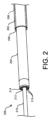
本開示の実施形態によるシステムの一部を形成する血管治療装置は、様々な形態をとりうる。一般に、本開示のいくつかの実施形態による血管治療装置は、導入器又は送達シースと、導入器シース内で平行移動可能に運ばれ、導入器シースから延在可能である治療カテーテルと、ガイドワイヤとを含む。より具体的な例として、図2を参照すると、血管治療装置200の例示的な実施形態が、示されている。血管治療装置200は、導入器又は送達シース202と、導入器シース202の管腔206内に平行移動可能に受容され、導入器シース202の遠位端208から延在可能であるレーザカテーテル204と、レーザカテーテル204の管腔212内に平行移動可能に受容され、それに沿ってレーザカテーテル204が治療空間に到達するように移動するガイドワイヤ210とを含む。レーザカテーテル204は、レーザ発生器(図示せず、例えば、フィリップス社から入手可能なスペクトラネティクス社のCVX-300エキシマレーザシステムなど)に結合し、そこからレーザエネルギを受け取り、対象の治療空間内の組織及び/又は他の物質(例えば、閉塞)を治療するようにレーザエネルギを放射する。レーザカテーテル204は、例えば、フィリップス社から入手可能な任意のスペクトラネティクス社のレーザカテーテルであってもよく、又は同様であってもよい。このようなレーザカテーテルは、例えば、ELCA(登録商標)及びTurbo Elite(商標)(各々は、それぞれ冠状動脈インターベンション又は末梢インターベンション、例えば、閉塞した動脈の再疎通、病変形態の変化、及びステント配置の容易化に使用される)、並びにSLSII(登録商標)及びGlideLight(登録商標)(外科的に移植されたリード除去に使用される)の商品名で入手可能なものを含む。レーザカテーテル204の作業(遠位)端214は、レーザ発生器から受け取られたレーザエネルギを放出し、治療空間内の標的組織及び/又は他の物質を切除する複数のレーザエミッタ216(例えば、光ファイバ)を有しうる。レーザカテーテル204の反対側の(近位)端部は、レーザカテーテル204をレーザ発生器に結合するための光ファイバカプラ(図示せず)を有しうる。これらの実施形態及び他の実施形態では、液体リザーバ内に運ばれ、処理空間に送達される液体は、生理食塩水であってもよい。液体リザーバは、導入シース202の管腔206と流体連通していてもよく、液体リザーバは、導入シース202の管腔206を介して、液体を治療空間に送達してもよい。
Vascular treatment devices that form part of systems according to embodiments of the present disclosure may take a variety of forms. In general, vascular treatment devices according to some embodiments of the present disclosure include an introducer or delivery sheath, a treatment catheter translatably carried within the introducer sheath and extendable from the introducer sheath, and a guidewire. including. As a more specific example, referring to FIG. 2, an exemplary embodiment of a
図3は、血管治療装置300の別の特定の例示的な実施形態を示す。血管治療装置300は、導入器又は送達シース302と、導入器シース302の管腔306内で平行移動可能に運ばれ、導入器シース302の遠位端308から延在可能なレーザカテーテル304と、レーザカテーテル304の管腔312内に平行移動可能に受容され、それに沿ってレーザカテーテル304が治療空間に到達するように移動するガイドワイヤ310とを含む。導入器シース302は、例えば、以下に列挙される特許文献に記載される導入器シース(「外側シース」とも称される)のいずれかであってもよく、又は同様であってもよい。レーザカテーテル304は、例えば、以下に列挙される特許文献に記載されるレーザカテーテルのいずれかであってもよく、又は同様であってもよい。
FIG. 3 depicts another specific exemplary embodiment of a
更に、導入器シース302、レーザカテーテル304、及びガイドワイヤ310は、一般に、(特に、血管閉塞を破壊するため、管腔内カルシウム沈着物を破壊するため、及び/又は内側カルシウム沈着物を破壊するための圧力波Pを生成するために造影剤溶液中にレーザエネルギを放出する)以下に列挙される特許文献に記載されるもののいずれかと同じ又は同様の方法で、治療空間内での治療を容易にするために使用され得る。これらの実施形態及び他の実施形態では、液体リザーバ内に運ばれ、治療空間に送達される液体は、以下に列挙される特許文献に記載されるように、造影剤又は造影剤溶液であってもよい。液体リザーバは、導入シース302の管腔306と流体連通していてもよく、液体リザーバは、導入シース302の管腔306を介して、液体を治療空間に送達してもよい。以下の特許文献は、それらが教示する全てのために及び全ての目的のために、参照によりその全体が本明細書に組み込まれる:2015年12月30日出願の米国特許出願第14/984,308号(発明の名称:Laser-Induced Pressure Wave Emitting Catheter Sheath)、2015年12月30日出願の米国特許出願第14/984,050号(発明の名称:Laser-Induced Fluid Filled Balloon Catheter)、2017年3月31日出願の米国特許出願第15/476,183号(発明の名称:Laser-Induced Fluid Filled Balloon Catheter Sheath)、2017年7月25日出願の米国特許出願第15/659,064号(発明の名称:Laser-Induced Pressure Wave Emitting Catheter Sheath)、及び2017年7月25日出願の米国特許出願第15/659,402号(発明の名称「Liquid Laser-Induced Pressure Wave Emitting Catheter Sheath」。
Additionally, the
簡潔に上述したように、本開示の実施形態による作動装置は、同時の治療空間内での血管治療装置の移動と、血管治療装置を介した治療空間への液体の送達とを容易にする。このような作動装置は、様々な形態をとりうる。特定の例として、図4を参照すると、作動装置400の例示的な実施形態が、示されている。作動装置400は、血管外科処置中にユーザによって把持されるように構成されたハウジング402を含む。ハウジング402は、第1の端部406において導入器シース404に結合する。導入器シース404は、カテーテル(他の場所に示される)を平行移動可能に担持し、カテーテルは、ハウジング402を通って、第2の端部410におけるポート408から外向きに延在する(例えば、カテーテルをレーザ発生器に結合することを容易にする)。ハウジング402は、移動アクチュエータ、より具体的にはハウジング402内のカテーテルに結合されたアーム412を平行移動可能に担持する。ハウジング402は、更に、液体を担持し、導入器シース404と流体連通する液体リザーバ、より具体的には注射器チャンバ414を担持する。注射器チャンバ414は、液体注入アクチュエータ、より具体的にはピストン416を平行移動可能に担持する。ピストン416及びアーム412は、両方とも、ユーザ入力部、より具体的には、ハウジング402の第2の端部410に向かって移動することによって作動されるトリガ418に結合する。したがって、トリガ418の作動は、同時の治療空間内の導入器シース404に対する(具体的には導入器シース404に対する近位方向の)カテーテルの移動と、導入器シース404を介した注射器チャンバ414から治療空間への液体の送達とを引き起こす。いくつかの実施形態では、作動装置400は、カテーテルの遠位端の位置を示すためのインジケータを含む。例えば、図示されるように、インジケータは、複数の境界422に対する、ハウジング402内のアーム412の位置を示す開口420を含んでもよい。いくつかの実施形態では、図示されるように、ハウジング402は、成形されてもよく、トリガ418及び注射器チャンバ414は、作動装置400が概してピストル様の外観を有するように配置されてもよい。
As briefly discussed above, actuation devices according to embodiments of the present disclosure facilitate simultaneous movement of a vascular treatment device within a treatment space and delivery of fluid through the vascular treatment device to the treatment space. Such actuators can take various forms. As a specific example, referring to FIG. 4, an exemplary embodiment of an
図5A及び5Bは、作動装置500の別の特定の例示的な実施形態を示す。作動装置500は、血管外科処置中にユーザによって把持されるように構成されたハウジング502を含む。ハウジング502は、第1の端部504において導入器シース(他の場所に示される)に結合する。導入器シースは、カテーテル(他の場所に示される)を平行移動可能に担持し、カテーテルは、(例えば、カテーテルをレーザ発生器に結合するのを容易にするために)ハウジング502を通って、第2の端部508におけるポートから外向きに延在する。ハウジング502は、移動アクチュエータ、より具体的にはハウジング502内でカテーテルに結合されるアーム(図示せず)を平行移動可能に担持する。ハウジング502は、更に、液体を担持し、導入器シースと流体連通している液体リザーバ、より具体的には注射器チャンバ510を担持する。注射器チャンバ510は、液体注入アクチュエータ、より具体的にはピストン512を平行移動可能に担持する。ピストン512及びアームは、両方とも、ユーザ入力部、より具体的にはハウジング502の第2の端部508に向かって移動することによって作動されるトリガ514に結合する。したがって、トリガ514の作動は、同時の治療空間内の導入器シースに対する(具体的には導入器シースに対する近位方向への)カテーテルの移動と、導入器シースを介した注射器チャンバ510から治療空間への液体の送達とを引き起こす。いくつかの実施形態では、図示されるように、ハウジング502は、作動装置500が概して細長い注射器様の外観を有するように成形されてもよい。
5A and 5B illustrate another specific exemplary embodiment of an
図6A及び6Bは、作動装置600の別の具体的な例示的実施形態を示す。作動装置600は、血管外科処置中にユーザによって把持されるように構成されたハウジング602を含む。ハウジング602は、第1の端部606において導入器シース604に結合する。導入器シース604は、カテーテル608を平行移動可能に担持し、カテーテル608は、(例えば、カテーテル608をレーザ発生器に結合するのを容易にするために)ハウジング602を通って、第2の端部612のポート610から外向きに延在する。ハウジング602は、ハウジング602内でカテーテル608に結合された移動アクチュエータ、より具体的にはアーム614(図6B参照)を平行移動可能に担持する。ハウジング602は、更に、液体を担持し、導入シース604と流体連通する液体リザーバ、より具体的には注射器チャンバ616を担持する。注射器チャンバ616は、液体注入アクチュエータ、より具体的にはピストン618を平行移動可能に担持する。ピストン618及びアーム614は、両方とも、ユーザ入力部、より具体的にはハウジング602の第2の端部612に向かって移動することによって作動されるトリガ620に結合する。したがって、トリガ620の作動は、同時の治療空間内の導入器シース604に対する(具体的には導入器シース604に対する近位方向の)カテーテル608の移動と、導入器シース604を介した注射器チャンバ616から治療空間への液体の送達とを引き起こす。いくつかの実施形態では、作動装置600がカテーテル608の遠位端の位置を示すためのインジケータを含む。例えば、図示されるように、インジケータは、複数の境界624及びインディシアム626に対するトリガ620の位置を示す開口622を含んでもよい。いくつかの実施形態では、図示されるように、ハウジング602は、作動装置600が概して細長い注射器様の外観を有するように成形されてもよい。
6A and 6B illustrate another specific exemplary embodiment of an
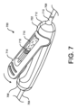
図7は、作動装置700の別の特定の例示的な実施形態を示す。作動装置700は、血管外科処置中にユーザによって把持されるように構成されたハウジング702を含む。ハウジング702は、第1の端部706において導入器シース704に結合する。導入器シース704は、カテーテル708を平行移動可能に担持し、カテーテル708は、(例えば、カテーテル708をレーザ発生器に結合するのを容易にするために)ハウジング702を通って、第2の端部712のポート710から外向きに延在する。ハウジング702は、ユーザ入力部、具体的には回転可能なレバー714を担持する。レバー714は、液体を担持し、導入シース704と流体連通している液体リザーバ、より具体的には注射器チャンバ716を担持する。注射器チャンバ716は、液体注入アクチュエータ、より具体的にはピストン718を平行移動可能に担持する。ハウジング702は、ハウジング702内のレバー714及びカテーテル708に結合される移動アクチュエータ、より具体的にはアーム(図示せず)を平行移動可能に担持する。したがって、レバー714の作動(すなわち、ハウジング702に対するレバー714の回転)は、同時の治療空間内の導入器シース704に対する(具体的には導入器シース704に対する近位方向の)カテーテル708の移動と、導入器シース704を介した注射器チャンバ716から治療空間への液体の送達とを引き起こす。より具体的には、作動装置700は、ピストン718がレバー714のそれぞれの作動に伴って一定距離だけレバー714のヒンジに向かって前進されるラチェット機構(図示せず)を含むことができる。この動作は、注射器チャンバ716内の液体を加圧し、それによって、液体をカテーテルに送達する。代わりに、ピストン718及び注射器チャンバ716の向きは、反転されることができ、ピストン718は、レバー714のヒンジ内に直接的に連結され、レバー714の各動作に対して押される又は引かれるように構成されることができる。別の代替として、ピストン718及び注射器チャンバ716は、ハウジング702内に配置されることができ、レバー714は、レバー714の回転を線形インクリメント運動に変換することによって(図示されないが、例えば、ラックアンドピニオンによって)、ピストン718に作用するように構成され、一方向にのみ前進するようにインデックス付けされることができる。更に別の代替として、チャンバ716は、チャンバ716に加えられた機械的圧力が液体を加圧するように、コンプライアント又は圧縮性であることができる。これらの実施形態及びその他の実施形態では、レバー714は、レバー714の回転時にピストン718を直線的に作動させるオフヒンジ連結アーム(図示せず)に結合する。それにより、ピストン718は、一方向圧力弁(図示せず)を介して、加圧流体(例えば、空気)を作動チャンバ(図示せず)に送達してもよい。これにより、作動チャンバは、拡張し、チャンバ716と係合し、チャンバ716に液体をカテーテルに送達させうる。
FIG. 7 shows another specific exemplary embodiment of an
いくつかの実施形態では、本明細書に記載されるシステム及び装置の特定の特徴は、カテーテルの平行移動速度に対して適切な流量で液体を送達することを容易にするように設計されてもよい。例えば、注射器チャンバ及びピストンの直径は、カテーテルの平行移動速度に対して適切な流量で液体を送達することを容易にするように選択され得る。 In some embodiments, certain features of the systems and devices described herein may be designed to facilitate delivering fluid at a flow rate appropriate to the translation speed of the catheter. good. For example, the diameters of the syringe chamber and piston can be selected to facilitate delivering liquid at a flow rate appropriate for the translation speed of the catheter.
上述の実施形態では、液体送達速度が、カテーテルの平行移動速度に対して固定される。他の実施形態では、液体送達速度が、カテーテルの平行移動速度に対して可変であってもよい。 In the embodiments described above, the liquid delivery rate is fixed relative to the translational rate of the catheter. In other embodiments, the liquid delivery rate may be variable relative to the catheter translation rate.
上述の実施形態では、カテーテルが、作動装置の作動時に近位に進む。他の実施形態では、カテーテルが、作動装置の作動時に遠位に進む。 In the embodiments described above, the catheter is advanced proximally upon actuation of the actuator. In other embodiments, the catheter is advanced distally upon actuation of the actuator.
上述の実施形態では、液体リザーバが、作動装置によって運ばれる。他の実施形態では、液体リザーバが、作動装置に液体を送達するが、作動装置によって運ばれないか、又は作動装置から外部に配置される。これらの実施形態及び他の実施形態において、作動装置は、液体リザーバへの結合を容易にするためのバルブを含んでもよく、液体リザーバは、加圧されることができる。 In the embodiments described above, the liquid reservoir is conveyed by the actuating device. In other embodiments, the liquid reservoir delivers liquid to the actuator, but is not carried by the actuator or is located external to the actuator. In these and other embodiments, the actuation device may include a valve to facilitate coupling to a liquid reservoir, and the liquid reservoir can be pressurized.
上述の実施形態では、システム及び装置が、レーザカテーテルを含み、及び/又はレーザカテーテルと共に使用される。他の実施形態では、本開示によるシステム及び装置が、他のタイプのカテーテルを含んでもよく、及び/又は他のタイプのカテーテルと一緒に使用されてもよい。例えば、そのようなカテーテルは、治療空間内の組織及び/又は他の物質を治療するために他のタイプの電磁エネルギ(例えば、無線周波数エネルギ)を放出することができ、又はそのようなカテーテルは、治療空間内の組織及び/又は他の物質を治療するために電磁エネルギを放出することなく動作することができる。より具体的な例として、いくつかのカテーテルは、治療空間内の組織及び/又は他の物質と物理的に係合し、治療する切断要素を含むことができる。いくつかの実施形態では、本開示によるシステム及び装置が、回転式アテローム切除カテーテルを含んでもよく、かつ/又は回転式アテローム切除カテーテルと一緒に使用されてもよい。いくつかの実施形態では、本開示によるシステム及び装置が、軌道アテローム切除カテーテルを含んでもよく、かつ/又は軌道アテローム切除カテーテルと共に使用されてもよい。いくつかの実施形態では、本開示によるシステム及び装置が、血管内撮像カテーテルを含んでもよく、かつ/又は血管内撮像カテーテルと一緒に使用されてもよい。いくつかの実施形態では、本開示によるシステム及び装置は、カテーテル先端又は本体の一部又は全てがカテーテル及び/又は導入器もしくは送達シースの他の部分に対して回転することができるカテーテルを含んでもよく、かつ/又はカテーテルと一緒に使用されてもよく、これらの実施形態では、液体は、カテーテルの回転を容易にする潤滑剤であってもよい。 In the embodiments described above, the systems and devices include and/or are used with laser catheters. In other embodiments, systems and devices according to the present disclosure may include and/or be used with other types of catheters. For example, such catheters can emit other types of electromagnetic energy (e.g., radio frequency energy) to treat tissue and/or other materials within the treatment space, or such catheters can , can operate without emitting electromagnetic energy to treat tissue and/or other materials within the treatment space. As a more specific example, some catheters may include cutting elements that physically engage and treat tissue and/or other materials within the treatment space. In some embodiments, systems and devices according to the present disclosure may include and/or be used with a rotating atherectomy catheter. In some embodiments, systems and devices according to the present disclosure may include and/or be used with an orbital atherectomy catheter. In some embodiments, systems and devices according to the present disclosure may include and/or be used with intravascular imaging catheters. In some embodiments, systems and devices according to the present disclosure may include a catheter in which part or all of the catheter tip or body can rotate relative to the catheter and/or other parts of the introducer or delivery sheath. In these embodiments, the liquid may be a lubricant to facilitate rotation of the catheter.
いくつかの実施形態では、本開示の実施形態によるシステム及び装置の移動アクチュエータが、変速器又は減速器を含んでもよい。 In some embodiments, movement actuators of systems and devices according to embodiments of the present disclosure may include a transmission or a speed reducer.
いくつかの実施形態では、本開示の実施形態によるシステム及び装置のユーザ入力部は、他の形態をとってもよい。例えば、ユーザ入力部は、作動装置のハウジングによって回転可能に担持されるホイールであってもよく、ホイールは、移動アクチュエータ及び液体注入アクチュエータを同時に作動させるために、ハウジングに対して回転可能に作動可能であってもよい。 In some embodiments, user input for systems and devices according to embodiments of the present disclosure may take other forms. For example, the user input may be a wheel rotatably carried by the housing of the actuator, the wheel being rotatably actuatable relative to the housing to simultaneously actuate the movement actuator and the liquid injection actuator. It may be.
いくつかの実施形態では、本開示によるシステム及び装置は、ユーザ入力部の作動が、対象からの流体/物質の吸引を容易にする負圧をチャンバ内に生成するように構成されたチャンバ(図示せず)を含んでもよい。 In some embodiments, systems and devices according to the present disclosure include a chamber (see FIG. (not shown) may also be included.
いくつかの実施形態では、本開示によるシステム、装置及び方法は、2018年9月6日出願の「Valved Handle Assembly Having a Movable Ring」と題された米国特許出願第62/728,004号に記載されているような、封止制御装置及び方法を組み込むことができ、この出願はそれが教示する全てに対して及び全ての目的のために、その全体が参照によって本明細書に組み込まれる。 In some embodiments, systems, apparatus and methods according to the present disclosure are described in U.S. patent application Ser. This application is incorporated herein by reference in its entirety for all its teachings and for all purposes.
上述の実施形態では、本開示によるシステム及び装置は、一般に機械的である。他の実施形態では、本開示によるシステム及び装置は、電気機械的であってもよい。より具体的には、本開示によるシステム及び装置は、互いに電気的に結合される又は非機械的に動作可能に結合される1つ又は複数の構成要素を含んでもよい。 In the embodiments described above, systems and devices according to the present disclosure are generally mechanical. In other embodiments, systems and devices according to the present disclosure may be electromechanical. More specifically, systems and devices according to the present disclosure may include one or more components that are electrically coupled or non-mechanically operably coupled to each other.
いくつかの実施形態では、本開示によるシステムは、図1に示されるシステム100などの「使用準備完了」構成で(すなわち、ユーザの部品の組立てを必要とせずに)ユーザ(例えば、外科医)に提供されることができる。いくつかの実施形態では、本開示によるシステムは、例えば、ユーザが特定の対象及び/又は処置のために適切な血管治療装置に対して作動装置を結合することを可能にするために、分解された構成でユーザに提供されることができる。
In some embodiments, a system according to the present disclosure can be delivered to a user (e.g., a surgeon) in a "ready-to-use" configuration (i.e., without requiring assembly of the user's parts), such as the
前述の議論は、例示及び説明の目的で提示されている。上記は、本開示を本明細書に開示される形態に限定することを意図するものではない。前述の「発明の概要」では、例えば、本開示の様々な特徴は、開示を合理化する目的で、1つ又は複数の態様、実施形態、及び/又は構成で一緒にグループ化される。本開示の態様、実施形態、及び/又は構成の特徴は、上記で論じられたもの以外の代替の態様、実施形態、及び/又は構成で組み合わされてもよい。この開示の方法は、請求項が、各請求項に明示的に記載されているよりも多くの特徴を必要とするという意図を反映するものとして解釈されるべきではない。むしろ、以下の請求項が反映するように、発明の態様は、単一の先行する開示された態様、実施形態、及び/又は構成の全てより少ない特徴にある。したがって、以下の請求項は、本発明の詳細な説明に組み込まれ、各請求項は、それ自体が本開示の別個の好ましい実施形態として存在する。 The foregoing discussion has been presented for purposes of illustration and explanation. The above is not intended to limit the disclosure to the form disclosed herein. In the foregoing Summary of the Invention, for example, various features of the disclosure are grouped together in one or more aspects, embodiments, and/or configurations for the purpose of streamlining the disclosure. Features of aspects, embodiments, and/or configurations of the present disclosure may be combined in alternative aspects, embodiments, and/or configurations other than those discussed above. This method of disclosure is not to be interpreted as reflecting an intention that the claims require more features than are expressly recited in each claim. Rather, as the following claims reflect, inventive aspects lie in less than all features of a single preceding disclosed aspect, embodiment, and/or arrangement. Thus, the following claims are hereby incorporated into the Detailed Description of the Invention, with each claim standing on its own as a separate preferred embodiment of this disclosure.
更に、説明は、1つ又は複数の態様、実施形態、及び/又は構成、並びに特定の変形及び修正の説明を含んでいるが、他の変形、組み合わせ、及び修正は、例えば、本開示を理解した後に、当業者の技能及び知識の範囲内であり得る、本開示の範囲内である。任意の特許性のある主題を公に専用にすることを意図することなく、本明細書に開示されているか否かにかかわらず、請求されたものに対する代替の、互換性のある及び/又は同等の構造、機能、範囲、又はステップを含む、代替の態様、実施形態、及び/又は構成を許可される程度まで含む権利を取得することが意図される。 Additionally, while the description includes a description of one or more aspects, embodiments, and/or configurations, as well as certain variations and modifications, other variations, combinations, and modifications may occur, e.g. is within the scope of this disclosure, which may be within the skill and knowledge of one of ordinary skill in the art. Without intending to dedicate any patentable subject matter to the public, any alternative, compatible and/or equivalent to that claimed, whether or not disclosed herein. It is intended that the right be reserved to the extent permitted, to include alternative aspects, embodiments, and/or configurations, including the structure, functionality, scope, or steps of.
Claims (16)
前記血管治療装置に動作可能に結合された作動装置であって、
前記血管治療装置に動作可能に結合された移動アクチュエータ、
前記導入器シースと流体連通する液体リザーバ、
前記液体リザーバに動作可能に結合された液体注入アクチュエータ、及び
前記移動アクチュエータ及び前記液体注入アクチュエータを同時に作動させるように作動可能であるユーザ入力部であって、前記ユーザ入力部は、前記ユーザ入力部が移動することによって、前記移動アクチュエータが前記血管治療装置の少なくとも一部を前記治療空間内で近位方向に移動させ、前記液体注入アクチュエータが前記液体リザーバから前記導入器シースを介して前記治療空間まで遠位方向に前記液体を送達するように、前記移動アクチュエータ及び前記液体注入アクチュエータに結合されるユーザ入力部、
を有する作動装置と、
を有する、血管治療システム。 a vascular treatment device configured to be placed within a treatment space of a subject and having an introducer sheath having an inner lumen ;
an actuation device operably coupled to the vascular treatment device, the actuation device comprising:
a movement actuator operably coupled to the vascular treatment device;
a liquid reservoir in fluid communication with the introducer sheath ;
a liquid injection actuator operably coupled to the liquid reservoir ; and a user input operable to simultaneously actuate the movement actuator and the liquid injection actuator , wherein the user input movement of the vascular treatment device causes the movement actuator to move at least a portion of the vascular treatment device proximally within the treatment space, and the liquid injection actuator moves the vascular treatment device from the liquid reservoir through the introducer sheath to cause the treatment a user input coupled to the movement actuator and the liquid injection actuator to deliver the liquid distally into a space ;
an actuating device having;
A vascular treatment system with
内側管腔を有する導入器シースと、
前記導入器シースの前記内側管腔内で平行移動可能に運ばれるカテーテルと、
を有する、請求項1に記載の血管治療システム。 The vascular treatment device includes:
an introducer sheath having an inner lumen;
a catheter translatably carried within the inner lumen of the introducer sheath;
The vascular treatment system according to claim 1, comprising:
内側管腔を有する導入器シースを有する血管治療装置に動作可能に結合されるように構成された移動アクチュエータと、
前記導入器シースと流体連通する液体リザーバと、
前記液体リザーバに動作可能に結合された液体注入アクチュエータと、
前記移動アクチュエータ及び前記液体注入アクチュエータを同時に作動させるように作動可能であるユーザ入力部であって、前記ユーザ入力部は、前記ユーザ入力部が移動することによって、前記移動アクチュエータが対象の治療空間内で近位方向に前記血管治療装置の少なくとも一部を移動させ、前記液体注入アクチュエータが前記液体リザーバから前記導入器シースを介して前記治療空間まで遠位方向に前記液体を送達するように、前記移動アクチュエータ及び前記液体注入アクチュエータに結合されるユーザ入力部と、
を有する作動装置。 An actuation device for a vascular treatment system, the actuation device comprising:
a movement actuator configured to be operably coupled to a vascular treatment device having an introducer sheath having an inner lumen ;
a liquid reservoir in fluid communication with the introducer sheath ;
a liquid injection actuator operably coupled to the liquid reservoir;
a user input operable to simultaneously actuate the movement actuator and the liquid injection actuator , wherein movement of the user input causes the movement actuator to move within the target treatment space; moving at least a portion of the vascular treatment device in a proximal direction such that the liquid injection actuator delivers the liquid distally from the liquid reservoir through the introducer sheath to the treatment space; a user input coupled to a movement actuator and the liquid injection actuator ;
an actuating device having a
前記血管治療装置に動作可能に結合された作動装置であって、
前記血管治療装置に動作可能に結合された移動アクチュエータ、
前記導入器シースと流体連通する液体リザーバに動作可能に結合するように構成された液体注入アクチュエータ、 及び
前記移動アクチュエータ及び前記液体注入アクチュエータを同時に作動させるように作動可能であるユーザ入力部であって、前記ユーザ入力部は、前記ユーザ入力部が移動することによって、前記移動アクチュエータが前記血管治療装置の少なくとも一部を前記治療空間内で近位方向に移動させ、前記液体注入アクチュエータが前記液体リザーバから前記導入器シースを介して前記治療空間まで遠位方向に液体を送達するように、前記移動アクチュエータ及び前記液体注入アクチュエータに結合されるユーザ入力部、
を有する作動装置と、
を有する、血管治療システム。 a vascular treatment device configured to be placed within a treatment space of a subject and having an introducer sheath having an inner lumen ;
an actuation device operably coupled to the vascular treatment device, the actuation device comprising:
a movement actuator operably coupled to the vascular treatment device;
a liquid injection actuator configured to operably couple to a liquid reservoir in fluid communication with the introducer sheath ; and a user input operable to simultaneously actuate the movement actuator and the liquid injection actuator. The user input unit is configured such that movement of the user input unit causes the movement actuator to move at least a portion of the vascular treatment device in a proximal direction within the treatment space, and the liquid injection actuator causes the liquid injection actuator to move at least a portion of the vascular treatment device in a proximal direction within the treatment space. a user input coupled to the movement actuator and the liquid injection actuator to deliver liquid distally from a reservoir through the introducer sheath to the treatment space;
an actuating device having;
A vascular treatment system with
内側管腔を有する導入器シースを有する血管治療装置に動作可能に結合されるように構成された移動アクチュエータと、
前記導入器シースと流体連通する液体リザーバに動作可能に結合するように構成された液体注入アクチュエータと、
前記移動アクチュエータ及び前記液体注入アクチュエータを同時に作動させるように作動可能であるユーザ入力部であって、前記ユーザ入力部は、前記ユーザ入力部が移動することによって、前記移動アクチュエータが対象の治療空間内で近位方向に前記血管治療装置の少なくとも一部を移動させ、前記液体注入アクチュエータが前記液体リザーバから前記導入器シースを介して前記治療空間まで遠位方向に液体を送達するように、前記移動アクチュエータ及び前記液体注入アクチュエータに結合されるユーザ入力部と、
を有する作動装置。 An actuation device for a vascular treatment system, the actuation device comprising:
a movement actuator configured to be operably coupled to a vascular treatment device having an introducer sheath having an inner lumen ;
a liquid injection actuator configured to operably couple to a liquid reservoir in fluid communication with the introducer sheath ;
a user input operable to simultaneously actuate the movement actuator and the liquid injection actuator , wherein movement of the user input causes the movement actuator to move within the target treatment space; moving at least a portion of the vascular treatment device in a proximal direction, such that the liquid injection actuator delivers liquid distally from the liquid reservoir through the introducer sheath to the treatment space. an actuator and a user input coupled to the liquid injection actuator ;
an actuating device having a
Applications Claiming Priority (3)
| Application Number | Priority Date | Filing Date | Title |
|---|---|---|---|
| US201862774274P | 2018-12-02 | 2018-12-02 | |
| US62/774,274 | 2018-12-02 | ||
| PCT/EP2019/082772 WO2020114861A1 (en) | 2018-12-02 | 2019-11-27 | Devices, systems, and methods for simultaneous liquid infusion and catheter motion |
Publications (3)
| Publication Number | Publication Date |
|---|---|
| JP2022510230A JP2022510230A (en) | 2022-01-26 |
| JPWO2020114861A5 JPWO2020114861A5 (en) | 2022-11-16 |
| JP7428711B2 true JP7428711B2 (en) | 2024-02-06 |
Family
ID=68762714
Family Applications (1)
| Application Number | Title | Priority Date | Filing Date |
|---|---|---|---|
| JP2021530240A Active JP7428711B2 (en) | 2018-12-02 | 2019-11-27 | Devices, systems, and methods for simultaneous fluid injection and catheter operation |
Country Status (5)
| Country | Link |
|---|---|
| US (1) | US20220031393A1 (en) |
| EP (1) | EP3886746A1 (en) |
| JP (1) | JP7428711B2 (en) |
| CN (1) | CN113260330A (en) |
| WO (1) | WO2020114861A1 (en) |
Citations (1)
| Publication number | Priority date | Publication date | Assignee | Title |
|---|---|---|---|---|
| JP2009542422A (en) | 2006-07-07 | 2009-12-03 | カイフォン・ソシエテ・ア・レスポンサビリテ・リミテ | Medical device with expansion mechanism |
Family Cites Families (6)
| Publication number | Priority date | Publication date | Assignee | Title |
|---|---|---|---|---|
| US4529399A (en) * | 1983-05-03 | 1985-07-16 | Catheter Technology Corporation | Method and apparatus for placing a catheter |
| US6197001B1 (en) * | 1996-09-27 | 2001-03-06 | Becton Dickinson And Company | Vascular access device |
| WO2011008922A2 (en) * | 2009-07-16 | 2011-01-20 | Hansen Medical, Inc. | Endoscopic robotic catheter system |
| WO2014145354A1 (en) * | 2013-03-15 | 2014-09-18 | 410 Medical Innovations Llc | Apparatus and method for rapid intraosseous fluid infusion |
| US11246659B2 (en) * | 2014-08-25 | 2022-02-15 | The Spectranetics Corporation | Liquid laser-induced pressure wave emitting catheter sheath |
| WO2017192912A1 (en) * | 2016-05-04 | 2017-11-09 | Renalpro Medical, Inc. | Devices and methods for treating acute kidney injury |
-
2019
- 2019-11-27 WO PCT/EP2019/082772 patent/WO2020114861A1/en active Application Filing
- 2019-11-27 US US17/298,780 patent/US20220031393A1/en active Pending
- 2019-11-27 CN CN201980087702.9A patent/CN113260330A/en active Pending
- 2019-11-27 JP JP2021530240A patent/JP7428711B2/en active Active
- 2019-11-27 EP EP19813272.2A patent/EP3886746A1/en active Pending
Patent Citations (1)
| Publication number | Priority date | Publication date | Assignee | Title |
|---|---|---|---|---|
| JP2009542422A (en) | 2006-07-07 | 2009-12-03 | カイフォン・ソシエテ・ア・レスポンサビリテ・リミテ | Medical device with expansion mechanism |
Also Published As
| Publication number | Publication date |
|---|---|
| US20220031393A1 (en) | 2022-02-03 |
| WO2020114861A1 (en) | 2020-06-11 |
| JP2022510230A (en) | 2022-01-26 |
| EP3886746A1 (en) | 2021-10-06 |
| CN113260330A (en) | 2021-08-13 |
Similar Documents
| Publication | Publication Date | Title |
|---|---|---|
| US5370609A (en) | Thrombectomy device | |
| JP6968146B2 (en) | Catheter sheath that radiates liquid laser-induced pressure waves | |
| US7485127B2 (en) | Tubular torque transmitting system for medical device | |
| US5496267A (en) | Asymmetric water jet atherectomy | |
| US20200121356A1 (en) | Systems and methods for manipulating medical devices | |
| EP3434311B1 (en) | Drug delivery via mechanical vibration balloon | |
| US6135977A (en) | Rheolytic catheter | |
| EP3054856B1 (en) | Device for synchronized injection and aspiration | |
| US20040243162A1 (en) | Interventional catheter assemblies and control systems | |
| EP0489496B1 (en) | Water jet atherectomy device | |
| US20150342681A1 (en) | Segmented balloon laser ablation catheter | |
| US20170086860A1 (en) | Support catheter and guidewire kit for crossing a vascular occlusion | |
| WO2004080507A2 (en) | Interventional catheters assemblies and control systems | |
| CN113038898A (en) | Treatment mode selection system and laser catheter system comprising a treatment mode selection system | |
| CN114601558A (en) | Laser ablation catheter with variable optical fiber spiral angle | |
| JP7428711B2 (en) | Devices, systems, and methods for simultaneous fluid injection and catheter operation | |
| US20230363787A1 (en) | Cutting balloon catheter with concealed blades | |
| JP6412105B2 (en) | Steering control mechanism for catheter | |
| EP3362122B1 (en) | System for delivery of a therapeutic agent through a catheter | |
| CN114423362A (en) | Atherectomy device comprising an axially oscillating cutting element | |
| CN114222536A (en) | Atherectomy devices including multiple distal cutting features | |
| CN115998377A (en) | Excision device | |
| WO2021122253A1 (en) | Atherectomy devices including sealed drive shafts | |
| CN211796844U (en) | Intelligent device with laser thrombus crushing function | |
| US20230060914A1 (en) | Apparatus including endovascular device connected to a powered syringe assembly |
Legal Events
| Date | Code | Title | Description |
|---|---|---|---|
| A521 | Request for written amendment filed |
Free format text: JAPANESE INTERMEDIATE CODE: A523 Effective date: 20221107 |
|
| A621 | Written request for application examination |
Free format text: JAPANESE INTERMEDIATE CODE: A621 Effective date: 20221107 |
|
| A131 | Notification of reasons for refusal |
Free format text: JAPANESE INTERMEDIATE CODE: A131 Effective date: 20230817 |
|
| A977 | Report on retrieval |
Free format text: JAPANESE INTERMEDIATE CODE: A971007 Effective date: 20230823 |
|
| A521 | Request for written amendment filed |
Free format text: JAPANESE INTERMEDIATE CODE: A523 Effective date: 20231114 |
|
| TRDD | Decision of grant or rejection written | ||
| A01 | Written decision to grant a patent or to grant a registration (utility model) |
Free format text: JAPANESE INTERMEDIATE CODE: A01 Effective date: 20240105 |
|
| A61 | First payment of annual fees (during grant procedure) |
Free format text: JAPANESE INTERMEDIATE CODE: A61 Effective date: 20240125 |
|
| R150 | Certificate of patent or registration of utility model |
Ref document number: 7428711 Country of ref document: JP Free format text: JAPANESE INTERMEDIATE CODE: R150 |