JP2009539425A - Medical electrical lead with deployable securing mechanism - Google Patents
Medical electrical lead with deployable securing mechanism Download PDFInfo
- Publication number
- JP2009539425A JP2009539425A JP2009513360A JP2009513360A JP2009539425A JP 2009539425 A JP2009539425 A JP 2009539425A JP 2009513360 A JP2009513360 A JP 2009513360A JP 2009513360 A JP2009513360 A JP 2009513360A JP 2009539425 A JP2009539425 A JP 2009539425A
- Authority
- JP
- Japan
- Prior art keywords
- lead
- region
- tendon
- distal
- deflectable
- Prior art date
- Legal status (The legal status is an assumption and is not a legal conclusion. Google has not performed a legal analysis and makes no representation as to the accuracy of the status listed.)
- Pending
Links
- 230000007246 mechanism Effects 0.000 title abstract description 49
- 210000002435 tendon Anatomy 0.000 claims abstract description 135
- 230000002526 effect on cardiovascular system Effects 0.000 claims abstract description 23
- 239000000463 material Substances 0.000 claims description 21
- 229920002635 polyurethane Polymers 0.000 claims description 4
- 239000004814 polyurethane Substances 0.000 claims description 4
- 230000007704 transition Effects 0.000 claims description 4
- 229920001296 polysiloxane Polymers 0.000 claims description 3
- 239000007779 soft material Substances 0.000 claims 2
- 230000008859 change Effects 0.000 abstract description 7
- 230000007774 longterm Effects 0.000 abstract description 7
- 230000001154 acute effect Effects 0.000 abstract description 5
- 238000003780 insertion Methods 0.000 description 17
- 230000037431 insertion Effects 0.000 description 17
- 210000003748 coronary sinus Anatomy 0.000 description 13
- 238000000034 method Methods 0.000 description 13
- 230000033001 locomotion Effects 0.000 description 11
- 230000036961 partial effect Effects 0.000 description 10
- 230000002792 vascular Effects 0.000 description 9
- 238000004873 anchoring Methods 0.000 description 8
- 230000000747 cardiac effect Effects 0.000 description 8
- 229920000642 polymer Polymers 0.000 description 8
- 238000000576 coating method Methods 0.000 description 7
- 239000004020 conductor Substances 0.000 description 7
- 210000002216 heart Anatomy 0.000 description 7
- 230000009471 action Effects 0.000 description 5
- 239000011248 coating agent Substances 0.000 description 5
- 210000005166 vasculature Anatomy 0.000 description 5
- 229910052751 metal Inorganic materials 0.000 description 4
- 239000002184 metal Substances 0.000 description 4
- 238000012986 modification Methods 0.000 description 4
- 230000004048 modification Effects 0.000 description 4
- HLXZNVUGXRDIFK-UHFFFAOYSA-N nickel titanium Chemical group [Ti].[Ti].[Ti].[Ti].[Ti].[Ti].[Ti].[Ti].[Ti].[Ti].[Ti].[Ni].[Ni].[Ni].[Ni].[Ni].[Ni].[Ni].[Ni].[Ni].[Ni].[Ni].[Ni].[Ni].[Ni] HLXZNVUGXRDIFK-UHFFFAOYSA-N 0.000 description 4
- 229910001000 nickel titanium Inorganic materials 0.000 description 4
- 239000004810 polytetrafluoroethylene Substances 0.000 description 4
- 229920001343 polytetrafluoroethylene Polymers 0.000 description 4
- 230000003014 reinforcing effect Effects 0.000 description 4
- 210000005245 right atrium Anatomy 0.000 description 4
- 210000003462 vein Anatomy 0.000 description 4
- 150000002739 metals Chemical class 0.000 description 3
- 239000010935 stainless steel Substances 0.000 description 3
- 229910001220 stainless steel Inorganic materials 0.000 description 3
- 239000004696 Poly ether ether ketone Substances 0.000 description 2
- 229910045601 alloy Inorganic materials 0.000 description 2
- 239000000956 alloy Substances 0.000 description 2
- 210000004351 coronary vessel Anatomy 0.000 description 2
- 238000000605 extraction Methods 0.000 description 2
- 230000001965 increasing effect Effects 0.000 description 2
- 230000002452 interceptive effect Effects 0.000 description 2
- 210000005240 left ventricle Anatomy 0.000 description 2
- 230000014759 maintenance of location Effects 0.000 description 2
- 238000007726 management method Methods 0.000 description 2
- 229920002530 polyetherether ketone Polymers 0.000 description 2
- 230000000452 restraining effect Effects 0.000 description 2
- 230000033764 rhythmic process Effects 0.000 description 2
- 210000005241 right ventricle Anatomy 0.000 description 2
- 238000007788 roughening Methods 0.000 description 2
- 230000002269 spontaneous effect Effects 0.000 description 2
- 206010016654 Fibrosis Diseases 0.000 description 1
- 238000007792 addition Methods 0.000 description 1
- 239000000853 adhesive Substances 0.000 description 1
- 230000001070 adhesive effect Effects 0.000 description 1
- 238000013459 approach Methods 0.000 description 1
- JUPQTSLXMOCDHR-UHFFFAOYSA-N benzene-1,4-diol;bis(4-fluorophenyl)methanone Chemical compound OC1=CC=C(O)C=C1.C1=CC(F)=CC=C1C(=O)C1=CC=C(F)C=C1 JUPQTSLXMOCDHR-UHFFFAOYSA-N 0.000 description 1
- 210000004204 blood vessel Anatomy 0.000 description 1
- 239000002131 composite material Substances 0.000 description 1
- 230000008602 contraction Effects 0.000 description 1
- 230000008878 coupling Effects 0.000 description 1
- 238000010168 coupling process Methods 0.000 description 1
- 238000005859 coupling reaction Methods 0.000 description 1
- 238000013461 design Methods 0.000 description 1
- 238000010586 diagram Methods 0.000 description 1
- 238000012377 drug delivery Methods 0.000 description 1
- 230000000694 effects Effects 0.000 description 1
- 210000001174 endocardium Anatomy 0.000 description 1
- 230000002708 enhancing effect Effects 0.000 description 1
- 230000004761 fibrosis Effects 0.000 description 1
- 230000006870 function Effects 0.000 description 1
- 238000013152 interventional procedure Methods 0.000 description 1
- 230000001788 irregular Effects 0.000 description 1
- 210000005246 left atrium Anatomy 0.000 description 1
- 230000000670 limiting effect Effects 0.000 description 1
- 230000013011 mating Effects 0.000 description 1
- 210000004165 myocardium Anatomy 0.000 description 1
- 229920006254 polymer film Polymers 0.000 description 1
- 230000002035 prolonged effect Effects 0.000 description 1
- 230000001737 promoting effect Effects 0.000 description 1
- 230000002787 reinforcement Effects 0.000 description 1
- 230000004044 response Effects 0.000 description 1
- 230000003068 static effect Effects 0.000 description 1
- 230000000638 stimulation Effects 0.000 description 1
- 238000004381 surface treatment Methods 0.000 description 1
- 239000003356 suture material Substances 0.000 description 1
Images


Classifications
-
- A—HUMAN NECESSITIES
- A61—MEDICAL OR VETERINARY SCIENCE; HYGIENE
- A61N—ELECTROTHERAPY; MAGNETOTHERAPY; RADIATION THERAPY; ULTRASOUND THERAPY
- A61N1/00—Electrotherapy; Circuits therefor
- A61N1/02—Details
- A61N1/04—Electrodes
- A61N1/05—Electrodes for implantation or insertion into the body, e.g. heart electrode
- A61N1/056—Transvascular endocardial electrode systems
- A61N1/057—Anchoring means; Means for fixing the head inside the heart
- A61N1/0573—Anchoring means; Means for fixing the head inside the heart chacterised by means penetrating the heart tissue, e.g. helix needle or hook
-
- A—HUMAN NECESSITIES
- A61—MEDICAL OR VETERINARY SCIENCE; HYGIENE
- A61B—DIAGNOSIS; SURGERY; IDENTIFICATION
- A61B18/00—Surgical instruments, devices or methods for transferring non-mechanical forms of energy to or from the body
- A61B18/04—Surgical instruments, devices or methods for transferring non-mechanical forms of energy to or from the body by heating
- A61B18/12—Surgical instruments, devices or methods for transferring non-mechanical forms of energy to or from the body by heating by passing a current through the tissue to be heated, e.g. high-frequency current
- A61B18/14—Probes or electrodes therefor
- A61B18/1492—Probes or electrodes therefor having a flexible, catheter-like structure, e.g. for heart ablation
-
- A—HUMAN NECESSITIES
- A61—MEDICAL OR VETERINARY SCIENCE; HYGIENE
- A61N—ELECTROTHERAPY; MAGNETOTHERAPY; RADIATION THERAPY; ULTRASOUND THERAPY
- A61N1/00—Electrotherapy; Circuits therefor
- A61N1/02—Details
- A61N1/04—Electrodes
- A61N1/05—Electrodes for implantation or insertion into the body, e.g. heart electrode
- A61N1/056—Transvascular endocardial electrode systems
- A61N2001/0585—Coronary sinus electrodes
Abstract
心臓血管内に少なくとも部分的に差し込まれるように構成された医療用電気リードは、非展開形態から、固定機構が心臓血管の内面を係合させるように構成される展開形態に変化するように操作可能である固定機構を含む。テンドンは、リードの内腔内に配置され、かつ固定機構に操作可能に接続され、かつリードの急性及び/又は長期固定のために固定機構を、非展開形態から、展開形態に変化させるように構成される。固定機構は、展開形態でリード本体の表面が心臓血管の内面を係合させるようにするリードの偏向可能領域を含む。 A medical electrical lead configured to be inserted at least partially into the cardiovascular is manipulated to change from an undeployed configuration to a deployed configuration in which the fixation mechanism is configured to engage the inner surface of the cardiovascular vessel. Includes a locking mechanism that is possible. The tendon is disposed within the lumen of the lead and is operably connected to the fixation mechanism and is adapted to change the fixation mechanism from an undeployed configuration to a deployed configuration for acute and / or long-term fixation of the lead. Composed. The fixation mechanism includes a deflectable region of the lead that causes the surface of the lead body to engage the inner surface of the cardiovascular in the deployed configuration.
Description
関連出願の相互参照
本出願は、Brian D.Soltis,et al.による2006年6月2日に出願された、「MEDICAL ELECTRICAL LEAD WITH EXPANDABLE FIXATION FEATURES」と題する同時係属米国特許出願第11/422000号と関連する。上記出願は、あらゆる目的のために参照によって本明細書に組み込まれる。
Cross-reference of related applications Soltis, et al. In conjunction with copending US patent application Ser. No. 11/422000, filed Jun. 2, 2006, entitled “MEDICAL ELECTRICAL LEAD WITH EXPANDABLE FIXATION FEATURES”. The above application is incorporated herein by reference for all purposes.
本発明は、医療用電気リードの固定装置及び方法に関する。具体的には、本発明は、患者の血管系、及び特には冠血管系内に医療用電気リードの一部を急性及び長期的に固定する、展開可能な装置及び方法を対象とする。 The present invention relates to a medical electrical lead fixing device and method. Specifically, the present invention is directed to deployable devices and methods for acute and long-term fixation of a portion of a medical electrical lead within a patient's vasculature, and particularly the coronary vasculature.
電気刺激を用いて心臓の不整収縮を治療する埋め込み型医療装置が知られている。代表的な埋め込み型装置は除細動器やペースメーカーである。除細動器やペースメーカー用の様々なタイプの電気リードが提案されてきており、それらの多くは経静脈的に配置される。そのようなリードは、静脈アクセス部位で患者の血管系に導入され、静脈を通って、リードの電極が埋め込まれる部位まで進むか、別の方法として標的の冠状動脈組織に接触する。経静脈的に配置されたリードの電極は、右心房又は右心室の心内膜(心臓の内側を裏打ちする組織)に、あるいは冠状静脈系の分岐血管に差し込むことができる。特に、リード電極は、心臓の左側(即ち、左心室)を感知及び/又は刺激するため、冠状静脈洞又はその分岐血管に差し込まれる。 Implantable medical devices are known that treat cardiac irregular contractions using electrical stimulation. Typical implantable devices are defibrillators and pacemakers. Various types of electrical leads for defibrillators and pacemakers have been proposed, many of which are placed intravenously. Such a lead is introduced into the patient's vasculature at the venous access site and travels through the vein to the site where the lead electrode is implanted, or alternatively contacts the target coronary artery tissue. The electrodes of the transvenously placed lead can be inserted into the endocardium of the right atrium or right ventricle (tissue lining the inside of the heart) or into a branch vessel of the coronary venous system. In particular, the lead electrode is inserted into the coronary sinus or its branch vessel to sense and / or stimulate the left side of the heart (ie, the left ventricle).
所望の差し込み部位での前述のタイプのリードの固定を容易にするために、種々の技術が使用された。冠静脈系内に部分的に差し込まれるリードに関して、固定技術は、差し込み部位へリードを送ることを妨げることなく、リードを所望の差し込み位置に急性的にも、長期的にも固着するために十分な固定を行うべきである。 Various techniques have been used to facilitate securing the aforementioned types of leads at the desired insertion site. For leads that are partially inserted into the coronary venous system, fixation techniques are sufficient to secure the lead to the desired insertion location, both acutely and long term, without interfering with sending the lead to the insertion site. Should be fixed.
従って、当該技術分野において、リードの搬送に干渉せず、かつ急性及び/又は長期固定を行うために搬送後に展開できる、心臓リードを冠血管系内に固定する装置及び方法が必要である。 Accordingly, there is a need in the art for an apparatus and method for securing a cardiac lead within the coronary vasculature that does not interfere with lead delivery and can be deployed after delivery for acute and / or long-term fixation.
本発明は、一実施態様において、パルス発生器と、パルス発生器に結合された近位端を有するリードとを含む差し込み型システムである。リードは、心臓血管内に部分的に差し込まれるように構成され、かつ近位領域及び遠位領域を備えた細長いリード本体を含み、遠位領域は、本体上に電極を、本体上に偏向位置を有し、かつ組織係合外面を有する偏向可能領域を含む。リードは、本体内に少なくとも部分的に配置され、かつ偏向可能領域に遠位の第1取付位置で張力を受けて本体に取り付けられたテンドンを更に含む。テンドン内の張力は、偏向可能領域を偏向形状に維持し、その中で組織係合外面は、心臓血管の内面を摩擦によって係合させることができる。 The present invention, in one embodiment, is a plug-in system that includes a pulse generator and a lead having a proximal end coupled to the pulse generator. The lead is configured to be partially inserted into the cardiovascular and includes an elongate lead body with a proximal region and a distal region, the distal region having an electrode on the body and a deflected position on the body. And a deflectable region having a tissue engaging outer surface. The lead further includes a tendon disposed at least partially within the body and attached to the body under tension at a first attachment position distal to the deflectable region. The tension in the tendon maintains the deflectable region in a deflected shape, in which the tissue engaging outer surface can frictionally engage the inner surface of the cardiovascular vessel.
本発明は、もう1つの実施態様において、近位領域及び遠位領域を備えた細長い本体を含む医療用電気リードである。遠位領域は、心臓血管内に部分的に差し込まれるように構成され、かつ本体上に少なくとも1つの電極と、第1及び第2偏向可能領域とを含む。リードは、リード本体内に少なくとも部分的に収容され、かつリード本体に張力を受けて、第1偏向可能領域に遠位の第1取付位置で取り付けられた第1テンドンと、リード本体内に少なくとも部分的に収容され、かつリード本体に張力を受けて、第2偏向可能領域に遠位の第2取付位置で取り付けられた第2テンドンとを更に含む。第1及び第2テンドン内の張力は、第1及び第2偏向可能領域を偏向状態に維持する。 The present invention, in another embodiment, is a medical electrical lead that includes an elongate body with a proximal region and a distal region. The distal region is configured to be partially inserted into the cardiovascular vessel and includes at least one electrode on the body and first and second deflectable regions. A lead is received at least partially within the lead body and is tensioned to the lead body and attached to the first deflectable region at a first attachment position distal to the lead body, and at least within the lead body. And a second tendon that is partially received and is tensioned to the lead body and attached to the second deflectable region at a distal second attachment location. The tension in the first and second tendons maintains the first and second deflectable regions in a deflected state.
本発明は、更にもう1つの実施態様において、心臓血管内に心臓リードを固定する方法であり、リードは、近位領域と遠位領域を備えた細長い本体と、本体内の導体と、偏向可能領域と、本体内に配置され、かつ偏向可能領域に遠位の取付位置で本体に操作可能に接続されたテンドンとを含む。方法は、偏向可能領域が、非展開形態で心臓血管内に位置するように、リードを第1の経静脈的に送ることを含む。方法は、テンドンを近位領域に対して近位に移動させるためにテンドンに引張力を加えることを更に含む。引張力は、偏向可能領域を偏向させ、かつ偏向可能領域の組織係合面が心臓血管壁を係合させることになるように、テンドンを通してリード本体に取付位置で伝達される。 The present invention, in yet another embodiment, is a method of securing a cardiac lead within a cardiovascular vessel, wherein the lead is elongate with a proximal region and a distal region, a conductor within the body, and deflectable. And a tendon disposed within the body and operably connected to the body at a mounting location distal to the deflectable area. The method includes first delivering the lead intravenously such that the deflectable region is located within the cardiovascular vessel in an undeployed configuration. The method further includes applying a tensile force to the tendon to move the tendon proximally relative to the proximal region. The tensile force is transmitted at the attachment position through the tendon to the lead body such that the deflectable region is deflected and the tissue engaging surface of the deflectable region engages the cardiovascular wall.
多数の実施態様が開示されるが、本発明の例示的な実施態様を図示し説明する以下の詳細な説明から、本発明の更に他の実施態様が当業者には明白になるであろう。したがって、図面及び詳細な説明は事実上の例示であり、限定的ではないものと見なされるべきである。 While numerous embodiments are disclosed, still other embodiments of the present invention will become apparent to those skilled in the art from the following detailed description, which illustrates and describes exemplary embodiments of the invention. Accordingly, the drawings and detailed description are to be regarded as illustrative in nature and not as restrictive.
本発明は、種々の修正及び代替的形状が可能であるが、具体的な実施形態が、図面中の例として示され、かつ以下で詳細に記載される。しかしながら、意図は、本発明を特定の記載された実施形態に限定することではない。逆に、本発明は、添付の請求項によって定義されるような本発明の範囲に含まれるあらゆる修正、同等物、及び代替案をカバーすることが意図される。 While the invention is susceptible to various modifications and alternative forms, specific embodiments are shown by way of example in the drawings and are described in detail below. However, the intention is not to limit the invention to the particular described embodiments. On the contrary, the invention is intended to cover all modifications, equivalents, and alternatives falling within the scope of the invention as defined by the appended claims.
図1は、右心房22及び右心室24と、左心房26及び左心室28と、右心房22内の冠静脈洞入口部30と、冠静脈洞31と、大心臓静脈33を含む種々の冠静脈と、代表的な血管枝34を含む冠静脈洞31の他の血管枝とを含む、患者の心臓20内に展開されたリード14に結合されたパルス発生器12を含む心律動管理システム10の略図である。
FIG. 1 shows various coronaries including right atrium 22 and
図1に示すように、リード14は、近位領域36と遠位領域40を備えた細長い本体35を含む。遠位領域40は、少なくとも1つの電極44を含み、かつ遠位先端48で終わる遠位端部分42を有する。図1に示した実施形態において、遠位領域40は、右心房22、冠静脈洞入口部30、冠静脈洞31を通り、かつ冠静脈洞31の血管枝34へ誘導され、遠位端42、及びそれ故に電極44と遠位先端48が、血管枝34内に位置決めされる。示したリード14の位置は、例えば生理的パラメータを感知し、かつペーシング及び/又は除細動刺激を心臓20の左側に搬送するために使用される。その上、リード14が、心臓20の左側を治療するために、大心臓静脈33又は他の血管枝のような他の心臓血管内でも部分的に展開できることが認められるであろう。
As shown in FIG. 1, the lead 14 includes an elongated body 35 with a
代表的な実施形態が、以下で詳細に示され、かつ論じられる、本発明によるリード14、及び他のかかるリードは、遠位端部分42及び特には電極44の血管枝34(又は他の標的心臓血管)からの移動や取り外しを防止又は実質的に妨げるために、1つ以上の心臓血管(例えば冠静脈洞31及び血管枝34)の内面を摩擦によって係合させるように構成された1つ以上の固定機構を含む。幾つかの実施形態において、これらの固定機構は、好適には、所望の差し込み位置へのリードの搬送と干渉することなく、急性的固定を行う。その上所望であれば、固定機構は、長期的固定を提供できるか、あるいはリードの再位置決め及び/又は身体からの除去を適切な場合に可能にするように構成される。
Exemplary embodiments are shown and discussed in detail below, and lead 14 according to the present invention, and other such leads, include distal end portion 42 and in particular vessel branch 34 (or other target) of
図2Aは、本発明の一実施形態によるリード50の断面図である。図2Aに示すように、リード50は、外面58を有する細長いリード本体54を有し、本体54は、近位端66を有する近位領域62と、遠位先端74で終わり、かつ少なくとも1つの電極76を含む遠位領域70とを区画する。遠位領域70は、示した実施形態において、偏向位置84から遠位先端74に延びる偏向可能領域80を含む固定機構を含む。示すように、リード50は、リード本体54内に絶縁導体コイル85を更に含む。一実施形態において、リード本体54は、導体85に絶縁シースを設ける。導体コイル85は、近位端66から、遠位先端74内の遠位開口部94を通って延びる内腔88となる内壁を形成する。テンドン100は、本体54内に収容され、かつ近位で近位端66から、遠位先端74に位置する取付構造106に延びる。示した実施形態において、テンドン100は、内腔88内に配置される。
FIG. 2A is a cross-sectional view of a
示した実施形態において、取付構造106は、遠位開口部94の外側に位置し、かつテンドン100が、内腔88内で近位に引っ込むことを防止するために働く。他の実施形態において、テンドン100は、代替的取付構造を介して、かつ遠位先端74に近位の取付位置でリード50に取り付けられる。すなわち、テンドン100は、以下で論じるような所望の操作性を提供するいかなる位置でも、リード50に取り付けることができる。幾つかの実施形態において、テンドン100は、図2Aに示すような導体コイル85によって形成される内腔88よりもむしろ二次内腔内に配置できる。
In the illustrated embodiment, the
偏向可能領域80は、図2Aに示すような非偏向(すなわち非展開)形態と、偏向(すなわち展開)形態との間で変化するように構成された展開可能な固定機構を提供する。その展開形状において、リード外面58は、リード14が位置決めされた心臓血管(例えば冠静脈洞31や血管枝34)の1つの内面を摩擦によって係合させるように構成された組織係合面を提供する。テンドン100は、取付位置(すなわち、示した実施形態において、遠位先端74)で近位に向けられた引張力をリード50へ伝達するために働き、それにより偏向可能領域80の形状変化を引き起こす。偏向位置84は、偏向可能領域80が優先的に偏向できる点又は局所領域である。示した実施形態において、かかる力が加えられる時、取付構造106は、テンドン100が、内腔88を通して近位に引っ込むことを防止する。以上で論じたように、図2Aに示した取付構造106の形状は、代表的なだけであり、かつ他の実施形態において、テンドン100は、内腔88の内壁に直接固定して取り付けることができる。要するに、リード14にテンドン100を取り付けるためのいかなる構造も使用できる。
The
図2Bは、偏向(すなわち展開)形態での偏向可能領域80を示すリード14を示す。図2Bに示すように、テンドン100が、遠位先端74でリード50に固定して取り付けられるので、近位領域62が近位に移動することを抑制しながら引張力Fをテンドン100に加えること(すなわち、引張力を加えながら近位領域62を定位置で把握及び保持することによって)は、テンドン100を近位領域62に対して近位に移動させる。このことは、次に偏向可能領域80を偏向位置84で偏向させる。かかる偏向は、リード本体外面58を、偏向可能領域80が位置決めされる心臓血管(例えば冠静脈洞31又は血管枝34)の内面と接触させ、かつ摩擦によって係合させる。テンドン100は、偏向可能領域80を固定のための展開形態に維持するために、次に張力を受けて、近位端66又はその付近の近位取付位置でリード本体54に固着できる。
FIG. 2B shows the lead 14 showing the
示した実施形態において、偏向可能領域80は、展開された時に、「J」字形の偏向形状を達成するように構成される。展開形態の偏向可能領域80の形状は、例えば形態、数、偏向位置84の間隔、リード50へのテンドン100の取付位置、偏向可能領域80の固有の剛性、テンドン100に加えられる、近位に向けられた力Fの大きさ(すなわち、リード本体54に対するテンドン100の近位移動量)を含む種々の因子によって制御できる。従って、これらのパラメータを変化させることは、広範囲な展開された偏向可能領域の形状を提供できる。
In the illustrated embodiment, the
偏向可能領域80の操作性は、リード50へのテンドン100の取付位置を変化させることによっても影響される。以上に論じたように、テンドン100は、リード50に沿ったいかなる取付位置ででもリード50に取り付けることができる。例えば、一実施形態において、テンドン100は、偏向可能領域80の最も遠位の部分が、比較的柔軟なままでいるように、遠位先端74に近位の位置でリード50に取付られる。このことは、例えばリード50の最も遠位の部分が、心臓の自然運動によって屈曲することを可能にするので望ましいことがある。
The operability of the
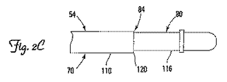
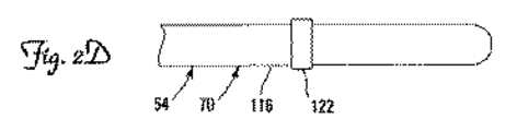
図2C〜図2Fは、本発明の種々の実施形態による、リードの偏向可能領域80を含み、かつ代表的な偏向位置84の形態を説明する遠位領域70の部分を表す。図2Cに示すように、リード本体54は、比較的硬い部分110と、硬い部分110の遠位に位置する比較的柔軟な部分116とを含む。この実施形態において、偏向位置84は、比較的硬い部分110と比較的柔軟な部分116の間の変わり目120によってリード本体54内に作られる。比較的柔軟な部分116は、曲げやすく、かつテンドン100への所与の近位の力Fで、硬い部分110に対して優先的に曲がる。一実施形態において、硬い部分110は、リード本体54内に比較的剛性の材料、例えばポリウレタンを使用することによって形成され、かつ柔軟な部分116は、より曲がりやすい材料、例えばシリコーンから形成される。もう1つの実施形態において、硬い部分110は、柔軟な部分116よりも大きな肉厚を有することができる。もう1つの実施形態において、比較的硬い部分110は、その剛性を増加させるために(例えば外面58の下に埋設された金属又は織物組紐材料によって)強化でき、他方で比較的柔軟な部分116は、強化されなくても良い。あるいは、両方の部分110、116が強化でき、比較的硬い部分110が、比較的硬い部分116よりも広範囲にわたり強化される。
2C-2F represent a portion of the
図2Dにおいて、偏向位置84は、リード本体54を局所的に硬くし、かつ電極122に遠位の、より柔軟な部分を、テンドン100へ引張荷重を加えた後に優先的に偏向させる、リード本体54上の電極122によって形成される。
In FIG. 2D, the
図2Eにおいて、偏向位置84は、偏向可能領域80が周囲で偏向できる、局所点を作る、リード本体54内のノッチ124を含む。図2Fは、リード本体54の絶縁シースの区間が、偏向位置84を作るために除去される、リード本体54内に切欠き128が作られる同様のアプローチを示す。
In FIG. 2E, the
偏向位置84を作るために図2C〜図2Fに示された実施形態は、幾つかの実施形態において、展開形態の時に偏向可能領域80の形状を更に変化させるために組み合わせることができる。例えば、リード50は、ノッチ124と同様に、硬い及び柔軟な部分110、116の間に変わり目120を含む偏向位置84を含むことができる。その上、幾つかの実施形態において、リード50の偏向可能領域80は、偏向可能領域80の偏向形状を変化させるために、1つを超える偏向位置84を含むことができる。更に、示した偏向位置の実施形態は、全く限定的でない。逆に、偏向可能領域56が周囲で偏向できる点又はゾーンを作るいかなる形態又は機構も使用できる。
The embodiments shown in FIGS. 2C-2F to create the
図3Aは、本発明のもう1つの実施形態による偏向可能領域160を示すリード150の部分断面図である。図3Aに示すように、リード150は、外面164を有し、かつ近位領域166と遠位領域167を備えた本体162を含む。近位領域166は近位端168を含み、かつ遠位領域は電極169を含み、かつ遠位先端170で終わる。内腔176は、遠位先端170へ伸長し、かつ開放遠位端180で終わる。偏向可能領域160は、第1及び第2偏向位置186、190を含む。テンドン196は、本体162内に収容され、かつ近位端168から遠位先端170に延び、かつテンドン196をリード本体162に固定して取り付けるように構成された取付構造200を含む。示した実施形態において、テンドン196は、内腔176内に配置され、かつアパーチャ204、206で本体162を通して延び、このようにしてリード本体162の外面164に沿って延びるテンドン196の一部を形成している。
FIG. 3A is a partial cross-sectional view of a lead 150 showing a
上記リード50と同様に、偏向可能領域160は、図3Aに示すような非偏向(すなわち非展開)形状と、リード150が貫通して搬送される心臓血管(例えば冠静脈洞31及び血管枝34)の1つの内面を摩擦によって係合させるように構成された組織係合面を、リード外面164が提供する、偏向(すなわち展開)形状との間で変化するように構成された固定機構を提供する。テンドン196は、遠位先端170に、テンドン196に加えられる近位に向けられた力を伝達するために働き、それにより偏向可能領域160の形状(すなわち展開)を変化させる。偏向位置186、190は、偏向可能領域160の偏向点を制御するように構成される。偏向位置186、190は、リード50に対する上記実施形態のいずれによっても構成できる。偏向可能領域が、偏向できる点を提供するための他のいかなる形態も、本発明の範囲内で使用できることが、更に認められるであろう。
Similar to the
図3Bは、偏向(すなわち展開)形態での偏向可能領域160を有するリード150を示す。図3Bに示すように、近位領域166が近位に移動することを抑制しながら引張力Fをテンドン196に加えること(すなわち、引張力を加えながら近位領域166を定位置で把握及び保持することによって)によって、テンドン196を近位領域166に対して近位に移動させる。このことは、次に偏向可能領域160を偏向位置186、190で偏向させ、このようにして図3Bに示すように偏向可能領域160の形状を変化させる。かかる偏向は、リード本体外面164を、偏向可能領域80が位置決めされる心臓血管(例えば冠静脈洞31又は血管枝34)の内面と接触させ、かつ摩擦によって係合させる。テンドン196は、次に張力を受けて、近位端(図示せず)又はその付近でリード本体162に固着できる。示した実施形態において、偏向位置190に遠位のリード150の部分は、テンドン196に対する引張力Fの作用で実質的に偏向しないままであるように、比較的硬い。あるいは、他の実施形態において、偏向位置190に遠位のリード150の部分の全部又は一部は、この引張力Fの作用で若干の偏向を受けるように比較的柔軟にすることができる。
FIG. 3B shows a lead 150 having a
示した偏向可能領域160は、2つの偏向位置186、190を含むが、他の実施形態は、追加の固定機構形状を作るために、2つを超える偏向位置を含むことができる。例えば、一実施形態において、3つ以上の偏向位置が、展開形態時にリードに正弦波偏向形状を形成するために用いられる。その上、それぞれリード50、150の偏向位置84及び186、190は、幾つかの実施形態において、それぞれの偏向可能領域の偏向方向を制御するように、リード本体上に戦略的に位置決めできる。例えば、幾つかの実施形態において、複数の偏向位置を設けることができ、各々は、リードの外周の周りを部分的にのみ延び、かつ少なくとも幾つかが、リード本体の外周の周りで互いにオフセットされる。かかる実施形態において、各々のかかる偏向位置は、リード本体を異なる方向に偏向させる傾向があり、三次元形状を有する展開形態を作る。従って、偏向位置と偏向可能領域を選択的に位置決めし構成することが、広範囲な固定形状を生成できることが認められる。
The illustrated
その上、なおも他の実施形態において、リード50及び/又は150は、各々が異なる取付位置でそれぞれのリード本体に取り付けられた1つを超えるテンドンを含むことができる。一実施形態において、リードは、遠位先端又はその付近の第1取付位置でリード本体に取り付けられた第1テンドンと、遠位先端に近位の位置でリード本体に取り付けられた第2テンドンとを含む。例えば、リード50及び/又は150は、図2B及び図3BのJ及びS字形形態の組み合わせである展開形態で複合形状を有するように構成できる。従って、一連の形状は、特に複数のテンドンが戦略的に構成された偏向位置と組合わされて使用される時に、達成できる。あるいは、リード50及び/又は150は、各々がリードの異なる偏向可能領域を偏向させるために操作可能な、複数のテンドンを含むことができる。かかる実施形態において、医師は、特定の患者の血管構造に基づき、最適な展開形態を選択できる。複数のテンドンの実施形態において、複数のテンドンの1つ以上は、図3Aに示すように主導体コイルによって形成される内腔内でなく、1つ以上の二次内腔内に配置できる。
Moreover, in still other embodiments, the
図3Cは、代表的な複数テンドンリード250を示す。図3Cに示すようにリード250は、上記リード50、150と多くの点で類似又は同一であり、かつ近位部分252、遠位先端255に終わる遠位部分254、及び全体を通した内腔256を区画する本体251を含む。遠位部分254は、第1及び第2偏向可能領域260、266を含む。第1偏向位置268は、第1偏向可能領域260に近位の本体251上に位置し、かつ第2偏向位置269は、第1及び第2偏向可能領域260、266間で本体251に位置する。更に示すように、リード250は、内腔256内の本体251内に部分的に収容され、かつ第2偏向位置269に遠位の第1取付位置273で本体251に取り付けられた第1テンドン272を含む。リード250は、内腔256内で本体251内に部分的に収容され、かつ遠位先端255に近位の第2取付位置275で本体251に取り付けられた第2テンドン272を更に含む。
FIG. 3C shows a representative
図3Cに示した実施形態において、第1テンドン272は、上記のように第1偏向可能領域260の展開を引き起こすために操作可能である。その上、第2テンドン274は、第2偏向可能領域266及び/又は第1偏向可能領域260の偏向を引き起こすために操作可能である。例えば、リード250は、第2テンドン274へ引張力を加えた後に、第2偏向可能領域266が、第2偏向位置268を優先的に偏向するように(例えば第1及び第2偏向可能領域260、266の相対剛性を差別化することによって)構成できる。リード250は、第1偏向可能領域260が、第2テンドン274に対する引張力を増加させることによってその後に偏向できるように、更に構成できる。
In the embodiment shown in FIG. 3C, the
上記のリード50、150、250の偏向可能な固定機構は、好適には所望通りにリードを再位置決め及び/又は除去するために(すなわち、それぞれのテンドンに対する引張荷重を取り除くことによって)医師がリードをその非展開形態に戻すことを可能にする。その上、所望ならば、上記の偏向可能領域は、医師が、リード電極を標的血管壁と密接に接触するように選択的に推進することを可能にする。リード50、150、250の偏向可能領域は、医師が蛇行した冠血管系を通して所望の差し込み部位へリードを操縦することを効果的に可能にすることによって、リードの搬送も容易になる。
The deflectable locking mechanism of the
幾つかの実施形態において、リード50、150、250の組織係合外面は、特にそのそれぞれの偏向可能領域において、標的冠状血管の内面との係合を強化するための機構を含む。かかる機構は、例えば粗面処理、接着又は粘着コーティング、及び線維化促進コーティングを含む。あるいは、長期間の差し込み後にリードの抜き取りを容易にするために、偏向可能領域は、組織内方成長を抑えるためにコーティング(例えばPTFEのようなポリマーコーティング)又は他の機構を含むことができる。
In some embodiments, the tissue engaging outer surface of the
図4A、図4Bは、示したものでは本発明のもう1つの実施形態による拡張可能な固定装置310である、代替的固定機構を含む、体腔(示したものでは、血管枝34である)内のリード300の遠位領域の部分を示す。図4Aに示すように、リード300は、外面320を有するリード本体316を含む。固定装置310は、リード本体316上に配置され、かつ近位アンカ326と、遠位浮動リング330とを含み、さらにアンカ326とリング330に取り付けられた径方向に拡張可能な構造336を含む。テンドン340は、本体内(例えば内腔内、図示せず)に配置され、かつリング330の1つ以上の位置に取り付けられる。本体316上のアンカ326の位置は、固定され、他方で遠位リング330は、本体316に沿って移動するように構成された浮動部材である。示した実施形態において、アンカ326は、リード本体316に固定して取り付けられたリングである。他の実施形態において、アンカ326は、リング以外の構造を有することができる。一実施形態において、径方向に拡張可能な構造336は、アンカ326を形成するためにリード本体316に直接、一端で固定して取り付けられる。
4A and 4B are within a body cavity (shown as a vascular branch 34) including an alternative fixation mechanism, which is shown,
径方向に拡張可能な構造336は、図4Aに示すような径方向に折り畳まれた(すなわち、非展開)形態から、径方向に拡張可能な構造336がリード本体316の外面320を径方向に越えて延びる図4Bに示すような径方向に拡張した(すなわち、展開)形態に拡張される。径方向に拡張した形態において、径方向に拡張可能な構造336は、血管枝34の内面344を摩擦によって係合させることによって、リード300を所望の差し込み位置に固定するように構成される。示した実施形態において、径方向に拡張可能な構造336は、血管介入手順で使用するための当該技術分野において公知のステントに似た、ステント状装置である。他の実施形態において、径方向に拡張可能な構造336は、例えばアンカ326とリング330の間に接続された、径方向に拡張可能なコイル又は複数の無作為に配向したワイヤのような他の形態を有することができる。
The radially
一実施形態において、径方向に拡張可能な構造336は、リード300を搬送するために、図4Aに示すような径方向に折り畳まれた形態に通常あり、かつ近位に向けられた引張力は、テンドン340、かつ次にリング330をリード本体316に対して近位に引っ張るために、テンドン340に加えられ、それにより径方向に拡張可能な構造336を、図4Bに示す形態に径方向に拡張させることができる。かかる1つの実施形態において、テンドン340は、径方向に拡張可能な構造336、及びそれ故に固定装置310を展開した、径方向に拡張された形態に保持するために、張力を受けて維持できる。かかる実施形態において、テンドン340は、固定装置310を展開した後に、リード本体316に固着される。固定装置310はテンドン340内の張力を解放し、従ってリード300の除去及び/又は再位置決めを可能にすることによって、図4Aの径方向に折り畳まれた形態に更に戻すことができる。
In one embodiment, the radially
あるいは、一実施形態において、リード300は、固定装置310の展開のためにリング330の近位運動を可能にするために、下方に偏向できるが、一旦係合されるとその後のリング330の遠位運動を防止する、本体316上の1つ以上の偏向可能な止め具350のような保持構造を含むことができる。しかしながら、固定装置310を図4Bの展開形態に保持する他のいかなる構造又は方法も、使用できることが強調される。
Alternatively, in one embodiment, the
もう1つの実施形態において、径方向に拡張可能な構造336は、自己拡張し、かつ例えばリング330の自発的近位運動を防止するが、テンドン340に加えられる十分な近位に向けられる力によって外す、又は打ち勝つことができる保持構造(図示せず)によって、図4Aの径方向に折り畳まれた形態に保持される。一旦保持構造が、このように外されると、径方向に拡張可能な構造336は、図4Bの形態に自己拡張できる。後出の2つの実施形態の両方とも好適には、テンドン340内の張力が、固定構造310の展開後に除去されることが可能である。その上、かかる実施形態において、テンドン340は、固定装置310から取り外し可能であっても良く、このようにして差し込み後にリード310からテンドン340を除去することを可能にする。
In another embodiment, the radially
図4Cは、テンドン340をリング330に取り付ける1つの代表的な構造を示す、リード300及び固定装置310の部分断面図である。図4Cに示すように、テンドン340は、リード本体316内でそれぞれアパーチャ356、357を通って延びる分岐セグメント352、353を含む。更に示すように、テンドンセグメント352、353は、径方向に拡張可能な構造336と外面320の間でリード本体316に沿って延び、かつリング330に取り付けられる。示した実施形態において、アパーチャ356、357は、アンカ326に近位に位置するが、他の実施形態において、アパーチャは、アンカ326とリング330の間に位置できる。幾つかの実施形態において、2つを超えるテンドンセグメントが、使用できる。図4Cから明らかなように、テンドン340が、固定装置310を展開するためにリード本体316に対して近位に引っ張られるにつれ、テンドンセグメント352、353は、アパーチャ356、357を通ってリード内腔に引っ込む。しかしながら、図4Cに示したテンドン取付実施形態は、代表的なだけであり、かつテンドン340をリング330に操作可能に結合するためのいかなる構造又は方法も、本発明の範囲内で使用できることが強調される。
FIG. 4C is a partial cross-sectional view of
もう1つの実施形態において、固定装置310は、展開されず、径方向に折り畳まれた形態にある時、リード本体316の外面320を越えて径方向に延びないように構成される。例えば、リード300は、かかる実施形態において、リード本体316の小径部分を含み、かつ固定装置310はその小径部分内に存在する。この形態は、かかる搬送中にリード本体から突き出る固定構造がないために、リード300搬送の容易さを向上させることができる。
In another embodiment, the
図5A、図5Bは、示したものでは本発明のもう1つの実施形態による自己拡張固定装置410である、代替的固定機構を含むリード400の遠位領域の部分を示す。図5A、図5Bに示すように、リード400は、固定装置410が配置される本体416を含む。更に示すように、固定装置410は、近位浮動リング426と遠位アンカ430を含み、かつ近位リング426とアンカ430に取り付けられた径方向に自己拡張する構造436とを含む。テンドン440は、リード本体416内(例えば内腔内、図示せず)に配置され、かつリング426の1つ以上の位置に取り付けられる。本体416上のアンカ430の位置は、固定され、他方でリング426は、本体416に沿って移動するように構成された浮動部材である。示した実施形態において、アンカ426は、リード本体416に固定して取り付けられたリングである。他の実施形態において、アンカ426は、リング以外の構造を有することができる。一実施形態において、径方向に拡張可能な構造は、アンカ426を形成するためにリード本体416に直接、一端で固定して取り付けられる。
5A and 5B show a portion of the distal region of the
示した実施形態において、テンドン440は、それぞれアパーチャ446、448を通してリード本体416に延び、かつリング426に取り付けられた個別のセグメント442、443を含む。他の実施形態において、テンドン440をリング426に取り付ける代替的構造が使用できる。自己拡張構造436は、上記径方向に拡張可能な構造336の自己拡張実施形態に、設計及び機能の点で実質的に類似する。
In the illustrated embodiment,
テンドン440に加えられる引張力は、リード400の搬送に対して、図5Aの径方向に折り畳まれた形態に自己拡張構造436を保持するために、近位方向にリング426を引っ張るように働く。一実施形態において、リード400は、張力を受けてリード400の近位端(図示せず)の付近に固着されたテンドン440によって、所望の差し込み位置に搬送される。一旦リード400が、所望の差し込み位置に搬送されると、テンドン440内の張力は解放され、かつ自己拡張構造は、図5Bの展開形態に拡張する。
The tensile force applied to the
図5A、図5Bの実施形態は、リードが固定装置410によって固定された後に、テンドン340を無負荷状態(すなわち張力を受けない)にすることが望ましい。その上、固定装置410は、例えばリード400を再位置決め及び/又は身体から除去するために、所望であればから図5Aの径方向に折り畳まれた状態に戻すことができる。
In the embodiment of FIGS. 5A and 5B, it is desirable that the
固定装置310、410は、差し込み型装置に適した種々の材料(例えば金属、ポリマー)から作ることができる。専ら例として、適切な材料には、ステンレス鋼及び、多種多様な合金やポリマーを含む。幾つかの実施形態において、固定装置310、410は、望ましい形状記憶及び超弾性特性を有する材料から少なくとも部分的に作られる。自己拡張固定装置に関して、適切な形状記憶及び超弾性を示す1つの代表的な材料は、ニチノールである。他の適切な材料は、前述の事項に基づき当業者によって確認されるであろう。
The
幾つかの実施形態において、固定装置410が、径方向に折り畳まれた形態にある時、リード本体416の外面420を超えて径方向に延びないように構成できることが認められるであろう。例えば、リード400は、かかる実施形態において、リード本体416の小径部分を含むことができ、かつ固定装置410は、この小径部分内に存在する。この形態は、リード400搬送の容易さを向上できる。
It will be appreciated that in some embodiments, the
図6A、図6Bは、示したものでは本発明のもう1つの実施形態による径方向に拡張可能な固定装置510である、代替的固定機構を含むリード500の遠位領域の部分を示す。図6Aに示すように、リード500は、外面520を有するリード本体516を含む。固定装置510は、リード本体516上に配置され、かつ示した実施形態において本体516に取り付けられたリングの形状にある近位アンカ526と、遠位浮動リング530を含み、かつ示した実施形態においてアンカ526とリング530に取り付けられた、ベローズ536である径方向に拡張可能な構造とを含む。テンドン540は、リード本体内(例えば内腔内、図示せず)に配置され、かつリング530の1つ以上の位置に取り付けられる。示した実施形態において、テンドン540は、上記図4Cに示したように構成され、かつリング530に取り付けられる。他の実施形態において、テンドン540をリング530に操作可能に取り付けるための代替的構造が、使用できる。本体516上のアンカ526の位置は、固定され、他方でリング530は、本体516に沿って移動するように構成された浮動部材である。
6A and 6B show a portion of the distal region of the
固定装置510は、上記の固定装置310と実質的に類似した方法で働く。従って、一実施形態において、径方向に拡張可能なベローズ536は、通常、リード500搬送のために図6Aに示したような径方向に折り畳まれた形態にある。一旦リード500が、体内に所望のように位置決めされると、近位に向けられた引張力が、テンドン540を、従ってリング530を、本体526に対して近位に引っ張るために、テンドン540に加えられ、それによりベローズ536を長手方向に圧縮し、ベローズは、図6Bに示す展開形態に径方向に拡張する。このように拡張された時、ベローズ536は、固定装置510が内部に位置決めされた心臓血管の内面を係合させることができ、それによりリード500を差し込み位置に固定する。
The
一実施形態において、一旦固定装置510が展開されると、テンドン540は、ベローズ536、及び従って固定装置510を展開形態に保持するために、張力を受けて維持でき、かつリード本体516に固着される。固定装置510は、テンドン540内の張力を解放することによって図6Aの径方向に折り畳まれた形状に更に戻すことができ、従ってリード500の除去及び/又は再位置決めを可能にする。あるいは、リード500は、他の実施形態において、一旦固定装置510が展開されると、リング530の遠位方向での動きを防止するために、上記のリード300の偏向可能な止め具350のような1つ以上の保持構造を含むことができる。他の実施形態(図示せず)において、固定装置510を図6Bの展開形態に保持するために、他の又は追加の構造が設けられる。
In one embodiment, once the anchoring
他の実施形態(図示せず)において、ベローズ536は自己拡張するように構成され、固定装置510が、上記の固定装置310、410の自己拡張実施形態とほぼ同じように、搬送のために径方向に折り畳まれた形態で抑圧される。
In other embodiments (not shown), the
ベローズ536は、所望の柔軟性及び生体適合性特性を有するいかなる材料から作られても良い。代表的な材料には、ポリウレタン及びポリエーテルエーテルケトン(PEEK(商標))のようなポリマーと、ステンレス鋼及びニチノールのような金属とを含む。
幾つかの実施形態(図示せず)において、ベローズ536は、長期固定に関して、何らかの潜在的な閉塞効果を減少させ、かつ/又は組織内方成長を促すための機構(例えば穿孔又は他の切欠き)を含むことができる。例えば、一実施形態において、ベローズ536は、リード500の外周の周りを部分的にのみ延びる。一実施形態において、ベローズ536はリード本体516の周りに径方向に配置された複数の細長いローブの形状である。
In some embodiments (not shown), the
幾つかの実施形態において、固定装置510が、径方向に折り畳まれた形態にある時、リード本体516の外面520を超えて径方向に延びないように構成できることが認められるであろう。例えば、リード500は、かかる実施形態において、リード本体516の小径部分を含むことができ、かつ固定装置510は、この小径部分内に存在できる。この形態は、リード500搬送の容易さを向上できる。
It will be appreciated that in some embodiments, the
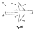
図7A、図7Bは、示したものでは本発明のもう1つの実施形態による径方向に拡張可能な固定装置610である、代替的固定機構を含むリード600の遠位領域の部分を示す。図7A、図7Bに示すように、リード600は、外面620を有するリード本体616を含む。固定装置610は、リード本体616上に配置され、かつ遠位浮動リング630を有し、そのリング630の反対側の本体に取り付けられた、複数の径方向に拡張可能なリブ636を含む。テンドン640は、本体616内(例えば内腔内、図示せず)に部分的に配置され、かつリング630の1つ以上の位置に取り付けられる。示した実施形態において、テンドン640は、上記図4Cに実質的に示したように構成され、かつリング630に取り付けられる。他の実施形態(図示せず)は、テンドン640をリング630に取り付けるための代替的構造や配置を用いることができる。リング630は、本体616に沿って移動するように構成された浮動部材である。
7A and 7B show a portion of the distal region of
一実施形態において、リブ636は、通常、リード600搬送のために図7Aに示したような径方向に折り畳まれた形態にある。一旦リード600が、体内に所望のように位置決めされると、近位に向けられた引張力が、テンドン640とリング630を、リード本体616に対して近位に引っ張るために、テンドン640に加えられ、それにより固定装置610が内部に位置決めされた心臓血管の内面を係合させ、従ってリード600を差し込み位置に固定するために、リブ636の中央部分を、図7Bに示す形態に、径方向に拡張させる。
In one embodiment, the
一実施形態において、一旦固定装置610が展開されると、テンドン640は、径方向に拡張可能な構造636、及び従って固定装置610を展開され、径方向に拡張された形態に保持するために、張力を受けて維持でき、かつリード本体616に固着される。固定装置610は、テンドン640内の張力を解放することによって図7Aの径方向に折り畳まれた形状に更に戻すことができ、従ってリード600の除去及び/又は再位置決めを可能にする。あるいは、他の実施形態において、リード600は、一旦固定装置610が展開されると、リング630の遠位方向での動きを防止するために、上記のリード300の1つ以上の偏向可能な止め具350のような1つ以上の保持構造を含むことができる。他の実施形態(図示せず)において、固定装置610を図7Bの展開形態に保持するために、他の又は追加の構造が設けられる。固定装置をその展開形態に保持するための示した構造及び方法は、専ら代表的であることが、再度強調される。
In one embodiment, once the anchoring
もう1つの実施形態において、リブ636は、自己拡張し、かつ例えばリング630の自発的近位動きを防止するが、テンドン640に加えられる十分な近位に向けられた力によって外すことができる保持構造(図示せず)によって、図7Aの径方向に折り畳まれた形態で保持される。一旦保持構造が、外されると、リブ636は、図7Bの形態に自己拡張できる。後出の2つの実施形態の両方とも好適には、テンドン640内の張力が、固定構造610の展開後に除去されることを可能にする。
In another embodiment, the
図7Cは、血管(例えば血管枝34)の内面に係合させるために、径方向に拡張された形態のリブ636を示す、リード600の端面図である。図7A〜図7Cのリード600がほぼ180度離して配向された2つの径方向に拡張可能なリブ636を含むが、他の実施形態において、1つ又は2つを超えるリブが使用できることが認められるであろう。一実施形態において、リード600は、単一の径方向に拡張可能なリブ636を含む。もう1つの実施形態において、リード600は、ほぼ90度離して配向された2つのリブ636を含む。かかる実施形態において、リブ636は、リード電極を標的組織(例えば心筋)に偏らせるように大きさを決めることができ、かつ配向される。リブ636の数と配向の他の変形例は、前述の事項に基づき、当業者にとって明瞭であろう。
FIG. 7C is an end view of
図8A、図8Bは、示したものでは本発明のもう1つの実施形態による自己拡張固定装置710である、代替的固定機構を含むリード700の遠位領域の部分を示す。図8A、図8Bに示すように、リード700は、固定装置710が配置される本体716を含む。更に示すように、固定装置710は、近位浮動リング726と、リング726の反対端の本体716に取り付けられた、複数の径方向に自己拡張するリブ736とを含む。テンドン740は、本体716内(例えば内腔内、図示せず)に配置され、かつリング726上の1つ以上の位置に取り付けられる。示した実施形態において、テンドン740の部分は、アパーチャ746を通って本体716内に、かつ外面720に沿って、それが取り付けられるリング726に延びる。他の実施形態(図示せず)は、テンドン740をリング726に取り付けるための代替的配置を用いることができる。
8A and 8B show a portion of the distal region of
テンドン740に加えられる引張力は、リード700の搬送のために、図7Aの径方向に折り畳まれた形態に自己拡張リブ736を保持するために近位方向に近位リング726を引っ張るように働く。一実施形態において、テンドン740は、張力を受けてリード700の近位端(図示せず)の付近に固着される。一旦リード700が、所望の差し込み位置に搬送されると、テンドン740内の張力は、解放され、かつ自己拡張リブ736は、図8Bに示すような展開形態に拡張する。
The tensile force applied to the
示した実施形態において、リブ636、736は、径方向に折り畳まれた、展開されない形態にある時、それぞれのリード本体の外面620、720の外側に配置されて示される。もう1つの実施形態(図示せず)において、リブは、例えばリード本体内に形成されたスロット内に存在することによって、径方向に折り畳まれた形態にある時、それぞれの外面と実質的に一体に重なることができる。その上、幾つかの実施形態において、リブは、リード本体と一体的に形成できる。他の実施形態において、固定装置610、710は、別個の要素であっても良く、リブは、アンカ(図示せず)に取り付けられ、アンカは、次にリード本体に取り付けられる。
In the illustrated embodiment, the
リブ636、736は、幾つかの実施形態において、固定装置300、400に関連して以上に記載された材料のいずれから形成されても良い。特に自己拡張リブ実施形態において、リブは、例えばニチノールのような、望ましい形状記憶及び超弾性特性を有する材料から少なくとも部分的に作られる。他の実施形態において、リブは、リード本体を形成するために使用される同じ材料(例えば、ポリウレタン及び/又はシリコーン)から形成できる。
The
幾つかの実施形態において、リブ636、736は、所望であれば、リードの抜き取りを容易にするように構成される。例えば、一実施形態において、リブ636及び/又は736は、リブ及びそれぞれのリードの間の空間内での組織内方成長を防止又は実質的に妨げるために内方成長耐性材料(例えばPTFE)でできたポリマー膜(図示せず)を含むことができる。他の実施形態において、リブ636、736自体は、組織内方成長に耐性を有するPTFEのような材料から作ることができる。幾つかの実施形態において、リブ636、736は、長期にわたる差し込み期間後にでも抜き取りを容易にするために、当該技術分野において公知であるような、再吸収可能な材料で作られていても良い。
In some embodiments, the
図9A、図9Bは、示したものでは本発明のもう1つの実施形態による径方向に拡張可能な固定装置810である、代替的固定機構を含むリード800の遠位領域の部分を示す。図9A、図9Bに示すように、リード800は、外面820を有するリード本体816を含む。固定装置810は、リード本体616上に配置され、かつ近位部分827と、遠位部分828と、遠位端832に浮動強化リング830とを有するシース826を含む。テンドン840は、本体816内(例えば内腔内、図示せず)に部分的に配置され、かつ例えばリード300、500、600と関連して以上に記載したものと実質的に同じ方法で遠位リング830上の1つ以上の位置に取り付けられる。シース826の近位部分827は、リード本体816の外面820に摩擦によって結合される。強化リング830は、リード本体816に沿って移動するように構成される。
9A and 9B show a portion of the distal region of the
示した実施形態において、シース826は、通常、リード800搬送のために図9Aに示したような径方向に折り畳まれた形態にあり、かつ引張力は、固定装置810を展開するために、テンドン840及び強化リング830を、リード本体816に対して近位に引っ張るために、テンドン840に加えられる。近位部分827と外面820を結合する摩擦力は、近位部分827が、テンドン840に対する引張力の作用によって、リード本体816に沿って近位に滑動することを防止する。しかしながらシース826の遠位部分828は、強化リング830が、テンドン840に対する引張力の作用によって、近位に引っ張られるように十分に柔軟であり、遠位部分828は、リード固定のための組織係合面を形成するために、図9Bに示すように一団となり、かつ径方向外側に拡張する傾向がある。
In the illustrated embodiment, the
上記の種々の実施形態と同様に、テンドン840は、一実施形態において、シース遠位部分828を図9Bに示すその展開形態に維持するために、張力を受けてリード本体816に固着される。他の実施形態において、リード800は、一旦固定装置810が展開されると、強化リング830の遠位方向での動きを防止するために、上記の保持構造のような構造を含むことができる。上記の実施形態と同様に、固定装置810を図9Bの展開形態に保持するための他のいかなる構造又は方法も使用できる。
Similar to the various embodiments described above, the
シース826は、所望の柔軟性を提供するいかなる構造も有することができる。一実施形態において、シース826は、ポリマーコーティングを含んでも、含まなくても良い編組管であっても良い。一実施形態において、シース826は、強化、又は非強化ポリマー管であっても良い。幾つかの実施形態において、シース826は、組織内方成長を抑える又は実質的に防止する材料(例えばPTFE)のコーティング又は層を含む。
The
種々の実施形態のテンドンは、所望の柔軟性を有し、かつテンドンが張力を受けて維持される実施形態において、所望の疲労応答特性を有しながら、静的引張荷重を受け、かつ伝達することが可能な、いかなる構造も有することができる。例えば、テンドンは、ワイヤ、ケーブル又は糸の形状であっても良い。適切なテンドン材料には、当該技術分野において公知の縫合材料や、ステンレス鋼のような他のポリマー及び金属又はニチノールのような超弾性合金を含むが、限定されない。テンドンは、テンドン及びテンドンを担持するそれぞれの内腔の内壁の間の摩擦力を減少させるために任意に潤滑性材料で被覆できる。 The tendons of the various embodiments have the desired flexibility and, in embodiments where the tendons are maintained under tension, receive and transmit static tensile loads while having the desired fatigue response characteristics. It can have any structure possible. For example, the tendon may be in the form of a wire, cable or thread. Suitable tendon materials include, but are not limited to, suture materials known in the art, other polymers such as stainless steel, and metals or superelastic alloys such as nitinol. The tendon can optionally be coated with a lubricious material to reduce the frictional force between the tendon and the inner wall of the respective lumen carrying the tendon.
以上に記載された固定機構のいずれか又は全ては、急性及び/又は長期固定の摩擦係合を所望のように強化するために、追加の機構を含むことができる。専ら例として、かかる機構は、心臓血管組織との摩擦係合を増加させるために、粗面処理又は他の表面処理を含む。その上、除去できることが望まれる幾つかの実施形態において、固定機構は、組織内方成長を抑え、かつ所望であればリードの除去及び/又は再位置決めを容易にするために、ポリマーコーティング又は他の機構を含むことができる。 Any or all of the locking mechanisms described above can include additional mechanisms to enhance acute and / or long-term fixed frictional engagement as desired. By way of example only, such mechanisms include roughening or other surface treatments to increase frictional engagement with cardiovascular tissue. Moreover, in some embodiments where it is desired to be removable, the fixation mechanism can be polymer coating or other to reduce tissue ingrowth and facilitate lead removal and / or repositioning if desired. Can be included.
幾つかの実施形態において、径方向に拡張可能な固定装置が、それぞれのリード本体の周りを完全に円周方向に延びないことが強調される。その上、浮動部材(例えば固定装置310のリング330)は、リード本体に沿った移動を可能にするように構成されたいかなる構造も有することができる。例えば、浮動部材は、リード本体内のスロットに乗るように構成でき、かつ示された実施形態に示すようなリングとして構成される必要はない。
It is emphasized that in some embodiments, the radially expandable fixation device does not extend completely circumferentially around each lead body. In addition, the floating member (eg,
従って、上記の展開可能な固定機構のいずれかを使用して、標的心臓血管内に心臓リードの部分を固定するために、リードは、非展開状態での固定機構によって、その差し込み位置に最初に経静脈的に搬送される。かかるリード搬送は、いかなる方法によっても、かつ現在知られている(例えば、ガイドカテーテル、ガイドワイヤ)、又は後で開発されるいかなる搬送装置を使用しても達成できる。一旦リードが、搬送されると、テンドン(又は幾つかの実施形態において、複数のテンドン)は、固定機構を展開し、かつリードをその差し込み位置に固着するために作動できる。 Thus, in order to secure a portion of a cardiac lead within a target cardiovascular vessel using any of the deployable fixation mechanisms described above, the lead is first brought into its insertion position by the fixation mechanism in an undeployed state. Transported intravenously. Such lead delivery can be accomplished by any method and using any currently known delivery device (eg, guide catheter, guidewire) or any later developed delivery device. Once the lead is transported, the tendon (or in some embodiments, multiple tendons) can be activated to deploy the securing mechanism and secure the lead in its insertion position.
テンドンに加えられた引張力により、固定機構が展開するようになる(例えば上記のリード50、150、250、300、500、600、800)実施形態において、引張力が、テンドンに加えられる時、リードは、リード自体が引張力の作用によって移動することを防止するように、定位置に保持される。専ら例として、上記のリード300に関して、引張力が、径方向に拡張可能な構造336を拡張するために、テンドン340に加えられる間、リードの近位端は、定位置に保持される。一旦固定機構が、それぞれの心臓血管壁と摩擦係合して展開されると、テンドンは、固定機構をその展開形態に保持するために、必要ならばリードに固着される。あるいは、固定機構をその展開形態に保持するために、他の構造(例えばリード300の保持構造350)を含む実施形態において、テンドン内の張力は、展開後に取り除くことができるか、又はテンドンは、所望であればリードから完全に除去できる。
In embodiments where the tensile force applied to the tendon causes the anchoring mechanism to unfold (eg, the
テンドン内の張力によってその非展開形態に保持される自己拡張固定機構を利用する他の実施形態において(例えば上記リード400、700)、張力は、リードが、上記のようなその差し込み位置に搬送された後に除去される。この張力の除去は、このようにして固定機構を作動させ、かつ固定機構が、それぞれの血管壁を摩擦によって係合させるようにする。テンドンは、リード内の定位置に残ることができるか、又は所望であれば(例えばテンドンの切断によって)除去される。
In other embodiments that utilize a self-expanding locking mechanism that is held in its undeployed configuration by tension within the tendon (eg, the
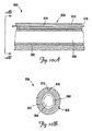
図10A、図10Bは、以上に示し、かつ記載された種々の固定機構を含むように構成された複数内腔リード850の部分の部分断面図である。図10A、図10Bに示すように、リード850は、外側絶縁シース858と、絶縁シース858によって被覆され、かつ一次内腔866を形成している導体コイル860とを含む本体856を含む。更に示すように、二次内腔870が、前述の固定機構のいずれとの使用にも適応した、テンドン876を担持する絶縁シース858内に配置される。従って、示した実施形態において、固定機構(図示せず)を展開するテンドン876は、一次内腔866によって担持されない。複数内腔リード850は、本明細書に示され、かつ以上に記載された展開可能な固定機構のいずれとも使用できることが強調される。その上、幾つかの実施形態において、追加のテンドンを収容するため、又は他の目的で(例えば薬剤搬送)、1つを超える二次内腔が、提供できる。
10A and 10B are partial cross-sectional views of portions of a
種々の修正及び追加が、本発明の範囲から逸脱することなく、論じられた代表的な実施形態に加えることができる。例えば、以上に記載した実施形態は、特定の特徴を参照するが、本発明の範囲は、特徴の異なる組み合わせを有する実施形態、及び記載された特徴の全てを含まない実施形態も含む。従って、本発明の範囲は、請求項の範囲に入るような全てのかかる代替案、修正、及び変形例を、その全ての同等物と共に包含することが意図される。 Various modifications and additions can be made to the exemplary embodiments discussed without departing from the scope of the present invention. For example, although the embodiments described above refer to particular features, the scope of the invention includes embodiments having different combinations of features and embodiments that do not include all of the described features. Accordingly, the scope of the invention is intended to embrace all such alternatives, modifications and variations as fall within the scope of the claims, along with all equivalents thereof.
Claims (16)
前記パルス発生器に結合された近位端を有するリードとを含み、
前記リードは、心臓血管内に部分的に差し込まれるように構成され、かつ
近位領域と遠位領域を備えた細長いリード本体であって、前記遠位領域が前記本体上に電極と、前記本体上に偏向位置と、組織係合外面を有する偏向可能領域とを含むリード本体と、
前記本体内に少なくとも部分的に配置され、かつ前記偏向可能領域に遠位の第1取付位置で張力を受けて前記本体に取り付けられたテンドンと
を含む差し込み型システムであって
前記テンドン内の張力は、前記組織係合外面が、前記心臓血管の内面を摩擦によって係合させることができる、前記偏向可能領域を偏向形状に維持するシステム。 A pulse generator;
A lead having a proximal end coupled to the pulse generator;
The lead is an elongated lead body configured to be partially inserted into a cardiovascular and having a proximal region and a distal region, the distal region being an electrode on the body, the body A lead body including a deflection position thereon and a deflectable region having a tissue engaging outer surface;
A plug-in system comprising a tendon that is at least partially disposed within the body and is tensioned and attached to the body at a first attachment position distal to the deflectable region, the tension in the tendon A system for maintaining the deflectable region in a deflected shape, wherein the tissue engaging outer surface can frictionally engage the inner surface of the cardiovascular vessel.
前記第1偏向可能領域に遠位の第1取付位置で張力を受けて前記リード本体内に少なくとも部分的に収容され、かつ前記リード本体に取り付けられた第1テンドンと、
前記第2偏向可能領域に遠位の第2取付位置で張力を受けて前記リード本体内に少なくとも部分的に収容され、かつ前記リード本体に取り付けられた第2テンドンと
を含む医療用電気リードであって、
前記第1及び第2テンドン内の張力が、前記第1及び第2偏向可能領域を偏向状態に維持するリード。 An elongate body comprising a proximal region and a distal region, wherein the distal region is configured to be partially inserted into a cardiovascular vessel, and at least one electrode on the body; A body including two deflectable regions;
A first tendon that is tensioned at a first attachment location distal to the first deflectable region and is at least partially received within the lead body and attached to the lead body;
A medical electrical lead including: a second tendon that is tensioned at a second attachment location distal to the second deflectable region and is at least partially received within the lead body and attached to the lead body. There,
A lead in which tension in the first and second tendons maintains the first and second deflectable regions in a deflected state.
Applications Claiming Priority (2)
| Application Number | Priority Date | Filing Date | Title |
|---|---|---|---|
| US11/421,990 US7890174B2 (en) | 2006-06-02 | 2006-06-02 | Medical electrical lead with deployable fixation features |
| PCT/US2007/067885 WO2007143304A2 (en) | 2006-06-02 | 2007-05-01 | Medical electrical lead with deployable fixation features |
Publications (2)
| Publication Number | Publication Date |
|---|---|
| JP2009539425A true JP2009539425A (en) | 2009-11-19 |
| JP2009539425A5 JP2009539425A5 (en) | 2010-06-17 |
Family
ID=38543930
Family Applications (1)
| Application Number | Title | Priority Date | Filing Date |
|---|---|---|---|
| JP2009513360A Pending JP2009539425A (en) | 2006-06-02 | 2007-05-01 | Medical electrical lead with deployable securing mechanism |
Country Status (5)
| Country | Link |
|---|---|
| US (1) | US7890174B2 (en) |
| EP (1) | EP2051771B1 (en) |
| JP (1) | JP2009539425A (en) |
| AT (1) | ATE549059T1 (en) |
| WO (1) | WO2007143304A2 (en) |
Cited By (11)
| Publication number | Priority date | Publication date | Assignee | Title |
|---|---|---|---|---|
| JP2013526346A (en) * | 2010-05-10 | 2013-06-24 | スパイナル・モデュレーション・インコーポレイテッド | Method, system and device for suppressing misalignment |
| US8983624B2 (en) | 2006-12-06 | 2015-03-17 | Spinal Modulation, Inc. | Delivery devices, systems and methods for stimulating nerve tissue on multiple spinal levels |
| US9044592B2 (en) | 2007-01-29 | 2015-06-02 | Spinal Modulation, Inc. | Sutureless lead retention features |
| US9056197B2 (en) | 2008-10-27 | 2015-06-16 | Spinal Modulation, Inc. | Selective stimulation systems and signal parameters for medical conditions |
| US9205261B2 (en) | 2004-09-08 | 2015-12-08 | The Board Of Trustees Of The Leland Stanford Junior University | Neurostimulation methods and systems |
| US9259569B2 (en) | 2009-05-15 | 2016-02-16 | Daniel M. Brounstein | Methods, systems and devices for neuromodulating spinal anatomy |
| US9314618B2 (en) | 2006-12-06 | 2016-04-19 | Spinal Modulation, Inc. | Implantable flexible circuit leads and methods of use |
| US9327110B2 (en) | 2009-10-27 | 2016-05-03 | St. Jude Medical Luxembourg Holdings SMI S.A.R.L. (“SJM LUX SMI”) | Devices, systems and methods for the targeted treatment of movement disorders |
| US9427570B2 (en) | 2006-12-06 | 2016-08-30 | St. Jude Medical Luxembourg Holdings SMI S.A.R.L. (“SJM LUX SMI”) | Expandable stimulation leads and methods of use |
| US9468762B2 (en) | 2009-03-24 | 2016-10-18 | St. Jude Medical Luxembourg Holdings SMI S.A.R.L. (“SJM LUX SMI”) | Pain management with stimulation subthreshold to paresthesia |
| US10232180B2 (en) | 2004-09-08 | 2019-03-19 | The Board Of Trustees Of The Leland Stanford Junior University | Selective stimulation to modulate the sympathetic nervous system |
Families Citing this family (28)
| Publication number | Priority date | Publication date | Assignee | Title |
|---|---|---|---|---|
| US20030199961A1 (en) * | 2002-04-03 | 2003-10-23 | Bjorklund Vicki L. | Method and apparatus for fixating a pacing lead of an implantable medical device |
| US7657482B1 (en) * | 2002-07-15 | 2010-02-02 | Paymentech, L.P. | System and apparatus for transaction fraud processing |
| US8532793B2 (en) | 2008-04-30 | 2013-09-10 | Medtronic, Inc. | Techniques for placing medical leads for electrical stimulation of nerve tissue |
| US8611996B2 (en) | 2008-10-31 | 2013-12-17 | Medtronic, Inc. | Implantable medical device crosstalk evaluation and mitigation |
| US8249708B2 (en) | 2008-10-31 | 2012-08-21 | Medtronic, Inc. | Implantable medical device crosstalk evaluation and mitigation |
| US8532779B2 (en) | 2008-10-31 | 2013-09-10 | Medtronic, Inc. | Implantable medical device crosstalk evaluation and mitigation |
| US9597505B2 (en) | 2008-10-31 | 2017-03-21 | Medtronic, Inc. | Implantable medical device crosstalk evaluation and mitigation |
| US8774918B2 (en) | 2008-10-31 | 2014-07-08 | Medtronic, Inc. | Implantable medical device crosstalk evaluation and mitigation |
| US8688210B2 (en) | 2008-10-31 | 2014-04-01 | Medtronic, Inc. | Implantable medical device crosstalk evaluation and mitigation |
| US9775987B2 (en) | 2008-10-31 | 2017-10-03 | Medtronic, Inc. | Implantable medical device crosstalk evaluation and mitigation |
| US8005539B2 (en) | 2008-10-31 | 2011-08-23 | Medtronic, Inc. | Implantable medical device crosstalk evaluation and mitigation |
| US8260412B2 (en) | 2008-10-31 | 2012-09-04 | Medtronic, Inc. | Implantable medical device crosstalk evaluation and mitigation |
| US8452394B2 (en) | 2008-10-31 | 2013-05-28 | Medtronic, Inc. | Implantable medical device crosstalk evaluation and mitigation |
| US20110004288A1 (en) * | 2009-06-12 | 2011-01-06 | Terrance Ransbury | Intravascular implantable device having integrated anchor mechanism |
| US8521305B2 (en) | 2010-05-11 | 2013-08-27 | St. Jude Medical, Inc. | Percutaneous lead with distal fixation |
| US9744349B2 (en) * | 2011-02-10 | 2017-08-29 | Respicardia, Inc. | Medical lead and implantation |
| EP2701795B1 (en) | 2011-04-28 | 2020-12-09 | Interventional Autonomics Corporation | Neuromodulation systems for treating acute heart failure syndromes |
| US20130072995A1 (en) | 2011-07-11 | 2013-03-21 | Terrance Ransbury | Catheter system for acute neuromodulation |
| JP6095658B2 (en) | 2011-07-11 | 2017-03-15 | インターベンショナル オートノミックス コーポレーション | System and method for neuromodulation therapy |
| US9446240B2 (en) | 2011-07-11 | 2016-09-20 | Interventional Autonomics Corporation | System and method for neuromodulation |
| US20130158640A1 (en) * | 2011-12-19 | 2013-06-20 | Brian D. Soltis | Lead anchoring system with limited movement of anchoring device along lead |
| WO2013096627A1 (en) * | 2011-12-21 | 2013-06-27 | Cardiac Pacemakers, Inc. | Directional features for implantable medical leads |
| US20130245739A1 (en) * | 2012-03-14 | 2013-09-19 | Anatoly Arber | Self-anchored stimulator lead and method of insertion |
| EP2911737A1 (en) | 2012-10-29 | 2015-09-02 | Cardiac Pacemakers, Inc. | Suture sleeves having exterior surface tear resistance |
| US9486622B2 (en) | 2012-11-08 | 2016-11-08 | Cardiac Pacemakers, Inc. | Fixation and strain relief element for temporary therapy delivery device |
| US10315028B2 (en) | 2014-04-23 | 2019-06-11 | Medtronic, Inc. | Active fixation medical electrical lead |
| CN107592821B (en) * | 2015-05-13 | 2021-11-23 | 美敦力公司 | Securing an implantable medical device in place while reducing perforation |
| JP6543721B2 (en) | 2015-05-20 | 2019-07-10 | カーディアック ペースメイカーズ, インコーポレイテッド | Fully integrated lead stabilizer for medical electrical leads and mounting method |
Citations (6)
| Publication number | Priority date | Publication date | Assignee | Title |
|---|---|---|---|---|
| JPH09506541A (en) * | 1995-04-28 | 1997-06-30 | ターゲット セラピューティクス, インコーポレイテッド | High performance braided catheter |
| JPH11239617A (en) * | 1997-11-13 | 1999-09-07 | Impella Cardiotechnik Gmbh | Improved cannula device |
| JP2001029480A (en) * | 1999-07-23 | 2001-02-06 | Terumo Corp | Electrode lead implanted in organism |
| JP2002501769A (en) * | 1997-10-30 | 2002-01-22 | イー.ピー. テクノロジーズ, インコーポレイテッド | Catheter distal assembly with pull wire |
| WO2005076820A2 (en) * | 2004-02-09 | 2005-08-25 | Cryocor, Inc. | Catheter articulation segment with alternating cuts |
| JP2006507104A (en) * | 2002-11-25 | 2006-03-02 | エドワーズ ライフサイエンシーズ アクチェンゲゼルシャフト | Method and apparatus for remodeling extravascular tissue structure |
Family Cites Families (11)
| Publication number | Priority date | Publication date | Assignee | Title |
|---|---|---|---|---|
| US4072154A (en) * | 1976-05-28 | 1978-02-07 | Cardiac Pacemakers, Inc. | Sealing arrangement for heart pacer electrode leads |
| US4401120A (en) * | 1978-11-06 | 1983-08-30 | Medtronic, Inc. | Digital cardiac pacemaker with program acceptance indicator |
| US5545206A (en) * | 1994-12-22 | 1996-08-13 | Ventritex, Inc. | Low profile lead with automatic tine activation |
| US6445958B1 (en) * | 1999-04-15 | 2002-09-03 | Intermedics, Inc. | Steerable coronary sinus defibrillation lead |
| US6697676B2 (en) * | 2000-12-21 | 2004-02-24 | Medtronic, Inc. | Medical electrical lead having an expandable electrode assembly |
| US6610058B2 (en) * | 2001-05-02 | 2003-08-26 | Cardiac Pacemakers, Inc. | Dual-profile steerable catheter |
| US6616628B2 (en) * | 2001-11-16 | 2003-09-09 | Cardiac Pacemakers, Inc. | Steerable catheter with a longitudinally adjustable curved core |
| WO2003047448A1 (en) * | 2001-11-29 | 2003-06-12 | Medwaves, Inc. | Radio-frequency-based catheter system with improved deflection and steering mechanisms |
| US6755812B2 (en) * | 2001-12-11 | 2004-06-29 | Cardiac Pacemakers, Inc. | Deflectable telescoping guide catheter |
| US6869414B2 (en) * | 2002-03-22 | 2005-03-22 | Cardiac Pacemakers, Inc. | Pre-shaped catheter with proximal articulation and pre-formed distal end |
| US20030199961A1 (en) | 2002-04-03 | 2003-10-23 | Bjorklund Vicki L. | Method and apparatus for fixating a pacing lead of an implantable medical device |
-
2006
- 2006-06-02 US US11/421,990 patent/US7890174B2/en not_active Expired - Fee Related
-
2007
- 2007-05-01 JP JP2009513360A patent/JP2009539425A/en active Pending
- 2007-05-01 AT AT07761645T patent/ATE549059T1/en active
- 2007-05-01 EP EP07761645A patent/EP2051771B1/en not_active Not-in-force
- 2007-05-01 WO PCT/US2007/067885 patent/WO2007143304A2/en active Application Filing
Patent Citations (6)
| Publication number | Priority date | Publication date | Assignee | Title |
|---|---|---|---|---|
| JPH09506541A (en) * | 1995-04-28 | 1997-06-30 | ターゲット セラピューティクス, インコーポレイテッド | High performance braided catheter |
| JP2002501769A (en) * | 1997-10-30 | 2002-01-22 | イー.ピー. テクノロジーズ, インコーポレイテッド | Catheter distal assembly with pull wire |
| JPH11239617A (en) * | 1997-11-13 | 1999-09-07 | Impella Cardiotechnik Gmbh | Improved cannula device |
| JP2001029480A (en) * | 1999-07-23 | 2001-02-06 | Terumo Corp | Electrode lead implanted in organism |
| JP2006507104A (en) * | 2002-11-25 | 2006-03-02 | エドワーズ ライフサイエンシーズ アクチェンゲゼルシャフト | Method and apparatus for remodeling extravascular tissue structure |
| WO2005076820A2 (en) * | 2004-02-09 | 2005-08-25 | Cryocor, Inc. | Catheter articulation segment with alternating cuts |
Cited By (15)
| Publication number | Priority date | Publication date | Assignee | Title |
|---|---|---|---|---|
| US9205261B2 (en) | 2004-09-08 | 2015-12-08 | The Board Of Trustees Of The Leland Stanford Junior University | Neurostimulation methods and systems |
| US10232180B2 (en) | 2004-09-08 | 2019-03-19 | The Board Of Trustees Of The Leland Stanford Junior University | Selective stimulation to modulate the sympathetic nervous system |
| US9427570B2 (en) | 2006-12-06 | 2016-08-30 | St. Jude Medical Luxembourg Holdings SMI S.A.R.L. (“SJM LUX SMI”) | Expandable stimulation leads and methods of use |
| US9314618B2 (en) | 2006-12-06 | 2016-04-19 | Spinal Modulation, Inc. | Implantable flexible circuit leads and methods of use |
| US9623233B2 (en) | 2006-12-06 | 2017-04-18 | St. Jude Medical Luxembourg Holdings SMI S.A.R.L. (“SJM LUX SMI”) | Delivery devices, systems and methods for stimulating nerve tissue on multiple spinal levels |
| US8983624B2 (en) | 2006-12-06 | 2015-03-17 | Spinal Modulation, Inc. | Delivery devices, systems and methods for stimulating nerve tissue on multiple spinal levels |
| US9044592B2 (en) | 2007-01-29 | 2015-06-02 | Spinal Modulation, Inc. | Sutureless lead retention features |
| US9056197B2 (en) | 2008-10-27 | 2015-06-16 | Spinal Modulation, Inc. | Selective stimulation systems and signal parameters for medical conditions |
| US9409021B2 (en) | 2008-10-27 | 2016-08-09 | St. Jude Medical Luxembourg Holdings SMI S.A.R.L. | Selective stimulation systems and signal parameters for medical conditions |
| US11890472B2 (en) | 2008-10-27 | 2024-02-06 | Tc1 Llc | Selective stimulation systems and signal parameters for medical conditions |
| US9468762B2 (en) | 2009-03-24 | 2016-10-18 | St. Jude Medical Luxembourg Holdings SMI S.A.R.L. (“SJM LUX SMI”) | Pain management with stimulation subthreshold to paresthesia |
| US9259569B2 (en) | 2009-05-15 | 2016-02-16 | Daniel M. Brounstein | Methods, systems and devices for neuromodulating spinal anatomy |
| US9327110B2 (en) | 2009-10-27 | 2016-05-03 | St. Jude Medical Luxembourg Holdings SMI S.A.R.L. (“SJM LUX SMI”) | Devices, systems and methods for the targeted treatment of movement disorders |
| JP2013526346A (en) * | 2010-05-10 | 2013-06-24 | スパイナル・モデュレーション・インコーポレイテッド | Method, system and device for suppressing misalignment |
| US11413451B2 (en) | 2010-05-10 | 2022-08-16 | St. Jude Medical Luxembourg Holdings SMI S.A.R.L. (“SJM LUX SMI”) | Methods, systems and devices for reducing migration |
Also Published As
| Publication number | Publication date |
|---|---|
| WO2007143304A3 (en) | 2008-03-27 |
| WO2007143304A2 (en) | 2007-12-13 |
| EP2051771A2 (en) | 2009-04-29 |
| ATE549059T1 (en) | 2012-03-15 |
| US7890174B2 (en) | 2011-02-15 |
| EP2051771B1 (en) | 2012-03-14 |
| US20070282412A1 (en) | 2007-12-06 |
Similar Documents
| Publication | Publication Date | Title |
|---|---|---|
| JP5214595B2 (en) | Medical electrical lead with deployable securing mechanism | |
| JP2009539425A (en) | Medical electrical lead with deployable securing mechanism | |
| JP5108876B2 (en) | Cardiac lead assembly having a pluggable stiffening structure for fixation | |
| US7477946B2 (en) | Fixation device for coronary venous lead | |
| US7801627B2 (en) | Cardiac lead having self-expanding fixation features | |
| US8712553B2 (en) | Means to securely fixate pacing leads and/or sensors in vessels | |
| EP2827944B1 (en) | Systems and methods for stimulation of vagus nerve | |
| EP3420921B1 (en) | Devices for catheter advancement and delivery of anchors | |
| JP5048764B2 (en) | Cardiac lead with stiffening structure for fixation | |
| JP5327875B2 (en) | Expandable member for intravenous lead fixation | |
| US20180154123A1 (en) | Implants and systems for electrically isolating one or more pulminary veins | |
| US8086324B1 (en) | Intrapericardial lead with distal region configured to optimize lead extraction |
Legal Events
| Date | Code | Title | Description |
|---|---|---|---|
| A521 | Request for written amendment filed |
Free format text: JAPANESE INTERMEDIATE CODE: A523 Effective date: 20100422 |
|
| A621 | Written request for application examination |
Free format text: JAPANESE INTERMEDIATE CODE: A621 Effective date: 20100422 |
|
| RD04 | Notification of resignation of power of attorney |
Free format text: JAPANESE INTERMEDIATE CODE: A7424 Effective date: 20120301 |
|
| A131 | Notification of reasons for refusal |
Free format text: JAPANESE INTERMEDIATE CODE: A131 Effective date: 20120306 |
|
| A601 | Written request for extension of time |
Free format text: JAPANESE INTERMEDIATE CODE: A601 Effective date: 20120601 |
|
| A602 | Written permission of extension of time |
Free format text: JAPANESE INTERMEDIATE CODE: A602 Effective date: 20120608 |
|
| A521 | Request for written amendment filed |
Free format text: JAPANESE INTERMEDIATE CODE: A523 Effective date: 20120905 |
|
| A02 | Decision of refusal |
Free format text: JAPANESE INTERMEDIATE CODE: A02 Effective date: 20121010 |