JP2006507104A - Method and apparatus for remodeling extravascular tissue structure - Google Patents
Method and apparatus for remodeling extravascular tissue structure Download PDFInfo
- Publication number
- JP2006507104A JP2006507104A JP2005510332A JP2005510332A JP2006507104A JP 2006507104 A JP2006507104 A JP 2006507104A JP 2005510332 A JP2005510332 A JP 2005510332A JP 2005510332 A JP2005510332 A JP 2005510332A JP 2006507104 A JP2006507104 A JP 2006507104A
- Authority
- JP
- Japan
- Prior art keywords
- implant
- proximal
- distal
- configuration
- forming element
- Prior art date
- Legal status (The legal status is an assumption and is not a legal conclusion. Google has not performed a legal analysis and makes no representation as to the accuracy of the status listed.)
- Granted
Links
- 238000000034 method Methods 0.000 title claims abstract description 90
- 238000007634 remodeling Methods 0.000 title claims abstract description 52
- 210000004115 mitral valve Anatomy 0.000 claims abstract description 45
- 239000007943 implant Substances 0.000 claims description 267
- 210000003748 coronary sinus Anatomy 0.000 claims description 85
- 230000008878 coupling Effects 0.000 claims description 36
- 238000010168 coupling process Methods 0.000 claims description 36
- 238000005859 coupling reaction Methods 0.000 claims description 36
- 230000004323 axial length Effects 0.000 claims description 16
- 230000004044 response Effects 0.000 claims description 16
- 210000004204 blood vessel Anatomy 0.000 claims description 12
- 238000000576 coating method Methods 0.000 claims description 4
- 239000011248 coating agent Substances 0.000 claims description 3
- 210000003462 vein Anatomy 0.000 abstract description 17
- 210000001519 tissue Anatomy 0.000 description 120
- 230000033001 locomotion Effects 0.000 description 50
- 238000007906 compression Methods 0.000 description 40
- 230000006835 compression Effects 0.000 description 40
- 230000007246 mechanism Effects 0.000 description 36
- 210000002216 heart Anatomy 0.000 description 31
- 239000000463 material Substances 0.000 description 23
- 238000002513 implantation Methods 0.000 description 22
- 230000006870 function Effects 0.000 description 19
- 238000004873 anchoring Methods 0.000 description 17
- 230000000747 cardiac effect Effects 0.000 description 16
- 230000000004 hemodynamic effect Effects 0.000 description 15
- 239000011800 void material Substances 0.000 description 15
- 238000005452 bending Methods 0.000 description 14
- 230000001746 atrial effect Effects 0.000 description 13
- 230000036961 partial effect Effects 0.000 description 13
- 230000008439 repair process Effects 0.000 description 13
- 238000001356 surgical procedure Methods 0.000 description 13
- 238000011282 treatment Methods 0.000 description 13
- 229910001220 stainless steel Inorganic materials 0.000 description 12
- 210000003811 finger Anatomy 0.000 description 11
- 210000005240 left ventricle Anatomy 0.000 description 11
- 239000010935 stainless steel Substances 0.000 description 11
- 230000007704 transition Effects 0.000 description 10
- 230000002829 reductive effect Effects 0.000 description 9
- 206010027727 Mitral valve incompetence Diseases 0.000 description 8
- 230000000295 complement effect Effects 0.000 description 8
- 229910052751 metal Inorganic materials 0.000 description 8
- 239000002184 metal Substances 0.000 description 8
- 229910001000 nickel titanium Inorganic materials 0.000 description 8
- 238000004904 shortening Methods 0.000 description 8
- 239000013543 active substance Substances 0.000 description 6
- 210000000038 chest Anatomy 0.000 description 6
- 239000004020 conductor Substances 0.000 description 6
- 238000002651 drug therapy Methods 0.000 description 6
- 210000004731 jugular vein Anatomy 0.000 description 6
- 125000006850 spacer group Chemical group 0.000 description 6
- 210000000115 thoracic cavity Anatomy 0.000 description 6
- 206010007559 Cardiac failure congestive Diseases 0.000 description 5
- 230000008901 benefit Effects 0.000 description 5
- 239000002131 composite material Substances 0.000 description 5
- 238000005520 cutting process Methods 0.000 description 5
- 239000003814 drug Substances 0.000 description 5
- 229940079593 drug Drugs 0.000 description 5
- 210000003191 femoral vein Anatomy 0.000 description 5
- 230000013011 mating Effects 0.000 description 5
- HLXZNVUGXRDIFK-UHFFFAOYSA-N nickel titanium Chemical compound [Ti].[Ti].[Ti].[Ti].[Ti].[Ti].[Ti].[Ti].[Ti].[Ti].[Ti].[Ni].[Ni].[Ni].[Ni].[Ni].[Ni].[Ni].[Ni].[Ni].[Ni].[Ni].[Ni].[Ni].[Ni] HLXZNVUGXRDIFK-UHFFFAOYSA-N 0.000 description 5
- 229920000642 polymer Polymers 0.000 description 5
- 238000010992 reflux Methods 0.000 description 5
- 210000003270 subclavian artery Anatomy 0.000 description 5
- 206010056370 Congestive cardiomyopathy Diseases 0.000 description 4
- 201000010046 Dilated cardiomyopathy Diseases 0.000 description 4
- 206010019280 Heart failures Diseases 0.000 description 4
- 239000000853 adhesive Substances 0.000 description 4
- 230000001070 adhesive effect Effects 0.000 description 4
- 238000013459 approach Methods 0.000 description 4
- 230000005540 biological transmission Effects 0.000 description 4
- 210000004351 coronary vessel Anatomy 0.000 description 4
- 230000001965 increasing effect Effects 0.000 description 4
- 210000005246 left atrium Anatomy 0.000 description 4
- 238000012544 monitoring process Methods 0.000 description 4
- 230000009467 reduction Effects 0.000 description 4
- 230000000717 retained effect Effects 0.000 description 4
- 210000002435 tendon Anatomy 0.000 description 4
- 230000001225 therapeutic effect Effects 0.000 description 4
- 210000005166 vasculature Anatomy 0.000 description 4
- 230000002861 ventricular Effects 0.000 description 4
- 210000000709 aorta Anatomy 0.000 description 3
- 201000010099 disease Diseases 0.000 description 3
- 208000037265 diseases, disorders, signs and symptoms Diseases 0.000 description 3
- 238000012377 drug delivery Methods 0.000 description 3
- 230000004064 dysfunction Effects 0.000 description 3
- 238000002592 echocardiography Methods 0.000 description 3
- 230000000694 effects Effects 0.000 description 3
- 230000003628 erosive effect Effects 0.000 description 3
- 239000004744 fabric Substances 0.000 description 3
- 238000002594 fluoroscopy Methods 0.000 description 3
- 230000004217 heart function Effects 0.000 description 3
- 238000003780 insertion Methods 0.000 description 3
- 230000037431 insertion Effects 0.000 description 3
- 230000002685 pulmonary effect Effects 0.000 description 3
- 208000024891 symptom Diseases 0.000 description 3
- 229920004934 Dacron® Polymers 0.000 description 2
- 208000011682 Mitral valve disease Diseases 0.000 description 2
- 206010033799 Paralysis Diseases 0.000 description 2
- 208000027418 Wounds and injury Diseases 0.000 description 2
- HZEWFHLRYVTOIW-UHFFFAOYSA-N [Ti].[Ni] Chemical compound [Ti].[Ni] HZEWFHLRYVTOIW-UHFFFAOYSA-N 0.000 description 2
- 230000015572 biosynthetic process Effects 0.000 description 2
- 238000004891 communication Methods 0.000 description 2
- 150000001875 compounds Chemical class 0.000 description 2
- 238000009833 condensation Methods 0.000 description 2
- 230000005494 condensation Effects 0.000 description 2
- 230000008602 contraction Effects 0.000 description 2
- 239000002872 contrast media Substances 0.000 description 2
- 230000007423 decrease Effects 0.000 description 2
- 230000003247 decreasing effect Effects 0.000 description 2
- 238000005516 engineering process Methods 0.000 description 2
- 229920000295 expanded polytetrafluoroethylene Polymers 0.000 description 2
- 238000001125 extrusion Methods 0.000 description 2
- 210000005003 heart tissue Anatomy 0.000 description 2
- 238000001727 in vivo Methods 0.000 description 2
- 208000014674 injury Diseases 0.000 description 2
- 238000004519 manufacturing process Methods 0.000 description 2
- 239000012528 membrane Substances 0.000 description 2
- 150000002739 metals Chemical class 0.000 description 2
- 210000004165 myocardium Anatomy 0.000 description 2
- 210000005036 nerve Anatomy 0.000 description 2
- 210000000056 organ Anatomy 0.000 description 2
- 210000003540 papillary muscle Anatomy 0.000 description 2
- 230000000149 penetrating effect Effects 0.000 description 2
- 239000004033 plastic Substances 0.000 description 2
- 229920003023 plastic Polymers 0.000 description 2
- 239000005020 polyethylene terephthalate Substances 0.000 description 2
- 230000008569 process Effects 0.000 description 2
- 230000002787 reinforcement Effects 0.000 description 2
- 229910000679 solder Inorganic materials 0.000 description 2
- 230000000451 tissue damage Effects 0.000 description 2
- 231100000827 tissue damage Toxicity 0.000 description 2
- 238000013175 transesophageal echocardiography Methods 0.000 description 2
- 238000012800 visualization Methods 0.000 description 2
- 208000027896 Aortic valve disease Diseases 0.000 description 1
- 208000031229 Cardiomyopathies Diseases 0.000 description 1
- HTTJABKRGRZYRN-UHFFFAOYSA-N Heparin Chemical compound OC1C(NC(=O)C)C(O)OC(COS(O)(=O)=O)C1OC1C(OS(O)(=O)=O)C(O)C(OC2C(C(OS(O)(=O)=O)C(OC3C(C(O)C(O)C(O3)C(O)=O)OS(O)(=O)=O)C(CO)O2)NS(O)(=O)=O)C(C(O)=O)O1 HTTJABKRGRZYRN-UHFFFAOYSA-N 0.000 description 1
- 206010020772 Hypertension Diseases 0.000 description 1
- 206010020880 Hypertrophy Diseases 0.000 description 1
- 208000020128 Mitral stenosis Diseases 0.000 description 1
- 208000029549 Muscle injury Diseases 0.000 description 1
- 208000008589 Obesity Diseases 0.000 description 1
- URLKBWYHVLBVBO-UHFFFAOYSA-N Para-Xylene Chemical group CC1=CC=C(C)C=C1 URLKBWYHVLBVBO-UHFFFAOYSA-N 0.000 description 1
- 229920002614 Polyether block amide Polymers 0.000 description 1
- 206010067171 Regurgitation Diseases 0.000 description 1
- RTAQQCXQSZGOHL-UHFFFAOYSA-N Titanium Chemical compound [Ti] RTAQQCXQSZGOHL-UHFFFAOYSA-N 0.000 description 1
- 230000003187 abdominal effect Effects 0.000 description 1
- 238000002679 ablation Methods 0.000 description 1
- 238000004026 adhesive bonding Methods 0.000 description 1
- 230000002411 adverse Effects 0.000 description 1
- 229910045601 alloy Inorganic materials 0.000 description 1
- 239000000956 alloy Substances 0.000 description 1
- 210000003484 anatomy Anatomy 0.000 description 1
- 238000002583 angiography Methods 0.000 description 1
- 239000003242 anti bacterial agent Substances 0.000 description 1
- 229940121363 anti-inflammatory agent Drugs 0.000 description 1
- 239000002260 anti-inflammatory agent Substances 0.000 description 1
- 229940088710 antibiotic agent Drugs 0.000 description 1
- 239000003146 anticoagulant agent Substances 0.000 description 1
- 229940127219 anticoagulant drug Drugs 0.000 description 1
- 210000001765 aortic valve Anatomy 0.000 description 1
- 210000001367 artery Anatomy 0.000 description 1
- 230000003416 augmentation Effects 0.000 description 1
- 239000011324 bead Substances 0.000 description 1
- 238000010009 beating Methods 0.000 description 1
- 230000009286 beneficial effect Effects 0.000 description 1
- 239000011230 binding agent Substances 0.000 description 1
- 239000008280 blood Substances 0.000 description 1
- 210000004369 blood Anatomy 0.000 description 1
- 230000017531 blood circulation Effects 0.000 description 1
- 230000036772 blood pressure Effects 0.000 description 1
- 238000009530 blood pressure measurement Methods 0.000 description 1
- 230000010343 cardiac dilation Effects 0.000 description 1
- 210000004027 cell Anatomy 0.000 description 1
- 230000005779 cell damage Effects 0.000 description 1
- 230000004663 cell proliferation Effects 0.000 description 1
- 230000008859 change Effects 0.000 description 1
- 238000006243 chemical reaction Methods 0.000 description 1
- 238000002591 computed tomography Methods 0.000 description 1
- 230000003750 conditioning effect Effects 0.000 description 1
- 208000029078 coronary artery disease Diseases 0.000 description 1
- 238000005336 cracking Methods 0.000 description 1
- 238000002788 crimping Methods 0.000 description 1
- 230000034994 death Effects 0.000 description 1
- 230000001627 detrimental effect Effects 0.000 description 1
- 238000002405 diagnostic procedure Methods 0.000 description 1
- 238000010586 diagram Methods 0.000 description 1
- 230000010339 dilation Effects 0.000 description 1
- 238000006073 displacement reaction Methods 0.000 description 1
- 238000010494 dissociation reaction Methods 0.000 description 1
- 230000005593 dissociations Effects 0.000 description 1
- 238000005553 drilling Methods 0.000 description 1
- 229920001971 elastomer Polymers 0.000 description 1
- 239000000806 elastomer Substances 0.000 description 1
- 230000003511 endothelial effect Effects 0.000 description 1
- 239000003623 enhancer Substances 0.000 description 1
- 230000002708 enhancing effect Effects 0.000 description 1
- 239000000835 fiber Substances 0.000 description 1
- 239000000834 fixative Substances 0.000 description 1
- 239000012530 fluid Substances 0.000 description 1
- -1 for example Substances 0.000 description 1
- 208000021302 gastroesophageal reflux disease Diseases 0.000 description 1
- 239000000499 gel Substances 0.000 description 1
- 230000012010 growth Effects 0.000 description 1
- 230000036541 health Effects 0.000 description 1
- 210000003709 heart valve Anatomy 0.000 description 1
- 229960002897 heparin Drugs 0.000 description 1
- 229920000669 heparin Polymers 0.000 description 1
- 229920001903 high density polyethylene Polymers 0.000 description 1
- 239000004700 high-density polyethylene Substances 0.000 description 1
- 230000000977 initiatory effect Effects 0.000 description 1
- 238000002347 injection Methods 0.000 description 1
- 239000007924 injection Substances 0.000 description 1
- 238000001746 injection moulding Methods 0.000 description 1
- 230000003993 interaction Effects 0.000 description 1
- 230000002452 interceptive effect Effects 0.000 description 1
- 230000003601 intercostal effect Effects 0.000 description 1
- 230000002262 irrigation Effects 0.000 description 1
- 238000003973 irrigation Methods 0.000 description 1
- 238000003698 laser cutting Methods 0.000 description 1
- 229920000126 latex Polymers 0.000 description 1
- 239000004816 latex Substances 0.000 description 1
- 210000005248 left atrial appendage Anatomy 0.000 description 1
- 210000000111 lower esophageal sphincter Anatomy 0.000 description 1
- 238000002595 magnetic resonance imaging Methods 0.000 description 1
- 230000014759 maintenance of location Effects 0.000 description 1
- 238000007726 management method Methods 0.000 description 1
- 238000005259 measurement Methods 0.000 description 1
- 238000013160 medical therapy Methods 0.000 description 1
- 230000005012 migration Effects 0.000 description 1
- 238000013508 migration Methods 0.000 description 1
- 208000005907 mitral valve insufficiency Diseases 0.000 description 1
- 208000006887 mitral valve stenosis Diseases 0.000 description 1
- 230000004048 modification Effects 0.000 description 1
- 238000012986 modification Methods 0.000 description 1
- 238000002715 modification method Methods 0.000 description 1
- 230000002107 myocardial effect Effects 0.000 description 1
- 230000010016 myocardial function Effects 0.000 description 1
- 235000020824 obesity Nutrition 0.000 description 1
- 229940019331 other antithrombotic agent in atc Drugs 0.000 description 1
- 208000021090 palsy Diseases 0.000 description 1
- 238000000206 photolithography Methods 0.000 description 1
- 229920001084 poly(chloroprene) Polymers 0.000 description 1
- 229920000728 polyester Polymers 0.000 description 1
- 229920001296 polysiloxane Polymers 0.000 description 1
- 229920001343 polytetrafluoroethylene Polymers 0.000 description 1
- 239000004810 polytetrafluoroethylene Substances 0.000 description 1
- 230000002028 premature Effects 0.000 description 1
- 238000003825 pressing Methods 0.000 description 1
- 230000000750 progressive effect Effects 0.000 description 1
- 210000003492 pulmonary vein Anatomy 0.000 description 1
- 210000001187 pylorus Anatomy 0.000 description 1
- 239000010453 quartz Substances 0.000 description 1
- 238000002601 radiography Methods 0.000 description 1
- 230000003938 response to stress Effects 0.000 description 1
- 230000002441 reversible effect Effects 0.000 description 1
- 230000033764 rhythmic process Effects 0.000 description 1
- 210000005245 right atrium Anatomy 0.000 description 1
- 238000007157 ring contraction reaction Methods 0.000 description 1
- 230000037390 scarring Effects 0.000 description 1
- VYPSYNLAJGMNEJ-UHFFFAOYSA-N silicon dioxide Inorganic materials O=[Si]=O VYPSYNLAJGMNEJ-UHFFFAOYSA-N 0.000 description 1
- 229920002379 silicone rubber Polymers 0.000 description 1
- 239000004945 silicone rubber Substances 0.000 description 1
- 210000000329 smooth muscle myocyte Anatomy 0.000 description 1
- 239000007787 solid Substances 0.000 description 1
- 210000005070 sphincter Anatomy 0.000 description 1
- 230000006641 stabilisation Effects 0.000 description 1
- 238000011105 stabilization Methods 0.000 description 1
- 210000001562 sternum Anatomy 0.000 description 1
- 210000002784 stomach Anatomy 0.000 description 1
- 239000000126 substance Substances 0.000 description 1
- 230000001629 suppression Effects 0.000 description 1
- 238000011477 surgical intervention Methods 0.000 description 1
- 238000002560 therapeutic procedure Methods 0.000 description 1
- 230000008719 thickening Effects 0.000 description 1
- 210000003813 thumb Anatomy 0.000 description 1
- 239000010936 titanium Substances 0.000 description 1
- 229910052719 titanium Inorganic materials 0.000 description 1
- 238000012549 training Methods 0.000 description 1
- 238000013519 translation Methods 0.000 description 1
- 238000002054 transplantation Methods 0.000 description 1
- 230000008733 trauma Effects 0.000 description 1
- 210000000591 tricuspid valve Anatomy 0.000 description 1
- 210000004026 tunica intima Anatomy 0.000 description 1
- 230000002792 vascular Effects 0.000 description 1
- 210000001631 vena cava inferior Anatomy 0.000 description 1
- 210000002620 vena cava superior Anatomy 0.000 description 1
- 210000000596 ventricular septum Anatomy 0.000 description 1
- 238000007794 visualization technique Methods 0.000 description 1
- 238000004804 winding Methods 0.000 description 1
Images


Classifications
-
- A—HUMAN NECESSITIES
- A61—MEDICAL OR VETERINARY SCIENCE; HYGIENE
- A61F—FILTERS IMPLANTABLE INTO BLOOD VESSELS; PROSTHESES; DEVICES PROVIDING PATENCY TO, OR PREVENTING COLLAPSING OF, TUBULAR STRUCTURES OF THE BODY, e.g. STENTS; ORTHOPAEDIC, NURSING OR CONTRACEPTIVE DEVICES; FOMENTATION; TREATMENT OR PROTECTION OF EYES OR EARS; BANDAGES, DRESSINGS OR ABSORBENT PADS; FIRST-AID KITS
- A61F2/00—Filters implantable into blood vessels; Prostheses, i.e. artificial substitutes or replacements for parts of the body; Appliances for connecting them with the body; Devices providing patency to, or preventing collapsing of, tubular structures of the body, e.g. stents
- A61F2/02—Prostheses implantable into the body
- A61F2/24—Heart valves ; Vascular valves, e.g. venous valves; Heart implants, e.g. passive devices for improving the function of the native valve or the heart muscle; Transmyocardial revascularisation [TMR] devices; Valves implantable in the body
- A61F2/2442—Annuloplasty rings or inserts for correcting the valve shape; Implants for improving the function of a native heart valve
- A61F2/2445—Annuloplasty rings in direct contact with the valve annulus
-
- A—HUMAN NECESSITIES
- A61—MEDICAL OR VETERINARY SCIENCE; HYGIENE
- A61F—FILTERS IMPLANTABLE INTO BLOOD VESSELS; PROSTHESES; DEVICES PROVIDING PATENCY TO, OR PREVENTING COLLAPSING OF, TUBULAR STRUCTURES OF THE BODY, e.g. STENTS; ORTHOPAEDIC, NURSING OR CONTRACEPTIVE DEVICES; FOMENTATION; TREATMENT OR PROTECTION OF EYES OR EARS; BANDAGES, DRESSINGS OR ABSORBENT PADS; FIRST-AID KITS
- A61F2/00—Filters implantable into blood vessels; Prostheses, i.e. artificial substitutes or replacements for parts of the body; Appliances for connecting them with the body; Devices providing patency to, or preventing collapsing of, tubular structures of the body, e.g. stents
- A61F2/02—Prostheses implantable into the body
- A61F2/24—Heart valves ; Vascular valves, e.g. venous valves; Heart implants, e.g. passive devices for improving the function of the native valve or the heart muscle; Transmyocardial revascularisation [TMR] devices; Valves implantable in the body
- A61F2/2442—Annuloplasty rings or inserts for correcting the valve shape; Implants for improving the function of a native heart valve
- A61F2/2451—Inserts in the coronary sinus for correcting the valve shape
-
- A—HUMAN NECESSITIES
- A61—MEDICAL OR VETERINARY SCIENCE; HYGIENE
- A61F—FILTERS IMPLANTABLE INTO BLOOD VESSELS; PROSTHESES; DEVICES PROVIDING PATENCY TO, OR PREVENTING COLLAPSING OF, TUBULAR STRUCTURES OF THE BODY, e.g. STENTS; ORTHOPAEDIC, NURSING OR CONTRACEPTIVE DEVICES; FOMENTATION; TREATMENT OR PROTECTION OF EYES OR EARS; BANDAGES, DRESSINGS OR ABSORBENT PADS; FIRST-AID KITS
- A61F2/00—Filters implantable into blood vessels; Prostheses, i.e. artificial substitutes or replacements for parts of the body; Appliances for connecting them with the body; Devices providing patency to, or preventing collapsing of, tubular structures of the body, e.g. stents
- A61F2/02—Prostheses implantable into the body
- A61F2/24—Heart valves ; Vascular valves, e.g. venous valves; Heart implants, e.g. passive devices for improving the function of the native valve or the heart muscle; Transmyocardial revascularisation [TMR] devices; Valves implantable in the body
- A61F2/2442—Annuloplasty rings or inserts for correcting the valve shape; Implants for improving the function of a native heart valve
- A61F2/2466—Delivery devices therefor
Abstract
Description
(発明の背景)
(技術分野)
本発明は、維管束外解剖学的構造をリモデリングするための血管内補綴物に関する。
(Background of the Invention)
(Technical field)
The present invention relates to an endovascular prosthesis for remodeling extravascular anatomy.
(従来技術の説明)
拡張心筋症は、冠動脈疾患および高血圧など、心筋機能を損なう多くの異なる疾患プロセスの結果として生じる。左心室は拡大し、駆出分画は減少する。結果として生じる肺静脈圧の上昇および心拍出量の減少は、鬱血性心不全の原因になる。僧帽弁輪および左心室腔の拡大は、僧帽弁機能不全を生じる。その結果、過負荷が生じて筋障害を悪化させ、進行性肥大を引き起こし、僧帽弁閉鎖不全を悪化させる。
(Description of prior art)
Dilated cardiomyopathy results from many different disease processes that impair myocardial function, such as coronary artery disease and hypertension. The left ventricle enlarges and the ejection fraction decreases. The resulting increase in pulmonary venous pressure and decrease in cardiac output cause congestive heart failure. Mitral annulus and enlargement of the left ventricular cavity results in mitral valve dysfunction. The result is an overload that exacerbates muscle damage, causes progressive hypertrophy and exacerbates mitral regurgitation.
最近の概算によると、米国の病院において毎年79,000人を超える患者が、大動脈および僧帽弁疾患であると診断されている。米国内では、非常に多数の心臓弁修復手順と共に、毎年49,000件を超える僧帽弁または大動脈弁置換手順が実施されている。 According to recent estimates, more than 79,000 patients each year are diagnosed with aortic and mitral valve disease in US hospitals. Within the United States, more than 49,000 mitral or aortic valve replacement procedures are performed annually, along with a vast number of heart valve repair procedures.
疾患または損傷した弁を修復するために、様々な外科手術技術が開発されてきた。治療不適応な場合、特に僧帽弁および三尖弁に有効であることが分かった1つの修復技術は環状形成であり、補綴環状形成リングを弁輪周囲の心臓の心内膜表面に取り付けることにより、有効サイズの弁輪を収縮させる。環状形成リングは、ステンレス鋼もしくはチタンなどの金属の内側基板、またはリングを心臓組織に縫合することを可能にする生体適合性布帛もしくは布で被覆したシリコーンゴムもしくはダクロンロープなどの可撓性材料を含む。環状形成リングは、剛性または可撓性であり、分割されているかまたは連続しており、円形、D形、C形もしくは腎臓形などの多様な形状を有する。実施例は、米国特許4,917,698号、第5,061,277号、第5,290,300号、第5,350,420号、第5,104,407号、第5,064,431号、第5,201,880号および第5,041,130号に記載されており、これらの特許は、引用することにより本明細書に援用する。 Various surgical techniques have been developed to repair diseased or damaged valves. One repair technique that has been found to be effective for treatment-incompatible cases, particularly for mitral and tricuspid valves, is annuloplasty, where a prosthetic annuloplasty ring is attached to the endocardial surface of the heart around the annulus To contract the effective size annulus. Annuloplasty rings are made of a metal, such as stainless steel or titanium, or a flexible material such as a silicone rubber or dacron rope coated with a biocompatible fabric or cloth that allows the ring to be sutured to heart tissue. Including. Annuloplasty rings are rigid or flexible and are divided or continuous and have a variety of shapes such as circular, D-shaped, C-shaped or kidney-shaped. Examples are U.S. Pat. Nos. 4,917,698, 5,061,277, 5,290,300, 5,350,420, 5,104,407, 5,064, 431, 5,201,880 and 5,041,130, which are incorporated herein by reference.
環状形成リングは、切除などのその他の修復技術を組み合わせて使用しても良く、この場合、弁小葉の一部分を除去し、小葉の残りの部分を逆に互いに縫合し、次に、補綴環状形成リングを弁輪に取り付けて、弁の収縮サイズを維持する。現在使用されているその他の弁修復技術としては、切開術(弁交連を切断して、融解した弁小葉を分離し、僧帽弁または三尖弁の腱策を短縮するか、または分離した僧帽弁または三尖弁の腱策もしくは乳頭筋組織を再度取り付けて、弁小葉または環を脱石灰する方法が挙げられる。環状形成リングは、弁輪の収縮または安定化が望ましいと思われる修復手順と組み合わせて使用される。 The annuloplasty ring may be used in combination with other repair techniques, such as ablation, in which case a portion of the valve leaflet is removed and the rest of the leaflet is sutured back together and then the prosthetic annuloplasty Attach a ring to the annulus to maintain the contraction size of the valve. Other valve repair techniques currently in use include incisions (cutting the valve commissures to isolate the melted valve leaflets, shortening the mitral or tricuspid tendon, or the isolated monks. A method of re-attaching the cap leaflet or tricuspid tendon or papillary muscle tissue to decalcify the valve leaflets or rings is a repair procedure where annulus ring contraction or stabilization may be desirable. Used in combination with.
僧帽弁の修復および置換は、多くの僧帽弁機能不全患者を首尾良く治療することができるが、現在使用されている技術は、著しい罹患率および死亡率を伴う。殆どの弁修復および置換手順は、患者の胸腔内に接近するために、一般に胸骨正中切開の形態の開胸術を必要とする。鋸またはその他の切断器具は、胸骨を長手方向に切断して、胸郭の前部または腹部の対向する2つの半部が分離することを可能にするために使用される。したがって、胸腔内に大きい開口部が形成され、外科チームは、この開口部を通して、心臓およびその他の胸郭内容物を直接明視化して手術することができる。別法によると、開胸術は胸部の側面で実施され、肋骨にほぼ平行に大きく切開され、肋骨は、切開領域内で分離され、および/または除去されて、外科手術を容易にする上で十分な開口部を形成する。 Mitral valve repair and replacement can successfully treat many patients with mitral valve dysfunction, but currently used techniques involve significant morbidity and mortality. Most valve repair and replacement procedures generally require a thoracotomy in the form of a median sternotomy in order to gain access to the patient's thoracic cavity. A saw or other cutting instrument is used to longitudinally cut the sternum to allow the two anterior or abdominal halves of the rib cage to separate. Thus, a large opening is formed in the thoracic cavity through which the surgical team can operate with the visualization of the heart and other thoracic contents directly. According to an alternative, a thoracotomy is performed on the side of the chest and a large incision is made approximately parallel to the ribs, and the ribs are separated and / or removed within the incision area to facilitate surgery. Make enough openings.
心臓内における外科的な介入は、一般に、心臓および冠動脈血管を動脈系の他の部位から隔離し、心臓機能を停止させる必要がある。一般に、心臓は、胸骨切開により外側大動脈クロスクランプを導入し、クロスクランプを大動脈に適用して、腕頭動脈と冠動脈入口部との間の大動脈内腔を閉塞する。次に、冠動脈入口部に直接、または上行大動脈内の穿刺を通して、心筋麻痺流体を冠動脈内に射出し、心臓機能を停止させる。 Surgical intervention within the heart generally requires isolating the heart and coronary blood vessels from other parts of the arterial system to stop heart function. Generally, the heart introduces a lateral aortic cross clamp by sternotomy and applies the cross clamp to the aorta to occlude the aortic lumen between the brachiocephalic artery and the coronary artery entrance. Next, myocardial palsy fluid is ejected into the coronary artery directly to the coronary artery entrance or through a puncture in the ascending aorta to stop cardiac function.
本出願の特定の利益としては、僧帽弁を修復および置換するための技術が挙げられる。心臓の左心房と左心室との間に位置する僧帽弁は、通常は、胸骨正中切開により露出される心臓の側に対向する心臓の後側に存在する左心房壁を通して最も容易に到達する。したがって、胸骨切開により僧帽弁に接近するには、左心房が前方位置になるように心臓を回転させる。次に、右肺静脈の前方にある左心房の右側で、開放または心房切開部を形成する。心房切開部は、縫合または収縮デバイスにより収縮させて、心房切開部に隣接する僧帽弁を露出させる。次に、従来確認されていた技術の1つを用いて、弁を修復または置換する。 Particular benefits of this application include techniques for repairing and replacing the mitral valve. The mitral valve, located between the left atrium and the left ventricle of the heart, is most easily reached through the left atrial wall that lies on the posterior side of the heart, opposite the side of the heart exposed by a median sternotomy . Thus, to access the mitral valve by sternotomy, the heart is rotated so that the left atrium is in an anterior position. Next, an open or atrial incision is made on the right side of the left atrium in front of the right pulmonary vein. The atrial incision is contracted with a suture or contraction device to expose the mitral valve adjacent to the atrial incision. The valve is then repaired or replaced using one of the techniques that have been previously identified.
僧帽弁接近に代わる技術は、胸骨正中切開および/または心臓の回転操作が適切である場合に使用されてきた。この技術では、開胸部は、通常、胸部の右側方の第4または第5肋間の領域に形成される。1本または複数の肋骨を患者から取外し、切開部付近のその他の肋骨は、外側に収縮させて、胸腔内に大きい開口部を形成する。次に、左心房を心臓の後側で露出させ、心房切開部を左心房壁に形成し、この心房切開部から僧帽弁に接近して修復または置換する。 Alternative techniques to mitral valve access have been used where median sternotomy and / or heart rotation manipulations are appropriate. In this technique, the thoracotomy is usually formed in the fourth or fifth intercostal region on the right side of the chest. One or more ribs are removed from the patient, and the other ribs near the incision are contracted outward to form a large opening in the thoracic cavity. The left atrium is then exposed behind the heart and an atrial incision is made in the left atrial wall from which the mitral valve is accessed for repair or replacement.
こうした開放胸部技術を使用すると、胸骨正中切開術または開胸術により形成される大きい開口部により、執刀医は、心房切開部から直接僧帽弁を観察し、心臓の外側に接近させて胸腔内に自身の手を配置し、大動脈および/または冠動脈に挿管して心臓麻痺を誘発し、手術器具を操作し、除去された組織を取り出し、環状形成リングを導入するか、または心房切開部から弁を置換し、心臓内に取り付けることができる。 Using this open chest technique, a large opening formed by a median sternotomy or thoracotomy allows the surgeon to observe the mitral valve directly from the atrial incision and approach the outside of the heart to enter the thoracic cavity. Place your hand on the aorta and / or coronary artery to induce cardiac paralysis, manipulate the surgical instrument, remove the removed tissue, introduce an annuloplasty ring, or valve from the atrial incision Can be replaced and mounted in the heart.
僧帽弁弁環形成術を含む僧帽弁外科手術は、一般に、僧帽弁器官の固有の疾患を持つ患者に適用される。上記のとおり、こうした患者は、弁小葉の瘢痕化、退縮、断裂または癒着、および弁下器官の疾患を有する場合がある。最終的な修復は、弁を直接明視化する必要がある。 Mitral valve surgery, including mitral valve annuloplasty, is generally applied to patients with inherent diseases of the mitral valve organ. As noted above, these patients may have valve leaflet scarring, regression, rupture or adhesion, and disease of the valve organ. Final repair requires direct visualization of the valve.
拡張心筋症の結果として僧帽弁閉鎖不全を発現する患者は、必然的に、本質的な僧帽弁疾患を有する。逆流は、拡張環により互いに逆行する小葉の結果として生じる。心室は拡大して球状になり、乳頭筋および腱を弁の平面から引き離し、逆流性オリフィスをさらに拡大させる。こうした患者の場合、逆流の矯正は、弁小葉自体の修復を必要とせず、単に環のサイズが減少し、左心室の真球であれば良い。 Patients who develop mitral regurgitation as a result of dilated cardiomyopathy necessarily have intrinsic mitral valve disease. Backflow occurs as a result of the leaflets that run against each other by the expansion ring. The ventricles expand and become spherical, pulling papillary muscles and tendons away from the plane of the valve, further expanding the reflux orifice. For these patients, regurgitation does not require repair of the valve leaflets themselves, but simply reduces the size of the annulus and can be a true sphere of the left ventricle.
小葉または腱の修復を行わない僧帽弁弁輪形成術は、拡張心筋症を罹患し、従来の内科的療法で難治性の患者に効果的であることが分かった。ミシガン大学のスティーブ・ボーリング(Steve Bolling)医師および同僚は、ニューヨーク心臓協会の心機能分類IIIおよびIVの症状を有する患者の同齢集団を手術した。平均的な症状の重症度は、外科手術前の3.9から外科手術後の2.0に減少した。血行動態および駆出分画は、著しく改善した。その他の治験医師も、同様の結果を達成した。しかし、外科手術による弁輪形成の死亡率、危険性および費用は、心筋症および鬱血性心不全を呈する患者の場合は非常に高い。したがって、薬物療法の補助として、鬱血性心不全を治療するための多様な新しい技術が探求されている。 Mitral annuloplasty without lobular or tendon repair has been found to be effective in patients with dilated cardiomyopathy and refractory to conventional medical therapy. Dr. Steve Bolling and colleagues at the University of Michigan operated on a cohort of patients with symptoms of New York Heart Association cardiac function classification III and IV. The average symptom severity decreased from 3.9 before surgery to 2.0 after surgery. Hemodynamics and ejection fraction were significantly improved. Other investigators achieved similar results. However, the mortality, risk and cost of surgical annuloplasty is very high for patients with cardiomyopathy and congestive heart failure. Accordingly, a variety of new technologies for the treatment of congestive heart failure are being sought as an adjunct to drug therapy.
心臓抑制デバイスは、いくつか記述されている。アルファーネス(Alferness)に付与された米国特許第5,702,343号には、心臓の拡張を制限するために、心外膜上のジャケットとして適用される心臓強化デバイスが開示されている。しかし、これは、埋め込みのための胸部開放手術を必要とし、僧帽弁輪の直径に直接影響しない。もう1つの方法は、シュバイヒ(Schweich)に付与された米国特許第5,961,440号に開示されており、この場合、緊張部材が、心室に渡るように心臓の対向壁部を貫通して配置される。弁を修復および置換するための比較的侵襲性ではなく、「最低限に」侵襲性の技術は、停止している心臓および鼓動している心臓の両方に関して発展し続けている。これらの技術は、胸部開放手順に比べていくつかの利益を提供するが、未だに、著しい死亡率および死亡の危険性を伴う。 Several cardiac suppression devices have been described. US Pat. No. 5,702,343, issued to Alferness, discloses a cardiac enhancement device that is applied as a jacket over the epicardium to limit dilation of the heart. However, this requires open chest surgery for implantation and does not directly affect the mitral annulus diameter. Another method is disclosed in US Pat. No. 5,961,440 issued to Schweich, in which the tension member passes through the opposing walls of the heart so as to cross the ventricle. Be placed. Rather than being relatively invasive to repair and replace the valve, “minimal” invasive techniques continue to evolve for both stationary and beating hearts. While these techniques offer several benefits over the chest opening procedure, they are still associated with significant mortality and risk of death.
したがって、僧帽弁機能不全を治療するための方法およびデバイスに対する必要性が相変わらず存在し、こうした方法およびデバイスは、現在の技術よりも罹患率および死亡率を著しく低下させることにより達成され、したがって、拡張心筋症を呈する患者に良く適するであろう。最適には、この手順は、補綴弁小葉またはその他の移動部分に依存せずに、単純な埋め込み可能なデバイスを使用して経皮的、経管的アプローチにより達成することができる。 Thus, a need continues to exist for methods and devices for treating mitral valve dysfunction, which methods and devices are achieved by significantly reducing morbidity and mortality over current techniques, and thus It would be well suited for patients with dilated cardiomyopathy. Optimally, this procedure can be accomplished by a percutaneous, transluminal approach using a simple implantable device without relying on prosthetic valve leaflets or other moving parts.
(発明の概要)
本発明の一態様により、冠状静脈洞に隣接する僧帽弁輪をリモデリングするための医療装置を提供する。この装置は、近位端および遠位端を含む長形の本体を備える。長形の本体は、冠状静脈洞の少なくとも一部分に経管的に供給するための第1の可撓性構成から、僧帽弁輪をリモデリングするための第2構成に移動可能である。この医療装置は、長形の本体に取り付けられた形成要素であって、長形の本体を第1供給構成から第2リモデリング構成まで操作するための形成要素も備える。第2のリモデリング構成における長形の本体は、少なくとも第1方向に凹状の第1曲線と、第2方向に凸状の第2曲線とを含む。
(Summary of Invention)
In accordance with one aspect of the present invention, a medical device for remodeling a mitral annulus adjacent to a coronary sinus is provided. The device includes an elongated body including a proximal end and a distal end. The elongate body is movable from a first flexible configuration for transluminally supplying at least a portion of the coronary sinus to a second configuration for remodeling the mitral annulus. The medical device also includes a forming element attached to the elongate body for manipulating the elongate body from a first delivery configuration to a second remodeling configuration. The elongated body in the second remodeling configuration includes at least a first curve that is concave in the first direction and a second curve that is convex in the second direction.
一実施態様では、本体は、第2構成にある場合、第2方向に凹状の第3曲線を含む。長形の本体は、複数の横断スロットを内部に有する管を備える場合がある。一実施態様では、医療装置は、本体を第2構成に保持するためのロックをさらに備える。この装置は、形成要素の少なくとも一部分の近位の後退に応じて、供給構成からリモデリング構成に移動可能である。一実施態様では、この装置は、形成要素の少なくとも一部分の遠位の前進に応じて、埋込みみ構成からリモデリング構成に移動可能である。一実施態様では、形成要素の少なくとも第1部分は本体内で拡張し、形成要素の第2部分は本体の外側に沿って拡張する。 In one embodiment, the body includes a third curve that is concave in the second direction when in the second configuration. The elongate body may comprise a tube having a plurality of transverse slots therein. In one embodiment, the medical device further comprises a lock for holding the body in the second configuration. The device is movable from a delivery configuration to a remodeling configuration in response to a proximal retraction of at least a portion of the forming element. In one embodiment, the device is movable from an implanted configuration to a remodeling configuration in response to distal advancement of at least a portion of the forming element. In one embodiment, at least a first portion of the forming element extends within the body and a second portion of the forming element extends along the outside of the body.
一実施態様では、この医療装置は、血管内のある部位に係合するための少なくとも1個の固定装置をさらに備える。固定装置は、血管壁に穿孔するための少なくとも1個の羽枝を備える。一実施態様では、医療装置は、近位端の第1組織固定装置、および遠位端の第2組織固定装置を備える。一実施態様では、この装置は、約10cm以下の軸方向長さを有し、一実施態様では、装置を通る最大断面寸法は約10mm以下である。 In one embodiment, the medical device further comprises at least one fixation device for engaging a site within the blood vessel. The fixation device comprises at least one wing for piercing the vessel wall. In one embodiment, the medical device comprises a first tissue fixation device at the proximal end and a second tissue fixation device at the distal end. In one embodiment, the device has an axial length of about 10 cm or less, and in one embodiment, the maximum cross-sectional dimension through the device is about 10 mm or less.
本発明のもう1つの態様により、患者の体内に配置するための埋込みみ物を提供する。この埋込みみ物は、近位部分、中心部分および遠位部分を有する長形の可撓性本体を備える。インプラントは、本体の少なくとも近位部分および遠位部分を貫通して延在する形成要素、および本体を展開カテーテルに取外し自在に取り付けるための本体上の取外し式カップリングも備える。形成要素の操作は、中心部分を近位部分および遠位部分の少なくとも1部分に対して側方に偏向させる。 In accordance with another aspect of the present invention, an implant is provided for placement within a patient's body. The implant includes an elongated flexible body having a proximal portion, a central portion and a distal portion. The implant also includes a forming element extending through at least the proximal and distal portions of the body and a removable coupling on the body for releasably attaching the body to the deployment catheter. Operation of the forming element deflects the central portion laterally relative to at least one of the proximal and distal portions.
一実施態様では、この本体は、管状壁を備える。もう1つの実施態様では、管状壁は、中心部分の第1面に沿って実質的に非圧縮性である。インプラントは、中心部分の第2面に沿った壁内の複数の空隙を備え、その結果、第2速部の短縮および伸張が可能になる。一実施態様では、空隙の少なくともいくつかは、壁を貫通するスロットを備え、インプラントは、第2面の壁内に少なくとも10個の横断スロットを備え、第2面の壁内に少なくとも20個の横断スロットを備える。形成要素は、軸方向に移動可能な要素を備える。もう1つの実施態様では、形成要素はプルワイヤを備える。一実施態様では、形成要素の操作は、第1方向に凹状である本体の中心部分内に第1曲線を導入し、第2方向に凹状である本体の近位部分および遠位部分の一方に少なくとも第2曲線を導入する。一実施態様では、形成要素の操作は、本体を「w」構成に再賦形する。 In one embodiment, the body comprises a tubular wall. In another embodiment, the tubular wall is substantially incompressible along the first surface of the central portion. The implant comprises a plurality of voids in the wall along the second surface of the central portion, so that the second speed portion can be shortened and extended. In one embodiment, at least some of the voids comprise slots through the wall, and the implant comprises at least 10 transverse slots in the second side wall and at least 20 in the second side wall. With transverse slots. The forming element comprises an element movable in the axial direction. In another embodiment, the forming element comprises a pull wire. In one embodiment, the manipulation of the forming element introduces a first curve into the central portion of the body that is concave in the first direction and into one of the proximal and distal portions of the body that is concave in the second direction. At least a second curve is introduced. In one embodiment, manipulation of the forming element reshapes the body into a “w” configuration.
僧帽弁を本発明のもう1つの態様により、僧帽弁を操作する方法であって、第1組織固定装置および第2組織固定装置を有する補綴物を上に有するカテーテルを提供するステップと、カテーテルを静脈系内に挿入し、補綴物を冠状静脈洞内に経管的に前進させるステップと、第1および第2組織固定装置を冠状静脈洞の壁に取り付けるステップと、第1および第2組織固定装置間の冠状静脈洞の壁上に側方の力を加えるように、補綴物を操作するステップとを含む方法を提供する。 A method for manipulating a mitral valve according to another aspect of the present invention, comprising providing a catheter having a prosthesis thereon having a first tissue fixation device and a second tissue fixation device; Inserting a catheter into the venous system and advancing the prosthesis transluminally into the coronary sinus; attaching first and second tissue fixation devices to the wall of the coronary sinus; Manipulating the prosthesis to apply a lateral force on the wall of the coronary sinus between the tissue fixation devices.
一実施態様では、この方法は、経管的に前進させるステップの前に、経皮的に静脈系に接近するステップをさらに含む。一実施態様では、この接近ステップは、内部の頚静脈、鎖骨下動脈および大腿静脈の1つに接近する。一実施態様では、この方法は、冠状静脈洞を最初に測定するステップと、次に、挿入ステップの前に、適切なサイズの補綴物を選択するステップとをさらに含む。もう1つの実施態様では、この方法は、操作ステップの次に血行力学機能を測定するステップをさらに含む。もう1つの実施態様では、この方法は、埋込み後の血行力学機能を考慮して、現行の薬剤療法を決定するステップをさらに含む。 In one embodiment, the method further includes the step of percutaneously accessing the venous system prior to the transluminally advancing step. In one embodiment, this approaching step approaches one of the internal jugular vein, subclavian artery and femoral vein. In one embodiment, the method further includes first measuring the coronary sinus and then selecting an appropriately sized prosthesis prior to the insertion step. In another embodiment, the method further comprises the step of measuring hemodynamic function following the operating step. In another embodiment, the method further comprises the step of determining the current drug therapy taking into account the post-implantation hemodynamic function.
本発明のもう1つの態様により、血管壁に隣接する組織構造に対して治療上の圧縮力を与える方法を提供する。この方法は、デバイスを血管内に配置するステップと、デバイス内で少なくとも1対の形成要素を回転させて、デバイスの中心部分を、デバイスの近位部分および遠位部分に対して側方に移動させ、隣接する組織構造に力を加えるステップと、デバイスを血管内に展開するステップとを含む。 In accordance with another aspect of the present invention, a method is provided for applying a therapeutic compressive force to tissue structures adjacent to a vessel wall. The method includes placing the device in a blood vessel and rotating at least one pair of forming elements within the device to move the central portion of the device laterally relative to the proximal and distal portions of the device. Applying force to adjacent tissue structures and deploying the device into a blood vessel.
一実施態様では、配置ステップは、経皮的に行われる。もう1つの実施態様では、組織構造は僧帽弁輪を含む。もう1つの実施態様では、組織構造は左心室を含む。さらにもう1つの実施態様では、血管は静脈を含む。 In one embodiment, the placing step is performed percutaneously. In another embodiment, the tissue structure includes a mitral annulus. In another embodiment, the tissue structure includes the left ventricle. In yet another embodiment, the blood vessel includes a vein.
本発明のもう1つの態様により、僧帽弁の弁輪形成術を実施する方法を提供する。この方法は、冠状静脈洞の曲線部分に補綴物を配置するステップと、デバイスの近位組織固定装置および遠位組織固定装置を曲線の内側半径上の組織に係合させるステップと、デバイスの第1部分をデバイスの第2部分に対して操作し、第1および第2固定装置間の曲線の内側半径に圧縮力を与えるステップと、デバイスを固定して冠状静脈洞内の圧縮力を維持するステップとを含む。 According to another aspect of the present invention, a method for performing mitral valve annuloplasty is provided. The method includes the steps of placing a prosthesis in a curved portion of the coronary sinus, engaging the proximal tissue fixation device and the distal tissue fixation device of the device with tissue on the inner radius of the curve, Manipulating one portion relative to the second portion of the device to apply a compressive force to the inner radius of the curve between the first and second fixation devices and securing the device to maintain the compressive force within the coronary sinus Steps.
一実施態様では、この方法は、配置ステップの前に静脈系に経皮的に接近するステップをさらに含む。もう1つの実施態様では、接近ステップは、頚静脈、鎖骨下動脈および大腿静脈の1つに接近することにより行われる。もう1つの実施態様では、固定ステップは、第1ねじ付き表面を第2ねじ付き表面に係合させるステップを含む。もう1つの実施態様では、固定ステップは締り嵌めを提供するステップを含む。さらにもう1つの実施態様では、固定ステップは凝縮結合を提供するステップを含む。もう1つの実施態様では、固定ステップは結紮を提供するステップを含む。さらにもう1つの実施態様では、固定ステップは圧縮嵌合を提供するステップを含む。 In one embodiment, the method further includes the step of percutaneously accessing the venous system prior to the placing step. In another embodiment, the approaching step is performed by approaching one of the jugular vein, subclavian artery and femoral vein. In another embodiment, the securing step includes engaging the first threaded surface with the second threaded surface. In another embodiment, the securing step includes providing an interference fit. In yet another embodiment, the fixing step includes providing a condensation bond. In another embodiment, the securing step includes providing a ligation. In yet another embodiment, the securing step includes providing a compression fit.
一実施態様では、この方法は、最初に冠状静脈洞を測定するステップと、次に、配置ステップの前に適切なサイズの補綴物を選択するステップとをさらに含む。一実施態様では、この方法は、操作ステップの後に血行力学機能を測定するステップをさらに含む。さらにもう1つの実施態様では、この方法は、埋込み後の血行力学機能を考慮して、現行の薬剤療法を決定するステップをさらに含む。 In one embodiment, the method further includes first measuring the coronary sinus and then selecting an appropriately sized prosthesis prior to the placing step. In one embodiment, the method further comprises measuring hemodynamic function after the operating step. In yet another embodiment, the method further comprises the step of determining current drug therapy taking into account post-implantation hemodynamic function.
本発明の一態様により、経管的僧帽弁弁輪形成術を実施する方法を提供する。この方法は、上に補綴物を有するカテーテルを提供するステップと、カテーテルを静脈系内に挿入するステップと、補綴物を冠状静脈洞内に経管的に前進させるステップと、少なくとも1個の組織固定装置を後退位置から延長位置に前進させるステップと、補綴物の構成要素を操作して、補綴物が僧帽弁輪上に力を加えるようにするステップとを含む。 In accordance with one aspect of the present invention, a method for performing transluminal mitral annuloplasty is provided. The method includes providing a catheter having a prosthesis thereon, inserting the catheter into the venous system, advancing the prosthesis transluminally into the coronary sinus, and at least one tissue Advancing the fixation device from the retracted position to the extended position and manipulating the components of the prosthesis to force the prosthesis onto the mitral annulus.
一実施態様では、この方法は、経管的前進ステップの前に、静脈系に経皮的に接近するステップをさらに含む。一実施態様では、接近ステップは、内部頚静脈、鎖骨下動脈および大腿静脈の1つに接近することにより達成される。一実施態様では、この方法は、最初に冠状静脈洞を測定するステップと、次に、挿入ステップの前に適切なサイズの補綴物を選択するステップとをさらに含む。この方法は、操作ステップの次に血行力学機能を測定するステップをさらに含む。もう1つの実施態様では、この方法は、補綴ステップのある構成要素を操作した後に、血行力学機能を測定するステップをさらに含む。もう1つの実施態様では、この方法は、埋込み後の血行力学機能を考慮して、現行の薬剤療法を決定するステップをさらに含む。もう1つの実施態様では、少なくとも1個の組織固定装置を前進させるステップは、固定装置を軸方向の向きから傾斜した向きに前進させるステップを含む。もう1つの実施態様では、組織固定装置は、組織に穿孔するための近位端と、補綴物を取り付けるための遠位点とを有し、少なくとも1個の組織固定装置を前進させるステップは、固定装置を取付け点の周囲で回転させるステップを含む。 In one embodiment, the method further includes the step of percutaneously accessing the venous system prior to the transluminal advancement step. In one embodiment, the approaching step is accomplished by approaching one of the internal jugular vein, the subclavian artery, and the femoral vein. In one embodiment, the method further includes first measuring the coronary sinus and then selecting an appropriately sized prosthesis prior to the insertion step. The method further includes measuring a hemodynamic function following the operating step. In another embodiment, the method further includes the step of measuring hemodynamic function after manipulating certain components of the prosthetic step. In another embodiment, the method further comprises the step of determining the current drug therapy taking into account the post-implantation hemodynamic function. In another embodiment, advancing the at least one tissue fixation device includes advancing the fixation device in an inclined direction from an axial orientation. In another embodiment, the tissue fixation device has a proximal end for piercing the tissue and a distal point for attaching the prosthesis, and advancing the at least one tissue fixation device comprises: Rotating the fixation device about the attachment point.
一実施態様では、この方法は、少なくとも1個の組織固定装置を延長位置に前進させるステップを含む。この方法は、少なくとも2個の組織固定装置を延長位置に前進させるステップも含む場合がある。一実施態様では、補綴物の構成要素を操作するステップでは、僧帽弁輪方向に面する第1面と、僧帽弁輪から離れた方向に面する第2面とを有する曲線構成に補綴物を変形させる。一実施態様では、この方法は、少なくとも2個の組織固定装置を僧帽弁輪方クォーツに前進させるステップをさらに含む。もう1つの実施態様では、第1組織固定装置は、補綴物から外側に遠位の方向に傾斜し、第2組織固定装置は、補綴物から外側に近位の方向に傾斜する。 In one embodiment, the method includes advancing at least one tissue fixation device to an extended position. The method may also include advancing at least two tissue fixation devices to the extended position. In one embodiment, the step of manipulating the components of the prosthesis includes a prosthesis in a curved configuration having a first surface facing the mitral annulus direction and a second surface facing away from the mitral annulus. Deform things. In one embodiment, the method further includes advancing at least two tissue fixation devices to the mitral annulus quartz. In another embodiment, the first tissue fixation device is inclined outwardly from the prosthesis and the second tissue fixation device is inclined outwardly from the prosthesis in a proximal direction.
もう1つの実施態様では、操作ステップは、形成要素を補綴物に対して軸方向に移動させて、補綴物を屈曲させるステップを含む。もう1つの実施態様では、この方法は、この方法は、補綴物を係止して、操作ステップ後に力を輪上に維持するステップをさらに含む。一実施態様では、係止ステップは、係合表面を離脱構成から係合構成に移動させるステップを含む。もう1つの実施態様では、係止ステップは、締り嵌めを提供するステップを含む。もう1つの実施態様では、係止ステップは、ねじ付き係合により達成される。 In another embodiment, the manipulating step includes moving the forming element axially relative to the prosthesis to bend the prosthesis. In another embodiment, the method further includes locking the prosthesis to maintain the force on the annulus after the operating step. In one embodiment, the locking step includes moving the engagement surface from the disengaged configuration to the engaged configuration. In another embodiment, the locking step includes providing an interference fit. In another embodiment, the locking step is accomplished by threaded engagement.
一実施態様では、血行力学機能を監視するステップは、経食道心エコー図法を使用して行われた。もう1つの実施態様では、血行力学機能を監視するステップは、表面心エコーイメージングを使用して行われる。血行力学機能を監視するステップは、心臓内心エコーイメージング、放射線造影媒体によるX線透視検査、または左心房もしくは肺毛細管圧測定を使用して行われる。 In one embodiment, the step of monitoring hemodynamic function was performed using transesophageal echocardiography. In another embodiment, the step of monitoring hemodynamic function is performed using surface echocardiography. The step of monitoring hemodynamic function is performed using intracardiac echocardiography, fluoroscopy with a radiographic medium, or left atrial or pulmonary capillary pressure measurement.
本発明のもう1つの態様により、第1面および第2面を有する血管壁に隣接する組織構造に対して、治療的な圧縮力を与える方法を提供する。この方法は、血管内にデバイスを配置するステップと、近位組織固定装置をデバイスから第1面に前進させるステップと、遠位組織固定装置をデバイスから第1面に前進させるステップと、デバイス内の形成要素を操作して、デバイスが、近位の固定装置と遠位の固定装置との間において血管壁の第1面に対して力を与えるようにするステップとを含む。 According to another aspect of the present invention, a method is provided for providing a therapeutic compressive force to a tissue structure adjacent to a vessel wall having a first surface and a second surface. The method includes placing the device in a blood vessel, advancing the proximal tissue fixation device from the device to the first surface, advancing the distal tissue fixation device from the device to the first surface, Manipulating the forming element to cause the device to exert a force against the first surface of the vessel wall between the proximal anchor device and the distal anchor device.
一実施態様では、配置ステップは、経皮的に行われる。もう1つの実施態様では、組織構造は、僧帽弁輪または左心室を含む。一実施態様では、血管は静脈を含む。 In one embodiment, the placing step is performed percutaneously. In another embodiment, the tissue structure includes a mitral annulus or a left ventricle. In one embodiment, the blood vessel comprises a vein.
本発明のもう1つの態様により、僧帽弁の弁輪形成を行う方法を提供する。この方法は、補綴物を冠状静脈洞内に配置するステップと、デバイスの第1部分をデバイスの第2部分に対して回転させて、共に僧帽弁方向に凹形である近位の凹面および遠位の凹面と、僧帽弁から離れる方向に凹形の中心凹面とを有するアーチ形構成にデバイスを屈曲させ、僧帽弁輪上に圧縮力を提供するステップと、冠状静脈洞内のアーチ形構成内にデバイスを固定するステップとを含む。 In accordance with another aspect of the present invention, a method for performing mitral valve annuloplasty is provided. The method includes placing a prosthesis in a coronary sinus, rotating a first portion of the device relative to a second portion of the device, and a proximal concave surface that is both concave in the mitral valve direction and Bending the device into an arcuate configuration having a distal concave surface and a concave central concave surface away from the mitral valve to provide a compressive force on the mitral annulus; and an arch in the coronary sinus Securing the device within the configuration.
一実施態様では、この方法は、配置ステップの前に静脈系に経皮的に接近するステップをさらに含む。一実施態様では、接近ステップは、内部の頚静脈、鎖骨下動脈および大腿静脈の1つに接近することにより行われる。一実施態様では、固定ステップは、第1ねじ付き表面を第2ねじ付き表面に係合するステップを含む。もう1つの実施態様では、この方法は、回転ステップの後に血行力学機能を測定するステップをさらに含む。一実施態様では、この方法は、埋込み後の血行力学機能を考慮して、現行の薬剤療法を決定するステップをさらに含む。 In one embodiment, the method further includes the step of percutaneously accessing the venous system prior to the placing step. In one embodiment, the approaching step is performed by approaching one of the internal jugular vein, subclavian artery and femoral vein. In one embodiment, the securing step includes engaging the first threaded surface with the second threaded surface. In another embodiment, the method further comprises the step of measuring hemodynamic function after the rotating step. In one embodiment, the method further includes the step of determining current drug therapy taking into account post-implantation hemodynamic function.
本発明のもう1つの態様により、冠状静脈洞に隣接する僧帽弁輪をリモデリングするための医療装置を提供する。この装置は、近位端領域および遠位端領域を有する長形の本体であって、近位端領域および遠位端領域のおのおのが、冠状静脈洞の少なくとも1部分に経管的に供給するための第1の可撓性構成と、近位端領域および遠位端領域の各々が、僧帽弁の方向に開放している曲線を形成する第2リモデリング構成との間で移動するように構成された長形の本体と、長形の本体を第1経管的構成と第2リモデリング構成との間で操作するための形成要素とを備える。 According to another aspect of the present invention, a medical device for remodeling a mitral annulus adjacent to a coronary sinus is provided. The device is an elongate body having a proximal end region and a distal end region, each proximal end region and distal end region being delivered transluminally to at least a portion of the coronary sinus. And a second remodeling configuration in which each of the proximal end region and the distal end region forms a curve that is open in the direction of the mitral valve. And a forming element for operating the elongate body between a first tubular configuration and a second remodeling configuration.
一実施態様では、長形の本体は、複数の横断スロットを内部に有する管を備える。もう1つの実施態様では、長形の本体は、スロットの幅を変更することにより、リモデリング構成に変形させる。もう1つの実施態様では、医療装置は、本体上にコーティングをさらに含む。さらにもう1つの実施態様では、この装置は、形成要素の近位の後退に応じて、埋込み構成からリモデリング構成に移動可能である。 In one embodiment, the elongate body comprises a tube having a plurality of transverse slots therein. In another embodiment, the elongated body is transformed into a remodeling configuration by changing the slot width. In another embodiment, the medical device further comprises a coating on the body. In yet another embodiment, the device is movable from an implanted configuration to a remodeling configuration in response to proximal retraction of the forming element.
一実施態様では、この装置は、形成要素の遠位の前進に応じて、埋込み構成からリモデリング構成に移動可能である。もう1つの実施態様では、この装置は、ねじ付きシャフトの回転に応じて、埋込み構成からリモデリング構成に移動可能である。もう1つの実施態様では、医療装置は、装置を血管内の展開位置に保持するための固定装置をさらに備える。さらにもう1つの実施態様では、固定装置は、装置の遠位の延在部分、血管壁に係合するための表面構造、または血管壁に穿孔するための少なくとも1つの羽枝を備える。一実施態様では、医療装置は、近位端領域上の第1羽枝と、遠位端領域上の第2羽枝とを備える。 In one embodiment, the device is movable from an implanted configuration to a remodeling configuration in response to distal advancement of the forming element. In another embodiment, the device is movable from an embedded configuration to a remodeling configuration in response to rotation of the threaded shaft. In another embodiment, the medical device further comprises a fixation device for holding the device in a deployed position within the blood vessel. In yet another embodiment, the fixation device comprises a distal extension of the device, a surface structure for engaging the vessel wall, or at least one wing for piercing the vessel wall. In one embodiment, the medical device comprises a first wing on the proximal end region and a second wing on the distal end region.
本発明のもう1つの態様により、患者の体内に配置するためのインプラントを提供する。一実施態様では、インプラントは、近位端および遠位端を有する長形の可撓性本体と、間に延在する長手方向軸と、インプラント本体に沿って延在する対向する第1面および第2面であって、第1面が、少なくとも1つの一定の軸方向長さ部分を有し、第2面が、第1面上において一定の軸方向長さ部分から軸方向に偏位する少なくとも1つの軸方向長さ部分を有する第1面および第2面と、本体を貫通して本体に対する遠位の取付け点に延在する少なくとも第1形成要素と、本体を展開カテーテルに取外し自在に取り付けるための本体の近位部分上の取外し式カップリングであって、第1形成要素の操作が、本体の少なくとも第1部分を長手方向軸から離れて偏向させるカップリングとを備える。 According to another aspect of the present invention, an implant for placement in a patient's body is provided. In one embodiment, the implant includes an elongated flexible body having a proximal end and a distal end, a longitudinal axis extending therebetween, an opposing first surface extending along the implant body, and A second surface, wherein the first surface has at least one constant axial length portion, and the second surface is offset axially from the constant axial length portion on the first surface. First and second surfaces having at least one axial length portion, at least a first forming element extending through the body to a distal attachment point relative to the body, and the body removably attached to the deployment catheter Removable coupling on a proximal portion of the body for attachment, wherein manipulation of the first forming element comprises a coupling that deflects at least the first portion of the body away from the longitudinal axis.
一実施態様では、本体は管状壁を備える。もう1つの実施態様では、インプラントは、第1面上の一定の軸方向長さ部分に対向する第2面に沿った壁内に複数の空隙を含み、その結果、第2面の軸方向長さの調節を可能にする。もう1つの実施態様では、少なくともいくつかの空隙は、壁を貫通するスロットを含み、これらのスロットは、長手方向軸をほぼ横断して延在する。もう1つの実施態様では、インプラントは、第2面の壁内の少なくとも10個の横断スロット、または第2面の壁内の少なくとも20個の横断スロットを含む。一実施態様では、第1形成要素は、軸方向に移動可能な要素またはプルワイヤを備える。 In one embodiment, the body comprises a tubular wall. In another embodiment, the implant includes a plurality of voids in the wall along the second surface opposite the constant axial length portion on the first surface, such that the axial length of the second surface. Allows adjustment of height. In another embodiment, at least some of the voids include slots through the wall, and these slots extend generally transverse to the longitudinal axis. In another embodiment, the implant includes at least 10 transverse slots in the second surface wall or at least 20 transverse slots in the second surface wall. In one embodiment, the first forming element comprises an axially movable element or pull wire.
本発明の一態様により、僧帽弁輪をリモデリングするためのシステムを提供する。このシステムは、供給カテーテルと、インプラントと、カテーテル上の制御装置とを備える。インプラントは、供給カテーテルにより分離可能に搬送される。インプラントは、僧帽弁輪に隣接する位置に供給するための第1の可撓性構成と、僧帽弁輪をリモデリングするための第2の剛性構成との間で可逆的に移動可能である。カテーテル上の制御装置は、インプラントを第1の可撓性構成と第2のリモデリング構成との間で可逆的に変形させる。 In accordance with one aspect of the present invention, a system for remodeling a mitral annulus is provided. The system includes a delivery catheter, an implant, and a controller on the catheter. The implant is detachably delivered by a delivery catheter. The implant is reversibly moveable between a first flexible configuration for delivery to a location adjacent to the mitral annulus and a second rigid configuration for remodeling the mitral annulus. is there. A controller on the catheter reversibly deforms the implant between the first flexible configuration and the second remodeling configuration.
一実施態様では、インプラントは、リモデリング構成の場合は円弧を構成する。もう1つの実施態様では、この円弧に対応して最も良く適合する一定の半径曲線は、約10mm〜約20mmの範囲内の半径を有する。もう1つの実施態様では、インプラントは、リモデリング構成の場合は複合曲線を構成する。一実施態様では、複合曲線は「w」構成を構成する。 In one embodiment, the implant comprises an arc in the remodeling configuration. In another embodiment, the constant radius curve that best fits corresponding to this arc has a radius in the range of about 10 mm to about 20 mm. In another embodiment, the implant constitutes a compound curve in the remodeling configuration. In one embodiment, the composite curve constitutes a “w” configuration.
一実施態様では、このシステムは、インプラント上のコーティングをさらに備える。もう1つの実施態様では、このシステムは、インプラントを展開位置に保持するための固定装置をさらに備える。一実施態様では、固定装置は、インプラントの遠位の延在部分、隣接組織に係合するための摩擦強化表面、または血管壁に穿孔するための少なくとも1つの羽枝を備える。一実施態様では、羽枝は、軸方向の向きと傾斜した向きとの間で移動可能である。 In one embodiment, the system further comprises a coating on the implant. In another embodiment, the system further comprises a fixation device for holding the implant in the deployed position. In one embodiment, the fixation device comprises a distal extension portion of the implant, a friction enhancing surface for engaging adjacent tissue, or at least one wing for piercing the vessel wall. In one embodiment, the wings are movable between an axial orientation and a tilted orientation.
本発明のその他の特徴および利益は、当業者には、以下の好ましい実施態様の詳細な説明を考慮し、添付の図面および請求の範囲と共に考察すると明白になるであろう。 Other features and advantages of the present invention will become apparent to those skilled in the art upon consideration of the following detailed description of the preferred embodiment and considered in conjunction with the accompanying drawings and claims.
(好ましい実施態様の詳細な説明)
本発明の好ましい実施態様は、心臓の冠状静脈系内に経皮的に導入されて配置されるデバイスを使用して、僧帽弁弁輪形成を実施し、左心室をリモデリングするための方法および装置を含む。このデバイスは、僧帽弁輪および左心室上に圧縮力を加えて、僧帽弁閉鎖不全の重大度および左心室腔のサイズを減少させる。したがって、このデバイスは、僧帽弁輪の縮小、および左心室の心臓拡張の制約を可能にし、しかも、開放胸部外科手術に関連する死亡率およびその他の危険性を伴わない。その他の詳細は、2002年1月30に出願された親出願番号第10/066,302号に開示されており、この出願の開示事項は、引用することにより全体を本明細書に援用する。
Detailed Description of Preferred Embodiments
A preferred embodiment of the present invention is a method for performing mitral annuloplasty and remodeling the left ventricle using a device that is introduced percutaneously into the coronary venous system of the heart. And equipment. This device applies a compressive force on the mitral annulus and the left ventricle to reduce the severity of mitral regurgitation and the size of the left ventricular cavity. Thus, this device allows for mitral annulus reduction and left ventricular cardiac dilation constraints, but without the mortality and other risks associated with open thoracic surgery. Other details are disclosed in parent application No. 10 / 066,302, filed Jan. 30, 2002, the disclosure of which is incorporated herein by reference in its entirety.
本発明の発明者は、冠状静脈洞および静脈は、僧帽弁輪および心室間隔膜に隣接して位置するため、血管内補綴物またはインプラントを配置して、僧帽弁輪をリモデリングするために理想的な導管を提供すると決定した。本明細書で使用する場合、「インプラント」は広義な用語であり、永久的に導入される構造またはデバイスに限定されるのではなく、さらに、一時的に導入されるデバイスであっても良い。冠状静脈洞は房室間の溝内に含まれ、僧帽弁輪の後部、側部および前部側に近接している。冠状静脈洞および課静脈は、現在、多様な経皮的経静脈診断および治療手順の何れかを行う時に挿管される。ペースメーカーまたは除細動器のリードを永久的に冠状静脈洞内に配置することは、安全かつ十分に許容される。 The inventor of the present invention repositions the mitral annulus by placing an endovascular prosthesis or implant because the coronary sinus and vein are located adjacent to the mitral annulus and ventricular septum Decided to provide an ideal conduit. As used herein, “implant” is a broad term and is not limited to a permanently introduced structure or device, but may be a temporarily introduced device. The coronary sinus is contained within the atrioventricular groove and is proximate to the posterior, lateral and anterior sides of the mitral annulus. The coronary sinus and jugular vein are currently intubated when performing any of a variety of percutaneous transvenous diagnostic and therapeutic procedures. It is safe and well tolerated to place the pacemaker or defibrillator lead permanently in the coronary sinus.
弁輪形成システムは、数個の構成要素から成る。望ましくは、経皮的に中心静脈内に導入することを意図された供給システムが存在する。本発明のインプラントは、供給システム、好ましくは供給カテーテルから冠状静脈系内、または心筋内もしくは心筋に隣接する位置内に展開される(僧帽弁輪に影響を与えるため)。追加のツールは、供給カテーテルを通して、または供給カテーテルに沿って配置され、以下で詳細に述べるようにデバイスを所定の位置に配置し、要素を所定の位置に適用し、緊張要素(提供される場合)を制御するか、および/または供給システムから切断する。 The annuloplasty system consists of several components. Desirably, there is a delivery system intended for percutaneous introduction into the central vein. The implants of the present invention are deployed from a delivery system, preferably a delivery catheter, into the coronary venous system, or within the myocardium or adjacent to the myocardium (to affect the mitral annulus). An additional tool is placed through or along the delivery catheter, placing the device in place, applying the element in place as described in detail below, and applying a tensioning element (if provided) ) And / or disconnect from the delivery system.
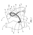
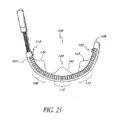
図1を参照すると、好ましい実施態様の僧帽弁弁輪形成および心臓補強デバイス40が内部に配置された心臓10の略図が示されている。心臓10は、一般に、上大静脈14および下大静脈16に連通する右心房12を含む。左心室18は、左心耳20の下に配置される。冠状脈管構造の関連部分は、心門24から冠状静脈洞および大心臓静脈28の接合部26に延在する冠状静脈洞22を備える。大心臓静脈28と中心臓静脈30との間には、先行技術で周知のとおり、吻合接続部29が存在する。
Referring to FIG. 1, there is shown a schematic diagram of a
僧帽弁弁輪形成および心臓補強デバイス40の一実施態様は、全体として冠状静脈洞22内に示されている。特に、デバイス40は、近位端42から遠位端44に延在する。近位端42は、心房間隔膜46の後側に隣接して存在する。デバイス40の中間部分48は、冠状静脈洞22内に位置する。デバイス40の遷移部分50は、冠状静脈洞22および大心臓静脈28の接合部26に存在する。デバイス40の遠位端44は、大心臓静脈28内に差し込まれる。
One embodiment of the mitral annuloplasty and
遷移領域50は、大心臓静脈28の近位の部分に存在するように設計される。この領域は、冠状静脈洞22により画定される平面から偏向することにより、固定装置52として役立ち、デバイス40が、緊張が加わった時に、冠状静脈洞22から滑り出るのを防止する。固定装置52のこの実施態様は、好ましくは、非常に弛緩性かつ可撓性であり、その結果、大心臓静脈壁または冠状静脈系のその他の面により、デバイス40が侵食される危険性を最小限にする。デバイス40の近位端42は、冠状静脈洞22の心門24の外側に存在し、心房間隔膜46の後側に隣接して固定するように、望ましくは曲線状に上方に向く。有利には、図示のデバイス40の近位端42は、半円形の形状および楕円形のプロファイルであり、縁部は隣接組織の侵食を促進しない。
The
デバイス40の遠位の延在部分に代わる固定装置52として、多様な構造のどれでも提供できる。一般に、展開デバイス40は、アーチ形経路の内径に沿って冠状静脈洞22の壁に接触する。したがって、展開デバイス40の凹面上の組織接触表面54には、多様な摩擦表面構造の何れか、たとえば複数の横断隆起、歯もしくはその他の突出部、または摩擦を強化するための改質表面テクスチャを設ける。別法によると、羽枝などの組織係合または穿孔構造は、以下に説明するとおり、表面54上に設けられ、冠状静脈洞22の壁に係合してデバイス40の移動に抵抗する。
Any of a variety of structures can be provided as a
固定装置などの構造を使用すると、特定の用途にある程度の利益をもたらすが、本明細書に図示して説明する実施態様は、特に、こうした積極的な組織係合を行わなくとも動作するため、ある態様では特に有用であると考えられる。当業者には、本発明の開示により、本発明の実施態様が独立デバイスの操作および形状制御を提供し、十分な力を僧帽弁に与えることを可能にし、リモデリングプロセスのために、洞内で組織に穿孔して組織を把持するという、おそらく有害な作用を必要としないことが明白である。ある点では、羽枝のない構造の個々の作用は、緊張方向および緩和方向の両方で調節することを可能にし、組織を著しく損傷または侵食する危険性は減少する。別の点では、少なくとも特定の実施態様によるデバイス40は、形状の修正範囲全体でその長さを有利に維持するが、洞および隣接する弁輪はリモデリング力が加わった寸法を減少させる。さらに他の点では、組織穿孔および把持固定装置の独立する動作および動作しないことにより、このデバイスは、最初に洞内に埋め込んだ後に、たとえば合併症が生じた場合、または患者を外科手術に回すなどのために、一時的な治療処置を施すために意図される用途で、患者から除去することができる。さらにこの点に関して、埋め込みに対して生体内で観察される反応に応じて、適切なデバイスを発見する前に、様々な形状およびサイズのデバイスが特定の患者に必要である。
Although the use of a structure such as a fixation device provides some benefit for certain applications, the embodiments illustrated and described herein operate in particular without such positive tissue engagement, Certain embodiments may be particularly useful. For those skilled in the art, the disclosure of the present invention allows embodiments of the present invention to provide independent device operation and shape control, allowing sufficient force to be applied to the mitral valve, and for the remodeling process, Obviously, it does not require the detrimental effect of perforating and grasping tissue within it. In some respects, the individual effects of unfeathered structures can be adjusted in both tension and relaxation directions, reducing the risk of significant tissue damage or erosion. In other respects, the
僧帽弁弁輪形成および心臓補強デバイス40の特定の寸法、構造の詳細および材料は、当業者が本明細書の開示事項を考慮すると理解するように、大きく異なって良い。たとえば、異なる解剖学上のサイズおよび構成に適応させるために、寸法調節を行うことができる。材料および構造の詳細は、異なる緊張機構およびその他の考慮事項に適応するように変更することができる。
The specific dimensions, structural details and materials of the mitral annuloplasty and
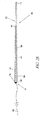
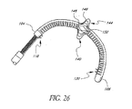
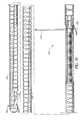
一般に、デバイス40は、近位端42から遠位端44までの全体的な長さを画定する。好ましくは、この長さは、固定装置52が大心臓静脈28内に差し込まれる本体66の遠位の延在部分を備える図2に示すような実施態様では、約2cm〜約10cmの範囲内である。デバイス40の一実施態様は、長さが約8cmの長形の可撓性本体66を備える。こうした実施態様では、本体66は、以下で説明するとおり、本体66内の緊張要素に力が加わった場合、単一平面内で屈曲するように楕円形の断面で良い。デバイス40は、遠位にテーパが付き、丸みのある断面に遷移する。
In general,
図2A〜Bを参照すると、内部にワイヤなどの形成要素56を有するデバイスの一実施態様が示されている。形成要素56の操作により、このデバイスは、血管系内に経皮的に挿入して、冠状静脈洞内にナビゲートすることを可能にする可撓性の方向から(図2B)、僧帽弁輪の少なくとも1部分を圧縮するアーチ形構成(図2A)に移動することが可能である。デバイス40は、特定の構造に応じて本体66に対する形成要素の軸方向近位の後退、または遠位の前進により、第1の可撓性構成から第2のアーチ形構成に前進する。
2A-B, one embodiment of a device having a forming
一般に、デバイス40は、近位端42から少なくとも接続機構60の位置まで延在する可撓性支持体58を備える。支持体58は、本体66の一部分であるか、以下で説明するように別個の構成要素で良い。支持体58は一定の長さを有し、実質的に軸方向に非圧縮性かつ非拡張性である。したがって、支持体58の近位端に対する形成要素56の近位の軸方向後退により、望ましくは、支持体58は第1方向に偏向し、本体66の長手方向軸を横断する軸の周囲で本体66を屈曲させる。支持体58に対する形成要素56の遠位の軸方向前進により、支持体58は第2方向に側方に偏向し、本体66は、支持体58の固有の弾力性によりまっすぐになる。基本的なステアリング構成は多くの形態で実施され、当業者は、所望の寸法および臨床性能に応じて本体66の特定の構造に適応するように、最適化することができる。
Generally, the
形成要素56は、近位端42からデバイス40を通って接続機構60の位置まで延在する。接続機構60の位置では、形成要素56は、支持体58に機械的に結合され、好ましくは直接結合される。別法によると、接続機構のその他の適切な方法を使用して良い。形成要素56の近位の延在部分64は、デバイス40の近位端42から、たとえばアパーチャ62を通って延在する。アパーチャ62を通る形成要素の近位の後退により、デバイス40は、埋め込みまたは供給方向から屈曲し、埋め込み時に冠状脈管構造を形成またはリモデリング方向にナビゲートされて、冠状静脈洞22および隣接構造を圧縮および拘束する。
Forming
デバイス40は、形成、リモデリング方位では、上記のとおり、僧帽弁輪に対して圧縮力を提供することが好ましい。これは、望ましくは、デバイスをアーチ形構成に形成することにより達成される。一般に、形成されたデバイスが適合する一定の半径の最も良く適合する曲線は、約1.0cm〜約2.0cmの範囲内の半径を有する。形成要素は、多様な材料および構造、たとえばポリマーもしくは金属ワイヤもしくはストランド、多線維編組もしくは織ライン、金属もしくはポリマーリボン、またはデバイス40を冠状静脈洞22内で緊張状態で保持することが可能なその他の構造の何れかを含む。
デバイス40は支持体58をさらに備え、支持体58は、デバイス40の本体66または内部に配置された別個の要素である。支持体58が、デバイス40内に含まれる別個の要素である実施態様では、支持体58は、多様なほぼ軸方向に非圧縮性の要素、たとえば金属もしくはポリマーワイヤもしくは支柱、リボン、または「最低位置にある」(たとえば、完全に圧縮された)ばねの何れかを含み、これらは、側方の屈曲を促進するが、形成要素56の近位の後退後の軸方向圧縮を防止する。ステンレス鋼、ニチノール、またはその他の公知の材料を含む金属リボンは、形成方位では、デバイス40の湾曲平面に影響を及ぼす能力により、特定の実施態様では望ましい。
現在図示している実施態様では、形成要素の近位の延在部分64は、展開カテーテルの長さ全体に近位に、展開手順時に患者の体外に留まる制御装置または自由端まで延在する。デバイス40を冠状静脈洞内に配置した後、近位の延在部分64上における近位の牽引は、好ましい実施態様の使用方法に関連して以下で説明するように、デバイス40を冠状静脈洞内の形成方位状に再構成する。十分な緊張を冠状静脈洞22上に配置した後、形成要素56は、好ましくはデバイス40に対して一定の軸方向位置にロックされ、形成要素56がアパーチャ62を通って遠位に移動するのに抵抗する。様々な適切なロック構成を設けることができる。好ましくは、ロック70は近位端42上または近位端42付近に設けられ、特にアパーチャ62に、またはアパーチャ62周囲に設けられる。ロックは、当業者が本明細書を考慮すると明白になるように、任意の様々な構造、たとえば縫合結紮、ロッククランプもしくはリング、締り嵌め、ラチェットおよび爪構造、ねじ付き係合、凝縮結合、または圧縮装着から構成される。
In the presently illustrated embodiment, the
ロック70(本明細書の実施態様の何れかにおける)は、最初に離脱させて、その結果、形成要素56はアパーチャ62を通って自由に後退または前進することができ、その際、医師がデバイス40の緊張状態を調節する。所望の緊張状態が達成されると、ロック70が作動して、ロックの構造に応じた方法で形成要素に係合する。別法によると、ロック70は、たとえばラチェットまたはカム構造により係合構成に付勢され、その結果、形成要素は近位にのみ後退することが可能である。しかし、好ましくは、ロックは、形成要素を解除することを可能にし、その結果、瞬間的に過度に緊張した場合、医師がデバイス40の緊張状態を解除することが可能である。
The lock 70 (in any of the embodiments herein) is first disengaged so that the forming
形成要素56および58は、以下に記載する管状本体の有無に関わらず、ePTFE、またはDACRONなどのポリエステル布帛、または形成要素56上に巻かれるか、または縫合されて、最終デバイス40を形成するその他の管状ジャケットにより囲まれる。その他の代案として、形成要素56、および存在する場合は、支持体58を含む部分組立体は、押出しなどにより形成される適切な長さの管内に配置される。管は、遠位端44における縮小直径まで引き下ろされる。押出し後のその他のステップは、所望の断面構成を形成するために使用される。本発明の製造技術は、当業者が本明細書の開示事項を考慮すると明白になるであろう。
Forming
デバイス40には、所望の臨床性能に応じて多様なその他の何らかの特徴を追加することができる。たとえば、本体66の外面には、商標PARALENEで市販されているポリ−パラキシレン、PTFEまたはその他など、潤滑性を改善するための様々なコーティング、ヘパリンまたはその他の抗血栓剤、表面を軟化させ、血管脈管内膜などに対する外傷の危険性を減少させるためのシリコーン、ネオプレン、ラテックスまたはその他などのエラストマーが提供される。粘着性強化表面、たとえばePTFEパッチまたはジャケットは、細胞の内殖を促進して長期間固定するために形成される。さらに、展開システムの構造に応じて、本体66には、本体66を軸方向に貫通して延在するガイドワイヤの内腔が形成され、本体66は、治療位置に配置する時にガイドワイヤ上を遠位に前進することができる。
Various other features may be added to the
デバイス40は、ポートを通して、別の外科手術手順と組み合わせるなど、直接的な外科手術(たとえば、胸骨切開を行うかどうかに関わらず、開胸術)による接近、または経皮的もしくは外科手術的切断による静脈系に対する接近により冠状静脈洞22内に埋め込まれる。好ましくは、デバイス40は、内部の頚静脈、鎖骨下動脈または大腿静脈の1つにおける経皮的接近によるなど、経管的手順で埋め込まれる。
The
図3〜図8Bは、例示的なデバイス組立体200を示す。一般に、図3は、補綴物またはインプラント250に係合する供給組立体210を備える組立体の全体図である。本明細書で説明する類似の全体的な供給システムおよび方法によると、補綴物250は、供給組立体210を操作することにより、第1条件および形状で、少なくとも部分的に血管内に供給されるように構成される。目標血管の所望の領域では、補綴物250は、隣接する組織構造に影響を与えるように、血管内の第2状態および形状に応じて調節されるように構成される。また、本明細書中に記載するとおり、特に有益なモードのこうした手術は、僧帽弁輪に影響を与えるために、より詳細には、輪の形状に影響を与えて僧帽弁の逆流を減少させるために、補綴物250を冠状静脈洞内に配置する。
3-8B illustrate an
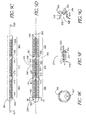
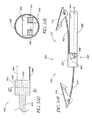
図4〜図7は、デバイス組立体200の近位の面、特に、好ましくは管状である外側部材215と、好ましくは内側部材225を収容するサイズである内腔216とを含む供給組立体210の様々な詳細を示す。図示の変形例における内側部材225はほぼ管状であり、好ましくは、患者の体外において、内側部材225に対して近位に回転力を与えることにより、内腔216内で実質的に自由に回転する。図示の実施例によると、この回転力は、供給組立体210の近位端部分211に結合された近位のハブ組立体201上に設けられるサムホイール205を解して内側部材225に加えられる。サムホイール205は、ハブ組立体201内の内側部材225に回転可能に結合され、こうした回転結合は、当業者には明白であると思われる多くの修正方法により達成される。
FIGS. 4-7 illustrate a
内側部材225の回転は、以下のとおり、補綴物250の近位端部分252内に係合する回転カップラーの回転に伝達される。内側部材225は、その遠位端部分上にアパーチャ228を有し、この遠位端部分は、内側部材225と雌対応部分との間の嵌合キー界面の雌対応部分を形成し、この雄対応部分は、やはり補綴物250の近位端部分252内に回転可能に係合する回転カップラー280の形成近位端281により提供することが望ましい。内側部材225と回転カップラー280との間のキーによる取付けは、回転力を回転カップラー280に伝達することを可能にする。こうしたキー結合の解除可能な軸方向係合を維持するため、フィラメント240などの可撓性部材をアパーチャ283から回転カップラー280の近位端281にループ状に通し、両方のフィラメント端部242および244は、内側部材225を通ってカテーテルの近位端の位置に近位に延在する。フィラメント240は、一般に、遠位のキー結合の係合を維持するのに十分な緊張状態を保つが、フィラメントが単に存在することにより、キー結合の雄/雌界面に十分に厳密な許容差が存在する場合、解離を妨げる。
The rotation of the
回転カップラー280は、近位のポートまたはアパーチャ251を通って補綴物250の近位端部分内に回転可能に係合し、回転カップラーは、補綴物250内で回転するか、または補綴物250に対して回転するように構成される。こうした相対的回転は、以下のとおり、補綴物250の偏向を現位置で強制的に第2構成の所望の形状にするように変換される。
The
回転結合の一態様によると、補綴物250は、好ましくは回転に抵抗するように保持され、回転カップラー280は補綴物250内で回転する。これは、補綴物250が冠状静脈洞などの所望の血管内に供給された後、単に周囲組織の摩擦力により達成される。もう1つの実施例によると、これは、補綴物250の外側部材215と近位端部分252との間に摩擦嵌合などの解除可能な界面を提供することにより達成され、外側部材215と補綴物250との摩擦係合は比較的一定の位置に保持され、内側部材225と回転カップラー280とが回転する。この実施態様を図4に示す。摩擦嵌合界面のほかに、またはその代わりに、図6〜図7に示すようにキー界面を使用する。この方法によると、補綴物250の近位端252上に形成された近位の嵌合部253は、雄対応部分として、外側部材215の遠位端212上にある形成アパーチャまたは嵌合部内に嵌合するように構成される。このキー界面は、内側部材225および回転カップラー280に関して上記で述べた方法に類似する方法で部在間の回転結合を可能にし、部材を軸方向に離脱させると、摩擦が減少して比較的解除可能な結合が可能である。
According to one aspect of the rotational coupling, the
回転カップラー280からの回転力は、図8A〜Bに示す一実施例による補綴物250上の偏向力に変換される。補綴物250は、内腔262を有するほぼ管状の壁または本体260を備え、補綴物250の近位端部分252から遠位端部分254に延在する。近位端部分252に沿って、内腔262と連通する溝付き内側ボア264を有するナットの嵌め合い263が固定される。この特定の実施態様の他に、回転カップラー280は外側の螺旋状ねじ部285がボア内腔の内面の嵌合ねじ部内に係合するねじ部材であり、ねじ部285の遠位の部分は、内腔262内に遠位に延在し、成形近位端部分282に類似すると共に、アパーチャ288も有する第2キー嵌合部287で終了する。回転カップラー280の近位端と同様、もう1つの可撓性部材またはフィラメント290はアパーチャ288からループ状に通され、2本のアームは、292、294は、アパーチャ288から補綴物250の遠位端部分254に沿って接続点まで遠位に延在する。ナットの嵌め合い263は、外側管状本体260に関連して固定され、管状本体は、上記と同様に比較的定位置に保持され、回転カップラー280の回転は、カップラー280を本体260に対して近位に移動させる。回転カップラー280のこうした近位の軸方向平行移動は、フィラメント290上に緊張を与え、その結果、遠位の接続機構により本体260上に緊張を与える。外側本体260上のこうした緊張は、本体260を偏向させる。したがって、回転力は張力に変換され、その結果、デバイス250の長手方向軸Lに対する本体260の半径方向偏向を生じる。つまり、本体260は、長手方向軸Lを横断する軸の周囲で偏向する。図8B参照。
The rotational force from the
上記の強制的な偏向は、規定の方法でこうした力に反応する、つまり降伏するように設計された補綴物250内に複合構造を設けることにより、特定の平面内で制御することができる。図示の特定の実施態様では、比較的非圧縮性の支柱支持体または脊柱部材270が、管状本体260の内腔262内に設けられる。この脊柱部材270は、外側管状本体260のみの材料に比べて剛性であり、軸方向の力、特に張力により耐える。したがって、補綴物250の周囲に沿った1ヵ所の半径方向位置のみに沿って脊柱部材270を設けると、デバイス250上にバイアスが生成され、脊柱270から離れてデバイス250のより圧縮性の領域方向に偏向させる。こうした複合構造は、積層構造、埋め込みワイヤ強化壁構造などの複合構造をさらに備えるか、またはデバイスの材料の変形を設計することにより、たとえば別の領域に対して、外側管状本体260に沿ったある位置の材料を薄くするか、厚くするか、硬化するか、または軟化して、本体260を所望の位置で偏向させることにより達成される。
The forced deflection described above can be controlled in a particular plane by providing a composite structure within the
本明細書に記載するその他の制御可能な実施態様により達成されるように、本発明の実施態様による偏向は、医療介護提供者の要望に応じて調節され、曲率半径Rを締めるか、または曲率半径Rを開放することにより何れの方向にも調節可能である。図8B参照。しかし、この特定の実施態様によると、偏向の緊張と緩和との選択肢の調節可能性は、回転力伝達システムに配置される回転の方向および範囲によって決まる。 As achieved by the other controllable embodiments described herein, the deflection according to embodiments of the present invention is adjusted according to the needs of the health care provider and tightens the radius of curvature R or curvature. It can be adjusted in either direction by opening the radius R. See FIG. 8B. However, according to this particular embodiment, the adjustability of the deflection tension and relaxation options depends on the direction and extent of rotation arranged in the rotational force transmission system.
所望の偏向が達成され、所望の治療結果が観察されたら、補綴物250は、内側部材225と回転カップラー280との間のキー結合においてトルクまたは回転力伝達システムを切断することにより、供給組立体210から取り外すことができる。これは、最初に、近位のフィラメント240の少なくとも一方のアーム242、244を解除し、他方のアームを引き出し、それによりフィラメント240をアパーチャ283から通し(図8Bの肉太の矢印に示すように)、アパーチャ283から完全に引き抜くことにより行われる。その結果、内側部材225は、回転カップラー280から近位に引き抜かれて補綴物250を分離し、それにより補綴物250を埋め込む。
Once the desired deflection has been achieved and the desired treatment result has been observed, the
別法によると、本明細書に記載するその他の調節可能な偏向システムと同様、補綴物は、一時的な期間だけ(ただし、入院時に延長される場合がある)その治療状態に保持され、その間に、その他の治療、たとえば弁輪形成、弁外科手術、心臓移植などを実施するまで、一時的に改善された状態で患者を渡すなどを目的として僧帽弁逆流を最低限にする。こうした別法による一時的な設定では、適切な時に、偏向して収縮した補綴物を弁の周囲に締め付けた位置から逆に開放状態に調節し、次に、供給組立体がまだ補綴物に係合している全体のシステムを引き抜くことにより、埋め込まずに引き抜いた。さらに、こうした一時的な補綴物は、本明細書に記載する離脱機構を取り外すように修正し、より単純で低コストのデバイスを提供することができる。 Alternatively, like the other adjustable deflection systems described herein, the prosthesis is held in its treatment state for a temporary period (but may be extended upon admission), while In addition, mitral regurgitation is minimized for the purpose of delivering the patient in a temporarily improved state until other treatments such as annuloplasty, valve surgery, heart transplantation, etc. are performed. These alternative temporary settings, when appropriate, adjust the deflected and contracted prosthesis back to the open position from the clamped position around the valve, and then the delivery assembly is still engaged with the prosthesis. By pulling out the combined system, it was pulled out without being embedded. Further, such temporary prostheses can be modified to remove the detachment mechanism described herein to provide a simpler and lower cost device.
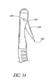
デバイス組立体200は、図3および図8A〜Bにも、ガイドワイヤの内腔265を有する遠位のガイドワイヤ追跡部材を備えているように示されており、この内腔265は、ガイドワイヤ230に摺動可能に係合するように構成され、冠状静脈洞22内など、望ましい血管位置内に経皮的経管的手順で配置される。図示の特定のガイドワイヤ内腔は、「迅速交換」または「モノレール」構造として補綴物250の遠位の面内で一体であり、生体内におけるガイドワイヤおよびカテーテルの比較的独立した運動を可能にする。さらに、この構造は、「オーバー・ザ・ワイヤ」システムの実施例に見られるように、デバイス組立体200全体を同軸状に通って進行する。図示のタイプは、有利なことに、補綴物250を取り外し式に係合させることが可能であり、好ましくは、これは、任意のガイドワイヤ230を遠位の内腔265から引き抜いた後に行う。
The
前記の各々の埋め込み方法では、医師は、好ましくは、インプラントを締めつけるステップで、逆流の程度を監視する。僧帽弁閉鎖不全の減少は望ましいが、逆流は、適度(2+未満)を多少下回るように減少させることが好ましい。いかなる場合にも、少なくとも1等級の減少を達成することが好ましい。一方、インプラント250の再構成は、僧帽弁狭窄を生じるのに十分な程度まで、または血流力学的な流れの制限が有意になる程度まで行わないことが望ましい。
In each of the above implantation methods, the physician preferably monitors the degree of reflux in the step of tightening the implant. Although a reduction in mitral regurgitation is desirable, it is preferred that the reflux be reduced somewhat below moderate (less than 2+). In any case, it is preferable to achieve at least one grade reduction. On the other hand, it is desirable not to reconstruct the
したがって、埋め込みは、埋め込みおよび/または再構成ステップ時に、かつ好ましくはこれらのステップの前後にも、僧帽弁閉鎖不全の程度を監視するステップをさらに含むことが好ましい。僧帽弁閉鎖不全の程度は、先行技術で理解されているように、僧帽弁輪および/または左心室の段階的制限ステップ時に、ステップ経食堂心エコー図法、心臓内エコー心拍動記録法、左心室内で放射線造影(LVグラム)を使用するX線透視検査、または左心房もしくは肺毛細血管楔入圧の痕跡などにより監視する。医師が、特定の患者の逆流の十分な減少が達成されたと判断したら、デバイス250をロックして、供給組立体210をデバイス250から分離し、患者から取り外す。
Accordingly, the implantation preferably further includes monitoring the degree of mitral regurgitation during the implantation and / or reconfiguration steps and preferably also before and after these steps. The degree of mitral regurgitation, as understood in the prior art, during step-limiting steps of the mitral annulus and / or left ventricle, step transesophageal echocardiography, intracardiac echocardiography, Monitor by fluoroscopy using radiography (LV grams) in the left ventricle, or by evidence of left atrial or pulmonary capillary wedge pressure. Once the physician determines that a sufficient reduction in the backflow of a particular patient has been achieved, the
この方法は、冠状静脈洞22および/またはその他の課静脈を測定するステップと、適切なサイズのインプラント250を様々なサイズのインプラントの配列から選択するステップとをさらに含む。こうしたパラメーターとしては、洞の円弧の直径、長さまたは曲率半径が挙げられる。したがって、インプラント250は、サイズの段階的配列で提供され、各々の患者に最適なサイズを選択できることが好ましい。冠状静脈洞22またはその他の静脈のサイズは、エコー心拍曲線、MRI、CTスキャン、または先行技術で周知されている血管造影法を使用して測定することができる。さらに、当業者には明白であるように、冠状静脈洞22のパラメーターの測定は、たとえば僧帽弁の直径などの僧帽弁およびその輪の特定のパラメーターの指標を提供し、この場合、冠状静脈洞のパラメーターまたは僧帽弁のパラメーターはどちらも、適切な寸法のデバイス250をキットから選択するために必要な情報を提供する。
The method further includes measuring
こうした僧帽弁のパラメーターは、さらに、上記の様々な方法により直接測定して、適切なデバイス250を選択するために使用する値を生成することができる。本明細書に記載するように、解剖学的特徴のパラメーターを測定した後、その値は、個々の測定器具の精度に応じて概算され、これは、特殊な医療技術を持たないか、または訓練を受けていない人が、この概算値を武器にすると、適切な医療デバイス250をキットから選択することができるように意図されている。たとえば、キットの各デバイス250のパッケージには、キットのその他のデバイスに対するデバイス250に固有の個々の寸法が指示され、測定された解剖学的パラメーターの概算値を単純に比較することができる。
These mitral valve parameters can also be directly measured by the various methods described above to generate values that are used to select the
本明細書に記載されている様々な実施態様は、洞22内のデバイス250の長さを実質的に変更せずに、冠状静脈洞22を操作して僧帽弁輪を縮小するように構成される。その結果、洞の長さおよび/または輪の直径をリモデリング時に、補綴デバイス250の半径方向偏向から縮小する場合、冠状静脈洞22に沿ったデバイス250であって、僧帽弁輪の周方向にあるデバイス250の有効的な調達を増加することにより利益が得られる。これは、デバイスのキット内のデバイス250の寸法は、測定する解剖学的パラメーターの概算値に直接対応しないことも意味する。たとえば、測定したデバイスパラメーターの対照値は、デバイス250の処置時に洞22が短縮する可能性により、概算された冠状静脈洞22より短い場合がある。あるいは、解剖学的パラメーターは、治療から予測されるかまたは所望の最終結果に基づく初期値から概算され、手順上関連するこうした値は、適切なデバイスを選択するために使用される(たとえば、生体内で使用する場合、洞または僧帽弁の直径の概算最終長さを、リモデリング構成のデバイスの既知の寸法と比較する)。
Various embodiments described herein are configured to manipulate the
本発明のさらに他の態様として、インプラント250は、好ましくは、鬱血性心不全を治療するための適切な薬剤療法と結合する。残余逆流およびその他の血行力学機能は、本発明のインプラントの埋込み後に測定することが好ましい。心臓の投薬は、患者に対する現行の薬物療法を処方する時に、逆流の減少および/または左心室容積の減少を考慮に入れて調節することが好ましい。
As yet another aspect of the present invention, the
さらに、本発明は、外科手術による比較的従来型の弁輪形成術または弁置換に関連する細胞間橋体系として、僧帽弁リモデリングのために洞22内における一時的使用を意図する。デバイス250のこうした結合システム、およびさらに薬剤体系と結合する個々の使用方法は、有害な僧帽弁逆流を伴う患者を管理する点で、非常に有益な結果を提供することが可能な全体的な治療体系を提供する。
In addition, the present invention contemplates temporary use in the
本明細書に記載するすべての実施態様には、外側に対向して導電性で、軸方向に延在する1個または複数の導電性ストリップまたは環状帯が設けられ、デバイス40が心臓調整またはその他の診断もしくは治療上の心臓電極としてさらに機能することを可能にする。1個または複数の導電性帯は、デバイス40から離れて延在する1個または複数の導電体により心臓調整源または診断器具と電気的に結合する。この導電体は、多様な電気的心臓律動管理デバイスの何れかに電気的に接続され、こうしたデバイスは、先行技術で十分に公知である。
All embodiments described herein are provided with one or more conductive strips or annular bands that are electrically conductive opposite the outside and extend axially, so that the
図9Aおよび図9Bの一実施態様に示すように、冠状静脈洞では、長形の本体320は、第1の埋め込み(可撓性)構成から、僧帽弁輪をリモデリングするように構成される形状を有する第2の(比較的剛性)リモデリング構成に調節されるように構成される。図9Bに示す実施態様によると、この形状は、全体として、たとえば弁の周囲の一部分上まで少なくとも部分的に把握して、直径に減少力を与えるように示されている円弧形状により、輪上に外力を与えて、少なくとも1本の横断方向軸に沿った直径を縮小させるように構成される。また、仮想図に示すように、円弧形は度が異なる形態を取る場合があり、その他の非常に有益な用途では、異なる度間で、または連続する度の範囲全体で制御可能かつ選択可能である。図示の実施態様によるこうした制御可能性は、図9Bに示して、以下で詳細に説明するように、中韓の偏向可能部分360、370間でも選択可能である。
As shown in one embodiment of FIGS. 9A and 9B, in the coronary sinus, the
長形の本体320は、長形の本体320の偏向可能部分360、370の長さに沿って連続的に延在する管状壁325から構築される。列状または複数の別個の不連続なスロットまたは空隙330は壁325内に形成され、各々の空隙330は、長手方向軸を横断する長形を有する。空隙330は、管状壁325の一方の側部の軸方向を短縮し、図9Bに示す曲率を可能にする。
The
さらに、図9A〜Fの特定の実施態様を参照すると、横断方向空隙330は、中心の溝形領域であって、隣接部分332、334が長手方向軸に沿って頂点333で収束する領域を有する。こうして形成された空隙330は、少なくとも部分的に、長形の本体320の壁部にある2つの隣接する長手方向に対向する部分340、350の2つの対向する相補的に形成された表面により画定される。これらの部分340の1つは、軸方向の遠位の方向に凸状の形状を呈し、頂点333の周囲の他の部分350は、軸方向の近位の方向に凹状であることが望ましい。こうして形成された表面340、350は、凸状部分340が凹状部分350内に配置された入れ子式構成であることが好ましい。この構成では、隣接する壁部分340、350の一方のその他の部分340、350に対する側方(回転)運動は、その他の隣接部分340、350との機械的界面により実質的に防止される。長形の本体320の隣接部分340、350の相対的な入れ子状態は、第1平面に沿った半径方向偏向に機械的干渉を提供し、軸方向の屈曲力が与えられた後、第2平面に沿った長形の本体320の偏向を実質的に隔離する。
Further, referring to the particular embodiment of FIGS. 9A-F, the
図9Dは、図を単純化して分かりやすくするために、溝付き空隙330を平面図に示す。しかし、図9Cに示すように、かつ図9Eを参照すると、これらの横断方向空隙330(および、ここに詳細に説明するV形部分のほぼ全体)は、長形の本体320の周囲の少なくとも約180度に広がる。好ましくは、横断方向空隙330は、長形の本体320の周囲の約300度を超えて広がり、さらに好ましくは、空隙は、周囲の約300度〜約315度の間に広がる。こうした溝付き空隙を壁325の周囲に同様に整列させて配置することにより、一体および連続する背骨または脊柱327は、長形の本体320の長さに沿って軸方向に走る壁325に沿って形成される。空隙330および脊柱327のこうした全体的な配置は、空隙のパターンおよび軸方向の完全性、残りの壁構造により、所望の組合せの屈曲可能性を提供することが観察された。
FIG. 9D shows the
図9A〜Fに示すインプラント300の長形の本体320は、一般に、長手方向の軸に沿って3つの偏向可能部分360、370、380と、非偏向可能部分310とを有する。偏向可能な各々の部分360、370、380は、上記のように一群の空隙330を有し、患者の体外から力を加え、長形の本体320を冠状静脈洞内に配置することにより、第1構成と第2構成との間で個々に偏向可能であるようになっている。特に、3個の形成要素365、375、385は、3個の偏向可能部分360、370、380にそれぞれ結合し、第1構成と第2構成との間の当該部分を再賦形するために、当該部分に偏向力を与える。各々の形成要素365、375、385は、長形の本体320を冠状静脈洞内に配置して、個々に結合された偏向可能部分360、370、380に偏向力を与えるように手動で操作する時に、患者の身体から外側に延在するように構成する。結合されたこれらの部分の各々の偏向は、第2構成の長形の本体320の全体的な形状に備える。
The
形成要素365、375、385は、それぞれ接続機構361、371、381の特有の長手方向に離れた位置において長形の本体320に取り付けられ、各々の接続機構は、それぞれ結合された偏向可能な部分360、370、380の遠位端に存在するか、または遠位端より遠位に存在する。有益な1つの用途は、本体320に対する形成部材365、375、385の接続機構に関して示されており、接続機構361、371、381の各々の位置は2個の軸方向に離間配置されたアパーチャを有し、これらのアパーチャは、接続機構361の位置では、近位および遠位のアパーチャ362、363として示され、接続機構の位置371では、近位および遠位のアパーチャ372、373として示され、接続機構381の位置では、近位および遠位のアパーチャ382、383として示されている。図9Fの接続機構371の位置に示すように、形成要素375の賦形された遠位端377は、遠位のアパーチャ373内に着座するサイズに構成され、固定剤374、たとえば接着剤、溶融結合剤またははんだなどにより、アパーチャ373内に固定される。個々の形成要素365、375、385はすべて、アパーチャを通して壁に接合される。形成要素375は、遠位のアパーチャ373から近位に延在し、近位のアパーチャ372から導入される追加の固定剤374により、さらに壁325に固定される。さらに、遠位端37は、図9Fの想像図に示すように、近位の軸方向力が加わった時に、接続機構に機械的固定手段を提供するようにも賦形される。
Forming
有用であることが観察された特定の一実施態様によると、この接続機構の実施態様のためのアパーチャは、一般に、直径約0.020インチ〜約0.022インチであり、長手方向の感覚は類似しており、着座した形成要素の遠位端は、直径約0.012〜約0.014インチである。この実施態様のほかに、壁325は、一般に、管状のステンレス鋼壁またはハイポチューブから構成され、その内部には、図9Dに示して説明されているか、または本明細書のどこかに説明されているパターンに類似するパターンに従って、複数の溝付き空隙330が形成される。この実施態様のほかに、図9Dに示して説明する溝は、レーザ切断により下にあるステンレスチューブ内に形成したが、その他の十分に公知の技術、たとえば手動の把持、機械的切断、フォトリソグラフィなどを代わりに使用して良い。
According to one particular embodiment that has been observed to be useful, the aperture for this connection mechanism embodiment is typically about 0.020 inches to about 0.022 inches in diameter, and the longitudinal feel is Similar, the distal end of the seated forming element is about 0.012 to about 0.014 inches in diameter. In addition to this embodiment, the
上記のとおり、形成要素365、375、385から加わる力は、一般に、長形の本体320、および偏向可能部分の近位にある長形の本体320に沿った近位の位置(図示しない)に対する接続機構の位置361、371、381の軸方向の力である。図示の特定の実施態様によると、この力は、一般に、接続機構の位置361、371、381と、長形の本体320の近位端部分との間にある。長形の本体320は、一般に、保持デバイス(図示しない)による強制的な偏向時に、偏向可能部分に対する長形の本体320の近位端部分を実質的に固定するように保持され、その結果、軸方向の力は、これらの部分の間に現位置で印加される。偏向力を偏向可能部分360、370、380に印加するための形成要素320の近位の操作は、上記のとおり軸方向だが、別の点では回転力で良い。
As noted above, the forces applied from the forming
各々の偏向可能部分360、370、380は実質的に軸方向に剛性であり、長手方向軸に対して非圧縮性であり、したがって、長形の本体320の全体的な軸方向長さは、第1構成と第2構成との間で実質的に一定を保つ。しかし、各々の偏向可能部分は、長手方向軸を横断する半径方向軸に沿って比較的可撓性であり、その結果、偏向可能部分は、長形の本体の遠位の位置であって、偏向可能部分の遠位端、またはこの遠位端より遠位の位置と、偏向可能部分の近位にある長形の本体320に沿った近位の位置との間に軸方向の力が印加されると、半径方向に屈曲するように構成される。ある点では、長形の本体320は、各々の偏向可能部分360、370、380と、長形の本体320の近位端部分との間で軸方向に非圧縮性または非拡張性であり、各々の偏向可能部分360、370、380は、長形の本体320の遠位の位置と、長形の本体320の近位端部分である近位の位置との間にそれぞれ圧縮または緊張の軸方向力が印加された後、半径方向に屈曲するように構成される。
Each
また、他の点では、長形の本体320のその他の構成は、本体の近位端部分から遠位端部分までの一体かつ連続する壁325と、軸方向の圧縮力または張力に対する制御された半径方向屈曲反応との組み合わせに備える。さらに、形成された空隙330を組み込む連続的な一体の壁のほかに、またはこうした壁の代わりに、壁325は、工学的支持要素を含む工学的複合支持構造であって、印加される力の応力に対する空間的なひずみ反応を制御するように配置される支持構造も備える。空隙330のその他の適切な形状も許容可能である。
Also, in other respects, other configurations of the
図9A〜Fに示す入れ子式のVパターン(またはUパターン)の実施態様によりパターン化された空隙を図9Gに示し、この入れ子式に隣接する部分340、350は、互いに噛み合う歯344、354を有する界接表面342、352を含み、これらの歯は、半径方向に偏向したパターンで第2構成にロックするように構成される。詳細には、歯344、354の界接パターンは、ラチェット機構状に作動するように構成される。強制的な偏向の屈曲時に、内側の曲率半径に沿ってこの領域を配置することにより、圧縮力は、凸状に賦形された歯領域340を、凹状の収容領域350により形成された嵌合ウェル内により深く送り込む。この運動は、歯344、354との間に干渉を提供して部分340を偏向させ、部分350方向にさらに移動して歯354を取り除き、回復して歯344を354の後にロックする。空隙を有する領域内の隣接部分の相互作用運動は、さらに図9Gに肉太の矢印で表す。
A gap patterned according to the embodiment of the nested V-pattern (or U-pattern) shown in FIGS. 9A-F is shown in FIG. Interfacing surfaces 342, 352 having the teeth are configured to lock into the second configuration in a radially deflected pattern. Specifically, the interface pattern of
図10は、インプラント402または補綴物を冠状静脈洞またはおよびその他の治療部位に配置するように構成された医療デバイス400のその他の構成を示す。上記の実施態様と同様、医療デバイス400は、近位端にハンドル組立体404を備えるが、インプラント402は遠位端に位置する。ハンドル組立体404およびインプラント402は、長形の可撓性カテーテル本体406により接続される。望ましくは、本体406は、十分な支柱強度を有する、つまり、軸方向の圧縮に抵抗するが、本体406が半径方向に屈曲することが可能な材料の押出し品であるか、または押出し品を含む。経管的カテーテル技術、たとえばHDPEまたはPEBAXで十分に公知の多様なポリマーはどれも、本体406を形成するために使用される。しかし、その他の適切な材料を使用しても良い。一実施態様では、本体406は、約0.094インチの外径を有する。
FIG. 10 illustrates another configuration of a
図11を参照すると、複数の内腔または通路は、カテーテル本体406に沿って軸方向に延在している。図示の押出し品は、3つの内腔408、410、412および1つの比較的大きい内腔414を含む。小さい内腔408、410、412は、実質的に、本体406の円形断面の一方の半分の中に配置され、各々の円形断面は約0.024インチの内径を有する。比較的大きい内腔414は、望ましくは、小さい内腔408、410、412に対向する本体406の円形断面の実質的に半分の中に配置され、約0.044インチの直径を有する。全体として、医療デバイス400の内腔408、410および412は、制御構成要素400(たとえば、図9Aおよび図9Bの形成要素365、375、385)が、ハンドル組立体404からインプラント402まで延在し、シャフト406内で保護されることを可能にする。別法によると、所望の数のプルワイヤにより、必要に応じて、単一プルワイヤ内腔のみ、または2本プルワイヤ内腔を設けることができる。以下に詳細に記載するとおり、制御構成要素は、ハンドル組立体404の操作可能な移動を結果として得られる所望のインプラント402の移動に変換する。比較的大きい内腔414は、以下で説明するように、ドライバ436を回転可能に収容するために使用される。さらに、1つまたは複数の内腔は、冠状静脈洞の洗浄、薬剤もしくは造影剤の注入、またはその他の所望の目的を可能にするために使用される。
Referring to FIG. 11, a plurality of lumens or passages extend axially along the
図12および図13を参照すると、インプラント402がより詳細に示されている。図13は、図12の一部分の拡大図であり、供給組立体401とインプラント402との間の解除可能な接続部を示す。上記のとおり、インプラント402は、供給組立体401に取外し可能に接続されるため、供給組立体401およびインプラント402は、インプラント402が、冠状静脈洞またはその他の本体の内腔もしくは中空組織内に適切に配置されて張力を与えられた後、外れるようになっている。
Referring to FIGS. 12 and 13, the
インプラント402は本体部分416を画定し、この本体部分は、好ましくは管状の形状であり、少なくとも1つの中心内腔が本体部分を通って延在する。インプラント402の全長は、意図する治療部位および所望の臨床性能に応じて、変えることが可能である。デバイスを冠状静脈洞内に配置して、予め決められた平面を横断する僧帽弁輪の直径を縮小することを意図するある用途では、インプラント402は、一般に、約5cm〜約15cmの範囲内の長さである。殆どの成人患者の場合、約6cm〜約12cmの範囲内の軸方向長さを使用する。一実施態様では、インプラント402は、長さ約9cmであり、約15mm2以下の断面積を有する。好ましくは、インプラント402は、約10mm2以下の断面積を有する。
The
インプラントは、上記の実施態様と類似の材料、たとえばステンレス鋼、ニチノール、または埋め込みに適するその他の公知の材料から構成することができる。非外傷性の遠位の先端418は、本体部分416の遠位端上に設けられる。先端418の前端は丸みがあるので、非外傷性先端418は、患者の脈管構造を通って前進する時に、重大な組織の損傷を生じない。
The implant can be composed of materials similar to those described above, such as stainless steel, nitinol, or other known materials suitable for implantation. An atraumatic
ナット422、またはねじ付きアパーチャを内部に有するその他の構造は、本体部分416の近位端に設けられる。望ましくは、ナット422は、本体部分416に対して軸方向および回転方向に固定される。たとえば、図示の実施態様では、ナット422の外側縁部は、プルワイヤ458用のキー溝481を形成するために一方の側に平坦部464を有する円形であり、本体部分416内に適合するサイズに設けられる。ナット422は、本体部分416に熱接合され、キー溝481が形成される。当然、ナット422と本体部分416との間の相対的な回転を防止するため、その他の適切な構成を使用することができ、たとえば、その他の機械的干渉構成、固締具、はんだまたは接着剤が挙げられる。
A
インプラント402は、シャフト部分430およびヘッド部分432を有するねじ428をさらに備える。シャフト部分430は、ナット422上の内側ねじ部と嵌合する外側ねじ部を備える。したがって、本体部分416に対するねじ428の回転により、ねじ428は、本体部分416に対して軸方向に平行移動する。この相対運動は、何らかの適切な構造により、たとえばプルワイヤまたは上記のその他の形成要素の使用により、インプラント402の本体部分416を埋込み構成からリモデリング構成に移動させるために使用される。
The
ねじ428のヘッド部分432は、ヘッド部分432の近位端から軸方向に延在するキャビティなどの回転結合を含む。望ましくは、キャビティ434は、ドライバ436などの医療デバイス400の制御構成要素を収容するように賦形される。図示の実施態様では、キャビティ434は六角形であり、ドライバ436(図14)の六角形の遠位端部分438を収容するサイズに構成される。
The
雄コネクタ440は、ねじ428のヘッド部分432を含む。雄コネクタ440は、シャフト部分442およびヘッド部分444を備える。雄コネクタ440のヘッド部分444は、シャフト部分442より大きい直径を有する。通路446は、雄コネクタ440を通って軸方向に延在し、第1部分448および第2部分450を画定する。通路446の第1部分448は、雄コネクタ440のヘッド部分444に近接して位置し、雄コネクタ440のシャフト部分442に近接して位置する第2部分450の直径より大きい直径を有する。第1部分448と第2部分450との間の遷移部分は、雄コネクタ440の長手方向軸をほぼ横断して延在する。通路446の第1部分448は、好ましくは、ねじ428のヘッド部分432を収容するサイズおよび形状に構成される。望ましくは、ねじ428のヘッド部分432は、通路446の肩状部452に当接する。
環状カラー454は、ねじ428のヘッド部分432を通路446内に固定する。望ましくは、カラー454の外径は、雄コネクタ440のヘッド部分444の外径とほぼ同じである。カラー454は、雄コネクタ440の通路446の第1部分448内に、圧入構成で嵌合するサイズおよび形状に構成された内側フラン時部分456を備える。
An
上記の実施態様に類似する方法では、インプラント402は、望ましくは、インプラント402を第1の供給構成から第2のリモデリング構成に移動するように操作可能なワイヤ458を備える。ワイヤ458は、望ましくは、上記の熱接合もしくは何らかの方法、当業者が決定するその他の適切な方法により、インプラント402の遠位端に取り付ける。望ましくは、ワイヤ458の近位端は、雄コネクタ440およびカラー454に取り付けられ、好ましくは、雄コネクタ440およびカラー454に熱接合、さもなければ接着される。しかし、たとえば接着剤または機械的固締具など、その他の適切な取付け方法を使用しても良い。好ましくは雄コネクタ440およびカラー454は、プルワイヤ458の近位端に適合するスロット460を有し、その結果、ワイヤ458を平坦に配置することを可能にし、カラー454またはコネクタ440の外径を増加させない。ナット422は、平坦部464を一方の側面に備え、この平坦部は、ワイヤが隙間を通過することが可能なサイズおよび形状に構成される。
In a manner similar to the embodiment described above, the
上記のとおり、供給組立体401は、好ましくは、インプラント402に解除自在に結合することが可能である。このため、雌コネクタ466は、望ましくは、熱接合などにより、シャフト406の遠位端においてコネクタのワイヤ487に結合する。雌コネクタ466は、中空かつ実質的に円筒形であることが好ましい。雌コネクタ466の遠位端は、雄コネクタ440のシャフト部分442に係合する複数の突起または指状部分468を備える。雌コネクタ466を構成する材料の弾力性により、雌コネクタ466は雄コネクタ440を確実に把持することが可能であることが望ましい。望ましくは、指状部分468の内面は、雄コネクタ440の環状溝472に対応する環状突出物470を画定する。雌コネクタ466が雄コネクタ440に係合する場合、環状突出物470は、望ましくは環状溝472内に位置して、供給組立体401とインプラント402との間の相対的な軸方向運動を促進および防止する。
As described above, the
供給組立体401は、シャフト406の遠位端に結合されるカバー474をさらに備える。カバー474は、雌コネクタ466の指状部分468のカバーが外される第1位置から、カバー474が指状部分468の少なくとも実質的部分を覆う第2位置に軸方向に移動可能である。カバー474は、第2位置では、指状部分468の望ましくない収縮を防止して、雌コネクタ466と雄コネクタ440との間の接続の維持を促進する。
供給システム(シャフト406および雌コネクタ466を含む)と、インプラントの本体部分416との間の回転運動を防止するため、指状部分468の1つを雌コネクタ466から取り外すか、または省略して、雄コネクタ440のシャフト部分442に熱接合されるキー485内に適合する空間またはキー溝483を形成する。
To prevent rotational movement between the delivery system (including
図14は、医療デバイス400から離れたドライバ436の拡大図である。ドライバ436は、望ましくは長形のシャフトであり、近位端480から遠位端482に延在する。ドライバ436は、NiTi材料から構成されるが、その他の適切な材料を使用しても良い。ドライバ436の近位端480は、望ましくは、以下に詳細に説明するように、ハンドル組立体404に対して回転するように結合される。遠位端482は、好ましくは、六角形の断面などの非円形であり、ねじ428の対応する六角形キャビティ434に係合するサイズである。したがって、ドライバ436の回転は、ねじ428の対応する回転を生じる。ドライバ436およびねじ428の回転結合を可能にするその他の適切な構成、たとえば、嵌合構成要素として、相補的な多角形またはその他の非円形断面形状を使用しても良い。
FIG. 14 is an enlarged view of the
ドライバ436は、六角形の遠位端482の近位の側部上に配置された肩状部484を備える。好ましくは、肩状部484の直径は、六角形の遠位端482の幅(図15)より大きい。好ましい一実施態様では、肩状部484の直径は約0.032〜0.040インチであり、幅Wは約0.027インチである。したがって、肩状部484は、ドライバの六角形の遠位端482がねじ428のキャビティ434内に挿入される時に、ストップとし効果的に機能する。図示のとおり、肩状部484およびキャビティ434は、望ましくは、六角形の遠位端482がキャビティ434内に入ることを容易にするために、相補的な面取り部486、488を備える。
図示のドライバ436は、肩状部484の近位の側に1つまたは複数の縮小径部分490を備える。この部分の直径490は、肩状部464の幅、および望ましくは遠位部分490の近位端から近位端480に延在するドライバ436の主要部分492の直径の両方より小さい。好ましくは、ドライバ436の主要部分492は、約0.04インチの直径を有する。縮小径部分490は、約0.5インチ以上の長さ、および約0.027インチの直径を有する。しかし、その他の適切な寸法を使用しても良い。望ましくは、ドライバ436の縮小径部分490と主要部分492との間の遷移部分は各々、それぞれ面取り部494、495を画定し、応力の集中を有利に減少させる。
The illustrated
図16は、主に近位のハンドル500および遠位のハンドル502から成るハンドル組立体404の拡大断面である。遠位のハンドル502は、医療デバイス400を使用時に静止状態に保持するように構成され、近位のハンドル500は、遠位のハンドル502に対して回転可能であるように構成されるため、ドライバ436が回転すると、インプラント402が供給位置とリモデリング位置との間で回転する。
FIG. 16 is an enlarged cross-section of a
遠位のハンドル502は、ほぼ円筒状であり、内部キャビティ504を画定する。ねじ付きアパーチャ506は、キャビティ504から遠位のハンドル502の遠位端を通って延在し、ハンドル組立体404の長手方向軸と実質的に同軸である。近位のコネクタ508は、望ましくは、ねじ付きアパーチャ506とのねじ接続により保持され、遠位のハンドル502の遠位端から軸方向に延在する。望ましくは、遠位のハンドル502は、長手方向軸を実質的に横断するように位置すると共に、ねじ付きアパーチャ506と交差するねじ付きアパーチャ510をさらに含む。位置決めねじは、有利にはねじ付きアパーチャ506とねじ接続され、近位のコネクタ508に対して締め付けられ、遠位のハンドル502に対する近位のコネクタの望ましくない軸方向の移動を防止する。
The
近位のコネクタ508は、軸方向にコネクタを通る中心アパーチャ514を備える。中心アパーチャ514は、望ましくは、ハンドル組立体404の長手方向軸と実質的に同心であり、カテーテルシャフトを遠位のハンドルに対して一定の軸方向位置に収容する。シャフト406は、たとえば接着剤または熱接合など、任意の適切な方法で近位のコネクタ508に固定される。
図示の実施態様では、キャビティ504は、遠位のハンドル502の近位端を貫通して開放し、好ましくは、これらの間にあるねじ付き接続部を通してハンドルコネクタ516を収容する。さらに、位置決めねじ構成517は、近位のコネクタ508に関連して上記で説明する位置決めねじに類似し、望ましくは、ハンドルコネクタ516の望ましくない移動を防止するように設けられる。ハンドルコネクタ516は、近位のハンドル500と遠位のハンドル502とを接続するように構成され、これらの間の相対的回転を可能にする。ハンドルコネクタ516は、望ましくは、遠位のハンドル502から離れて近位に延在するシャフト部分を備える。円筒状通路520は、近位のハンドルを通って軸方向に延在し、ハンドルコネクタ516のシャフト部分518上に回転可能に実装されるサイズに構成される。
In the illustrated embodiment, the
好ましくは、近位のハンドル500は、遠位のハンドル502に解除自在に係合することを可能にするハンドル解除組立体522を備える。解除組立体は、望ましくは、近位のハンドル500を包囲する環状解除カラー524を備える。解除カラー524は、近位のハンドル500に対して軸方向に移動可能なサイズに構成される。複数のワイヤ固定装置526(2個を図示する)は、ハンドルコネクタ516のシャフト部分518に係合し、近位のハンドル500を遠位のハンドル502に対して一定の軸方向位置に選択的に固定する。各々のワイヤ固定装置526は、断面が円形であると共に、ボール端部528で終端する短い脚部527と、好ましくは矩形の断面である長い脚部529とを備える。望ましくは、短い脚部527および長い脚部529は、ワイヤ固定装置526が緩和位置にある場合、これらの脚部の間に約75°の角度を画定する。好ましくは、各々のワイヤ固定装置526は、多様なステンレス鋼から構成されて、全部で2個または4個以上のワイヤ固定装置526が使用される。
Preferably,
図示の実施態様では、固定装置526の長い脚部529は、近位のハンドル500の外面と、解除カラー524の内面との間、好ましくは近位のハンドル500により画定される溝530内に保持される。複数のアパーチャ532は、近位のハンドル500を通ってその近位端付近で半径方向に延在する。近位のハンドル500の外面は、溝530とアパーチャ532との間に肩状部534を画定する。肩状部534は、解除カラー524により固定された場合、ワイヤ固定装置526を機械的に偏向させて、その結果、短い脚部527と長い脚部529との間の角度は、ワイヤ固定装置526の緩和位置から増加する。解除カラー524の内面は、少なくとも解除カラー524が緩和位置にある場合、環状溝536を画定し、環状溝536は、望ましくは肩状部534をまたぐ。ワイヤ固定装置526の短い脚部527は、アパーチャ532を通って延在する。溝536は、ワイヤ固定装置526の短い脚部527と長い脚部529との間の遷移部分により画定される屈曲部538に係合し、ハンドルコネクタ516のシャフト部分518により画定される環状溝540内にボール端部528を保持する。
In the illustrated embodiment, the
図16では、解除カラー524は、第1位置または係合位置にあり、ボール端部528は、環状溝540内に保持され、近位のハンドル500が遠位のハンドル502から外れるのを防止する。解除カラー524は、近位のハンドル500の近位端方向に、第2位置または解除位置に移動可能であり、近位のハンドル500を遠位のハンドル502から取り外すことを選択的に可能にする。解除カラー524が解除位置方向に移動すると、溝536の縁部はワイヤ固定装置526に係合して短い脚部527を偏向させ、ボール端部528をハンドルコネクタ516の溝540から移動させ、その結果、近位のハンドル500を遠位のハンドル502から解除する。
In FIG. 16, the release collar 524 is in the first or engaged position and the ball end 528 is retained in the
ドライバ保持具525は、通路520の近位端内に配置され、近位のハンドル500に対して回転するようにドライバ436を固定する。したがって、ドライバ保持具525は、好ましくは、通路520(図17)の近位端の平坦部分539が係合する平坦部531を有することにより、近位のハンドル500と共に回転するように固定する。上記の構成に類似する位置決めねじ構成は、ドライバ保持具525を近位のハンドル500に対して軸方向に固定するために使用される。1対の位置決めねじ535、537は、ドライバ436を近位のハンドル500に対して軸方向および回転可能に固定する。したがって、近位のハンドル500の回転は、ドライバ436の回転を生じる。望ましくは、端部キャップ541は、近位のハンドル500の近位端上に圧入され、ドライバ保持具525をさらに固定する。端部キャップ541は、端部キャップ541を軸方向に延在するアパーチャ540を含む。望ましくは、アパーチャ540は、ドライバ436と実質的に整列する。
Driver retainer 525 is disposed within the proximal end of
図16および図18を参照すると、遠位のハンドル502は、供給組立体401が、正しく配置されてその供給位置からリモデリング位置に移動した後、インプラント402から離脱することを可能にする離脱構成542を備える。離脱構成542は、遠位のハンドル502を包囲する環状離脱カラー544を備える。離脱カラー544は、遠位のハンドル502と同心であり、遠位のハンドル502上で摺動可能であることが望ましい。
With reference to FIGS. 16 and 18, the
ハンドルピン546は、遠位のハンドル502のキャビティ504内に同心状に配置される。ねじ548などの固締具は、遠位のハンドル502内のスロット550を通過し、ハンドルピン546を離脱カラー544に接続する。好ましくは、固締具548の外側ねじ部は、離脱カラー544のアパーチャ552、554の内側ねじ部およびハンドルピン546にそれぞれ嵌合し、これらの間を確実に接続する。ハンドルピン546は、望ましくは実質的に円筒形であり、ハンドルピン546の開放近位端から閉鎖遠位端に延在する内側キャビティ557を画定する。ハンドルピン546の閉鎖遠位端は1対のアパーチャ558、560を含み、これらのアパーチャは、ハンドルピン546を軸方向に貫通して延在し、キャビティ557内に開放する。アパーチャ558は、ドライバ436が貫通可能なサイズに形成して配置する。アパーチャ560は、離脱ワイヤ562の近位端を収容するサイズに形成する。離脱ワイヤ562は、ハンドルピン546からシャフト406のアパーチャ408、410、412の何れかを通ってカバー474(図13)に延在する。離脱ワイヤ562は、離脱ワイヤ562は、熱接合、接着剤、または機械的固締具などの適切な方法によりカバー474に固定される。上記の構成に類似する位置決めねじ構成564は、離脱ワイヤ562をアパーチャ560内に固定して、ハンドルピン546と共に軸方向に移動させるために使用される。したがって、離脱カラー544がハンドル組立体404の近位端方向に移動する場合、離脱ワイヤ562はカバー474を引いて、雌コネクタ466の指状部分468のカバーを外す。カバー474がこの位置にある場合、雌コネクタ466は、雄コネクタ440から離脱し、その結果、供給組立体401は、上記のとおりインプラント402から離脱することが可能である。
ハンドル組立体404は、望ましくは、離脱カラー544の望ましくない移動を実質的に防止するための離脱カラーロック構成566も備える。このロック構成566は、好ましくは、遠位のハンドル502を半径方向に通過するねじ付きアパーチャ568を備える。ロックスクリュー570は、ねじ付きアパーチャ568とのねじ式係合に備える。ロックスクリュー570はヘッド部分572を備え、このヘッド部分は、ロックスクリュー570がアパーチャ568内に実質的に完全にねじ込まれた時に、ハンドル組立体404の近位端方向に離脱カラー544が移動するのを妨げる。ロックスクリュー570は、アパーチャ568から部分的に、または完全に後退させてあり、離脱カラー544がハンドル組立体404の近位端方向に所望どおりに移動するのを可能にする。
The
医療デバイス400の動作は、上記の実施態様に実質的に類似する。好ましくは、手順を開始する前に、ロックスクリュー570を配置して、供給組立体401がインプラント402から早期に離脱する可能性がある離脱カラー544の望ましくない移動を防止する。インプラント402が、望ましくは、上記などの適切な方法により冠状静脈洞内に配置されると、近位のハンドル500は遠位のハンドル502に対して回転し、ドライバ436を回転させる。ドライバ436の回転はねじ426の対応する回転を生じ、その結果、インプラント402は、上記のとおり供給構成からリモデリング構成に移動する。近位のハンドル500の回転方向は、ねじ28とナット422との間のねじ付き接続部の方位に応じて変化する。しかし、右側のねじ部方位を使用する場合、近位のハンドル500は半時計方向に回転して、インプラント402を供給構成からリモデリング構成に移動させる。
The operation of the
インプラント402が、所望のリモデリング構成を達成すると、ロックスクリュー570はロック位置から引き下がり、離脱カラー544の移動を可能にする。次に、離脱カラー544は、ハンドル組立体404の近位端方向に移動し、カバー474を後退させて、雌コネクタ466の指状部分468を露出させる。次に、ハンドル組立体404は、雌コネクタ466の指状部分468が半径方向外側に偏向するのに十分な力で引っ張られて、その結果、雌コネクタ466は雄コネクタ440から外れ、供給組立体401はインプラント402から外れる。次に、供給組立体401は、患者から取り外され、インプラント402が所定の位置に残る。
Once the
本明細書では、特定の近位のハンドピースについて詳細に開示したが、別法による多様なハンドピースは、当業者にとっては明白であるように、本発明の実施を可能にするように容易に設計および構成することができる。一般に、近位のハンドピースには、インプラントを締め付け、かつ緩和するための張力制御装置と、インプラントを展開カテーテルから展開するための解放作動装置とを設ける。緊張制御装置は、多様な形態の何れかを取ることができ、たとえば、回転可能なノブまたはホイール、摺動可能なレバー、スイッチ、ボタン、ノブ、または回転可能なドライバ上のモータドライブを制御するためのその他の電気制御装置、または本明細書の開示事項に関して明白であるその他の形態が挙げられる。同様に、解放作動装置は、解放機構の構造に応じて多様な形態を取ることができる。一般に、軸方向に移動可能なスライダ、スイッチ、レバーまたは回転可能なカラー、ホイールもしくはノブなどの多様な種類の何れかを使用して、解放作動装置を制御する。安全上の特徴として、多様なロックの何れかを設けて、インプラントの早期の解放を防止する。 Although specific details have been disclosed herein for a particular proximal handpiece, various alternative handpieces are readily available to enable the practice of the present invention, as will be apparent to those skilled in the art. Can be designed and configured. Generally, the proximal handpiece is provided with a tension control device for tightening and relieving the implant and a release actuator for deploying the implant from the deployment catheter. The tension control device can take any of a variety of forms, for example, to control a motor drive on a rotatable knob or wheel, slidable lever, switch, button, knob, or rotatable driver. Other electrical control devices for, or other forms that will be apparent with respect to the disclosure herein. Similarly, the release actuator can take a variety of forms depending on the structure of the release mechanism. Generally, any of a variety of types such as an axially movable slider, switch, lever or rotatable collar, wheel or knob is used to control the release actuator. As a safety feature, any of a variety of locks is provided to prevent premature release of the implant.
さらに、近位の制御装置には、多様な補助ポートの何れか、たとえばワイヤ構造上の近位のガイドワイヤポートと、デバイスに意図された機能に応じて、薬剤、造影剤またはその他の物質を投与するための投与ポートとが設けられる。 In addition, the proximal controller may include any of a variety of auxiliary ports, such as a proximal guidewire port on the wire structure, and a drug, contrast agent, or other substance, depending on the function intended for the device. And an administration port for administration.
図19および図20は、上記のパターンに類似する別法によるインプラント600上のスロットパターンを示し、これは、インプラント600が供給構成からリモデリング構成に移動するのに影響を与える複数の空隙602を含む。図19は、個々の空隙602が設けられる好ましい空隙602の構成の平面図を示す。一般に、インプラントの第1面は、概して非圧縮性であり、これは、管状壁の使用により達成される。インプラントの第1面は、インプラントの第2面に半径方向に対向し、複数の空隙602が設けられる。これらの空隙は、インプラントの第2面が軸方向に拡張または収縮し、その結果、当業者には明白であるように、インプラントを湾曲させる。空隙602の数および構成は、インプラントの屈曲特性に影響を与える。一般に、インプラントの長手方向軸を横断する空隙は、インプラントの平面の屈曲を促進することができる。冠状静脈洞内に配置することを意図され、したがって、約5cm〜約16cmの範囲内の軸方向長さを有する殆どのインプラントの場合、少なくとも約10個、多くの場合は少なくとも約20個の空隙が設けられる。埋め込まれるデバイスに所望の最終的な湾曲、ならびに空隙および介在する中実壁材料の寸法に応じて、30個または40個以上の空隙を設けることができる。
19 and 20 show an alternative slot pattern on the
図20は、一連の隣接する空隙602の拡大図である。上記の実施態様と同様、複数の空隙602は、インプラント600に沿って軸方向に配列され、インプラント600の長手方向軸を実質的に横断するように配置される。望ましくは、空隙602は、インプラント600の円周の少なくとも約180°の周囲、好ましくは円周の少なくとも約300°の周囲に延在する。いくつかの実施態様では、空隙602は、インプラント600の周囲の約300°〜315°の周囲に延在する。別法によると、インプラントの環状本体は、隣接する巻線がわずかに離れて配置されているばねコイルを備える。インプラントの第1面における軸方向支柱強度は、軸方向に延在する支持体、たとえば、ばねコイルに接合されるか、さもなければ取り付けられる可撓性リボンまたはコアなどにより与えられ、支持体を支持する面に沿った軸方向の圧縮を防止する。コイルの対向面は、曲線を与えるために圧縮または拡張される。コイルには、外側ポリマースリーブが設けられる。
FIG. 20 is an enlarged view of a series of
望ましくは、各々の空隙602の両端は、円形空隙端部部分603などの曲線状空隙で終端する。有利には、空隙602の端部部分603は、空隙602の両端における応力の集中を減少させ、こうした応力の集中は、供給構成からリモデリング構成へのインプラント600の屈曲から生じる。ある用途では、端部部分603は約0.018インチの直径を有し、1個の空隙602の2つの対向する円形部分603の中心間の周方向距離は約0.068インチである。この特徴は、インプラント600の材料中の空隙602の両端で亀裂が生じる可能性を減少させる。
Desirably, both ends of each
各々の空隙602は、インプラント600の本体の対向する2つの縁部表面間の空間として画定される。表面604は、軸方向延在する突出部、たとえば、表面606の相補的な実質的に「U形」の凹部610内に配置される実質的に「U形」の突出部を備える。シェブロンなどの別法による相補的な構成を使用しても良い。突出部608および相補的な凹部610の両方の軸Avは、インプラント402の長手方向軸に実質的に平行である。
Each
実質的に横断縁部604、606間の軸方向距離は、空隙602の幅Wvを画定する。空隙602Wvは、所望の性能に応じて変更して良い。一般に、約0.010〜約0.040インチの範囲内の幅を使用することが多い。図示の実施態様では、幅Wvは約0.012インチである。望ましくは、突出部608および凹部610の少なくとも一方は、空隙の幅Wvより小さく、表面604と表面606との間に1対の干渉部分612を画定する。
A substantially axial distance between the
干渉部分612は、インプラント600が、供給構成からリモデリング構成に移動する時に、インプラント600の長手方向軸により画定される平面から移動するのを防止する。有利には、表面604、606は、インプラント600を平面から湾曲させる力に応じて、空隙602の干渉部分612内で互いに接触する。したがって、図示の構成では、インプラント600は、供給構成からリモデリング構成に移動する時に、所望の平面内に維持される。別法によると、空隙602は、当業者は理解すると思われるが、必要な場合、インプラント600の予め決められた面外移動が可能であるように構成される。たとえば、1個の干渉部分612のみを設けて、制御された回転屈曲を与えるか、または表面604、606間の距離を干渉部分612内で増減することができる。
The
当業者が本明細書の開示事項を考慮すると明白であるように、別法による多様なインプラント本体構造のどれを使用しても良い。一般に、本体は、可撓性の埋め込み方位から湾曲した埋込み後の方位に変形可能である。湾曲を促進する特定の空隙パターンまたはその他の構造は、所望の製造技術および臨床性能に応じて変更することができる。さらに、埋込み後の方位におけるインプラントの形状に影響を与えるため、多様な整列構造のどれを使用して良い。上記で、インプラントの面内屈曲を促進するスロットパターンについて説明したが、インプラントが埋込み後の方位に変化する時に、複合湾曲またはその他の面外屈曲を形成する方法で、同じ構造をインプラントの長さに沿って再配置すると良い。 Any of a variety of alternative implant body structures may be used, as will be apparent to those skilled in the art in view of the disclosure herein. In general, the body is deformable from a flexible embedding orientation to a curved post-implantation orientation. The particular void pattern or other structure that promotes curvature can be varied depending on the desired manufacturing technique and clinical performance. In addition, any of a variety of alignment structures may be used to affect the shape of the implant in the post-implant orientation. While the above describes a slot pattern that promotes in-plane bending of the implant, the same structure can be used to form a compound curve or other out-of-plane bending when the implant changes orientation after implantation. It is good to rearrange along.
図21および図22を参照すると、本発明のもう1つの態様によるインプラント100が示されている。インプラント100は、冠状静脈洞内または冠状静脈洞に隣接して配置され、僧帽弁輪の一方の面に圧縮力を維持するように構成される。インプラント100は、近位端104および遠位端106を有する長形の可撓性本体を備える。本体102は、本明細書の上記に開示した構造、材料および寸法を使用して、多様な方法の何れかで構成することができる。一般に、本体102は可撓性であり、冠状静脈洞内などの展開部位に経管的にナビゲートすることができる。別法によると、インプラントは、組織を通って冠状静脈洞の外側の位置、たとえば心臓の壁内の位置、または心臓の外面に隣接する位置まで前進する。その後、本体102は、僧帽弁輪の少なくとも1部分に圧縮力を与え、本体102が第2構成にロックまたは拘束されるように操作される。
Referring to FIGS. 21 and 22, an
図22に示すように、本体102は、近位のセグメント108と、中心セグメント110と、遠位のセグメント112とを備えるように構成される。埋込み後の方位では、図示のとおり、近位のセグメント108および遠位のセグメント112は第1の方向で凹状であり、中心セグメント110は第2の方向で凹状である。この構成は、近位のセグメント108と中心セグメント110との間の少なくとも第1遷移部114と、中心セグメント110と遠位のセグメント112との間の第2遷移部116とをさらに含む。
As shown in FIG. 22, the
図示の実施態様では、近位のセグメント、中心セグメントおよび遠位のセグメントの湾曲は、単一平面に存在する。しかし、中心セグメント110は、所望の臨床性能および展開部位に応じて、近位のセグメント108および遠位のセグメント112を含む平面から回転的に偏位する平面に存在する。
In the illustrated embodiment, the curvature of the proximal segment, the central segment and the distal segment are in a single plane. However, the
インプラント100は、好ましくは、本体102をある展開部位に保持するために、1個または複数の固定装置をさらに備える。図示の実施態様では、少なくとも1個、およびいくつかの実施態様では、2個または4個以上の近位の固定装置118が近位のセグメント108により支持される。さらに少なくとも1個、および特定の実施態様では、少なくとも2個または4個以上の遠位の固定装置120が遠位のセグメント112により支持される。図示の実施態様では、第1および第2の近位の固定装置118および第1および第2遠位の固定装置120が設けられる。
The
近位の固定装置118および遠位の固定装置120は、本体102の第1面に設けられ、この面は、埋込み後の方位にある場合、中心セグメント110の凸面と同じ面である。この方位では、インプラント100の第1面は、冠状静脈洞の湾曲の内側半径の壁に接触して位置するように構成される。近位の固定装置118および遠位の固定装置120は、冠状静脈洞の僧帽弁側の血管壁に係合し、中心セグメント110が第1面から側方に前進し、僧帽弁輪の少なくとも1部分に圧縮力を与えることを可能にする。
近位の固定装置118および遠位の固定装置120などの多様な係合構造は、冠状静脈洞の壁に対してインプラント100を保持するために使用される。別法によると、インプラント100は、僧帽弁方向の中心セグメント110の前進を支持するために、冠状静脈洞の対向壁を「押し外す」ように構成される。たとえば、近位のセグメント108および遠位のセグメント112は、冠状静脈洞の直径全体を横断して延在し、対向壁に接触するように構成される。これは、振幅が冠状静脈洞の直径に等しいかまたは直径を超えるように、デバイスをリモデリングすることにより達成される。別法によると、近位および遠位の固定装置118および120は、自己拡張ステントなどの管状構造、または膨張バルーンもしくはその他の拡張構造により拡張するステントの形態を取る。次に、管状固定装置は、インプラント100を冠状静脈洞内の所望の定位に拘束する。さらに他の代案として、インプラントの近位端および遠位端は、冠状静脈洞の壁を貫通して延在するか、または冠状静脈洞の壁に縫合されるか、さもなければ接着され、本明細書に開示するリモデリングを可能にする。その他の別法による固定装置構成を以下に開示する。
A variety of engagement structures such as a
多様な自己拡張または機械的に拡張可能な構造は、管状本体102上に設けられ、インプラントの固定および配置を促進する。たとえば、図23を参照すると、管状本体102の近位端104には、半径方向に拡張可能な支持体140が設けられる。一般に、支持体140は、複数の軸方向に延在するリブまたは要素142を備え、これらの各々には、さらに1個または複数の羽枝144が設けられる。適切な支持構造のその他の構造上の詳細は、2001年10月19日に出願された米国特許出願第10/033,371号「調節可能な左心耳閉塞デバイス」(Adjustable Left Atrial Appendage Occlusion Device)に記載されており、この出願の開示事項は、引用することにより本明細書に援用する。
A variety of self-expanding or mechanically expandable structures are provided on the
図21および図22を参照すると、インプラント100は、上記で様々な形態に関して説明された長形の形成要素122を備える。形成要素122は、接続機構124の遠位の一と、接続機構126の近位の一との間に、ねじ付きカラーまたはその他の軸方向に移動可能な構造まで延在する。本体102に対する接続機構126の近位の一の近位の移動は、上記のとおり、インプラント100内の湾曲を含む。
Referring to FIGS. 21 and 22, the
図示の構成では、形成要素122は、接続機構の近位の位置において、ナット128などのねじ付き構造に取り付けられる。別法によると、ねじ部は、形成要素の近位の部分上に直接設けられる。ナット128は、十分に周知されている相補的なねじ付き係合表面を使用して、回転可能なねじ130により軸方向に移動可能に支持される。ねじ130の回転により、当業者は理解すると思われるが、ナット128の相対的な軸方向移動が生じる。
In the illustrated configuration, the forming
ねじ130には、ねじの回転を可能にするが、軸方向の移動を防止するための1個または複数の軸方向保持構造が設けられる。図示の実施態様では、ねじ130には、フランジ132など、1個または複数の半径方向外側に延在する突出部が設けられ、この突出部は、第1ブシュ134と第2ブシュ136との間に補足されて、軸方向の移動を防止する。ねじ130は、軸方向の移動に対抗して維持され、別法による多様な構造、たとえば本体102の内面から半径方向内側に延在するタブまたはフランジなどにより回転を可能にし、こうしたタブまたはフランジは、ねじ130内の1個または複数の半径方向内側に延在する環状溝により摺動可能に収容される。
The
ねじ130の近位端には、回転カップリング138が設けられる。カップリング138は、展開カテーテルにより支持される回転可能なドライバを取外し可能に収容するように構成され、展開カテーテル内のドライバの回転により、ナット128の軸方向運動が生じる。ある用途では、カップリング138は、六角形壁などの非円形断面構成を有する凹部を備える。これは、ドライバ上の六角形の遠位端と協働して(本明細書において上記で開示)、取外し可能な回転カップリングを生成する。
A
図22により示す実施態様では、形成要素122は、近位のセグメント108および遠位のセグメント112の各々において本体102の内部を貫通して延在し、中心セグメント110に沿って本体102の外側に沿って延在する。図21も参照。形成要素122が、近位の遷移部114の、またはその付近の第1アパーチャ140、および遠位の遷移部116の、またはその付近の第2アパーチャ142を貫通して延在するこうした構成は、図21に示す「w」埋込み後構成を取るように構成されたインプラントにおいて好都合であることが分かった。別法によると、形成要素122は、本体102の内部に沿って、その長さ全体に延在する。形成要素122は、本体102の外側に沿って、その長さ全体に延在するか、またはインプラントの所望の性能特性に応じて、本体102の部分的に内側および部分的に外側に延在する。
In the embodiment illustrated by FIG. 22, the forming
上記の実施態様の何れかに関連して、インプラントは、経管的供給のための第1の可撓性構成から、僧帽弁輪をリモデリングするための第2構成に前進する時に軸方向長さに変化することが望ましい。これは、様々な方法で行うことができ、たとえば、管状本体の2個以上の部分を入れ子式で構成し、本体の第1部分は、本体の第2部分内に軸方向移動可能に配置する。その結果、本体の軸方向長さは、デバイスを埋込み後構成に変形させる時に、またはこうした変形とは別に、制御可能に変更することが可能である。特定の用途では、インプラントの軸方向長さは、インプラントを埋込み後構成に変換する時に短縮することが望ましい。現在、インプラントおw最大インプラントの軸方向長さの約10%〜約95%の範囲内の距離だけ短縮することが考えられている。 In conjunction with any of the above embodiments, the implant is axial when advanced from a first flexible configuration for transluminal delivery to a second configuration for remodeling the mitral annulus. It is desirable to change to length. This can be done in a variety of ways, for example, two or more portions of the tubular body are nested, and the first portion of the body is disposed axially displaceable within the second portion of the body. . As a result, the axial length of the body can be controllably changed when the device is deformed to a post-embedding configuration or separately from such deformation. In certain applications, it is desirable to reduce the axial length of the implant when converting the implant to a post-implant configuration. Currently, it is contemplated to shorten the implant by a distance in the range of about 10% to about 95% of the axial length of the largest implant.
一実施態様では、制御された短縮は、複数の短縮スロットまたはシェブロンを管状本体の外壁に設けることにより行われる。図24を参照すると、長形の本体320の一部分の部分図が示されている。図24の構成は、当業者が本明細書の開示事項を考慮すると明白であるように、上記の実施態様のどれにも適用することが可能である。
In one embodiment, controlled shortening is accomplished by providing a plurality of shortening slots or chevrons on the outer wall of the tubular body. Referring to FIG. 24, a partial view of a portion of the
長形の本体320は、上記のとおり、複数の横断空隙330を含む。長形の本体320の軸方向の圧縮により、空隙330は軸方向に閉鎖し、長形の本体320を平面から偏向させる。上記で開示したデバイスのいくつかでは、空隙330は、長形の本体320の第1面に配列され、これらの空隙は、比較的圧潰不能であると共に、ひいてはデバイスの脊柱として作用する長形の本体320の第2面に対向する。
The
本発明の短縮する特徴によると、第1の複数の短縮空隙331は、長形の本体320の上に設けられる。短縮空隙331は、長形の本体320上に配置され、本体を平面から偏向させるために使用する軸方向圧縮力を印加すると、本体の軸方向圧縮が可能になる。図示の実施態様では、第1の複数の短縮空隙331は、「背骨」、または空隙330に対向するデバイスの支持面に沿って軸方向に整列する。
According to the shortening feature of the present invention, the first plurality of shortening
第2の複数の短縮空隙333も、第1の複数の短縮空隙331から周方向に離れて配置して設けられる。図示の実施態様では、第1および第2の短縮空隙331および333は、第1および第2の長手方向軸に沿って整列し、長形の本体320の周囲で互いに約180°離間配置されている。
The second plurality of shortened
一般に、デバイスの最大長さの約1%〜約20%の範囲内の短縮が現在想定されている。短縮空隙の特定の数字および寸法については、当業者が、本明細書の開示事項を考慮し、所望の臨床性能を考慮に入れて最適化することができる。 In general, a shortening within the range of about 1% to about 20% of the maximum length of the device is currently envisioned. The specific number and dimensions of the shortened voids can be optimized by one skilled in the art in view of the disclosure herein and taking into account the desired clinical performance.
図25を参照すると、本発明によるインプラント100の別法による構造であって、図22に関連して上記で開示した半径方向内側の圧縮を行うための構造が示されている。インプラント100は、近位端104と遠位端106との間に延在する。インプラントは、中心セグメント110、近位および遠位のセグメント108および112など、2つ以上の別個の領域に分割されると考えられる。インプラント100上の少なくとも1つのセグメントは、僧帽弁の後尖などに対する半径方向の圧縮を生成するように構成された圧縮要素140を備える。図示の構造では、圧縮要素140は、可撓性のリボン142を備える。可撓性リボン142は、デバイス100が埋込み構成から埋込み後構成に変形される時に、埋込み後のデバイス100の凹面から半径方向内側に突出するように構成される。一実施態様では、リボン142は、約0.005インチ×約0.020インチの断面を有し、約3〜約4cmの軸方向長さを有する平坦なワイヤから成る。
Referring to FIG. 25, there is shown an alternative structure of an
リボン142は、多様な機構の何れかを使用して、半径方向外側に向いた圧縮力を提供するように構成される。ある用途では、リボン142は一定の長さを有し、インプラント100の長さに沿って離間配置された第1および第2の位置に取り付けられる。インプラント100の凹面が軸方向に短縮すると、リボン142の一定の軸方向長さにより、予め設定された屈曲は、インプラントの屈曲に応じて側方外側に前進する。別法によると、圧縮要素140は、ねじの回転または軸方向に移動可能な制御装置の移動などの能動的な制御装置に応じて作動する。
中心圧縮要素140のほかに、追加の圧縮要素を設ける。図25に示す実施態様では、近位の圧縮要素139および遠位の圧縮要素143も設ける。インプラントに沿って軸方向に離間配置された2個または3個以上の圧縮要素の望ましさは、デバイスの所望の臨床性能に応じて異なる。
In addition to the
圧縮要素140のほかに、図25に示すインプラント100は、1個または2個以上の近位組織固定装置118および遠位組織固定装置120をさらに支持する。好ましくは、近位の固定装置118および遠位の固定装置120は、経管的ナビゲーション時に、インプラント100の完全に管状本体内に配置する。近位の固定装置118および遠位の固定装置120は、傾斜方位のインプラント100から半径方向外側に延在し、展開時に、たとえばインプラント100が埋め込み方位から埋込み後の方位に変換するのと同時に組織に係合する。特定の固定装置構成および展開順序のその他の詳細は、以下に説明する。
In addition to the
図26を参照すると、圧縮要素140の別法による構造が示されている。この構造では、圧縮要素140は、軸方向の圧縮運動に応じて半径方向外側に延在するバスケットまたはその他の構造を備える。バスケット144は、近位のハブ148および遠位のハブ150においてインプラントに接続された複数の軸方向に延在するリブ146を備える。インプラントを締め付けて僧帽弁輪を圧縮する時に、遠位のハブ150および近位のハブ148は互いの方向に前進し、その結果、ワイヤバスケット144を軸方向に短縮させ、半径方向に拡張させる。このバスケットは、2個または3個以上、好ましくは少なくとも約6個の軸方向リボン146を備える。一実施態様では、バスケット144は、複数の軸方向に延在するスロットを金属チューブの周囲に設けることにより形成される。たとえば、ステンレス鋼、ニチノールなどのニッケルチタン合金など、医療上適合する多様な金属の何れかを使用することができる。図23に示す半径方向に拡張可能な支持構造も、中心セグメント内のインプラント上に配置され、圧縮要素140として機能する。
Referring to FIG. 26, an alternative structure of the
図27および図28を参照すると、本発明のさらに他の変形が示されている。この構造では、インプラント100は近位部分152および遠位部分154を備える。屈曲機構は、デバイスの中心に移動され、回転可能なねじ156を備えるように示されている。ねじは、回転可能なねじに取外し式に接続可能な展開デバイス上にある構成要素157の回転に応じて回転する。展開デバイス上の構成要素157は、インプラント100内に配置された回転可能ドライバに結合され、さらに、ねじ156に回転可能に結合される。したがって、構成要素157上の回転力は、展開デバイス内の回転可能ドライバ159に変換され、回転可能ねじ156は、図27に示すように、近位部分152および遠位部分154を埋込み後構成内に前進させる。インプラント100が埋込み構成方向に前進すると、1個または複数の近位の固定装置118および1個または複数の遠位の固定装置120も、デバイス100から展開して、本明細書中で説明したように組織に係合する。
27 and 28, yet another variation of the present invention is shown. In this configuration,
図27に示すようにデバイスに使用される別法による緊張組立体を、図28の拡大部分図に示す。一般に、デバイス110は回転可能なねじ156を備える。回転可能ねじ156は、本明細書中で説明したように、凹部160またはその他の解除自在なコネクタを有する近位のカップリング158を備える。好都合なある構成では、凹部160は、展開デバイス(図示しない)の遠位端上に六画カップリングを収容するなどのために、多角形の断面を有する。近位のカップリング158と展開デバイスとの間の多様な相補的表面構造は、上記のように使用される。
An alternative tensioning assembly used in the device as shown in FIG. 27 is shown in the enlarged partial view of FIG. In general,
近位のカップリング158は、ねじ付きシャフト162に接続される。ねじ付きシャフト162は、近位のブロック168内のアパーチャ166を通って延在する。ブロック168は、近位のプルワイヤ170に取り付けられる。
ねじ付きシャフト162は、ナット174内のねじ付きアパーチャ172内にねじ係合する。ナット174は、インプラント100の遠位部分を通って延在する遠位のプルワイヤ176に接続される。近位のプルワイヤ170は、デバイスを通って、管状本体に対する接続機構の位置まで近位に延在し、遠位のプルワイヤ176は、管状本体に対して接続機構の位置まで遠位に延在する。
Threaded
本明細書中の上記の開示事項を考慮すると分かるように、近位のカップリング158の回転により、ねじ付きシャフト162は、近位のブロック168内のアパーチャ166に対して自由に回転し、インプラント110内でナット174を軸方向に前進させる。好ましくは、近位のブロック168内のアパーチャ166、およびナット174の内側ねじ部は、互いに対向するようにねじが切られ、第1方向における近位のカップリング158の回転の効果は、近位のブロック168とナット174との間の距離を減少させることである。当然、ねじ付きシャフト162は、当業者には明白であるとおり、協働するねじ部と共に適切に構成される。これは、近位部分152および遠位部分154の両方を図27に示す湾曲方位状に屈曲させる効果を有する。図示の構成では、近位のブロック168およびナット174の互いの方向に対する軸方向前進は、さらに、近位組織固定装置118および遠位の固定装置120を展開させる。好ましくは、ねじ付きシャフト162の長さは、第1方向における以前に選択した最大数の回転により、近位のブロック168およびナット174が互いに接触し、ねじ156がさらに回転するのを防止するように構成される。したがって、近位のプルワイヤ170および遠位のプルワイヤ176の最大変位は選択的に制御され、その結果、近位部分152および遠位部分154の偏向が最終的に所望の形状に制限される。
As can be seen in view of the above disclosure herein, rotation of the
第2の対向方向における近位のカップリング158の回転により、インプラントはまっすぐになって再び可撓性になり、再配置、再緊張または除去などが可能になる。第2方向におけるねじ156の回転限度は、近位のカップリング158に対する近位のブロック168の干渉により制御することが可能である。
ブロック168ねじ156が第2方向に回転し、その最大回転に達すると、近位のブロック168は近位のカップリングに接触し、その結果、ねじが第2方向にさらに回転するのを防止する。
The rotation of the
When the
組織固定装置の動作は、当業者が本明細書の開示事項を考慮すると明白であるように、多様な方法の何れかで行われる。1つの構成は、図29を参照すると分かる。この構成では、遠位の固定装置120は、遠位のプルワイヤ176の近位の後退に応じて自動的に展開される。
The operation of the tissue fixation device may be performed in any of a variety of ways, as will be apparent to those skilled in the art in view of the disclosure herein. One configuration can be seen with reference to FIG. In this configuration, the
図29を参照すると、遠位のプルワイヤ176には、少なくとも第1組織羽枝180と、最適には第2組織羽枝182が設けられる。追加の羽枝は、必要に応じて設けることができる。組織羽枝180および182は、近位の方向に側方に傾斜し、インプラント100の側壁のそれぞれ開口部184および186と共に傾斜する。遠位のプルワイヤ176の近位の後退により、組織羽枝180および182は、開口部184および186を通って側方に、近位の方向に傾斜するある角度で前進し、組織に係合する。組織羽枝180および182には、組織に侵入するために鋭利な遠位端が設けられる。
Referring to FIG. 29, the
遠位のプルワイヤ176は、図28に関連して説明したように、近位にナット174に延在する。別法によると、遠位のプルワイヤ176は、締付け機構の構造に応じてインプラント110の近位端全体に延在する。
The
図29に示す実施態様では、遠位のプルワイヤ176は、アパーチャ188において管状本体を出て、埋込み後の方位では、デバイス凹面上のインプラント100の外面に沿って延在する。別法によると、遠位のプルワイヤ176は、遠位のプルワイヤ176の全長わたってインプラント100内に延在する。近位の固定装置118は、当業者にとって明白であるように、類似の方法で構成することができる。
In the embodiment shown in FIG. 29, the
各々の組織羽枝180および182は、完全に展開すると、インプラントの側面から上方に、約1mm〜約5mmの範囲内の距離だけ延在する。羽枝180の長手方向軸と、インプラントの長手方向軸との間の角度を調節することにより、羽枝180が所望の範囲内で移動する側方の距離を維持しつつ、羽枝180の長さを調節することができる。
Each
本発明の特定の用途では、インプラントを埋め込み方位から埋込み後の方位への変形に対して、遠位の固定装置および/または近位の固定装置が展開する順序を制御することが望ましい。たとえば、遠位の固定装置120は、インプラントが実質的な圧縮圧力を僧帽弁輪上に配置する前に、冠状静脈洞の壁内に展開することが望ましい。輪の圧縮の後に、近位の固定装置が展開することが望ましい。別法によると、近位および遠位の固定装置の両方を圧縮サイクルの開始時に展開し、インプラントに圧力を僧帽弁輪上に与えることが望ましい。さらに、近位および/または遠位の固定装置は、輪の圧縮前に展開することができる。この順序は、インプラント内の羽枝180および182と、羽枝が貫通して移動するアパーチャ184および186との角度間に不一致を与えるなど、多様な方法の何れかで制御することが可能である。羽枝の展開に摩擦を提供すると、十分な張力が遠位のプルワイヤ176に印加されるまで、羽枝の展開を遅延させる傾向がある。別法によると、プルワイヤ176並びに羽枝180および182を最小展開摩擦になるように構成することにより、羽枝は、十分な圧縮力が僧帽弁輪上に印加される前に展開する傾向がある。この順序は、当業者が所望の臨床性能を考慮して最適化する。
In certain applications of the present invention, it is desirable to control the order in which the distal fixation device and / or the proximal fixation device is deployed for deformation of the implant from an implantation orientation to a post-implant orientation. For example, the
上記の実施態様は、主に、内部に様々な構成要素を有する管状筐体を有する構造に関して説明したが、本発明は、1対の隣接軸方向要素などの非管状構造を使用して達成することができる。一般に、本発明の側方屈曲および圧縮機能は、第1の長形の可撓性構造が支柱強度を提供し、第2形成要素が支柱強度要素の遠位端付近に取り付けられる限り達成することが可能である。形成要素の近位の軸方向後退により、支柱強度要素の近位の移動が妨げられることを条件として、支柱強度要素の側方偏向が生じる。同様に、形成要素の軸方向の遠位の前進は、十分な支柱強度を有するように選択すると、支柱強度要素は対向方向に側方に偏向する。支柱強度要素は、リボン、ワイヤ、完全に圧縮されたばね、または張力下で圧潰に耐えるその他の要素の形態で良い。上記の実施態様では、管状本体の一方の側壁は支柱強度を与え、形成要素はプルワイヤとして動作し、その結果、プルワイヤの近位の後退により、支柱強度要素の側方偏向が生じる。 Although the above embodiments have been described primarily with respect to a structure having a tubular housing having various components therein, the present invention is achieved using a non-tubular structure such as a pair of adjacent axial elements. be able to. In general, the lateral bending and compression functions of the present invention are achieved as long as the first elongated flexible structure provides strut strength and the second forming element is attached near the distal end of the strut strength element. Is possible. Lateral deflection of the strut strength element occurs provided that proximal axial retraction of the forming element prevents proximal movement of the strut strength element. Similarly, when the axial distal advancement of the forming element is selected to have sufficient strut strength, the strut strength element deflects laterally in the opposite direction. The strut strength element may be in the form of a ribbon, wire, fully compressed spring, or other element that resists crushing under tension. In the above embodiment, one side wall of the tubular body provides strut strength and the forming element acts as a pull wire, so that the proximal retraction of the pull wire causes lateral deflection of the strut strength element.
本発明のさらに他の実装例は、図30Aおよび図30Bを参照すると分かる。この構造では、遠位部分154は1個または複数の組織固定装置120を有し、近位部分152は1個または複数の近位組織固定装置118を有する。遠位組織固定装置120および/または近位組織固定装置118は、受動(図示)または能動で良く、固定装置は、インプラントにより角度的に調節可能に支持される。能動組織固定装置は、デバイスの配置または締め付けに応じて傾斜するか、または回転可能もしくは軸方向に移動可能な制御要素により制御される。近位組織固定装置118および遠位組織固定装置120は、共に受動的であるかまたは能動的である必要はない。たとえば、遠位組織固定装置は、たとえば組織係合制御装置の操作により、隣接組織に能動的に係合可能である。近位組織固定装置は、隣接組織に受動的に係合可能である。逆も行うことができ、遠位組織固定装置は受動的に隣接組織と係合可能であり、近位組織固定装置は展開カテーテル上の制御装置を使用して、調節可能に係合可能である。能動的または受動的組織固定装置に関する上記の説明は、当業者にとっては本明細書の開示事項を考慮すると明白であるように、本明細書のすべての実施態様に適用される。
Still another implementation of the present invention can be seen with reference to FIGS. 30A and 30B. In this configuration, the
緊張要素190は、遠位のセグメント154と近位のセグメント152との間の接合部付近に設けられる。緊張要素190は、近位の固定装置118および遠位の固定装置120との間に緊張を与えるように構成される。
A
ある構成では、少なくとも1個の近位部分152および遠位部分154が、スロットなどの複数の横断係合構造を備える。図30B参照。緊張要素190は、ねじ部が近位または遠位部分上の横断スロットに係合するように方向付けられた回転可能なねじ付きシャフト(図示しない)を備える。本明細書中に開示する多様な回転可能係合構成の何れかを使用するねじ付きシャフトの回転は、当業者は理解すると思われるが、対応する近位または遠位部分152、154の軸方向移動を生じる。
In some configurations, at least one
特定の一実施態様では、近位部分152は緊張要素190に固定される。遠位部分154は、遠位部分154上の複数の横断スロット内において、1個または複数の回転可能なねじ部が緊張構造190内に係合するにより、緊張構造と軸方向に移動可能に係合する。回転可能なドライバが第1方向に回転すると、遠位の固定装置120を近位の方向に引っ張り、その結果、近位の固定装置118と遠位の固定装置120との間の距離を減少させる。別法によると、遠位部分154は緊張要素190に対して固定され、近位部分152は、回転可能なドライバの回転に基づいて、軸方向に前進または後退する。その他の代案では、近位部分152および遠位部分154の各々は、緊張要素190内のねじ付きシャフトに係合し、近位の固定装置118と遠位の固定装置120との間の軸方向距離の調節を可能にする。
In one particular embodiment,
近位の固定装置118および遠位の固定装置120の各々は、本明細書の上記で説明したように能動的に展開されるか、または対応する部分152、154に対して固定される。固定装置が、対応する支持部分に対して固定される実施態様では、固定装置は、展開スリーブ内で後退して経管的ナビゲーションが行われる。展開スリーブは、冠状静脈洞を通って遠位の固定装置120の接続機構の遠位の位置まで遠位に前進する。インプラントに対する外側スリーブの近位の後退は、遠位の固定装置120を解放し、遠位の固定装置120は、それ自体の内部の偏りにより近位の方向に半径方向外側に傾斜する。遠位の固定装置120上の近位の牽引力により、遠位の固定装置は遠位の接続機構位置において組織に係合する。外側管状スリーブはさらに近位に後退し、近位の固定装置118を解放する。固定装置の係合後の回転可能なドライバの回転は、圧縮力を僧帽弁輪に印加する。本明細書で上記のとおり開示したような多様な側方係合構造の何れかは、僧帽弁の後尖など、特定の解剖学的部位に圧力を集中させるために、本発明の実施態様に使用するように構成される。たとえば、図25に示す圧縮要素140および対応する本文を参照。
Each of the
たとえば、圧縮要素140は、遠位部分154および近位部分152の少なくとも一方の凹面に沿って延在する長形の可撓性リボンから形成される。圧縮要素140の近位端は、近位部分152に対して固定され、圧縮要素140の遠位端は遠位部分154に対して固定される。緊張要素190を操作して、インプラントの軸方向長さを短縮すると、圧縮要素140はデバイスの凹面から半径方向内側に延在する。
For example, the
以下の実施態様では、圧縮要素の展開は、デバイスの短縮または緊張に対応する。本発明の別法による実装例では、圧縮要素140の側方前進は、緊張要素190を緊張させることにより個々に制御される。この実施態様では、緊張要素190は、近位の固定装置118および遠位の固定装置120を着座させて、ある程度の緊張を僧帽弁輪に与えるように調節される。以下の緊張ステップでは、圧縮要素140は側方に展開される。側方の展開は、展開カテーテル内で、回転可能なドライバを回転させるか、または軸方向ドライバを軸方向に移動させ、展開カテーテル内における膨張内腔により、または当業者にとっては本明細書の開示事項を考慮すると明白である多様な構造の何れかにより、側方に膨張可能なバルーンを膨張させることにより達成される。
In the following embodiments, deployment of the compression element corresponds to shortening or tensioning of the device. In an alternative implementation of the present invention, the lateral advancement of the
図31A〜Cには、図30Aに示す図と同様、インプラント900の別法による構造の部分断面側立面図を示す。インプラント900は、近位部分152と、遠位部分154と、緊張要素190とを含む。緊張要素190は、近位部分152を遠位部分154に結合し、これらの間に緊張を加え、かつ解放するために使用される。
31A-C show partial cross-sectional side elevational views of an alternative structure of the
図31Aに示すように、近位部分152は、近位組織固定装置118および近位のリボン902を含む。近位組織固定装置118は、ステンレス鋼チューブからレーザ切断され、弓形の断面形状(図示しない)を有する。別法によると、上記で詳細に説明し、当業者には周知されているように、多様な組織固定装置の構造および材料のどれでも使用することができる。一実施態様では、近位組織固定装置118は、侵入点904と、展開後に近位組織固定装置118を所定の場所に確実に保持するための2個の羽枝を備える。多様な侵入点904および羽枝906は、所望の離床結果を達成するために使用され、特定の近位組織固定装置118構造は、特定の臨床用件に応じて異なる。
As shown in FIG. 31A, the
近位組織固定装置118は、好ましくは、2個の孔908を含み、これらの孔は、近位のリボン902に結合するピボット910に近位組織固定装置118を部分的に回転可能に結合するために使用される。こうしたピボット910の一実施態様は、図31Cに詳細に示す。ピボット910は、リボン902の材料と一体であるか、またはピン、もしくは近位のリボン902に結合するその他のデバイスを備えることができる。近位部分152は、近位組織固定装置118を付勢するために使用され、その侵入点904は、展開時に、近位のリボン902から離れて組織方向に回転する。一実施態様では、ばね912は、近位組織固定装置118の形成に使用されるものと同じ管類から切断され、近位組織固定装置118と一体である。もう1つの実施態様では、ばね912は、当業者にとっては十分に公知であるねじれ構造を有する。
Proximal
近位組織固定装置118の全長は、好ましくは約6mmだが、実際の長さは、臨床環境の特定の要件に応じて選択される。一実施態様では、近位組織固定装置118の長さは、展開時に冠状静脈洞の壁全体を貫通して侵入しないように選択される。一般に、近位組織固定装置118の長さは約1mm〜約15mmである。
The total length of the proximal
遠位部分154は、好ましくは、図31Aに示すように遠位組織固定装置120、遠位のリボン914、およびばね912を備える。遠位組織固定装置120は近位組織固定装置118に類似し、上記で詳細に説明したものに類似する特徴および寸法を有する。遠位のリボン914は、好ましくは、以下に詳細に説明するように、緊張要素190と結合する複数のスロット916を含む。スロット916のピッチ、つまりスロット916の中心間の間隔は、近位および遠位組織固定装置118、120間に適用される張力の調節機能の分解能を部分的に画定する。一実施態様では、スロットのピッチは約1mmである。別法によると、スロットのピッチは0.1mm〜3mmである。もう1つの実施態様では、スロットのピッチは、遠位のリボン914の長さに沿って一定ではない。遠位のリボン914は、遠位のリボン914の比較的大きいピッチ、または近位端方向のスロット幅、および遠位のリボン914の比較的小さいピッチ、または遠位端方向のスロット幅を有するように設計される。別法によると、遠位のリボン914にはスロットがなく、遠位のリボン914の段階的ではなく連続的な運動を使用して、近位および遠位組織固定装置118、120間に張力を与える。近位および遠位組織固定装置118、120について、以下で詳細に説明する。遠位のリボン914は、好ましくは、図31E〜Fに関して以下で詳細に説明するように、タブプルワイヤ944に取外し可能に結合するためのプルワイヤディスコネクト918を備える。
The
図31Aおよび図31Bに示すように、インプラント900は緊張要素190も備える。一実施態様では、緊張要素190は筐体920、ラッチ922、スペーサ924、および挿入物926を備える。一実施態様では、筐体920は、ステンレス鋼の管類から製造されるが、その他の形状および材料の筐体920を使用しても良い。一実施態様では、筐体920はニッケルチタン管類から製造される。近位のリボン902は、好ましくは、接合、接着など多様な方法の何れかを使用するか、または当業者が十分に周知している多様な固締具の何れかを使用して筐体920の内腔に取り付けられる。一実施態様では、近位のリボン902は筐体920に取り付けられ、近位組織固定装置118の軸方向位置は筐体920に対して固定される。
As shown in FIGS. 31A and 31B, the
筐体920はラッチ922も備え、ラッチ922の遠位端がスペーサ924に取り付けられる。ラッチ922は、遠位のリボン914に対してある角度で遠位のリボン914方向に屈曲するタング928を備える。タング928は、スペーサ924内の開口部930を通って移動し、遠位のリボン914内のスロット916に係合するように設計される。遠位のリボン914内のスロット916に係合することにより、ラッチ922は、遠位のリボン914および遠位組織固定装置120が遠位の方向に軸方向に移動するのを防止する。スペーサ924内の開口部930は、ラッチ922のタング928が、遠位のリボン914が近位の方向に移動したときに、遠位のリボン914内のスロット916から離脱するのに十分に屈曲することが可能である十分な寸法を有する。ラチェット機構は、遠位のリボン914が近位の方向に移動する時に、遠位のリボン914の段階的移動を可能にし(以下で詳細に説明する)、さらに、遠位のリボン914が遠位の方向に移動するのを防止する。各々のラチェットステップの移動量は、上記のとおり、遠位のリボン914のスロット916間のピッチに関連する。
The
もう1つの実施態様では、上記のとおり、遠位のリボン914はスロットを含まない。こうした実施態様では、ラッチ922のタング928と遠位のリボン914との間の摩擦は、遠位のリボン914が近位の方向に連続的に、たとえば非段階的または無限に調節可能に移動することを可能にするが、遠位のリボン914が遠位の方向に移動することを防止するのに十分である。もう1つの実施態様では、浅い凹部、リブもしくはその他のテクスチャ、または部分的に深いスロットを遠位のリボン914の表面に追加して、強化された摩擦をタング928に提供する。一実施態様では、近位の方向への遠位のリボン914の移動は、ラッチ922のタング928を遠位のリボン914から解放、または離脱させることにより達成される。
In another embodiment, as described above, the
一実施態様では、筐体920は、図31Aに示すように、好ましくはスペーサ924と遠位のリボン914との間に配置されるラッチ解放リボン932も備える。ラッチ解放リボン932も、筐体920および遠位のリボン914に対して軸方向に移動可能である。一実施態様では、ラッチ解放リボン932が近位に移動すると、ラッチ922のタング928が上昇し、ラッチ922は遠位のリボン914のスロット916から離脱する。遠位のリボン914は、ラッチ922から離脱する際、遠位の方向に移動し、その結果、近位および遠位の固定装置118、120と間の距離を増加させる。
In one embodiment, the
一実施態様では、筐体920の内腔部分には、図31Bに示すように、挿入物926が充填される。図示のとおり、挿入物926は、緊張要素190のスペーサ924と筐体920との間の空間を充填する。一実施態様では、遠位のリボン914と筐体920との間の内腔部分は、挿入物926を含まないが、他の実施態様では含む。一実施態様では、遠位のリボン914と筐体920との間の挿入物926を省略し、遠位のリボン914を筐体920に対して移動させる時の遠位のリボン914上の摩擦を減少させると有利である。
In one embodiment, the lumen portion of the
図31Cは、上記で詳細に説明した遠位のリボン914の一実施態様を示す。図示の遠位のリボン914は長さ約9cmだが、遠位のリボン914の長さは、特定の治療の臨床要件に応じて選択することができる。一般に、遠位のリボン914の長さは、約2cm〜約20cmの範囲である。近位のリボン902の長さは類似の寸法を有し、インプラント900の全長は約2cm〜約20cmの範囲であり、好ましくは約5cm〜約15cm、さらに好ましくは約7cm〜約10cmの範囲である。一実施態様では、インプラント900の全長は約9cmである。
FIG. 31C shows one embodiment of the
図示の構造では、インプラント900の交差プロファイルは、図31Bに示すように筐体920の直径により決定される。一実施態様では、筐体920の直径は、インプラント900が、6フレンチ(約0.079インチ)〜20フレンチ(約0.262インチ)の範囲の直径の内腔を有するカテーテルの内部に供給されるように選択する。一実施態様では、筐体920の長さは、図31Aに示すように、約3mm〜約10mmの範囲、好ましくは約5mm〜約8mm、さらに好ましくは約6mm〜約7mmの範囲である。
In the illustrated structure, the cross profile of the
図31Dを参照すると、本発明の一実施態様による未結合部分組立体936が示されている。未結合部分組立体936は、以下で詳細に説明するように、インプラント900が供給カテーテルおよびハンドピースから外す機構を示す。未結合部分組立体936は、遠位のリボン914、カバー938、カバープルワイヤ940、タブ942、およびタブプルワイヤ944を備える。遠位のリボン914のプルワイヤディスコネクト918には、図31Eに詳細に示すように、タブ942から突出するフランジ946が係合する。タブプルワイヤ944はタブ942に結合され、その結果、カテーテル948に対するタブプルワイヤ944の近位の移動(図31Fに図示し、以下で詳細に説明する)は、近位組織固定装置118に対する遠位のリボン914および遠位組織固定装置120の近位の移動に平行移動する。
Referring to FIG. 31D, an
カバー938は、ステンレス鋼の管から成り、タブプルワイヤ944および遠位のリボン914上に摺動する。カバー938は、タブプルワイヤ944が近位の方向に移動する時に、タブ942のフランジ946が遠位のリボン914のプルワイヤディスコネクト918と係合する状態を保つ。カバー938はカバープルワイヤ940に結合し、カバープルワイヤ940が近位の方向に移動すると、カバー938が近位の方向に移動し、タブ942を遠位のリボン914のプルワイヤディスコネクト918から解放する。一実施態様では、カバープルワイヤ940は、カバープルワイヤ940の内腔より直径が小さいステンレス鋼のハイポチューブまたはワイヤである。一実施態様では、カバープルワイヤ940およびタブプルワイヤ944は実質的に整列し、タブプルワイヤ944は、カバープルワイヤ940内で未結合部分組立体936からハンドピース958まで移動する(図32Aに示す)。
Cover 938 is made of stainless steel tubing and slides over
カテーテル948は、図31Fに示すように、カテーテルカップリング950により、インプラント900の筐体920に取外し可能に結合される。一実施態様では、カテーテルカップリング950は、1個のスロット952、およびスロット952内に延在する2個のフィンガー954を備える。フィンガー954はカテーテル948に取り付けられ、カテーテル948の軸方向および回転運動は、筐体920およびインプラント900の軸方向および回転運動に変換される。スロット952は筐体920上に位置し、一実施態様では、当業者が周知しているように、筐体920とカテーテル948との間のバイオネット型カップリングを形成するように賦形される。その他の実施態様では、2個以上または2個以下のフィンガー954を使用して、筐体920をカテーテル948に取外し可能に結合する。一実施態様では、円形リング、タブ、フック、または当業者が十分に周知しているその他のデバイスをフィンガー954の代わりに使用する。
The
一実施態様では、フィンガー954は解放ワイヤ956に結合され、解放ワイヤ956の近位の移動により、フィンガー954は内側に屈曲し、筐体920のスロット952から離脱する。離脱すると、カテーテル948が回転して、筐体920に対して近位に移動し、カテーテル948をインプラント900から分離する。一実施態様では、解放ワイヤ956もラッチ解放リボン932に結合される(図31Aに示す)。一実施態様では、解放距離上の解放ワイヤ956の近位の移動により、ラッチ解放リボン932はラッチ922を遠位のリボン914から離脱させる。さらに、解放距離上における解放ワイヤ956の近位の移動により、上記のとおり、フィンガー954は十分に屈曲しないため、筐体920のスロット952から離脱しない。
In one embodiment,
一実施態様では、解放ワイヤ956は、カバープルワイヤ940およびタブプルワイヤ944を収容するのに十分な直径の内腔を有するハイポチューブから成る。一実施態様では、解放ワイヤ956、カバープルワイヤ940およびタブプルワイヤ944はすべて、実質的に同軸に整列し、これらがカテーテルカップリング950および未結合部分組立体936から近位にハンドピースに移動する時、カバープルワイヤ940は少なくとも部分的に解放ワイヤ956内に存在し、タブプルワイヤ944は少なくとも部分的にカバープルワイヤ940内に存在するように配置される。
In one embodiment,
次に、図32Aを参照すると、ハンドピース958が示されている。本発明のもう1つの態様によると、ハンドピース958は、張力緩和装置960、本体962、遠位の作動装置964、連動装置966、および近位の作動装置968を備える。解放ワイヤ956、カバープルワイヤ940、およびタブプルワイヤ944は、張力緩和装置960の内腔を解してハンドピース958に入る。解放ワイヤ956は遠位のスライダ970に結合され、カバープルワイヤ940は中心スライダ972に結合され、タブプルワイヤ944は近位のスライダ974に結合される。本体962は、たとえば、金属またはプラスチックから機械加工され、互いに結合された2個以上の部品から形成される。別法によると、本体962は、たとえば、射出成形により成形されたプラスチックなどの1個の材料から成形される。
Referring now to FIG. 32A, a handpiece 958 is shown. According to another aspect of the invention, the handpiece 958 includes a
一実施態様では、遠位の作動装置964は本体962とねじ式で係合し、遠位の作動装置964の回転は、本体962に対する遠位の作動装置964の軸方向の移動を生じる。遠位の作動装置964は、本体962内の軸方向スロット978内で自由に移動する少なくとも1個のピン976(図32Bに示す)により遠位のスライダ970に結合する。遠位のスライダ970は、接合、結合、接着、圧着、または当業者が周知しているその他の方法により解放ワイヤ956に結合される。カテーテル948は、ハンドピース958からインプラント900に延在し、上記のようにインプラント900に結合され、それにより、インプラント900に対するハンドピース958の軸方向位置を固定する。上記のような複数の結合の結果として、遠位の作動装置964の回転は、ハンドピース958、カテーテル948、およびインプラント900に対する解放ワイヤ956の軸方向移動に変換される。したがって、解放距離上における遠位の作動装置964の近位の移動により、上記に詳細に説明したとおり、ラッチ解放リボン932は十分に近位に移動して、ラッチ922が遠位のリボン914から外れる。さらに、遠位の作動装置964がさらに近位に移動すると、カテーテルカップリング950のフィンガー954は、上記および以下で詳細に説明するように、筐体920のスロット952から離脱する。
In one embodiment, the
一実施態様では、近位の作動装置968はねじ付きロッド980に結合され、その結果、近位の作動装置968の回転により、ねじ付きロッド980は同方向に回転する。ねじ付きロッド980のねじ部は、中心スライダ972の内腔上に位置するねじ部であって、ねじ付きロッド980が貫通して延在するねじ部に係合する。ねじ付きロッド980が貫通して延在する近位のスライダ974の内腔は、ねじ部を含まない。連動装置966は、中心スライダ972および近位のスライダ974の両方に係合する2個のピン976を備え、本体962の第2軸方向スロット982内で軸方向に自由に移動する。連動装置966により、中心スライダ972および近位のスライダ974は、互いに対して固定状態を維持する。したがって、中心スライダ972が、近位の作動装置968の回転から本体962に対してに対して近位に移動すると、近位のスライダ974は本体962に対しても近位に移動する。
In one embodiment,
連動装置966はハンドピース958から取り外され、中心スライダ972および近位のスライダ974は軸方向に結合しなくなる。連動装置966を取り外すことにより、中心スライダ972は、近位のスライダ974に対して近位に移動する。こうした調節機能は、インプラント900およびカテーテル948を操作する場合、および以下で詳細に説明するようにインプラント900をカテーテル948から離脱させる時に有利である。
The interlock device 966 is removed from the handpiece 958 and the
一実施態様では、中心スライダ972はカバープルワイヤ940に結合され、その結果、本体962に対する中心スライダ972の近位の移動により、カテーテル948に対するカバープルワイヤ940の近位の移動が生じる。一実施態様では、近位のスライダ974はタブプルワイヤ944に結合され、本体962に対する近位のスライダ974の近位の移動は、カテーテル948に対するタブプルワイヤ944の近位の移動を生じる。
In one embodiment, the
一実施態様では、インプラント900は、以下の手順により、医療患者の冠状静脈洞の内部に経管的に供給および展開される。外側シース(図示しない)は、当業者が周知している方法を使用することにより、冠状静脈洞の遠位の領域に経管的に供給される。冠状静脈洞内における正確な位置は、特定の事例の臨床要件に応じて医師が決定する。外側シースは、インプラント900を収容するのに十分な直径の内腔を含む。インプラント900はカテーテル948に結合され、カテーテル948は、上記に詳細に説明するとおり、ハンドピース958に結合される。
In one embodiment, the
インプラント900は、ハンドピース958を遠位の方向に移動させることにより、外側管の遠位の先端に遠位に前進する。外側管および冠状静脈洞に対するインプラント900の位置は、当業者が周知しているように、蛍光透視鏡を使用して決定する。インプラント900が外側管内、冠状静脈洞内に正確に配置されると、外側管は近位に移動して、遠位組織固定装置120を露出させる。上記のとおり、遠位組織固定装置120は、遠位組織固定装置120のばね912の力により付勢されて回転し、冠状静脈洞の医学的な壁に係合する。次に、ハンドピース958が近位に移動し、遠位組織固定装置120の侵入点904を冠状静脈洞の心臓組織内に圧入する。
遠位組織固定装置120が冠状静脈洞の内部に適切に係合すると、外側シースは近位に移動して、近位組織固定装置118を露出させる。近位のリボン902の形状は、近位組織固定装置118が組織に係合することを可能にする。
When the distal
インプラント900は、近位組織固定装置118と遠位組織固定装置120との間の距離が減少し、本明細書で詳細に説明するとおり、僧帽弁輪の形状が変形して、臨床性能が改善するように調節される。ハンドピース958は保持され、近位の作動装置968回転する。近位の作動装置968を回転させると、タブプルワイヤ944およびカバープルワイヤ940は、上記のとおり、近位に移動する。タブプルワイヤ944およびカバープルワイヤ940の近位の移動は、上記のとおり、遠位のリボン914の近位の移動に変換される。緊張要素190の筐体920は、カテーテルカップリング950においてカテーテル948に結合し、カテーテル948はハンドピース958に結合する。したがって、ハンドピース958に対するカバープルワイヤ940およびタブプルワイヤ944の近位の移動により、遠位のリボン914および遠位組織固定装置120は、筐体920および近位組織固定装置118に対して近位に移動する。
The
一実施態様では、医師は、X線透視検査など、当業者が周知している明視化技術を使用して、インプラント900および僧帽弁輪の位置を確認する。医師が、遠位組織固定装置120を遠位に移動させることが必要であると決定した場合、一実施態様では、以下の手順が行われる。遠位の作動装置964は、上記に詳細に説明するとおり、遠位の作動装置964が解放距離に等しい距離だけ近位に移動するまで、ハンドピース958に対して回転する。そうすることにより、解放ワイヤ956は、解放距離に等しい距離だけ近位に移動し、その結果、ラッチ解放リボン932内の開口部930も、解放距離に等しい距離だけ近位に移動する。こうした移動により、ラッチ922のタング928が遠位のリボン914のスロット916から上昇するため、遠位のリボン914は、その後、近位の作動装置968を上記の回転の反対方向に回転させることにより、遠位に移動する。
In one embodiment, the physician confirms the position of the
インプラント900が正しく配置され、近位組織固定装置118と遠位組織固定装置120との間の距離が適切な寸法に調節されたら、医師は、カテーテルを医療の患者から取り外すことにより、医療的な治療を決定する。そうすることにより、一実施態様では、カテーテル948は、インプラント900の筐体920から外され、カバープルワイヤ940およびタブプルワイヤ944は遠位のリボン914から離脱する。
Once the
カバープルワイヤ940およびタブプルワイヤ944を遠位のリボン914から離脱させるため、連動装置966をハンドピース958から取外し、近位の作動装置968をハンドピース958に対して回転させる。近位の作動装置968が、取り外された連動装置966に対して回転すると、中心スライダ972は近位のスライダ974に対して近位に移動し、その結果、カバープルワイヤ940はタブプルワイヤ944に対して近位に移動する。カバープルワイヤ940の近位の移動により、カバー938はタブ942に対して近位に移動し、その結果、タブ942は、遠位のリボン914のプルワイヤディスコネクト918から離脱する。タブ942は、それ自体の付勢力によりプルワイヤディスコネクト918から離脱するか、または以下で説明するとおり、ハンドピース958を回転させることにより、プルワイヤディスコネクト918から取り外される。
To disengage the
カテーテル948をインプラント900の筐体920から離脱させるには、遠位の作動装置964が、解放距離より十分に大きい距離上をハンドピース958に対して近位に移動するまで、遠位の作動装置964を回転させる。一実施態様では、遠位の作動装置964が回転し、軸方向スロット978のピン976と軸方向スロット978の近位の縁部との間の干渉により制限される。こうした移動により、カテーテル948の遠位端に取り付けられたフィンガー954は、筐体920内のスロット952を消去するのに部分な距離だけ内側に屈曲し、上記のとおり、ラッチ解放リボン932は完全に引き抜かれる。次に、ハンドピース958を回転させて近位に移動させ、その結果、カテーテル948のフィンガー954が筐体920のスロット952から回転して移動する。一実施態様では、ハンドピース958の回転および近位の移動により、タブ942のフランジ946も、遠位のリボン914のプルワイヤディスコネクト918から離脱する。次に、カテーテル948は、外側管から近位に引くことにより、患者の身体から取り出される。
To disengage the
図33を参照すると、本発明によるインプラントの側立面図が示されている。インプラントは、図34にさらに詳細に示されている遠位の固定装置120を備える。遠位の固定装置120は、組織に侵入するための鋭利な近位端702を備える。遠位端704は、たとえば、管状壁のアパーチャ内に回転可能に収容される1個または複数のピン706により、インプラントの壁に枢着される。遠位の固定装置は、インプラントの長手方向軸に平行に延在して、低い交差プロファイルを形成する第1位置と、図34に示すように、組織固定装置がインプラントの長手方向軸から半径方向外側に傾斜し、組織に係合する第2位置との間で移動可能である。遠位の固定装置機構のその他の詳細は、図36に示す。
Referring to FIG. 33, a side elevation view of an implant according to the present invention is shown. The implant includes a
インプラント710の近位端を図35に示す。インプラントは近位組織固定装置712を備え、これは、デバイスの僧帽弁側で、インプラントから遠位の方向に離れて半径方向外側に傾斜し、冠状静脈洞の壁に係合する。多様な展開機構の何れかを近位組織固定装置712に使用することができる。
The proximal end of the
1個または複数の近位および遠位の固定装置には、デバイスを血管内で側方に前進させるために、側方整列または付勢要素が設けられ、デバイスの僧帽弁側は冠状静脈洞の壁に対して配置される。これは、近位および遠位の固定装置を展開して、隣接する組織に完全に係合することを可能にする。図35に示す側方整列構造は、可撓性ワイヤ、ストリップまたはループ714の形態であり、展開カテーテルから解放されるか、および/またはインプラントから前進する場合、冠状静脈洞内に存在し、インプラントに対して側方ばね付勢力を与える。図示の実施態様では、ループ714は、ニチノールなどの付勢ワイヤの形態である。多様な構造の何れかを使用して、インプラントを血管内の中心を外れて維持し、血管壁に対する組織固定装置の係合を最適化する。たとえば、展開カテーテルの遠位端上、またはインプラント上の膨張可能なサイドバルーンは、組織係合ステップで膨張する。多様な膨張可能ワイヤケージの何れかは、インプラントまたは展開カテーテルの遠位端の中心を外れて実装され、インプラントを血管内の中心から側方に移動させる。
One or more proximal and distal fixation devices are provided with lateral alignment or biasing elements to advance the device laterally within the blood vessel, the mitral valve side of the device being the coronary sinus Placed against the wall. This allows the proximal and distal fixation devices to be deployed to fully engage adjacent tissue. The lateral alignment structure shown in FIG. 35 is in the form of a flexible wire, strip or
図36を参照すると、図33〜図35に示されているインプラントの略側立面図が示されている。これらの図で分かるように、遠位の固定装置120は、プルワイヤ720条の軸方向近位の緊張により作動する。プルワイヤ720は、回転軸から側方に偏位する位置において遠位の固定装置120に枢着される。回転軸は1個または複数のピン706と同心であり、このピン706は、遠位の固定装置120をインプラントの遠位端722の所定の位置に枢動的に保持する。図示の実施態様では、プルワイヤ720の近位の軸方向前進により、遠位の固定装置120は、インプラントの長手方向軸に対して半径方向外側に傾斜する。
Referring to FIG. 36, a schematic side elevational view of the implant shown in FIGS. 33-35 is shown. As can be seen in these figures, the
脊柱支持体722は、インプラントの中心セグメントに示されている。脊柱支持体722は、この領域におけるインプラントの支柱強度を強化するために、ステンレス鋼、ニチノールまたはその他の材料の可撓性リボンなど、多様な要素の何れかを含む。
A
インプラントの近位端710を図37に詳細に示す。図には、固定装置のフープ714の略図が示されている。固定装置フープ714は、図35に示すループまたはその他の弾性要素など、多様な構造を何れかを備え、これは、インプラントの長手方向軸から半径方向外側に付勢され、血管壁の対向側に接触して、近位の固定装置のフック712を血管壁の僧帽弁方向に付勢する。
The
管状本体が設けられる本明細書に開示するすべての実施態様では、管状本体内の空間は、多様な薬剤供給手段の何れかを支持するために使用される。たとえば、微孔性ビード、フィラメントまたはその他の構造は、管状本体内に支持される。多様な溶解性または吸収性ゲルはどれも、1種類または複数種類の活性剤を支持し、インプラントから血管または血管壁内に供給するために使用される。活性剤は、公知の多様な薬剤供給技術の何れかを使用して、たとえば、支持体の侵食、微孔性構造を介した活性剤の移行、または薬剤供給技術で公知のその他の方法により支持体から放出される。 In all embodiments disclosed herein where a tubular body is provided, the space within the tubular body is used to support any of a variety of drug delivery means. For example, a microporous bead, filament or other structure is supported within the tubular body. Any of a variety of soluble or absorbable gels can be used to support one or more active agents and deliver them from the implant into the blood vessel or vessel wall. The active agent is supported using any of a variety of known drug delivery techniques, for example, by erosion of the support, migration of the active agent through the microporous structure, or other methods known in the drug delivery arts. Released from the body.
インプラント内に支持される活性剤支持体は、多様な活性剤の何れかが与えられる。これらの活性剤は、抗凝結剤、抗炎症剤、平滑筋細胞の増殖もしくは傷害に対するその他の反応、抗生物質、内皮増殖の強化剤、または先行技術で公知のその他を含む。 The active agent support supported within the implant is provided with any of a variety of active agents. These active agents include anticoagulants, anti-inflammatory agents, other responses to smooth muscle cell proliferation or injury, antibiotics, enhancers of endothelial growth, or others known in the prior art.
本発明のもう1つの態様により、電子的に可能なインプラントを提供する。本明細書の上記に開示したこうしたインプラントおよび関連する方法は、当業者が本明細書の開示事項を考慮すると明白であるように、以下に記載する自動化特徴を含むように変更することができる。 According to another aspect of the present invention, an electronically possible implant is provided. Such implants and related methods disclosed hereinabove can be modified to include the automated features described below, as will be apparent to those skilled in the art in view of the disclosure herein.
インプラントについては、僧帽弁の後尖に圧力を与えるデバイスに関連して本明細書で主に説明するが、本発明によるインプラントは、その他の多様な医療上の兆候すべてに使用することができる。たとえば、こうしたインプラントは、心臓内のその他の弁に圧縮力を与える時に使用するように変更することができる。抗したデバイスの変形実施態様は、CHF患者を支援するなどのために、心臓の左心室に隣接して、または左心室周囲に配置される。このデバイスは、胃食道逆流性疾患を治療するために、下部食道括約筋などの多様な天然括約筋の何れかの付近に配置される。インプラントは、幽門付近、または胃のどこかに配置され、肥満症の治療に使用される。本明細書に開示するインプラントの変更バージョンは、苦痛またはその他の兆候の伝達に影響を与える神経に選択的に圧力を与えるように、神経付近に配置される。 Although the implant is primarily described herein in connection with a device that applies pressure to the posterior leaflet of the mitral valve, the implant according to the present invention can be used for all other diverse medical indications. . For example, such an implant can be modified for use when applying compressive force to other valves in the heart. A modified embodiment of the resisted device is placed adjacent to or around the left ventricle of the heart, such as to assist a CHF patient. This device is placed near any of a variety of natural sphincters, such as the lower esophageal sphincter, to treat gastroesophageal reflux disease. Implants are placed near the pylorus or somewhere in the stomach and are used to treat obesity. Modified versions of the implants disclosed herein are placed near the nerve to selectively exert pressure on nerves that affect the transmission of pain or other symptoms.
一般に、インプラントは、外部構成要素と無線通信するように構成される。別法によると、1個または複数の導体は、インプラントとの直接的な電気通信を可能にするために設けられる。電気導体は、人口組織管を通って前進するか、または経管的埋め込みの場合は接近内腔内に存在する。電気導体の近位端は、たとえば後で触れるために、患者の皮膚の下に配置される。別法によると、インプラントは、遠隔受信コイルまたはアンテナが、一般に皮下に埋め込まれ、少なくとも1個の導体によりインプラントに接続される。 Generally, the implant is configured to communicate wirelessly with external components. Alternatively, the one or more conductors are provided to allow direct electrical communication with the implant. The electrical conductor is advanced through the artificial tissue tube or in the access lumen in the case of transluminal implantation. The proximal end of the electrical conductor is placed under the patient's skin, for example for later touch. Alternatively, the implant has a remote receive coil or antenna generally implanted subcutaneously and connected to the implant by at least one conductor.
外部の構成要素と内部の構成要素との間の電気通信は、内部の構成要素に影響を与えるための制御信号の伝送を可能にする。さらに、診断または状態情報は、外部の構成要素を使用して内部ユニットから読み取るか、または内部ユニットに伝送される。インプラントの位置に関する空間関係情報も、外部構成要素に伝達される。インプラントもしくはインプラントの構成要素に対する力、またはインプラントの構成要素の相対的な位置が伝送される。内部構成要素については、本明細書では、維管束外組織構造に対して圧力を与えるための機械的圧縮デバイスに関して主に説明するが、多様なオンボード診断センサの何れかをさらに設けて、たとえば血流、血圧、pH、pO2、pCO2、当該血液検体などの生理学的パラメーターを決定することができる。 Telecommunications between external and internal components allows transmission of control signals to affect the internal components. Further, diagnostic or status information is read from or transmitted to the internal unit using external components. Spatial relationship information regarding the position of the implant is also communicated to the external component. The force on the implant or implant component or the relative position of the implant component is transmitted. The internal components are primarily described herein with respect to mechanical compression devices for applying pressure to extravascular tissue structures, but may further include any of a variety of on-board diagnostic sensors, such as Physiological parameters such as blood flow, blood pressure, pH, pO 2 , pCO 2 , the blood sample can be determined.
本発明について、特定の好ましい実施態様に関して説明したが、当業者は、本明細書の開示事項を考慮すると、本発明は、その他の実施態様に組み込むか、またはその他のステップを通して実施することができる。さらに、本明細書に開示する何れかの実施態様による特徴は、当業者には明白であるとおり、その他の実施態様に組み込むことができる。したがって、本発明の範囲は、本明細書に開示する特定の実施態様により制限することを意図するのではなく、以下の請求の範囲により定義することを意図する。 Although the invention has been described with reference to certain preferred embodiments, those skilled in the art will be able to incorporate the invention into other embodiments or implement through other steps in view of the disclosure herein. . Furthermore, features from any of the embodiments disclosed herein can be incorporated into other embodiments, as will be apparent to those skilled in the art. Accordingly, the scope of the invention is not intended to be limited by the specific embodiments disclosed herein, but is intended to be defined by the following claims.
Claims (25)
近位端および遠位端を有する長形の本体であって、該冠状静脈洞の少なくとも1部分に経管的に供給するための第1の可撓性構成から、該僧帽弁輪をリモデリングするための第2構成に移動可能な長形の本体と、
該長形の本体を該第1供給構成から該第2リモデリング構成まで操作するために該長形の本体に取り付けられる形成要素とを備え、
該第2リモデリング構成における該長形の本体が、少なくとも第1方向に凹状の第1曲線と、第2方向に凹状の第2曲線とを含む、医療装置。 A medical device for remodeling a mitral annulus adjacent to a coronary sinus,
An elongated body having a proximal end and a distal end, wherein the mitral annulus is removed from a first flexible configuration for transluminally supplying at least a portion of the coronary sinus. A long body movable to a second configuration for modeling;
A forming element attached to the elongated body for manipulating the elongated body from the first supply configuration to the second remodeling configuration;
The medical device, wherein the elongated body in the second remodeling configuration includes a first curve that is concave in at least a first direction and a second curve that is concave in a second direction.
近位部分、中心部分および遠位部分を有する長形の可撓性本体と、
該本体の少なくとも近位部分および遠位部分を通って延在する形成要素と、
該本体を展開カテーテルに取外し可能に取り付けるための該本体上の取外し式カップリングとを備え、
該形成要素の操作により、該中心部分が該近位部分および該遠位部分の少なくとも1部分に対して側方に偏向する、インプラント。 An implant for placement in a patient's body,
An elongated flexible body having a proximal portion, a central portion and a distal portion;
A forming element extending through at least a proximal portion and a distal portion of the body;
A removable coupling on the body for removably attaching the body to a deployment catheter;
An implant wherein manipulation of the forming element deflects the central portion laterally relative to at least one portion of the proximal portion and the distal portion.
補綴物を上に有するカテーテルであって、該補綴物が第1組織固定装置および第2組織固定装置を有するカテーテルを提供するステップと、
該カテーテルを静脈系内に挿入するステップと、
該補綴物を冠状静脈洞内に経管的前進させるステップと、
該第1および第2組織固定装置を該冠状静脈洞の壁に取り付けるステップと、
該第1および第2組織固定装置間において、該冠状静脈洞の壁上に側方の力が加わるように、該補綴物を操作するステップと、を含む方法。 A method of operating a mitral valve,
Providing a catheter having a prosthesis thereon, the prosthesis having a first tissue fixation device and a second tissue fixation device;
Inserting the catheter into the venous system;
Transluminally advancing the prosthesis into the coronary sinus;
Attaching the first and second tissue fixation devices to the wall of the coronary sinus;
Manipulating the prosthesis such that a lateral force is applied between the first and second tissue fixation devices on the wall of the coronary sinus.
Applications Claiming Priority (3)
| Application Number | Priority Date | Filing Date | Title |
|---|---|---|---|
| US42928102P | 2002-11-25 | 2002-11-25 | |
| US10/634,655 US7011682B2 (en) | 2000-01-31 | 2003-08-05 | Methods and apparatus for remodeling an extravascular tissue structure |
| PCT/US2003/037727 WO2004047677A2 (en) | 2002-11-25 | 2003-11-24 | Methods and apparatus for remodeling an extravascular tissue structure |
Related Child Applications (1)
| Application Number | Title | Priority Date | Filing Date |
|---|---|---|---|
| JP2010210203A Division JP2011015992A (en) | 2002-11-25 | 2010-09-17 | Method and device for remodeling extravascular tissue structure |
Publications (3)
| Publication Number | Publication Date |
|---|---|
| JP2006507104A true JP2006507104A (en) | 2006-03-02 |
| JP2006507104A5 JP2006507104A5 (en) | 2007-03-29 |
| JP4685630B2 JP4685630B2 (en) | 2011-05-18 |
Family
ID=42371939
Family Applications (2)
| Application Number | Title | Priority Date | Filing Date |
|---|---|---|---|
| JP2005510332A Expired - Lifetime JP4685630B2 (en) | 2002-11-25 | 2003-11-24 | Method and apparatus for remodeling extravascular tissue structure |
| JP2010210203A Withdrawn JP2011015992A (en) | 2002-11-25 | 2010-09-17 | Method and device for remodeling extravascular tissue structure |
Family Applications After (1)
| Application Number | Title | Priority Date | Filing Date |
|---|---|---|---|
| JP2010210203A Withdrawn JP2011015992A (en) | 2002-11-25 | 2010-09-17 | Method and device for remodeling extravascular tissue structure |
Country Status (3)
| Country | Link |
|---|---|
| JP (2) | JP4685630B2 (en) |
| AT (1) | ATE474527T1 (en) |
| DE (1) | DE60333482D1 (en) |
Cited By (9)
| Publication number | Priority date | Publication date | Assignee | Title |
|---|---|---|---|---|
| JP2009537278A (en) * | 2006-05-19 | 2009-10-29 | ミトラル・ソリューションズ・インコーポレイテッド | Implantable device for controlling the size and shape of anatomical structures or lumens |
| JP2009539425A (en) * | 2006-06-02 | 2009-11-19 | カーディアック ペースメイカーズ, インコーポレイテッド | Medical electrical lead with deployable securing mechanism |
| JP2012515024A (en) * | 2009-01-15 | 2012-07-05 | キャスリックス リミテッド | Steerable stylet |
| US8673001B2 (en) | 2002-08-29 | 2014-03-18 | StJude Medical, Cardiology Division, Inc. | Methods for controlling the internal circumference of an anatomic orifice or lumen |
| US8758372B2 (en) | 2002-08-29 | 2014-06-24 | St. Jude Medical, Cardiology Division, Inc. | Implantable devices for controlling the size and shape of an anatomical structure or lumen |
| US8778021B2 (en) | 2009-01-22 | 2014-07-15 | St. Jude Medical, Cardiology Division, Inc. | Post-operative adjustment tool, minimally invasive attachment apparatus, and adjustable tricuspid ring |
| US8864823B2 (en) | 2005-03-25 | 2014-10-21 | StJude Medical, Cardiology Division, Inc. | Methods and apparatus for controlling the internal circumference of an anatomic orifice or lumen |
| US9107750B2 (en) | 2007-01-03 | 2015-08-18 | St. Jude Medical, Cardiology Division, Inc. | Implantable devices for controlling the size and shape of an anatomical structure or lumen |
| US9492276B2 (en) | 2005-03-25 | 2016-11-15 | St. Jude Medical, Cardiology Division, Inc. | Methods and apparatus for controlling the internal circumference of an anatomic orifice or lumen |
Families Citing this family (22)
| Publication number | Priority date | Publication date | Assignee | Title |
|---|---|---|---|---|
| US9254123B2 (en) | 2009-04-29 | 2016-02-09 | Hansen Medical, Inc. | Flexible and steerable elongate instruments with shape control and support elements |
| US20120071752A1 (en) | 2010-09-17 | 2012-03-22 | Sewell Christopher M | User interface and method for operating a robotic medical system |
| US20130030363A1 (en) | 2011-07-29 | 2013-01-31 | Hansen Medical, Inc. | Systems and methods utilizing shape sensing fibers |
| US10080576B2 (en) | 2013-03-08 | 2018-09-25 | Auris Health, Inc. | Method, apparatus, and a system for facilitating bending of an instrument in a surgical or medical robotic environment |
| US10149720B2 (en) | 2013-03-08 | 2018-12-11 | Auris Health, Inc. | Method, apparatus, and a system for facilitating bending of an instrument in a surgical or medical robotic environment |
| US10376672B2 (en) | 2013-03-15 | 2019-08-13 | Auris Health, Inc. | Catheter insertion system and method of fabrication |
| EP3060157B1 (en) | 2013-10-24 | 2019-12-11 | Auris Health, Inc. | System for robotic-assisted endolumenal surgery |
| US9561083B2 (en) | 2014-07-01 | 2017-02-07 | Auris Surgical Robotics, Inc. | Articulating flexible endoscopic tool with roll capabilities |
| US10792464B2 (en) | 2014-07-01 | 2020-10-06 | Auris Health, Inc. | Tool and method for using surgical endoscope with spiral lumens |
| US9744335B2 (en) | 2014-07-01 | 2017-08-29 | Auris Surgical Robotics, Inc. | Apparatuses and methods for monitoring tendons of steerable catheters |
| US11819636B2 (en) | 2015-03-30 | 2023-11-21 | Auris Health, Inc. | Endoscope pull wire electrical circuit |
| US10463439B2 (en) | 2016-08-26 | 2019-11-05 | Auris Health, Inc. | Steerable catheter with shaft load distributions |
| HUE061376T2 (en) * | 2016-12-16 | 2023-06-28 | Edwards Lifesciences Corp | Deployment systems and tools for delivering an anchoring device for a prosthetic valve |
| CN110769736B (en) | 2017-05-17 | 2023-01-13 | 奥瑞斯健康公司 | Replaceable working channel |
| CN117017505A (en) | 2018-03-28 | 2023-11-10 | 奥瑞斯健康公司 | Composite instrument and robotic system |
| KR20230169481A (en) | 2018-08-07 | 2023-12-15 | 아우리스 헬스, 인코포레이티드 | Combining strain-based shape sensing with catheter control |
| WO2020068853A2 (en) | 2018-09-26 | 2020-04-02 | Auris Health, Inc. | Articulating medical instruments |
| US11617627B2 (en) | 2019-03-29 | 2023-04-04 | Auris Health, Inc. | Systems and methods for optical strain sensing in medical instruments |
| CN114554930A (en) | 2019-08-15 | 2022-05-27 | 奥瑞斯健康公司 | Medical device with multiple curved segments |
| US11950872B2 (en) | 2019-12-31 | 2024-04-09 | Auris Health, Inc. | Dynamic pulley system |
| EP4249032A1 (en) * | 2022-03-23 | 2023-09-27 | Magnus Settergren | Catheter, catheter handle |
| WO2023180414A1 (en) * | 2022-03-23 | 2023-09-28 | Msh Innovations Ab | Catheter, catheter handle and method of navigating a catheter |
Citations (1)
| Publication number | Priority date | Publication date | Assignee | Title |
|---|---|---|---|---|
| WO2002060352A1 (en) * | 2001-01-30 | 2002-08-08 | Ev3 Santa Rosa, Inc. | Medical system and method for remodeling an extravascular tissue structure |
Family Cites Families (1)
| Publication number | Priority date | Publication date | Assignee | Title |
|---|---|---|---|---|
| EP1383448B1 (en) * | 2001-03-29 | 2008-06-04 | Viacor, Inc. | Apparatus for improving mitral valve function |
-
2003
- 2003-11-24 DE DE60333482T patent/DE60333482D1/en not_active Expired - Lifetime
- 2003-11-24 AT AT03787147T patent/ATE474527T1/en not_active IP Right Cessation
- 2003-11-24 JP JP2005510332A patent/JP4685630B2/en not_active Expired - Lifetime
-
2010
- 2010-09-17 JP JP2010210203A patent/JP2011015992A/en not_active Withdrawn
Patent Citations (1)
| Publication number | Priority date | Publication date | Assignee | Title |
|---|---|---|---|---|
| WO2002060352A1 (en) * | 2001-01-30 | 2002-08-08 | Ev3 Santa Rosa, Inc. | Medical system and method for remodeling an extravascular tissue structure |
Cited By (15)
| Publication number | Priority date | Publication date | Assignee | Title |
|---|---|---|---|---|
| US8673001B2 (en) | 2002-08-29 | 2014-03-18 | StJude Medical, Cardiology Division, Inc. | Methods for controlling the internal circumference of an anatomic orifice or lumen |
| US8882830B2 (en) | 2002-08-29 | 2014-11-11 | StJude Medical, Cardiology Division, Inc. | Implantable devices for controlling the internal circumference of an anatomic orifice or lumen |
| US8758372B2 (en) | 2002-08-29 | 2014-06-24 | St. Jude Medical, Cardiology Division, Inc. | Implantable devices for controlling the size and shape of an anatomical structure or lumen |
| US9492276B2 (en) | 2005-03-25 | 2016-11-15 | St. Jude Medical, Cardiology Division, Inc. | Methods and apparatus for controlling the internal circumference of an anatomic orifice or lumen |
| US8864823B2 (en) | 2005-03-25 | 2014-10-21 | StJude Medical, Cardiology Division, Inc. | Methods and apparatus for controlling the internal circumference of an anatomic orifice or lumen |
| JP2013009993A (en) * | 2006-05-19 | 2013-01-17 | Mitral Solutions Inc | Implantable device for controlling size and shape of anatomical structure or lumen |
| JP2013034873A (en) * | 2006-05-19 | 2013-02-21 | Mitral Solutions Inc | Implantable device for controlling size and shape of anatomical structure or lumen |
| JP2013009994A (en) * | 2006-05-19 | 2013-01-17 | Mitral Solutions Inc | Implantable device for controlling size and shape of anatomical structure or lumen |
| JP2009537278A (en) * | 2006-05-19 | 2009-10-29 | ミトラル・ソリューションズ・インコーポレイテッド | Implantable device for controlling the size and shape of anatomical structures or lumens |
| JP2009539425A (en) * | 2006-06-02 | 2009-11-19 | カーディアック ペースメイカーズ, インコーポレイテッド | Medical electrical lead with deployable securing mechanism |
| US9107750B2 (en) | 2007-01-03 | 2015-08-18 | St. Jude Medical, Cardiology Division, Inc. | Implantable devices for controlling the size and shape of an anatomical structure or lumen |
| US9326857B2 (en) | 2007-01-03 | 2016-05-03 | St. Jude Medical, Cardiology Division, Inc. | Implantable devices for controlling the size and shape of an anatomical structure or lumen |
| JP2012515024A (en) * | 2009-01-15 | 2012-07-05 | キャスリックス リミテッド | Steerable stylet |
| US8778021B2 (en) | 2009-01-22 | 2014-07-15 | St. Jude Medical, Cardiology Division, Inc. | Post-operative adjustment tool, minimally invasive attachment apparatus, and adjustable tricuspid ring |
| US8808371B2 (en) | 2009-01-22 | 2014-08-19 | St. Jude Medical, Cardiology Division, Inc. | Post-operative adjustment tool, minimally invasive attachment apparatus, and adjustable tricuspid ring |
Also Published As
| Publication number | Publication date |
|---|---|
| ATE474527T1 (en) | 2010-08-15 |
| JP4685630B2 (en) | 2011-05-18 |
| DE60333482D1 (en) | 2010-09-02 |
| JP2011015992A (en) | 2011-01-27 |
Similar Documents
| Publication | Publication Date | Title |
|---|---|---|
| JP4685630B2 (en) | Method and apparatus for remodeling extravascular tissue structure | |
| US7004176B2 (en) | Heart valve leaflet locator | |
| EP1572033B1 (en) | Apparatus for remodeling an extravascular tissue structure | |
| EP1684656B1 (en) | Heart valve leaflet locator | |
| JP2006507104A5 (en) | ||
| EP1355590B1 (en) | Medical system for remodeling an extravascular tissue structure | |
| JP4551600B2 (en) | Percutaneous mitral annuloplasty and cardiac reinforcement | |
| US6989028B2 (en) | Medical system and method for remodeling an extravascular tissue structure | |
| US6810882B2 (en) | Transluminal mitral annuloplasty | |
| US20050096740A1 (en) | Transluminal mitral annuloplasty | |
| AU2001231219A1 (en) | Percutaneous mitral annuloplasty and cardiac reinforcement |
Legal Events
| Date | Code | Title | Description |
|---|---|---|---|
| A521 | Request for written amendment filed |
Free format text: JAPANESE INTERMEDIATE CODE: A523 Effective date: 20061124 |
|
| A621 | Written request for application examination |
Free format text: JAPANESE INTERMEDIATE CODE: A621 Effective date: 20061124 |
|
| A524 | Written submission of copy of amendment under article 19 pct |
Free format text: JAPANESE INTERMEDIATE CODE: A524 Effective date: 20070205 |
|
| A977 | Report on retrieval |
Free format text: JAPANESE INTERMEDIATE CODE: A971007 Effective date: 20091118 |
|
| A131 | Notification of reasons for refusal |
Free format text: JAPANESE INTERMEDIATE CODE: A131 Effective date: 20091120 |
|
| A521 | Request for written amendment filed |
Free format text: JAPANESE INTERMEDIATE CODE: A523 Effective date: 20100215 |
|
| A02 | Decision of refusal |
Free format text: JAPANESE INTERMEDIATE CODE: A02 Effective date: 20100726 |
|
| A521 | Request for written amendment filed |
Free format text: JAPANESE INTERMEDIATE CODE: A523 Effective date: 20100917 |
|
| A911 | Transfer to examiner for re-examination before appeal (zenchi) |
Free format text: JAPANESE INTERMEDIATE CODE: A911 Effective date: 20101102 |
|
| TRDD | Decision of grant or rejection written | ||
| A01 | Written decision to grant a patent or to grant a registration (utility model) |
Free format text: JAPANESE INTERMEDIATE CODE: A01 Effective date: 20110124 |
|
| A01 | Written decision to grant a patent or to grant a registration (utility model) |
Free format text: JAPANESE INTERMEDIATE CODE: A01 |
|
| A61 | First payment of annual fees (during grant procedure) |
Free format text: JAPANESE INTERMEDIATE CODE: A61 Effective date: 20110210 |
|
| FPAY | Renewal fee payment (event date is renewal date of database) |
Free format text: PAYMENT UNTIL: 20140218 Year of fee payment: 3 |
|
| R150 | Certificate of patent or registration of utility model |
Ref document number: 4685630 Country of ref document: JP Free format text: JAPANESE INTERMEDIATE CODE: R150 Free format text: JAPANESE INTERMEDIATE CODE: R150 |
|
| R250 | Receipt of annual fees |
Free format text: JAPANESE INTERMEDIATE CODE: R250 |
|
| R250 | Receipt of annual fees |
Free format text: JAPANESE INTERMEDIATE CODE: R250 |
|
| R250 | Receipt of annual fees |
Free format text: JAPANESE INTERMEDIATE CODE: R250 |
|
| R250 | Receipt of annual fees |
Free format text: JAPANESE INTERMEDIATE CODE: R250 |
|
| R250 | Receipt of annual fees |
Free format text: JAPANESE INTERMEDIATE CODE: R250 |
|
| R250 | Receipt of annual fees |
Free format text: JAPANESE INTERMEDIATE CODE: R250 |
|
| R250 | Receipt of annual fees |
Free format text: JAPANESE INTERMEDIATE CODE: R250 |
|
| R250 | Receipt of annual fees |
Free format text: JAPANESE INTERMEDIATE CODE: R250 |
|
| R250 | Receipt of annual fees |
Free format text: JAPANESE INTERMEDIATE CODE: R250 |
|
| R250 | Receipt of annual fees |
Free format text: JAPANESE INTERMEDIATE CODE: R250 |
|
| EXPY | Cancellation because of completion of term |