JP5327875B2 - Expandable member for intravenous lead fixation - Google Patents
Expandable member for intravenous lead fixation Download PDFInfo
- Publication number
- JP5327875B2 JP5327875B2 JP2009547378A JP2009547378A JP5327875B2 JP 5327875 B2 JP5327875 B2 JP 5327875B2 JP 2009547378 A JP2009547378 A JP 2009547378A JP 2009547378 A JP2009547378 A JP 2009547378A JP 5327875 B2 JP5327875 B2 JP 5327875B2
- Authority
- JP
- Japan
- Prior art keywords
- lead
- self
- fixation member
- expanding
- cardiac
- Prior art date
- Legal status (The legal status is an assumption and is not a legal conclusion. Google has not performed a legal analysis and makes no representation as to the accuracy of the status listed.)
- Expired - Fee Related
Links
Images


Classifications
-
- A—HUMAN NECESSITIES
- A61—MEDICAL OR VETERINARY SCIENCE; HYGIENE
- A61N—ELECTROTHERAPY; MAGNETOTHERAPY; RADIATION THERAPY; ULTRASOUND THERAPY
- A61N1/00—Electrotherapy; Circuits therefor
- A61N1/02—Details
- A61N1/04—Electrodes
- A61N1/05—Electrodes for implantation or insertion into the body, e.g. heart electrode
- A61N1/056—Transvascular endocardial electrode systems
- A61N1/057—Anchoring means; Means for fixing the head inside the heart
-
- A—HUMAN NECESSITIES
- A61—MEDICAL OR VETERINARY SCIENCE; HYGIENE
- A61N—ELECTROTHERAPY; MAGNETOTHERAPY; RADIATION THERAPY; ULTRASOUND THERAPY
- A61N1/00—Electrotherapy; Circuits therefor
- A61N1/02—Details
- A61N1/04—Electrodes
- A61N1/05—Electrodes for implantation or insertion into the body, e.g. heart electrode
- A61N1/056—Transvascular endocardial electrode systems
- A61N2001/0585—Coronary sinus electrodes
Description
本発明は、心臓用リードの固定器具及び方法に関する。特に、本発明は、患者の冠状血管系への心臓用リードの一部分の急性的(一時的)及び慢性的(永続的)固定のための配備可能な器具及び方法に関する。 The present invention relates to a cardiac lead fixation device and method. In particular, the present invention relates to deployable instruments and methods for acute (temporary) and chronic (permanent) fixation of a portion of a cardiac lead to a patient's coronary vasculature.
心臓の不規則収縮を電気刺激で治療する植え込み型医療器具が周知である。例示の植え込み型器具は、細動除去器やペースメーカである。細動除去器及びペースメーカ用の種々の形式の電気リードが提案されたが、これらの多くは、経静脈的に(静脈経由で)配置される。かかるリードは、静脈接近部位で患者の血管系中に導入され、静脈を通って、リードの電極が植え込まれ又は違ったやり方で標的冠状組織に接触する部位まで移動する。経静脈的に配置されるリード用の電極は、右心房又は右心室の心内膜(心臓の内側を内張りしている組織)中に植え込まれるのが良く、又は変形例として、冠状静脈系の枝血管内に植え込まれても良い。特に、心臓の左側(即ち、左心室)のセンシング及び(又は)刺激のためにリード電極を冠状静脈洞又はその枝血管内に植え込む場合がある。 Implantable medical devices that treat irregular heart contractions with electrical stimulation are well known. Exemplary implantable devices are defibrillators and pacemakers. Various types of electrical leads for defibrillators and pacemakers have been proposed, many of which are placed intravenously (via the vein). Such a lead is introduced into the patient's vasculature at the site of venous access and travels through the vein to a site where the electrode of the lead is implanted or otherwise contacts the target coronary tissue. The transvenously placed lead electrode may be implanted in the endocardium of the right atrium or right ventricle (tissue lining the inside of the heart), or alternatively, the coronary venous system It may be implanted in the branch vessel. In particular, a lead electrode may be implanted in the coronary sinus or its branch vessel for sensing and / or stimulation of the left side of the heart (ie, the left ventricle).
心臓内又はその周りへのリードの植え込みに関する1つの問題は、リードがリード植え込み中又はリード植え込み後にその所望の場所から離脱状態になる場合があるということである。例えば、リードは、臨床医がリードを最初に植え込むために用いられた案内カテーテルを抜去すると、離脱状態又は再位置決め状態になる場合がある。心臓用リードは、通常の生理学的活動によっても離脱状態になる場合がある。心臓用リードが離脱するのを阻止しようとして、心臓用リードを患者の心臓のところ又はその近くの所望の場所に取り付けるために種々のスクリュ、アンカ及び他の器具を用いている。 One problem with implanting a lead in or around the heart is that the lead may become detached from its desired location during or after the lead implantation. For example, the lead may be in a detached or repositioned state when the clinician removes the guide catheter that was used to initially implant the lead. Cardiac leads may become detached due to normal physiological activity. Various screws, anchors and other instruments are used to attach the cardiac lead to a desired location at or near the patient's heart in an attempt to prevent the cardiac lead from detaching.
しかしながら、これら器具の中には、リードを所望の場所に適切に取り付けてはいないものがある。器具の中には、臨床医がリードを所望の場所に適正に取り付けるためにリード植え込み中又はリード植え込み後に手の込んだ時間のかかるステップを実施しなければならないものもある。 However, some of these instruments do not have the lead properly attached to the desired location. Some instruments require clinicians to perform elaborate and time-consuming steps during lead implantation or after lead implantation in order to properly attach the lead to the desired location.
かくして、当該技術分野において、リードの送達を妨害せず、急性的及び(又は)慢性的固定を提供するよう送達後に配備又は展開できる冠状血管系中への心臓用リードの固定器具及び方法が要望されている。 Thus, there is a need in the art for a device and method for securing a cardiac lead into the coronary vasculature that can be deployed or deployed post-delivery to provide acute and / or chronic fixation without interfering with delivery of the lead. Has been.
本発明の一実施形態によれば、心臓用リードが、少なくとも1つの電極を備えた導電性エンド本体と、リード本体の遠位部分に被せて位置決めされた予備成型自己拡張型固定部材とを有する。固定部材は、リード本体に固定された遠位端及びリード本体に摺動可能に隣接した近位端を有する。固定部材は、固定部材が拡張形態にあるとき、固定部材がリード本体の所与の側に付勢されるよう予備成形されている。 According to one embodiment of the present invention, a cardiac lead has a conductive end body with at least one electrode and a preformed self-expanding fixation member positioned over a distal portion of the lead body. . The securing member has a distal end secured to the lead body and a proximal end slidably adjacent to the lead body. The securing member is pre-shaped so that when the securing member is in the expanded configuration, the securing member is biased to a given side of the lead body.
本発明の別の実施形態では、心リズム管理システムが、パルス発生器と、パルス発生器に結合された導電性リード本体と、少なくとも1つの電極と、リード本体の遠位部分に被せて位置決めされた予備成形自己拡張型螺旋固定部材とを有する。固定部材は、リード本体に固定された遠位端及びリード本体に摺動可能に隣接した近位端を有する。固定部材は、拡張形態において、固定部材がリード本体の所与の側に付勢されるよう予備成形されている。 In another embodiment of the invention, a cardiac rhythm management system is positioned over a pulse generator, a conductive lead body coupled to the pulse generator, at least one electrode, and a distal portion of the lead body. And a preformed self-expanding spiral fixing member. The securing member has a distal end secured to the lead body and a proximal end slidably adjacent to the lead body. The securing member is pre-shaped in an expanded configuration such that the securing member is biased to a given side of the lead body.
本発明の別の実施形態では、冠状血管内に配置されるリードが、少なくとも1つの電極を備えた導電性リード本体と、リード本体の遠位端を冠状血管内に固定する固定手段とを有する。固定手段は、リード本体の遠位端に固定された遠位端及びリード本体に摺動可能に隣接した近位端を有する。 In another embodiment of the invention, a lead disposed in the coronary vessel has a conductive lead body with at least one electrode and a securing means for securing the distal end of the lead body in the coronary vessel. . The securing means has a distal end secured to the distal end of the lead body and a proximal end slidably adjacent to the lead body.
多くの実施形態が開示されているが、本発明の更に別の実施形態は、本発明の例示の実施形態を示すと共に説明する以下の詳細な説明から当業者には明らかになろう。したがって、図面の記載及び詳細な説明は、性質上例示であって、本発明を限定するものではないと考えられるべきである。 While many embodiments have been disclosed, still further embodiments of the present invention will become apparent to those skilled in the art from the following detailed description, which illustrates and describes exemplary embodiments of the present invention. Accordingly, the description and detailed description of the drawings should be considered as illustrative in nature and not as limiting the present invention.
本発明について種々の改造例及び変形例が可能であるが、特定の実施形態が、図面に一例として示されており、これらにつき以下に詳細に説明する。しかしながら、本発明は、記載した特定の実施形態に限定されることはない。これとは異なり、本発明は、特許請求の範囲に記載された本発明の範囲に属するあらゆる改造例、均等例及び変形例を包含するものである。 While the invention is susceptible to various modifications and alternative forms, specific embodiments have been shown by way of example in the drawings and are described in detail below. However, the invention is not limited to the specific embodiments described. On the contrary, the invention is intended to cover all modifications, equivalents, and variations belonging to the scope of the present invention as set forth in the claims.
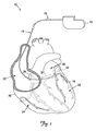
図1は、近位端16及び遠位端18を備えたリード14に結合されているパルス発生器12を有する心リズム管理システム10の略図である。図1に示されているように、リード14の遠位部分は、患者の心臓20内に配置され、患者の心臓は、右心房22、右心室24、左心房26及び左心室28を含む。図1に示されている実施形態では、リード14の遠位端18は、右心房22、冠状静脈洞口29を通り、そして冠状静脈洞31又は大心臓静脈33の枝中に経静脈的に案内される。リード14の図示の位置は、心臓20の左側をセンシングし若しくはこの左側にペーシング及び(又は)除細動エネルギーを送るために又は心臓20の左側に送られる治療手段を必要とする不整脈又は他の心臓障害を治療するために利用できる。加うるに、リード14は、心臓20の他の領域(例えば、右心室)内の治療を行うのにも使用できることは理解されよう。
FIG. 1 is a schematic diagram of a cardiac
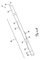
図2A及び図2Bは、本発明の一実施形態としての心臓用リード14の遠位部分50の略図である。図示のように、心臓用リード14は、近位端52、遠位端54及び近位端52と遠位端54との間に延びるリードルーメン57を備えたリード本体55を有している。本発明の一実施形態では、遠位部分50は、リード本体50の遠位側の約5〜10cm分である。加うるに、心臓用リード14の遠位部分50は、リードルーメン57を貫通して延びる導電性要素(図示せず)と電気的連絡状態にある1つ又は2つ以上の電極59を有している。
2A and 2B are schematic views of the
図2Aに示されているように、心臓用リード14の遠位部分50は、予備成形された自己拡張型固定部材60を有する。図2Aでは、自己拡張型固定部材60は、押しつぶし形態61で示されている。図2Bでは、固定部材60は、拡張形態62で示されている。本発明の一実施形態では、心臓用リード14は、従来型リード植え込み手技を利用する一方で、依然として自己拡張型固定部材60の作動を可能にするよう構成されている。具体的に説明すると、リード本体55は、自己拡張型固定部材60の配備及び(又は)引っ込みを妨害しないで、案内部材、例えばガイドワイヤ又はスタイレットがリードルーメンを通過することができるようにするよう構成されているのが良い。
As shown in FIG. 2A, the
自己拡張型固定部材60は、冠状血管(図3に示されている)内の標的部位での配備時に、押しつぶし形態61(図2Aに示されている)から予備成形拡張形態62(図2Bに示されている)に自動的に拡張することができる予備成形された渦巻き形、螺旋形又はコルク栓抜き形のワイヤ又はコイルである。本発明の一実施形態によれば、予備成形された自己拡張型固定部材60を形成するワイヤ又はコイルは、約0.005(0.127mm)〜約0.007インチ(0.1778mm)の有効外径を有している。自己拡張型固定部材60は、遠位端63、近位端64及び本体65を有している。自己拡張型固定部材60の遠位端63は、適当な手段、例えば接着剤を用いてリード本体55の遠位部分50に固定されている。自己拡張型固定部材60の遠位端63を固定する他の手段は、当業者には容易に明らかであろう。
The self-expanding
固定部材60の固定された遠位端63とは対照的に、近位端64は、リード本体55に摺動可能に隣接して位置している。具体的に説明すると、近位端64はリード本体55には取り付けられておらず、拡張中、遠位側の方向に、押しつぶし中、近位側の方向に摺動することができる。自己拡張型固定部材60は、リードの電極59に隣接して又はこの近くでリード本体55の遠位部分50に被せて位置決めされている。
In contrast to the fixed
本発明の別の実施形態によれば、近位端64は、保護特徴部、例えばポリマーカバー又はエンドキャップを有する。この実施形態では、保護特徴部は、血管壁を血管内への固定部材60の配備中、潜在的な損傷から保護する。保護特徴部は、螺旋体62を解除して、この周りに形成されている線維形成部を通って取り出すことができるよう取り外し可能である。別の例示の実施形態によれば、保護特徴部は、長期間にわたって溶ける生体吸収性ポリマー(例えば、マンニトール)である。
According to another embodiment of the invention, the
図3に示されているように、リード本体55を血管の管腔70中に挿入する。拡張形態62では、自己拡張型固定部材60は、リード本体55の一方の側に付勢される。これにより、リード本体55をこれが配備される冠状血管72の一方の壁71まで押すことができ、それにより血管壁71への電極の接触具合が向上する。固定部材60は、相当大きな力を血管壁71に及ぼすが、冠状血管72内でのリード本体55の遠位部分50の調整及び再位置決めを可能にする。本発明の一実施形態によれば、固定部材60は、拡張時に、固定部材60が遠位部分50を冠状血管72内に固定して安定化することができるよう十分な摩擦力を血管壁71に及ぼす形状、直径、弾性及び構造を有している。近位側への抜去力をリード本体55に加えると、張力が固定部材60の遠位端に加えられる。拡張状態の固定部材60の遠位端に張力を加えることにより、固定部材60は、先ず最初に、更に拡張し、それにより追加の摩擦力が血管壁71に加えられる。
As shown in FIG. 3, the
固定部材60は、血管管腔70の内径73によって定められたサイズまで拡張する。本発明の一実施形態では、自己拡張型固定部材60は、これが配備される血管の予想解剖学的直径よりも僅かに大きい有効直径まで拡張する。本発明の一実施形態によれば、自己拡張型固定部材60の有効直径は、約4〜約8ミリメートルである。自己拡張型固定部材60は、いったん血管管腔70内に位置決めされると、これが血管壁71に力を及ぼすので変形し又は平べったくなることができる。
The
予備成形された自己拡張型固定部材60を当該技術分野において知られている任意適当な断面形状の種々の超弾性又は自己拡張性材料で形成できる。本発明の一実施形態によれば、選択される材料は、形状記憶材料であり、冠状血管内の標的部位のところへの配備時に拡張するのに十分な弾性を備えている。かかる自己拡張性材料は、当該技術分野においては周知である。一実施形態では、自己拡張型固定部材60は、ニッケル‐チタン合金、例えばニチノールで作られる。本発明の他の実施形態では、自己拡張型固定部材60を他の材料で作ることができ、かかる材料としては、次のもの、即ち、生体適合性ポリマー、生体再吸収性ポリマー、ポリウレタン、チタン、スプリングテンパー316SS、MP35N、白金又は白金合金及びこれらの組み合わせが挙げられるが、これらには限定されない。一材料又は材料の組み合わせは、これが自己拡張型固定部材60を変形させないで拡張したり押しつぶしたりすることができる高い弾性範囲をもつように選択されるべきである。本発明の一実施形態では、ヤング率は、約12Msi〜約29Msiである。
The preformed self-expanding
本発明の一実施形態によれば、導電性材料が固定部材60について選択される。この実施形態では、心臓用リード14は、固定部材60が導電性要素と電気的連絡関係をなすよう構成される。この形態により、固定部材60を電極として用いることができる。固定部材60の付勢形態により、血管壁71との電気的接触が保証される。
According to one embodiment of the invention, a conductive material is selected for the securing
本発明の別の実施形態によれば、固定部材60は、標準型視覚化技術を利用して挿入及び(又は)抜去中、固定部材60を視覚化することができるよう放射線不透過性物質から成るのが良く、或いは変形例として、かかる放射線不透過性物質で被覆されても良い。変形例として、リード本体55の遠位部分50は、視覚化を助けるために放射線不透過性マーカを有しても良い。
According to another embodiment of the present invention, the
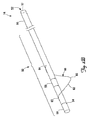
図2B及び図4Bは、予備成形された自己拡張型固定部材60,100を拡張形態で示している。拡張形態では、本発明の例示の一実施形態によれば、自己拡張型固定部材60,100の長さは、リード本体55の遠位部分50に沿って約0.5〜約1.5インチ(約12.7mm〜約38.1mm)である。自己拡張型固定部材60,100は、その拡張長さに沿って、1つ〜4つのピークを有するのが良い。図2Bに示されている本発明の例示の一実施形態では、予備成形自己拡張型固定部材60は、拡張形態にあるとき単一のピークを有する。図4Bに示されている別の例示の実施形態では、自己拡張型固定部材100は、2つ以上のピークを有する。追加のピークは、当業者により適宜決定できる。図4Bに示された実施形態では、ピークは、一定間隔で生じており、通常、典型的な螺旋固定部材に見受けられる間隔よりも互いに更に間隔を置いて位置している。本発明の別の実施形態によれば、自己拡張型固定部材60は、予備成形された細長い螺旋体である。
2B and 4B show the preformed self-expanding
図4A及び図4Bに示されている本発明の別の実施形態によれば、予備成形自己拡張型固定部材100は、2つのピークを含む螺旋形、渦巻き形又はコルク栓抜き形のワイヤである。図4Aは、固定部材100を押しつぶし形態101で示している。図4Bは、固定部材100を拡張形態102で示している。図2A及び図2Bに示されている固定部材と同様、固定部材100は、リード電極59に隣接して又はこの近くでリード本体55の遠位部分50に被せて位置決めされている。固定部材100は、リード本体55の遠位端54に固定された遠位端113を有している。自己拡張型固定部材100の遠位端113は、適当な手段、例えば接着剤を用いてリード本体55に固定されている。固定部材100の遠位端113を固定する他の手段は、当業者には容易に明らかであろう。自己拡張型固定部材100の固定された遠位端113とは対照的に、近位端123は、リード本体55に摺動可能に隣接して位置している。具体的に説明すると、近位端123は、リード本体55には取り付けられておらず、拡張中、遠位側の方向に、押しつぶし中、近位側の方向に摺動することができる。
According to another embodiment of the present invention shown in FIGS. 4A and 4B, the preformed self-expanding
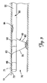
図5A及び図5Bは、血管管腔70内での運搬及び植え込みの際の図2A及び図2Bに示されている心臓用リード14の遠位部分50を示している。図5Aに示されているように、心臓用リード本体55の遠位部分50は、デリバリー(運搬又は送達用)シース155内に挿入され、このデリバリーシースは、自己拡張型固定部材60を押しつぶしてこれをその押しつぶし形態61にする。リード本体55の遠位部分50が冠状血管内の標的部位にいったん到達すると、リード本体55の遠位部分50は露出され、それにより自己拡張型部材60は、拡張して図5Bに示されたその拡張形態60を取ることができる。図5Bに示されているように、自己拡張型固定部材60は、その拡張形態62では、リード本体55の一方の側に付勢される。
FIGS. 5A and 5B show the
本発明の一実施形態では、デリバリーシース155は、リード14の遠位部分50上でこれに沿って近位側に引っ込められ、それによりリード本体55の遠位部分50を露出させる。本発明の別の実施形態では、リード本体55の遠位部分50をデリバリーシース155の遠位端部160越しに遠位側に押して遠位部分50は露出され、固定部材60がその押しつぶし状態61から解除され、それにより固定部材が自動的に拡張してその拡張状態62を取るようにする。加うるに、本発明の一実施形態によれば、デリバリーシース155を血管管腔70から完全に抜去する。変形例として、リード本体55の遠位部分50がいったん露出されると、デリバリーシース160は、血管管腔70内に位置したままである。
In one embodiment of the invention, the
デリバリーシース155は、自己拡張型固定部材を押しつぶし形態に保持するのに十分な強度を備えた種々の生体適合性材料で構成できる。例えば、シース155は、種々の適当な生体適合性ポリマー材料、例えば医用シリコーン又はポリウレタンで形成できる。
The
図6に示されている本発明の変形実施形態では、心臓用リード14は、自己拡張型固定部材60を含めてリード14の遠位部分50を被覆した生体吸収性材料175を有している。生体吸収性被膜175は、心臓血管内の標的部位への遠位部分50の送達中、自己拡張型固定部材60を押しつぶし状態61に保持することができる。この実施形態によれば、案内カテーテル又はデリバリーシースを用いてリード14の遠位部分50を運搬する。ガイドカテーテル又はデリバリーシースを抜去すると、生体吸収性被膜175を含む遠位部分50が露出される。生体吸収性被膜175は、血液の流れ中に容易に吸収され、それにより自己拡張型固定部材60は、自動的に拡張してその所定の拡張状態を取ることができる。遠位部分50を被覆するために用いられる生体吸収性材料の一例は、糖、例えばマンニトールである。当該技術分野において知られている他の糖及び生体吸収性材料を用いて遠位部分50を被覆しても良い。
In the alternative embodiment of the invention shown in FIG. 6, the
本発明の実施形態としての自己拡張型固定部材60により、心臓用リード本体55の遠位部分50を急性的又は慢性的固定が行われた後に再位置決めすると共に(或いは)抜去することができる。これは、1つには、固定部材60の形態がリード本体55に取り付けられていないその遠位端64を備えていることに起因している。加うるに、固定部材60を構成するワイヤは、組織の内方成長を可能にする構造的要素、例えばメッシュ材、細孔、ねじ山、歯を備えていない。線維形成は、固定部材60を構成するワイヤの周りに生じることがある。再位置決め又は抜去中、リードを先ず最初に遠位側の方向に動かして固定部材60の近位端64をこの周りに生じている線維形成部から自由にする。次に、リードの遠位部分50を標的場所の近位側の位置まで動かす。リードの遠位部分50が図7に方向を表す矢印で示されている近位側の方向に動き続けると、固定部材60は、脱出状態になり、その結果、固定部材60の近位端64が固定された遠位端63の遠位側に位置してこの遠位端63をひきずるようになる。次に、脱出状態の固定部材60は、固定部材60の最初の配備により線維形成部に形成された経路を辿る。次に、リード50を再位置決めするか抜去するかのいずれかを行うことができる。
The self-expanding
図8は、本発明の実施形態に従って心臓用リード14を植え込む方法を示している。
FIG. 8 illustrates a method for implanting a
最初に、1本又は2本以上のデリバリーシース又は案内カテーテルを所望の血管中に案内するのが良い(ブロック302)。固定部材が押しつぶし形態にあるように構成されている心臓用リードを次に、案内部材、例えばガイドワイヤ又はスタイレットを用いてデリバリーシース又は案内カテーテルを通って心臓血管内の標的部位まで案内するのが良い(ブロック304)。リードの遠位端を標的部位に位置決めした後、次に、固定部材をその拡張形態に展開してこれを患者の血管管腔の内面に接触させ、心臓用リードの遠位端を所望の部位に固定するのが良い(ブロック306)。固定後、リード器具の遠位端を外さないでデリバリーシース及び案内部材を抜去するのが良い(ブロック308)。固定部材は、リード器具がデリバリーシースの抜去の際又は通常の生理学的活動の結果として、外れた状態又は再位置決めされた状態になるのを阻止するよう実質的に永続的に配備可能である。固定部材を心臓用リードの急性的固定又は慢性的固定に用いることができる。固定部材を所望に応じて、急性的固定後又は慢性的固定後であっても再位置決めし又は抜去することができる。固定部材を自由にするため、リードを近位側の位置まで引っ張る(ブロック310)。固定部材をいったん自由にすると、リードを再位置決めするか抜去するかのいずれかを行うことができる(ブロック312,314)。
Initially, one or more delivery sheaths or guide catheters may be guided into the desired blood vessel (block 302). A cardiac lead configured such that the fixation member is in a collapsed configuration is then guided through a delivery sheath or guide catheter to a target site within the cardiovascular vessel using a guide member, such as a guide wire or stylet. Is good (block 304). After positioning the distal end of the lead at the target site, the fixation member is then deployed into its expanded configuration and brought into contact with the inner surface of the patient's vascular lumen, and the distal end of the cardiac lead is placed at the desired site. (Block 306). After fixation, the delivery sheath and guide member may be removed without removing the distal end of the lead device (block 308). The fixation member is substantially permanently deployable to prevent the lead device from becoming dislodged or repositioned upon withdrawal of the delivery sheath or as a result of normal physiological activity. The fixation member can be used for acute or chronic fixation of the cardiac lead. The fixation member can be repositioned or removed even after acute or chronic fixation, as desired. The lead is pulled to a proximal position to free the fixation member (block 310). Once the fixation member is free, the lead can either be repositioned or removed (
本発明の範囲から逸脱することなく、上述した例示の実施形態の種々の改造例及び追加例を想到することができる。例えば、上述の実施形態は、特定の特徴に係るが、本発明の範囲は、特徴の種々の組み合わせを備えた実施形態及び説明した特徴の全てを備えているわけではない実施形態をも含む。したがって、本発明の範囲は、特許請求の範囲に記載された本発明の範囲に属するかかる変更例、改造例及び変形例をこれらの全ての均等例と一緒に包含するものである。 Various modifications and additions of the above-described exemplary embodiments can be devised without departing from the scope of the present invention. For example, although the embodiments described above relate to particular features, the scope of the present invention includes embodiments with various combinations of features and embodiments that do not have all of the features described. Accordingly, the scope of the invention is intended to embrace all such equivalents, alterations, modifications and variations that fall within the scope of the invention as defined by the appended claims.
Claims (10)
近位端、遠位端、及び前記近位端と前記遠位端との間に延びるルーメンを備えたリード本体と、
ルーメン内に延びる導電性要素と、
前記リード本体に設けられ、前記導電性要素と電気的連絡状態にある少なくとも1つの電極と、
前記リード本体の遠位部分に被せて位置決めされた予備成形自己拡張型螺旋固定部材とを有し、前記固定部材は、前記リード本体に固定された遠位端及び前記リード本体に摺動可能に隣接した、取り付けられていない近位端を有し、取り付けられていない近位端は、前記固定部材の拡張中、遠位側の方向に、前記固定部材の押しつぶし中、近位側の方向に摺動することができるように構成され、前記固定部材は、拡張形態において、前記固定部材が前記リード本体の所与の側に付勢されるよう予備成形されている、心臓用リード。 A heart lead,
A lead body comprising a proximal end, a distal end, and a lumen extending between the proximal end and the distal end;
A conductive element extending into the lumen;
At least one electrode provided in the lead body and in electrical communication with the conductive element;
A preformed self-expanding helical fixation member positioned over a distal portion of the lead body, the fixation member being slidable on the distal end fixed to the lead body and the lead body An adjacent, unattached proximal end, the unattached proximal end in the distal direction during expansion of the fixation member, in the proximal direction during crushing of the fixation member A cardiac lead configured to be slidable, wherein the fixation member is pre-shaped in an expanded configuration such that the fixation member is biased to a given side of the lead body.
Applications Claiming Priority (3)
| Application Number | Priority Date | Filing Date | Title |
|---|---|---|---|
| US11/627,194 US7662132B2 (en) | 2007-01-25 | 2007-01-25 | Expandable member for venous lead fixation |
| US11/627,194 | 2007-01-25 | ||
| PCT/US2008/051695 WO2008091886A1 (en) | 2007-01-25 | 2008-01-22 | Expandable member for venous lead fixation |
Publications (3)
| Publication Number | Publication Date |
|---|---|
| JP2010516404A JP2010516404A (en) | 2010-05-20 |
| JP2010516404A5 JP2010516404A5 (en) | 2011-03-24 |
| JP5327875B2 true JP5327875B2 (en) | 2013-10-30 |
Family
ID=39370905
Family Applications (1)
| Application Number | Title | Priority Date | Filing Date |
|---|---|---|---|
| JP2009547378A Expired - Fee Related JP5327875B2 (en) | 2007-01-25 | 2008-01-22 | Expandable member for intravenous lead fixation |
Country Status (4)
| Country | Link |
|---|---|
| US (1) | US7662132B2 (en) |
| EP (1) | EP2121118A1 (en) |
| JP (1) | JP5327875B2 (en) |
| WO (1) | WO2008091886A1 (en) |
Families Citing this family (10)
| Publication number | Priority date | Publication date | Assignee | Title |
|---|---|---|---|---|
| US8126571B2 (en) * | 2008-06-23 | 2012-02-28 | Cardiac Pacemakers, Inc. | Expandable assembly for cardiac lead fixation |
| US20100137927A1 (en) * | 2008-12-01 | 2010-06-03 | Tengiz Tkebuchava | Multifunctional cardiac pacemaker system |
| US8753708B2 (en) * | 2009-09-02 | 2014-06-17 | Cardiac Pacemakers, Inc. | Solventless method for forming a coating on a medical electrical lead body |
| WO2011050396A1 (en) * | 2009-10-29 | 2011-05-05 | Aortech Biomaterials Pty Ltd | Polyurethane header formed directly on implantable electrical devices |
| CA2812532A1 (en) * | 2010-09-28 | 2012-04-12 | The Board Of Trustees Of The Leland Stanford Junior University | Device and method for positioning an electrode in tissue |
| JP2013034535A (en) * | 2011-08-04 | 2013-02-21 | Olympus Corp | Electrical stimulation electrode assembly |
| EP2559453B1 (en) * | 2011-08-18 | 2014-07-16 | Sorin CRM SAS | Lead implantable in the coronary vessels for multi-zone stimulation of a left heart chamber |
| JP6654915B2 (en) * | 2016-01-26 | 2020-02-26 | アドリアカイム株式会社 | Medical electrical stimulation electrode and medical electrical stimulation device |
| US20220241599A1 (en) * | 2019-05-09 | 2022-08-04 | Incube Labs, Llc | Anchor system for retaining a device in tissue |
| US20210138239A1 (en) | 2019-09-25 | 2021-05-13 | Swift Sync, Llc | Transvenous Intracardiac Pacing Catheter |
Family Cites Families (18)
| Publication number | Priority date | Publication date | Assignee | Title |
|---|---|---|---|---|
| US4317459A (en) * | 1979-06-28 | 1982-03-02 | Medtronic, Inc. | Fixation loop for transvenous leads |
| US5603694A (en) * | 1995-10-17 | 1997-02-18 | Brown; Joe E. | Infusion coil apparatus and method for delivering fluid-based agents intravascularly |
| US6161029A (en) * | 1999-03-08 | 2000-12-12 | Medtronic, Inc. | Apparatus and method for fixing electrodes in a blood vessel |
| US6136021A (en) * | 1999-03-23 | 2000-10-24 | Cardiac Pacemakers, Inc. | Expandable electrode for coronary venous leads |
| US6556873B1 (en) * | 1999-11-29 | 2003-04-29 | Medtronic, Inc. | Medical electrical lead having variable bending stiffness |
| US6584362B1 (en) * | 2000-08-30 | 2003-06-24 | Cardiac Pacemakers, Inc. | Leads for pacing and/or sensing the heart from within the coronary veins |
| US6909920B2 (en) * | 2001-04-27 | 2005-06-21 | Medtronic, Inc. | System and method for positioning an implantable medical device within a body |
| US6711443B2 (en) * | 2001-07-25 | 2004-03-23 | Oscor Inc. | Implantable coronary sinus lead and method of implant |
| US7027852B2 (en) * | 2002-05-21 | 2006-04-11 | Pacesetter, Inc. | Lead with distal tip surface electrodes connected in parallel |
| US6968237B2 (en) * | 2002-05-22 | 2005-11-22 | Pacesetter, Inc. | Implantable coronary sinus lead and lead system |
| US7107105B2 (en) | 2002-09-24 | 2006-09-12 | Medtronic, Inc. | Deployable medical lead fixation system and method |
| US20040243210A1 (en) * | 2003-05-30 | 2004-12-02 | Morgan Kevin L. | Fixation of a left heart medical lead in the coronary sinus |
| US20050070981A1 (en) * | 2003-09-29 | 2005-03-31 | Sumit Verma | Active fixation coronary sinus lead apparatus |
| US20050080472A1 (en) * | 2003-10-10 | 2005-04-14 | Atkinson Robert Emmett | Lead stabilization devices and methods |
| EP1618919B1 (en) * | 2004-07-20 | 2012-07-04 | Biotronik CRM Patent AG | Fixation means for implantable electrodes and catheters |
| US8489189B2 (en) * | 2004-10-29 | 2013-07-16 | Medtronic, Inc. | Expandable fixation mechanism |
| US20060276869A1 (en) | 2005-06-03 | 2006-12-07 | Seth Worley | Coronary sinus lead for pacing the left atrium |
| US20080147181A1 (en) * | 2006-12-19 | 2008-06-19 | Sorin Biomedica Cardio S.R.L. | Device for in situ axial and radial positioning of cardiac valve prostheses |
-
2007
- 2007-01-25 US US11/627,194 patent/US7662132B2/en not_active Expired - Fee Related
-
2008
- 2008-01-22 EP EP08728070A patent/EP2121118A1/en not_active Withdrawn
- 2008-01-22 JP JP2009547378A patent/JP5327875B2/en not_active Expired - Fee Related
- 2008-01-22 WO PCT/US2008/051695 patent/WO2008091886A1/en active Application Filing
Also Published As
| Publication number | Publication date |
|---|---|
| EP2121118A1 (en) | 2009-11-25 |
| US7662132B2 (en) | 2010-02-16 |
| JP2010516404A (en) | 2010-05-20 |
| US20080183267A1 (en) | 2008-07-31 |
| WO2008091886A1 (en) | 2008-07-31 |
Similar Documents
| Publication | Publication Date | Title |
|---|---|---|
| JP5327875B2 (en) | Expandable member for intravenous lead fixation | |
| US7330765B2 (en) | Cardiac lead having self-expanding fixation features | |
| EP1877131B1 (en) | Fixation device for coronary venous lead | |
| EP2051771B1 (en) | Medical electrical lead with deployable fixation features | |
| US8052731B2 (en) | Medical electrical lead with expandable fixation features | |
| JP5108876B2 (en) | Cardiac lead assembly having a pluggable stiffening structure for fixation | |
| US20050080472A1 (en) | Lead stabilization devices and methods | |
| JP2009504331A (en) | Fixing and removing leads | |
| JP5048764B2 (en) | Cardiac lead with stiffening structure for fixation | |
| US20070293923A1 (en) | Lead with orientation feature | |
| WO2003020365A1 (en) | Method and apparatus for fixation of an implantable stimulation lead | |
| US20180154123A1 (en) | Implants and systems for electrically isolating one or more pulminary veins | |
| WO2010041216A1 (en) | Apparatus and method for anchoring an elongated object in body lumens | |
| US8175724B2 (en) | Vascular fixation device |
Legal Events
| Date | Code | Title | Description |
|---|---|---|---|
| A521 | Request for written amendment filed |
Free format text: JAPANESE INTERMEDIATE CODE: A523 Effective date: 20110120 |
|
| A621 | Written request for application examination |
Free format text: JAPANESE INTERMEDIATE CODE: A621 Effective date: 20110120 |
|
| A131 | Notification of reasons for refusal |
Free format text: JAPANESE INTERMEDIATE CODE: A131 Effective date: 20121022 |
|
| A977 | Report on retrieval |
Free format text: JAPANESE INTERMEDIATE CODE: A971007 Effective date: 20121025 |
|
| A601 | Written request for extension of time |
Free format text: JAPANESE INTERMEDIATE CODE: A601 Effective date: 20130122 |
|
| A602 | Written permission of extension of time |
Free format text: JAPANESE INTERMEDIATE CODE: A602 Effective date: 20130129 |
|
| A521 | Request for written amendment filed |
Free format text: JAPANESE INTERMEDIATE CODE: A523 Effective date: 20130419 |
|
| TRDD | Decision of grant or rejection written | ||
| A01 | Written decision to grant a patent or to grant a registration (utility model) |
Free format text: JAPANESE INTERMEDIATE CODE: A01 Effective date: 20130701 |
|
| A61 | First payment of annual fees (during grant procedure) |
Free format text: JAPANESE INTERMEDIATE CODE: A61 Effective date: 20130718 |
|
| R150 | Certificate of patent or registration of utility model |
Free format text: JAPANESE INTERMEDIATE CODE: R150 |
|
| RD03 | Notification of appointment of power of attorney |
Free format text: JAPANESE INTERMEDIATE CODE: R3D03 |
|
| R250 | Receipt of annual fees |
Free format text: JAPANESE INTERMEDIATE CODE: R250 |
|
| LAPS | Cancellation because of no payment of annual fees |