JP2009538805A - Structure of the drive device for the traveler, a method for replacing the drive belt of the handrail belt of the handrail of the traveler, and a support member for the handrail belt of the handrail of the traveler - Google Patents
Structure of the drive device for the traveler, a method for replacing the drive belt of the handrail belt of the handrail of the traveler, and a support member for the handrail belt of the handrail of the traveler Download PDFInfo
- Publication number
- JP2009538805A JP2009538805A JP2009512629A JP2009512629A JP2009538805A JP 2009538805 A JP2009538805 A JP 2009538805A JP 2009512629 A JP2009512629 A JP 2009512629A JP 2009512629 A JP2009512629 A JP 2009512629A JP 2009538805 A JP2009538805 A JP 2009538805A
- Authority
- JP
- Japan
- Prior art keywords
- belt
- handrail
- drive
- drive belt
- support member
- Prior art date
- Legal status (The legal status is an assumption and is not a legal conclusion. Google has not performed a legal analysis and makes no representation as to the accuracy of the status listed.)
- Pending
Links
- 238000000034 method Methods 0.000 title claims abstract description 24
- 238000009434 installation Methods 0.000 claims abstract description 26
- 230000005540 biological transmission Effects 0.000 description 12
- 230000008901 benefit Effects 0.000 description 7
- 238000005452 bending Methods 0.000 description 4
- 238000012423 maintenance Methods 0.000 description 4
- 230000006870 function Effects 0.000 description 3
- 230000001681 protective effect Effects 0.000 description 2
- 238000004904 shortening Methods 0.000 description 2
- 238000010276 construction Methods 0.000 description 1
- 230000007659 motor function Effects 0.000 description 1
Images


Classifications
-
- B—PERFORMING OPERATIONS; TRANSPORTING
- B66—HOISTING; LIFTING; HAULING
- B66B—ELEVATORS; ESCALATORS OR MOVING WALKWAYS
- B66B23/00—Component parts of escalators or moving walkways
- B66B23/02—Driving gear
- B66B23/04—Driving gear for handrails
-
- B—PERFORMING OPERATIONS; TRANSPORTING
- B66—HOISTING; LIFTING; HAULING
- B66B—ELEVATORS; ESCALATORS OR MOVING WALKWAYS
- B66B23/00—Component parts of escalators or moving walkways
- B66B23/22—Balustrades
-
- Y—GENERAL TAGGING OF NEW TECHNOLOGICAL DEVELOPMENTS; GENERAL TAGGING OF CROSS-SECTIONAL TECHNOLOGIES SPANNING OVER SEVERAL SECTIONS OF THE IPC; TECHNICAL SUBJECTS COVERED BY FORMER USPC CROSS-REFERENCE ART COLLECTIONS [XRACs] AND DIGESTS
- Y10—TECHNICAL SUBJECTS COVERED BY FORMER USPC
- Y10T—TECHNICAL SUBJECTS COVERED BY FORMER US CLASSIFICATION
- Y10T29/00—Metal working
- Y10T29/49—Method of mechanical manufacture
- Y10T29/49826—Assembling or joining
Abstract
本発明は、トラベレータ、動く歩道、エスカレータ等の駆動装置における構造と、動く歩道等に備えられた手すりの手すりベルトを交換する方法とに関する。本発明の動く歩道等は、駆動装置(1)に加えて、手すりベルト(12)を備えた少なくとも1つの手すり(13)を有し、また駆動装置(1)は、少なくとも1つの駆動モータ(2)と、手すり(12)の支持部材(10)と、駆動モータ(2)の回転運動を支持部材(10)へつなぐ駆動ベルト(8)とを有する。支持部材は駆動ベルト(8)の使用に適した実質的に大径の支持用ホイール(10)である。本発明による方法によって、駆動ベルト(8)は、駆動ベルト(8)を支持用ホイール(10)上の設置溝(14)へ固定することによって定位置に配置されて、また支持用ホイール(10)を回転させることによって、駆動ベルト(8)を支持用ホイール(10)の周囲の定位置に配設される。本発明による動く歩道、移動する歩道、エスカレータ等の手すり(13)の手すりベルト(12)の支持部材は支持用ホイールであり、この支持用ホイールは、駆動ベルト(8)を定位置に配置するのに際し、支持用ホイールにある駆動ベルト(8)を支持用ホイールの縁上へつないで配置する連結要素(14)を有する。
【選択図】図2
The present invention relates to a structure in a driving device such as a traveler, a moving sidewalk, and an escalator, and a method for exchanging a handrail belt of a handrail provided on the moving sidewalk. The moving sidewalk or the like of the present invention has at least one handrail (13) provided with a handrail belt (12) in addition to the drive device (1), and the drive device (1) includes at least one drive motor ( 2), a support member (10) for the handrail (12), and a drive belt (8) for connecting the rotational motion of the drive motor (2) to the support member (10). The support member is a substantially large diameter support wheel (10) suitable for use with the drive belt (8). By means of the method according to the invention, the drive belt (8) is placed in place by fixing the drive belt (8) to the installation groove (14) on the support wheel (10) and the support wheel (10 ) Is rotated to place the drive belt (8) in a fixed position around the support wheel (10). The supporting member of the handrail belt (12) of the handrail (13) of the moving sidewalk, the moving sidewalk, the escalator or the like according to the present invention is a supporting wheel, and this supporting wheel arranges the driving belt (8) at a fixed position. In this case, it has a connecting element (14) for placing the drive belt (8) on the support wheel on the edge of the support wheel.
[Selection] Figure 2
Description
本発明は、請求項1の前段に記載のトラベレータ等の駆動装置の構造と、請求項7の前段に記載のトラベレータ等に組み込まれた手すりの手すりベルトの駆動ベルトを交換する方法と、請求項10の前段に記載のトラベレータ等の手すりの手すりベルトの支持部材とに関する。
The present invention relates to a structure of a drive device such as a traveler according to the first stage of
トラベレータ、動く傾斜歩道、動く歩道は一般的に少なくとも1つの手すりを有し、その周囲に手すりベルトがループとして取り付けられている。この手すりは、乗客が自身を支えるのに用いることができ、また通常は、階段、傾斜歩道、もしくは歩道の実用パネルとほとんど同じ速度で移動する。従来技術の構造において、手すりの手すりベルトは、例えばパネルと同じ駆動装置で駆動される。駆動装置は一般的にシステムのいずれかの端部に配置される。手すりの手すりベルトは、レールの上を移動する少なくとも1つの支持部を有し、この上に乗客は自分の手を置くことができ、またレールの下縁端部と同じ面の実質的に見えないところで回転する戻り部、および支持部と戻り部との間のレールの両端部に、湾曲した屈曲部を有している。ベルトの屈曲部が端部に配設された屈曲ガイドを周回するとき、レールの端部で手すりベルトの進行方向が変わるが、従来技術では、これを、例えば複数の支持ロールを互いに適切な間隔で湾曲形状に配設することで行っていた。上述の支持ロールで構成される方式の1つが米国特許第 5,634,546号に開示されている。 A traveler, a moving inclined sidewalk, and a moving sidewalk generally have at least one handrail, around which a handrail belt is attached as a loop. This handrail can be used by passengers to support themselves, and usually travels at about the same speed as a staircase, a sloping sidewalk, or a practical sidewalk panel. In the prior art structure, the handrail belt of the handrail is driven by, for example, the same driving device as the panel. The drive is typically located at either end of the system. The handrail belt of the handrail has at least one support that moves over the rail on which the passenger can place his hand and is substantially visible on the same plane as the lower edge of the rail. A return portion that rotates where there is not, and curved bent portions at both ends of the rail between the support portion and the return portion. When the bent part of the belt circulates the bending guide provided at the end part, the traveling direction of the handrail belt changes at the end part of the rail. In the prior art, for example, a plurality of support rolls are appropriately spaced from each other. This is done by arranging in a curved shape. One system comprising the above-described support roll is disclosed in US Pat. No. 5,634,546.
米国特許第 5,117,960号には、例えば上述のようなトラベレータの形式における、トラベレータの手すりの手すりベルトの牽引機械装置が説明されている。この公報では、手すりベルトの戻り部に牽引装置が配され、この牽引装置は、手すりベルトの方へ互いに押し合う2つのベルトを有し、これら両者で閉ループを形成している。両ベルトは、ベルトによる閉ループの内側にある複数のバネ負荷式ロールによって手すりベルトに対して押し付けられる。手すりベルトの牽引ベルトは手すりベルトをこの手すりベルトの内面に対して押し付け、支持体として働くベルトは手すりベルトをその手すりベルトの外面に対して、すなわち乗客に見える面に対して押し付ける。この方式における問題は、多数のロールがあるため、構造に費用がかかり、かつ複雑になること、および多大な保守を必要とすることである。別の問題は、手すりベルトの外面を押圧する支持ベルトが、乗客に見える手すりベルトの外面を摩耗させ、それによって手すりベルトの稼動寿命を短くすることである。 U.S. Pat. No. 5,117,960 describes a traction machine for a handrail belt for a handrail of a traveler, for example in the form of a traveler as described above. In this publication, a traction device is arranged at the return portion of the handrail belt, and this traction device has two belts that press against each other toward the handrail belt, and both form a closed loop. Both belts are pressed against the handrail belt by a plurality of spring-loaded rolls inside the closed loop by the belt. The traction belt of the handrail belt presses the handrail belt against the inner surface of the handrail belt, and the belt acting as a support presses the handrail belt against the outer surface of the handrail belt, ie against the surface visible to the passenger. The problem with this scheme is that because of the large number of rolls, the construction is expensive and complex and requires a great deal of maintenance. Another problem is that the support belt that presses the outer surface of the handrail belt wears the outer surface of the handrail belt visible to the passenger, thereby shortening the service life of the handrail belt.
米国特許第 6,450,317号にはトラベレータの手すりの手すりベルトの他の牽引装置が開示され、ここではパレットと手すりの手すりベルトの両方を同一の機械装置で動かしている。手すりベルトの外面、すなわち乗客に見える面は駆動モータによって回転される駆動ベルトと摩擦接触する。複数の圧搾ロールが手すりベルトを駆動ベルトに向けて内側へ押し、接触をより確実にしている。この方式における問題も、多数の圧搾ロールとガイドロールがあるため、構造に費用がかかり、かつ複雑になること、および多大な保守を必要とすることである。加えて、別の問題は手すりベルトの外面を押圧する駆動ベルトが乗客に見える手すりベルトの外面を摩耗させ、これによって手すりベルトの稼動寿命を短くすることにある。このような理由から、手すりの材料は摩耗に対する強い耐性を持つものにする必要があるが、このことは費用がかかる。 U.S. Pat. No. 6,450,317 discloses another traction device for a handrail belt for a traveler's handrail, where both the pallet and the handrail belt of the handrail are moved by the same mechanical device. The outer surface of the handrail belt, ie the surface visible to the passenger, is in frictional contact with the drive belt rotated by the drive motor. A plurality of squeezing rolls push the handrail belt inward toward the drive belt to make contact more reliable. The problem with this system is that it has a large number of squeezing rolls and guide rolls, which makes the structure expensive and complex and requires a lot of maintenance. In addition, another problem is that the drive belt pressing the outer surface of the handrail belt wears the outer surface of the handrail belt visible to the passenger, thereby shortening the service life of the handrail belt. For this reason, handrail materials need to be highly resistant to wear, which is expensive.
また国際特許出願第 WO2005/075332号には手すりベルトを動かす方式が開示されている。ここでは、駆動機械を回転させるベルトは、支持ロールの周囲に輪として取り付けられている。ベルトは、手すりベルトの内面と接触するように取り付けられているため、手すりベルトは支持ロールを周回するのと同時に動く。 International Patent Application No. WO2005 / 075332 discloses a method for moving a handrail belt. Here, the belt for rotating the drive machine is attached as a ring around the support roll. Since the belt is mounted in contact with the inner surface of the handrail belt, the handrail belt moves simultaneously with the support roll.
本発明は、上述の欠点を解消し、手すりの手すりベルトの駆動ベルトが以前の方式ほど早く摩耗しないようにした、簡易で安価な、トラベレータ等の駆動機械における構造を実現することを目的とする。また、トラベレータ等に組み込まれた手すりの手すりベルトの駆動ベルトを、簡易で安価に交換する方法を実現することを目的とする。さらに、簡易で、省スペースで、保守が容易であって、設置または交換が容易な、トラベレータ等の手すりの手すりベルトの支持部材を実現することを目的とする。本発明の構造は請求項1の特徴段に開示したことを特徴とする。同様に、本発明による方法は請求項7の特徴段に開示したことを特徴とする。本発明による支持部材は請求項10の特徴段に開示したことを特徴とする。本発明の他の実施例はその他の請求項に開示したことを特徴とする。
An object of the present invention is to realize a simple and inexpensive structure in a drive machine such as a traveler that eliminates the above-mentioned drawbacks and prevents the handrail belt of a handrail from being worn as quickly as the previous method. . Another object of the present invention is to realize a simple and inexpensive method for exchanging a driving belt of a handrail belt of a handrail incorporated in a traveler or the like. It is another object of the present invention to provide a support member for a handrail belt of a handrail such as a traveler that is simple, space-saving, easy to maintain, and easy to install or replace. The structure of the present invention is disclosed in the characterizing stage of
本発明の実施例は、本願の明細書部分にも開示されている。本願に開示されている発明の内容は、特許請求の範囲に規定されているものとは別の形で規定することも可能である。また、本発明の内容は、特に表現あるいは内在するサブタスクの点から見た場合、または達成される利点あるいは一連の利点から見た場合、いくつかの別々の発明から成っていてもよい。その場合、特許請求の範囲に含まれる属性のいくつかは、別々の発明の概念からみて不必要であるかもしれない。同様に、本発明の各実施例に関連して説明したさまざまな細部を他の実施例で適用することができる。 Embodiments of the present invention are also disclosed in the specification part of the present application. The content of the invention disclosed in the present application may be defined in a form different from that defined in the claims. Also, the subject matter of the present invention may consist of several separate inventions, particularly in terms of expression or underlying subtasks, or in terms of the benefits or series of advantages achieved. In that case, some of the attributes included in the claims may be unnecessary from a separate inventive concept. Similarly, the various details described in connection with each embodiment of the invention may be applied in other embodiments.
本発明による構造の1つの利点は、手すりの手すりベルトの駆動ベルトと、機械装置に組み込まれたその他の部品とが迅速には摩耗せず、そのためこれらを交換する必要がなく、さらに機械装置が頻繁な保守を必要としないことにある。他の利点は、機械装置が簡易で、実施費用が安く、また部品が小さいため機械装置の組み立てが容易であることにある。また機械装置は、なかでも駆動ベルトの交換のため、手すりの幅方向に有利に薄く構成することができる。また本発明による構造は例えば本発明の方法を用いることで保守が容易である。本発明による方法の利点の1つは、手すりベルトもしくは手すりの駆動ベルトを迅速に、容易に、安い費用で設置または交換できることである。なぜなら、ベルト交換のためにフレーム構造を個々に分解する必要がないからである。本発明の支持部材の利点の1つは、ベルトを交換するためにフレーム構造を個々に分解する必要がないので、手すりの手すりベルトの駆動ベルトを迅速に、簡易に、かつ安い費用で設置または交換できることである。加えて、本発明による支持部材は、駆動ベルトが支持部材の縁を走行するので、手すりベルトの機械装置を簡易にでき、また薄い手すり構造にすることができる。 One advantage of the structure according to the invention is that the handrail handrail belt drive belt and other parts incorporated in the machine do not wear quickly, so that they do not need to be replaced, and the machine It does not require frequent maintenance. Another advantage is that the mechanical device is simple, the implementation cost is low, and the assembly is easy due to the small parts. In addition, the mechanical device can be advantageously made thin in the width direction of the handrail, especially for exchanging the drive belt. The structure according to the present invention can be easily maintained by using the method of the present invention, for example. One advantage of the method according to the invention is that a handrail belt or a handrail drive belt can be installed or replaced quickly, easily and at low cost. This is because there is no need to individually disassemble the frame structure for belt replacement. One advantage of the support member of the present invention is that it is not necessary to disassemble the frame structure individually in order to replace the belt, so that the handrail belt drive belt can be installed quickly or simply at a low cost. It can be exchanged. In addition, since the driving belt runs on the edge of the supporting member, the supporting member according to the present invention can simplify the mechanical device of the handrail belt and can have a thin handrail structure.
以下に、本発明をいくつかの実施例ならびに添付の図面を参照して詳細に説明する。 In the following, the present invention will be described in detail with reference to several examples and the accompanying drawings.
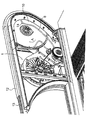
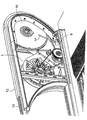
図1にトラベレータの一方の端部の側面図を示し、図2にその斜視側面図を示す。ここではトラベレータの駆動装置1およびその中に組み込まれている手すりの手すりベルトが配置され、駆動装置は少なくとも1つの電動機を有している。電動機には中心シャフト3が設けられ、また電動機は駆動モータ2として機能する。閉鎖されたベルト4はシャフト3にあるベルトホイールへ取り付けられ、ベルトはここから導かれて締め付けホイール5と伝動ホイール6とを周回する。ベルト4は閉ループを構成し、シャフト3にあるベルトホイール、ならびに締め付けホイール5および伝動ホイール6を周回して所望の張りを保って締め付けられている。駆動モータ2のシャフト3が回転すると、伝動ホイール6もベルト4を介して回転する。伝動ホイール6はトラベレータのパネルを、図示しないが用途に適した動力伝達方式によって動かすように配設されている。また、伝動ホイール6は駆動力を手すり13の手すりベルト12へ伝達するように配設され、この場合、駆動モータ2が同時に手すりの手すりベルト12を動かす。本発明による方式では、手すりの手すりベルト12の駆動装置1は実質的に手すり13の端部にあり、そこでは手すりベルト12がこの端部に配設されている屈曲ガイドを通過すると、手すりベルト12の走行方向が変わる。
FIG. 1 shows a side view of one end of the traveler, and FIG. 2 shows a perspective side view thereof. Here, a
また駆動ベルト8は、伝動ホイール6の回転シャフト7を周回するように配設され、シャフト7にあるベルトホイールから導かれて支持用ホイール10を周回する。この支持用ホイール10は、シャフト11で回転するよう取り付けられ、また手すりベルト12の支持部材として機能する。駆動ベルト8は、転向ホイール9の下を通過するように、シャフト7のベルトホイールと支持用ホイール10とを周回する閉ループを形成し、転向ホイールは、駆動ベルト8を締め付け、また駆動ベルト8の走行方向を変える。転向ホイール9の位置を調節することによって、駆動ベルト8を所望の張りで締めることができる。
The
手すりベルトの支持用ホイール10は、例えば大径の板状ホイールである。この直径は、支持用ホイールが手すりベルト12の屈曲部に適する屈曲ガイドを同時に形成するように寸法決めされている。構造上の方式にもよるが、支持用ホイール10の半径は、少なくとも支持用ホイール10と手すりベルト12との間の接触距離間において手すりベルト12のループの接触面となる内面の湾曲部の半径と実質的に同じ大きさであるか、または支持用ホイール10における手すりベルト12の湾曲部の半径よりもせいぜい駆動ベルト8の厚さ分だけ小さくした大きさである。
The
以下に詳細に説明する後段の方式において、手すりベルト12の屈曲部は支持用ホイール10を周回するように配設されるため、例えば手すりベルト12の接触面である内面と、支持用ホイール10の縁上の駆動ベルト8の外面15とが互いに摩擦接触する。駆動モータ2が伝動ホイール6を回転させると、支持用ホイール10も駆動ベルト8を介して回転する。駆動ベルト8と手すりベルト12とが互いに摩擦接触しているので、駆動ベルト8と手すりベルト12とが擦れ合った結果、支持用ホイール10が駆動ベルト8の牽引によって回転すると、手すりベルト12も動く。機械装置1のベルト変速装置は、トラベレータのパネルとその手すりベルト12が互いに所望の速度で動くよう取り付けられている。
In the latter method, which will be described in detail below, the bent portion of the
ベルト4および8は、歯付ベルトであることが望ましく、これらのベルトに連結されたベルトホイールと支持用ホイールとは、これらのベルトに合った歯切りが施されていることが望ましい。
The
図3は、伝動ホイール6のシャフト7に配され、また支持用ホイール10の周囲にある駆動ベルト8の交換が開始されている状態を示す。手すり端部の保護被覆部または保護光沢部と、古い駆動ベルトとは既に取り除かれ、新しい駆動ベルト8が支持用ホイール10の周囲に掛設されようとしている。支持用ホイール10の一方の側には、連結要素として機能する設置溝14が、その縁から内方へ、望ましくは支持用ホイールの中心軸に向かって、実質的には半径方向に延在し、設置される新規ベルト8の一部がその上へ取り付けられる。設置溝14は支持用ホイール10の軸方向に十分に深くて、交換中はこの溝に駆動ベルト8を保持する。しかし、設置溝は軸方向に、支持用ホイール全体にわたって延在する必要はない。また、設置溝を適切に円形の縁にすることができ、詰物をその中に入れることができる。この詰物は駆動ベルトが定位置に配されている間にしか取り出されない。
FIG. 3 shows a state in which the exchange of the
図4は、新しい駆動ベルト8の設置が図3における状態よりもさらに進んでいる状態を示す。この場合、支持用ホイール10は矢印Aの方向にある程度回転していて、駆動ベルト8は手すり12と支持用ホイール10との間の溝14に沿って動いている。同時にベルト8は設置溝14の後方の支持用ホイール10上にわたって位置するようになる。
FIG. 4 shows a state in which the installation of the
図5は、新しい駆動ベルト8の設置が完了した状態を示す。支持用ホイール10はすでにさらに回転し、設置溝14が動いてベルト8が設置溝から抜け出す。ここでは、新しい駆動ベルト8は、支持用ホイール10を周回し、転向ホイール9の下側で、伝動ホイール6のシャフト7にあるベルトホイールの周囲を通っている。
FIG. 5 shows a state in which the installation of the
本発明による方法によって、手すりの駆動ベルト8は、例えば次のように交換される。まず、機械装置を保護している部品があれば、これらをその側部から取り外し、そこで交換が行われるように機械装置の作業ができる状態にする。これらの部品は、例えば機械装置の側部のフレームプレートである。その後、例えば古いベルト8を切断しおよびその位置から引き抜いて取り外す。次に、支持用ホイール10を、新しい駆動ベルト8の連結要素として機能する設置溝14の設置開始に適した位置へ回転させ、新規の駆動ベルト8を設置溝14へ取り付ける。この後、支持用ホイール10を手または適切な工具によって回転させて、新しい駆動ベルト8を支持用ホイール10上に配置し、最終的に、ベルト8を設置溝14から抜けさせる。この後、新規駆動ベルト8をさらに伝動ホイール6のシャフト7にあるベルトホイールの周りに、また転向ホイール9の下側に掛設し、転向ホイール9の位置を調整することによってベルト8を所望の張りになるように締め付ける。
By the method according to the invention, the
本実施例においては、新規駆動ベルトによる古い駆動ベルトの交換のみを説明したが、当然、ベルトの交換以外の環境においても同様の構造および方法によって駆動ベルト8を定位置に配することが可能である。したがって、例えば装置の稼動に関しては、最初の設置の際に、定位置へ配すべき駆動ベルト8を同じように設置することができ、また、例えば保守もしくは他の作業に関しては、取り外したベルトを同じように定位置に入れ直すことができる。したがって、このような場合は新しい駆動ベルトを設置する必要はないが、その代わりに、前の駆動ベルトを使用可能である。一般的に、このことは駆動ベルト8の定位置への配置と称されている。
In the present embodiment, only the replacement of the old drive belt with the new drive belt has been described, but naturally the
本発明による手すりの手すりベルトの支持部材は、図1〜5では参照番号10で示す。支持部材は支持用ホイール10であり、この縁に支持用ホイールの駆動ベルト8が取り付けられて走行する。支持用ホイール10は連結要素14を有し、これは駆動ベルト8を定位置へ配設するのに際して、支持用ホイール10と手すりベルトとの間で、支持用ホイール10にある駆動ベルト8をつないで支持用ホイール10の縁へ配設する。同図において、連結要素14は実質的に支持用ホイール10の縁から内側へ延在する設置溝であり、駆動ベルト8の定位置への配置に関連して、この設置溝へ駆動ベルト8が取り付けられる。上述した溝状の連結要素は簡易なものであり、実質的に場所をとらない。希望するのであれば、設置溝を一時的に詰物で覆うことが可能である。支持用ホイール10の縁に設置された駆動ベルト8の経路は、支持用ホイール10と手すりベルト12との間を通るように配設されて、その外面15が手すりベルト12の内面と擦れ合うように接触し、かつ内面が支持用ホイール10に対して接触することが望ましい。このことが支持用ホイール10と駆動ベルト8との間の接触面積、および駆動ベルト8と手すり12との間の接触面積を大きくする。本発明による支持用ホイール10を用いて駆動ベルト8の設置を本願のいたるところで説明した方法で行うことができる。重要なことは、設置すべき駆動ベルト8を設置溝14へはめ込んだ後、支持用ホイール10を回転させて、新規の駆動ベルト8を支持用ホイール10に配し、最終的に、ベルト8を設置溝14から抜けさせることである。この支持部材10の構造も本願のいたるところで説明している。
A support member for a handrail belt of a handrail according to the present invention is indicated by
本発明による手すりベルトの支持部材は、駆動ベルト8が滑らかである実施例または駆動ベルトに歯切りがされている実施例などで利用可能である。したがって、駆動ベルト8は、その内面および/または外面を滑らかにすることもでき、または歯付きにすることもできる。駆動ベルト8の内面に歯切りを行った場合、支持用ホイールの外面にも適合する歯切りを行う。一実施例によれば、支持用ホイールの外縁に突起縁端部を構成して、これで少なくとも駆動ベルト8の一方の側であって支持用ホイールの縁の高さで、駆動ベルト8を縁に密着させて、駆動ベルト8を定位置に保持することを容易にすることができる。縁端部は駆動ベルトの厚さよりも狭くすることができ、この場合、上述したベルトにおける大きな接触面積は失われない。本発明の一実施例によれば、縁端部は駆動ベルト8以外の場所に、支持用ホイール10の縁の表面から延在する。この場合、摩擦によって派生した牽引力を支持用ホイールと手すりベルト12と間で生成させることができる。この場合の利点は、駆動ベルトの摩耗が小さいことである。
The support member for the handrail belt according to the present invention can be used in an embodiment in which the
本発明は上述の実施例にのみ限定されることはなく、特許請求の範囲内で改変することができることは当業者には明らかである。したがって、例えば、新規の駆動ベルトを配設するために、これを上述の設置溝へはめ込むことによる以外の方法で支持用ホイールへ固定することができる。設置時に、ベルトを例えば適切な形式の固定要素を用いて支持用ホイールへ固定することができる。 It will be apparent to those skilled in the art that the present invention is not limited to the embodiments described above, but can be modified within the scope of the claims. Thus, for example, in order to arrange a new drive belt, it can be fixed to the support wheel by a method other than by fitting it into the installation groove described above. Upon installation, the belt can be secured to the support wheel, for example using a suitable type of securing element.
さらに、新規の駆動ベルトを設置するためのさまざまな段階を上述した以外の順序で行うことができることは当業者にとって明らかである。例えば、開始時に新規の駆動ベルトを駆動ホイールのシャフトの周囲、および転向ホイールの下側に通すことができ、その後に、ベルトを支持用ホイールの周囲に通すことも可能である。 Furthermore, it will be apparent to those skilled in the art that the various steps for installing a new drive belt can be performed in an order other than those described above. For example, at the start, a new drive belt can be passed around the shaft of the drive wheel and below the turning wheel, after which the belt can be passed around the support wheel.
また、支持用ホイールの外輪だけを手すりベルトの接触面である内面に摩擦接触させることができるが、この場合、駆動ベルトが支持用ホイールの縁でさらに深くなることは当業者には明らかである。このような場合、手すりはこれが支持用ホイールの外縁により直接牽引されることによって動かされる。 Further, only the outer ring of the support wheel can be brought into frictional contact with the inner surface, which is the contact surface of the handrail belt. In this case, it is obvious to those skilled in the art that the drive belt becomes deeper at the edge of the support wheel. . In such a case, the handrail is moved by being pulled directly by the outer edge of the support wheel.
Claims (11)
Applications Claiming Priority (2)
| Application Number | Priority Date | Filing Date | Title |
|---|---|---|---|
| FI20060523A FI119369B (en) | 2006-05-30 | 2006-05-30 | Arrangement in the Drive of a Slider and a Method of Replacing a Handrail Handrail for a Handrail |
| PCT/FI2007/000148 WO2007138156A1 (en) | 2006-05-30 | 2007-05-30 | Arrangement in the drive machinery of a travelator, method for changing the drive belt of the handrail belt of the handrail of a travelator, and support element of the handrail belt of the handrail of a travelator |
Publications (2)
| Publication Number | Publication Date |
|---|---|
| JP2009538805A true JP2009538805A (en) | 2009-11-12 |
| JP2009538805A5 JP2009538805A5 (en) | 2010-02-25 |
Family
ID=36539970
Family Applications (1)
| Application Number | Title | Priority Date | Filing Date |
|---|---|---|---|
| JP2009512629A Pending JP2009538805A (en) | 2006-05-30 | 2007-05-30 | Structure of the drive device for the traveler, a method for replacing the drive belt of the handrail belt of the handrail of the traveler, and a support member for the handrail belt of the handrail of the traveler |
Country Status (9)
| Country | Link |
|---|---|
| US (1) | US7731009B2 (en) |
| EP (1) | EP2021271A4 (en) |
| JP (1) | JP2009538805A (en) |
| KR (1) | KR20090023373A (en) |
| CN (1) | CN101495397B (en) |
| EA (1) | EA014172B1 (en) |
| FI (1) | FI119369B (en) |
| HK (1) | HK1133631A1 (en) |
| WO (1) | WO2007138156A1 (en) |
Families Citing this family (11)
| Publication number | Priority date | Publication date | Assignee | Title |
|---|---|---|---|---|
| WO2011113487A1 (en) | 2010-03-17 | 2011-09-22 | Kone Corporation | Passenger conveyor |
| CN102020182B (en) * | 2010-12-16 | 2012-12-12 | 江南嘉捷电梯股份有限公司 | Handrail end device on escalator or moving sidewalk |
| US8950568B2 (en) * | 2011-05-25 | 2015-02-10 | Thyssenkrupp Norte, S.A. | Support, module, transport system for displacement of people/goods and modernization method of people/goods transport systems |
| CN103193145A (en) * | 2012-01-09 | 2013-07-10 | 上海松江建刚橡塑五金厂 | Driving wheel for handrail of escalator |
| WO2014095428A1 (en) * | 2012-12-19 | 2014-06-26 | Inventio Ag | Balustrade support for an escalator or a moving walkway |
| JP6170205B1 (en) * | 2016-05-13 | 2017-07-26 | 東芝エレベータ株式会社 | Passenger conveyor |
| CN107855753B (en) * | 2017-12-13 | 2023-10-03 | 杭州西奥电梯有限公司 | Preassembling tool for upper steering arm and main drive of bus type escalator |
| US10858221B2 (en) | 2018-12-19 | 2020-12-08 | Otis Elevator Company | People conveyor drive and people conveyor |
| CN110092279A (en) * | 2019-05-31 | 2019-08-06 | 深圳盛世电梯有限公司 | A kind of handrail belt drive structure and the moving sidewalk comprising it |
| JP7164001B1 (en) * | 2021-09-01 | 2022-11-01 | 三菱電機ビルソリューションズ株式会社 | Passenger Conveyor Handrail Holder and Method for Installing Passenger Conveyor Handrail Drive Sheave |
| KR20230101227A (en) | 2021-12-29 | 2023-07-06 | 세메스 주식회사 | Line management apparatus |
Citations (11)
| Publication number | Priority date | Publication date | Assignee | Title |
|---|---|---|---|---|
| US3283878A (en) * | 1964-07-16 | 1966-11-08 | Westinghouse Electric Corp | Passenger conveyors |
| JPS5244586U (en) * | 1975-09-25 | 1977-03-29 | ||
| US4111063A (en) * | 1977-03-04 | 1978-09-05 | Thexton Manufacturing Company | Belt enrailer and derailer |
| US4193310A (en) * | 1978-11-13 | 1980-03-18 | Illinois Tool Works Inc. | Idler pulley |
| JPS5625854U (en) * | 1980-05-26 | 1981-03-10 | ||
| JPS6417792A (en) * | 1987-06-19 | 1989-01-20 | Dunlop Ltd | Passenger shifter |
| JPH05254772A (en) * | 1991-09-03 | 1993-10-05 | Montgomery Elevator Co | Handrail drive mechanism for passenger conveyor |
| JP2002021955A (en) * | 2000-07-05 | 2002-01-23 | Hitachi Building Systems Co Ltd | V-belt mounting device and mounting method |
| JP2005195041A (en) * | 2003-12-26 | 2005-07-21 | Fuji Heavy Ind Ltd | Power transmission mechanism |
| JP2005534867A (en) * | 2002-03-15 | 2005-11-17 | ザ ゲイツ コーポレイション | Belt wearing tool |
| US7048663B2 (en) * | 2003-06-04 | 2006-05-23 | Hutchinson | Tool for fitting a belt into the groove of a pulley |
Family Cites Families (18)
| Publication number | Priority date | Publication date | Assignee | Title |
|---|---|---|---|---|
| US2096583A (en) * | 1937-02-20 | 1937-10-19 | Otis Elevator Co | Moving stairway protective device |
| US2956662A (en) * | 1959-01-15 | 1960-10-18 | Westinghouse Electric Corp | Handrail structure for moving stairways |
| DE2239982B2 (en) * | 1972-08-14 | 1974-07-04 | Maschinenfabrik Augsburg-Nuernberg Ag, 8900 Augsburg | Endless, flexible handrail, especially for escalators with a transparent balustrade |
| US5117960A (en) | 1991-08-15 | 1992-06-02 | Otis Elevator Company | Linear belt handrail drive |
| US5634546A (en) | 1995-06-30 | 1997-06-03 | Otis Elevator Company | Newel guide for a handrail |
| DE29615912U1 (en) * | 1996-09-12 | 1996-10-31 | Woodway Ag | Treadmill |
| US6102186A (en) * | 1998-03-05 | 2000-08-15 | Invento Ag | Escalator balustrade/handrail construction |
| FR2792626B1 (en) * | 1999-04-23 | 2001-06-15 | Mediterranee Const Ind | HANDRAINING DEVICE FOR AN ACCELERATED WALKING SIDEWALK |
| DE19958709C2 (en) * | 1999-12-06 | 2001-10-25 | Kone Corp | Method and device for reducing the polygon effect in the deflection area of passenger conveyor systems |
| US6450317B1 (en) | 2000-09-26 | 2002-09-17 | Otis Elevator Company | Escalator drive machine |
| US6402649B1 (en) * | 2000-11-02 | 2002-06-11 | The Gates Corporation | Belt installation tool |
| DE10138462B4 (en) * | 2001-08-04 | 2004-09-30 | Kone Corp. | Method for guiding link chains in the area of deflection devices of a passenger conveyor system |
| US6692391B2 (en) * | 2002-05-07 | 2004-02-17 | Dayco Products, Llc | Tool for installation and removal of power transmission belts |
| JP4629353B2 (en) * | 2003-04-17 | 2011-02-09 | インベンテイオ・アクテイエンゲゼルシヤフト | Mobile handrail drive for escalators or moving walkways |
| ITTO20030561A1 (en) * | 2003-07-22 | 2005-01-23 | Dayco Europe Srl | PERFECTED SHOE FOR TRANSMISSION BELTS. |
| FI20040167A (en) | 2004-02-03 | 2005-08-04 | Kone Corp | Escalator, ramp or ladder |
| US7335121B2 (en) * | 2004-07-09 | 2008-02-26 | The Gates Corporation Ip Law Dept. | Belt installation tool |
| JP4950563B2 (en) * | 2005-06-07 | 2012-06-13 | インベンテイオ・アクテイエンゲゼルシヤフト | Wheels that drive flexible handrails |
-
2006
- 2006-05-30 FI FI20060523A patent/FI119369B/en not_active IP Right Cessation
-
2007
- 2007-05-30 CN CN2007800278405A patent/CN101495397B/en not_active Expired - Fee Related
- 2007-05-30 KR KR1020087030035A patent/KR20090023373A/en active IP Right Grant
- 2007-05-30 EA EA200802227A patent/EA014172B1/en not_active IP Right Cessation
- 2007-05-30 JP JP2009512629A patent/JP2009538805A/en active Pending
- 2007-05-30 EP EP07730617.3A patent/EP2021271A4/en not_active Withdrawn
- 2007-05-30 WO PCT/FI2007/000148 patent/WO2007138156A1/en active Application Filing
-
2008
- 2008-12-01 US US12/325,892 patent/US7731009B2/en active Active
-
2010
- 2010-01-22 HK HK10100680.3A patent/HK1133631A1/en not_active IP Right Cessation
Patent Citations (11)
| Publication number | Priority date | Publication date | Assignee | Title |
|---|---|---|---|---|
| US3283878A (en) * | 1964-07-16 | 1966-11-08 | Westinghouse Electric Corp | Passenger conveyors |
| JPS5244586U (en) * | 1975-09-25 | 1977-03-29 | ||
| US4111063A (en) * | 1977-03-04 | 1978-09-05 | Thexton Manufacturing Company | Belt enrailer and derailer |
| US4193310A (en) * | 1978-11-13 | 1980-03-18 | Illinois Tool Works Inc. | Idler pulley |
| JPS5625854U (en) * | 1980-05-26 | 1981-03-10 | ||
| JPS6417792A (en) * | 1987-06-19 | 1989-01-20 | Dunlop Ltd | Passenger shifter |
| JPH05254772A (en) * | 1991-09-03 | 1993-10-05 | Montgomery Elevator Co | Handrail drive mechanism for passenger conveyor |
| JP2002021955A (en) * | 2000-07-05 | 2002-01-23 | Hitachi Building Systems Co Ltd | V-belt mounting device and mounting method |
| JP2005534867A (en) * | 2002-03-15 | 2005-11-17 | ザ ゲイツ コーポレイション | Belt wearing tool |
| US7048663B2 (en) * | 2003-06-04 | 2006-05-23 | Hutchinson | Tool for fitting a belt into the groove of a pulley |
| JP2005195041A (en) * | 2003-12-26 | 2005-07-21 | Fuji Heavy Ind Ltd | Power transmission mechanism |
Also Published As
| Publication number | Publication date |
|---|---|
| EA014172B1 (en) | 2010-10-29 |
| EA200802227A1 (en) | 2009-06-30 |
| KR20090023373A (en) | 2009-03-04 |
| WO2007138156A1 (en) | 2007-12-06 |
| CN101495397B (en) | 2011-05-25 |
| FI119369B (en) | 2008-10-31 |
| HK1133631A1 (en) | 2010-04-01 |
| US20090139831A1 (en) | 2009-06-04 |
| EP2021271A4 (en) | 2013-10-09 |
| US7731009B2 (en) | 2010-06-08 |
| CN101495397A (en) | 2009-07-29 |
| EP2021271A1 (en) | 2009-02-11 |
| FI20060523A0 (en) | 2006-05-30 |
| FI20060523A (en) | 2007-12-01 |
Similar Documents
| Publication | Publication Date | Title |
|---|---|---|
| JP2009538805A (en) | Structure of the drive device for the traveler, a method for replacing the drive belt of the handrail belt of the handrail of the traveler, and a support member for the handrail belt of the handrail of the traveler | |
| RU2201481C2 (en) | Wire twisting apparatus | |
| JP2009538805A5 (en) | ||
| KR100262999B1 (en) | Hand operated chain block | |
| PT1698581E (en) | Machine, lifting system and machine room-less elevator | |
| KR200439622Y1 (en) | Wire binding apparatus | |
| EP3290379B1 (en) | Belt sheave and method of imprinting | |
| US7207550B2 (en) | Elevator, procedure for the maintenance of the elevator, procedure for the modernization of an elevator and clamping device for an elevator | |
| KR200445506Y1 (en) | Brush roller for supporting a chain in an elevator | |
| EP1790611A1 (en) | Elevator apparatus | |
| AU7917800A (en) | Lift with a car attached to a support | |
| WO2017134857A1 (en) | Replacement support brake device for elevator ropes | |
| EP2359982A1 (en) | Floor-treating machine | |
| JP4031202B2 (en) | Power transmission and bearing device for drums | |
| KR19990045912A (en) | Spacer damper the work car driving system | |
| CN205772742U (en) | Device of passenger conveyor | |
| JP5092295B2 (en) | Manual moving rack drive | |
| KR20000045962A (en) | Working device of a spacer damper of a transmission line | |
| CN214000990U (en) | Ink distributing device for offset press | |
| JP4925106B2 (en) | Elevator drive | |
| KR200152578Y1 (en) | Moving walkway and escalator of separated type of handrail pulley | |
| JP4114433B2 (en) | Drive device | |
| CN101801657B (en) | Rotary laying arm comprising an on-board filament feed means | |
| JPH07315741A (en) | Handrail drive device of man conveyer | |
| JP4472047B2 (en) | Accumulation roller conveyor |
Legal Events
| Date | Code | Title | Description |
|---|---|---|---|
| A521 | Request for written amendment filed |
Free format text: JAPANESE INTERMEDIATE CODE: A523 Effective date: 20100105 |
|
| A621 | Written request for application examination |
Free format text: JAPANESE INTERMEDIATE CODE: A621 Effective date: 20100105 |
|
| A977 | Report on retrieval |
Free format text: JAPANESE INTERMEDIATE CODE: A971007 Effective date: 20120509 |
|
| A131 | Notification of reasons for refusal |
Free format text: JAPANESE INTERMEDIATE CODE: A131 Effective date: 20120515 |
|
| A521 | Request for written amendment filed |
Free format text: JAPANESE INTERMEDIATE CODE: A523 Effective date: 20120814 |
|
| A02 | Decision of refusal |
Free format text: JAPANESE INTERMEDIATE CODE: A02 Effective date: 20130702 |