JP2009535239A - Printhead module - Google Patents
Printhead module Download PDFInfo
- Publication number
- JP2009535239A JP2009535239A JP2009507954A JP2009507954A JP2009535239A JP 2009535239 A JP2009535239 A JP 2009535239A JP 2009507954 A JP2009507954 A JP 2009507954A JP 2009507954 A JP2009507954 A JP 2009507954A JP 2009535239 A JP2009535239 A JP 2009535239A
- Authority
- JP
- Japan
- Prior art keywords
- openings
- print head
- laminate
- laminates
- flexible circuit
- Prior art date
- Legal status (The legal status is an assumption and is not a legal conclusion. Google has not performed a legal analysis and makes no representation as to the accuracy of the status listed.)
- Pending
Links
- 238000007789 sealing Methods 0.000 claims abstract description 3
- 239000000853 adhesive Substances 0.000 claims description 23
- 230000001070 adhesive effect Effects 0.000 claims description 23
- 239000004642 Polyimide Substances 0.000 claims description 22
- 229920001721 polyimide Polymers 0.000 claims description 22
- 239000000463 material Substances 0.000 claims description 18
- 125000006850 spacer group Chemical group 0.000 claims description 17
- 238000009429 electrical wiring Methods 0.000 claims description 13
- 239000006098 acoustic absorber Substances 0.000 claims description 9
- 239000012530 fluid Substances 0.000 claims description 9
- 238000000034 method Methods 0.000 claims description 5
- 239000004033 plastic Substances 0.000 claims description 5
- 239000006096 absorbing agent Substances 0.000 claims description 4
- 238000007689 inspection Methods 0.000 claims description 3
- 239000004593 Epoxy Substances 0.000 description 3
- 229920001646 UPILEX Polymers 0.000 description 3
- 229910052751 metal Inorganic materials 0.000 description 3
- 239000002184 metal Substances 0.000 description 3
- 239000004734 Polyphenylene sulfide Substances 0.000 description 2
- 239000011358 absorbing material Substances 0.000 description 2
- 239000011248 coating agent Substances 0.000 description 2
- 238000000576 coating method Methods 0.000 description 2
- 229920000069 polyphenylene sulfide Polymers 0.000 description 2
- 239000000758 substrate Substances 0.000 description 2
- OKTJSMMVPCPJKN-UHFFFAOYSA-N Carbon Chemical compound [C] OKTJSMMVPCPJKN-UHFFFAOYSA-N 0.000 description 1
- 229920004943 Delrin® Polymers 0.000 description 1
- 229910000831 Steel Inorganic materials 0.000 description 1
- DHKHKXVYLBGOIT-UHFFFAOYSA-N acetaldehyde Diethyl Acetal Natural products CCOC(C)OCC DHKHKXVYLBGOIT-UHFFFAOYSA-N 0.000 description 1
- 125000002777 acetyl group Chemical class [H]C([H])([H])C(*)=O 0.000 description 1
- 229910045601 alloy Inorganic materials 0.000 description 1
- 239000000956 alloy Substances 0.000 description 1
- 229910052782 aluminium Inorganic materials 0.000 description 1
- XAGFODPZIPBFFR-UHFFFAOYSA-N aluminium Chemical compound [Al] XAGFODPZIPBFFR-UHFFFAOYSA-N 0.000 description 1
- 229910052799 carbon Inorganic materials 0.000 description 1
- 230000015556 catabolic process Effects 0.000 description 1
- 230000008878 coupling Effects 0.000 description 1
- 238000010168 coupling process Methods 0.000 description 1
- 238000005859 coupling reaction Methods 0.000 description 1
- 238000006731 degradation reaction Methods 0.000 description 1
- 238000000151 deposition Methods 0.000 description 1
- 230000000694 effects Effects 0.000 description 1
- 230000007613 environmental effect Effects 0.000 description 1
- 238000005304 joining Methods 0.000 description 1
- 229910000833 kovar Inorganic materials 0.000 description 1
- 238000012423 maintenance Methods 0.000 description 1
- 238000004519 manufacturing process Methods 0.000 description 1
- 238000007650 screen-printing Methods 0.000 description 1
- 239000010935 stainless steel Substances 0.000 description 1
- 229910001220 stainless steel Inorganic materials 0.000 description 1
- 239000010959 steel Substances 0.000 description 1
- 239000000126 substance Substances 0.000 description 1
- 238000011179 visual inspection Methods 0.000 description 1
Images


Classifications
-
- B—PERFORMING OPERATIONS; TRANSPORTING
- B41—PRINTING; LINING MACHINES; TYPEWRITERS; STAMPS
- B41J—TYPEWRITERS; SELECTIVE PRINTING MECHANISMS, i.e. MECHANISMS PRINTING OTHERWISE THAN FROM A FORME; CORRECTION OF TYPOGRAPHICAL ERRORS
- B41J2/00—Typewriters or selective printing mechanisms characterised by the printing or marking process for which they are designed
- B41J2/005—Typewriters or selective printing mechanisms characterised by the printing or marking process for which they are designed characterised by bringing liquid or particles selectively into contact with a printing material
- B41J2/01—Ink jet
- B41J2/135—Nozzles
- B41J2/14—Structure thereof only for on-demand ink jet heads
- B41J2/14201—Structure of print heads with piezoelectric elements
-
- B—PERFORMING OPERATIONS; TRANSPORTING
- B41—PRINTING; LINING MACHINES; TYPEWRITERS; STAMPS
- B41J—TYPEWRITERS; SELECTIVE PRINTING MECHANISMS, i.e. MECHANISMS PRINTING OTHERWISE THAN FROM A FORME; CORRECTION OF TYPOGRAPHICAL ERRORS
- B41J2/00—Typewriters or selective printing mechanisms characterised by the printing or marking process for which they are designed
- B41J2/005—Typewriters or selective printing mechanisms characterised by the printing or marking process for which they are designed characterised by bringing liquid or particles selectively into contact with a printing material
- B41J2/01—Ink jet
- B41J2/015—Ink jet characterised by the jet generation process
- B41J2/04—Ink jet characterised by the jet generation process generating single droplets or particles on demand
- B41J2/045—Ink jet characterised by the jet generation process generating single droplets or particles on demand by pressure, e.g. electromechanical transducers
- B41J2/05—Ink jet characterised by the jet generation process generating single droplets or particles on demand by pressure, e.g. electromechanical transducers produced by the application of heat
-
- B—PERFORMING OPERATIONS; TRANSPORTING
- B41—PRINTING; LINING MACHINES; TYPEWRITERS; STAMPS
- B41J—TYPEWRITERS; SELECTIVE PRINTING MECHANISMS, i.e. MECHANISMS PRINTING OTHERWISE THAN FROM A FORME; CORRECTION OF TYPOGRAPHICAL ERRORS
- B41J2/00—Typewriters or selective printing mechanisms characterised by the printing or marking process for which they are designed
- B41J2/005—Typewriters or selective printing mechanisms characterised by the printing or marking process for which they are designed characterised by bringing liquid or particles selectively into contact with a printing material
- B41J2/01—Ink jet
- B41J2/135—Nozzles
- B41J2/14—Structure thereof only for on-demand ink jet heads
- B41J2/14016—Structure of bubble jet print heads
- B41J2/14088—Structure of heating means
- B41J2/14112—Resistive element
- B41J2/1412—Shape
-
- B—PERFORMING OPERATIONS; TRANSPORTING
- B41—PRINTING; LINING MACHINES; TYPEWRITERS; STAMPS
- B41J—TYPEWRITERS; SELECTIVE PRINTING MECHANISMS, i.e. MECHANISMS PRINTING OTHERWISE THAN FROM A FORME; CORRECTION OF TYPOGRAPHICAL ERRORS
- B41J2/00—Typewriters or selective printing mechanisms characterised by the printing or marking process for which they are designed
- B41J2/005—Typewriters or selective printing mechanisms characterised by the printing or marking process for which they are designed characterised by bringing liquid or particles selectively into contact with a printing material
- B41J2/01—Ink jet
- B41J2/135—Nozzles
- B41J2/14—Structure thereof only for on-demand ink jet heads
- B41J2/14201—Structure of print heads with piezoelectric elements
- B41J2/14233—Structure of print heads with piezoelectric elements of film type, deformed by bending and disposed on a diaphragm
-
- B—PERFORMING OPERATIONS; TRANSPORTING
- B41—PRINTING; LINING MACHINES; TYPEWRITERS; STAMPS
- B41J—TYPEWRITERS; SELECTIVE PRINTING MECHANISMS, i.e. MECHANISMS PRINTING OTHERWISE THAN FROM A FORME; CORRECTION OF TYPOGRAPHICAL ERRORS
- B41J2/00—Typewriters or selective printing mechanisms characterised by the printing or marking process for which they are designed
- B41J2/005—Typewriters or selective printing mechanisms characterised by the printing or marking process for which they are designed characterised by bringing liquid or particles selectively into contact with a printing material
- B41J2/01—Ink jet
- B41J2/135—Nozzles
- B41J2/16—Production of nozzles
- B41J2/1607—Production of print heads with piezoelectric elements
-
- B—PERFORMING OPERATIONS; TRANSPORTING
- B41—PRINTING; LINING MACHINES; TYPEWRITERS; STAMPS
- B41J—TYPEWRITERS; SELECTIVE PRINTING MECHANISMS, i.e. MECHANISMS PRINTING OTHERWISE THAN FROM A FORME; CORRECTION OF TYPOGRAPHICAL ERRORS
- B41J2/00—Typewriters or selective printing mechanisms characterised by the printing or marking process for which they are designed
- B41J2/005—Typewriters or selective printing mechanisms characterised by the printing or marking process for which they are designed characterised by bringing liquid or particles selectively into contact with a printing material
- B41J2/01—Ink jet
- B41J2/135—Nozzles
- B41J2/16—Production of nozzles
- B41J2/162—Manufacturing of the nozzle plates
-
- B—PERFORMING OPERATIONS; TRANSPORTING
- B41—PRINTING; LINING MACHINES; TYPEWRITERS; STAMPS
- B41J—TYPEWRITERS; SELECTIVE PRINTING MECHANISMS, i.e. MECHANISMS PRINTING OTHERWISE THAN FROM A FORME; CORRECTION OF TYPOGRAPHICAL ERRORS
- B41J2/00—Typewriters or selective printing mechanisms characterised by the printing or marking process for which they are designed
- B41J2/005—Typewriters or selective printing mechanisms characterised by the printing or marking process for which they are designed characterised by bringing liquid or particles selectively into contact with a printing material
- B41J2/01—Ink jet
- B41J2/135—Nozzles
- B41J2/16—Production of nozzles
- B41J2/1621—Manufacturing processes
- B41J2/1623—Manufacturing processes bonding and adhesion
-
- B—PERFORMING OPERATIONS; TRANSPORTING
- B41—PRINTING; LINING MACHINES; TYPEWRITERS; STAMPS
- B41J—TYPEWRITERS; SELECTIVE PRINTING MECHANISMS, i.e. MECHANISMS PRINTING OTHERWISE THAN FROM A FORME; CORRECTION OF TYPOGRAPHICAL ERRORS
- B41J2/00—Typewriters or selective printing mechanisms characterised by the printing or marking process for which they are designed
- B41J2/005—Typewriters or selective printing mechanisms characterised by the printing or marking process for which they are designed characterised by bringing liquid or particles selectively into contact with a printing material
- B41J2/01—Ink jet
- B41J2/135—Nozzles
- B41J2/16—Production of nozzles
- B41J2/1621—Manufacturing processes
- B41J2/1632—Manufacturing processes machining
-
- B—PERFORMING OPERATIONS; TRANSPORTING
- B41—PRINTING; LINING MACHINES; TYPEWRITERS; STAMPS
- B41J—TYPEWRITERS; SELECTIVE PRINTING MECHANISMS, i.e. MECHANISMS PRINTING OTHERWISE THAN FROM A FORME; CORRECTION OF TYPOGRAPHICAL ERRORS
- B41J2/00—Typewriters or selective printing mechanisms characterised by the printing or marking process for which they are designed
- B41J2/005—Typewriters or selective printing mechanisms characterised by the printing or marking process for which they are designed characterised by bringing liquid or particles selectively into contact with a printing material
- B41J2/01—Ink jet
- B41J2/135—Nozzles
- B41J2/14—Structure thereof only for on-demand ink jet heads
- B41J2002/14362—Assembling elements of heads
-
- B—PERFORMING OPERATIONS; TRANSPORTING
- B41—PRINTING; LINING MACHINES; TYPEWRITERS; STAMPS
- B41J—TYPEWRITERS; SELECTIVE PRINTING MECHANISMS, i.e. MECHANISMS PRINTING OTHERWISE THAN FROM A FORME; CORRECTION OF TYPOGRAPHICAL ERRORS
- B41J2/00—Typewriters or selective printing mechanisms characterised by the printing or marking process for which they are designed
- B41J2/005—Typewriters or selective printing mechanisms characterised by the printing or marking process for which they are designed characterised by bringing liquid or particles selectively into contact with a printing material
- B41J2/01—Ink jet
- B41J2/135—Nozzles
- B41J2/14—Structure thereof only for on-demand ink jet heads
- B41J2002/14491—Electrical connection
-
- B—PERFORMING OPERATIONS; TRANSPORTING
- B41—PRINTING; LINING MACHINES; TYPEWRITERS; STAMPS
- B41J—TYPEWRITERS; SELECTIVE PRINTING MECHANISMS, i.e. MECHANISMS PRINTING OTHERWISE THAN FROM A FORME; CORRECTION OF TYPOGRAPHICAL ERRORS
- B41J2202/00—Embodiments of or processes related to ink-jet or thermal heads
- B41J2202/01—Embodiments of or processes related to ink-jet heads
- B41J2202/11—Embodiments of or processes related to ink-jet heads characterised by specific geometrical characteristics
-
- B—PERFORMING OPERATIONS; TRANSPORTING
- B41—PRINTING; LINING MACHINES; TYPEWRITERS; STAMPS
- B41J—TYPEWRITERS; SELECTIVE PRINTING MECHANISMS, i.e. MECHANISMS PRINTING OTHERWISE THAN FROM A FORME; CORRECTION OF TYPOGRAPHICAL ERRORS
- B41J2202/00—Embodiments of or processes related to ink-jet or thermal heads
- B41J2202/01—Embodiments of or processes related to ink-jet heads
- B41J2202/20—Modules
Abstract
プリントヘッドは、本体と、本体に取り付けられたアクチュエータであってアクチュエータと本体との間の囲まれた空間がチャンバを形成するアクチュエータと、チャンバ内の圧力を解放するための、本体によって画成された開口部と、圧力の解放を可能にしつつチャンバをシールするための開口部に取り付けられたシールとを有する。 The print head is defined by a main body, an actuator attached to the main body, and an enclosed space between the actuator and the main body forms a chamber, and a main body for releasing pressure in the chamber. And an opening attached to the opening for sealing the chamber while allowing pressure relief.
Description
本発明は、プリントヘッド、フレキシブル回路、積層体サブアセンブリ及び複数の積層体の位置決め方法に関する。 The present invention relates to a print head, a flexible circuit, a laminate subassembly, and a method for positioning a plurality of laminates.
液滴射出装置は、基体上に液滴を付着させるために用いられる。インクジェットプリンタは、液滴射出装置の一種である。インクジェットプリンタは、一般的に、ノズル経路へのインク供給部を有する。ノズル経路はノズル開口部で終端し、そこからインク液滴が射出される。インク液滴の射出は、例えば、圧電偏向器、サーマルバブルジェット(登録商標)発生器又は静電気的に偏向される素子であり得るアクチュエータで、インク経路内のインクを加圧することによって制御される。一般的なプリントヘッドは、アレイ状に配列されたインク経路、それらに対応するノズル開口部、及びそれらに関連付けられたアクチュエータを有し、各ノズル開口部からの液滴の射出を独立して制御可能である。ドロップ・オン・デマンド型のプリントヘッドでは、各アクチュエータは、プリントヘッドとプリント基体とが互いに相対移動する際に、液滴を画像の特定の画素位置に選択的に射出するよう発射される。高性能プリントヘッドでは、ノズル開口部は50マイクロメートル以下(例えば、約35マイクロメートル)の直径を有し、100〜300ノズル/インチのピッチで離間され、100〜3000dpi以上の解像度を有し、約1〜70ピコリットル以下の液滴サイズを提供する。液滴射出周波数は10kHz以上であり得る。 A droplet ejection device is used to deposit droplets on a substrate. An ink jet printer is a type of droplet ejection device. Ink jet printers generally have an ink supply to the nozzle path. The nozzle path terminates at a nozzle opening from which ink droplets are ejected. Ink droplet ejection is controlled by pressurizing ink in the ink path with an actuator, which may be, for example, a piezoelectric deflector, a thermal bubble jet generator, or an electrostatically deflected element. A typical printhead has ink paths arranged in an array, corresponding nozzle openings, and actuators associated with them, and independently controls the ejection of droplets from each nozzle opening. Is possible. In drop-on-demand printheads, each actuator is fired to selectively eject droplets at specific pixel locations in the image as the printhead and print substrate move relative to each other. In high performance printheads, the nozzle openings have a diameter of 50 micrometers or less (eg, about 35 micrometers), are spaced at a pitch of 100-300 nozzles / inch, have a resolution of 100-3000 dpi or more, Provides a droplet size of about 1 to 70 picoliters or less. The droplet ejection frequency can be 10 kHz or more.
プリント精度は、ヘッド内の複数のノズルによって射出される液滴のサイズ及び速度の均一性、並びにプリンタ内の複数のヘッド間のそれら均一性を含む多くの要因によって影響される。液滴サイズ及び液滴速度の均一性は、インク経路の寸法的均一性、音響干渉効果、インク流路内の汚れ、及びアクチュエータの作動均一性等といった要因によって影響される。 Print accuracy is affected by a number of factors, including the uniformity of the size and velocity of the droplets ejected by the multiple nozzles in the head, and the uniformity among the multiple heads in the printer. Droplet size and drop velocity uniformity are affected by factors such as ink path dimensional uniformity, acoustic interference effects, dirt in the ink flow path, and actuator actuation uniformity.
本発明は、プリントヘッド、フレキシブル回路、積層体サブアセンブリ及び複数の積層体の位置決め方法の提供を課題とする。 An object of the present invention is to provide a print head, a flexible circuit, a laminate subassembly, and a method for positioning a plurality of laminates.
一般的に、1つの態様において、プリントヘッドは、本体と、本体に取り付けられたアクチュエータであって該アクチュエータと本体との間の囲まれた空間がチャンバを形成するアクチュエータと、チャンバ内の圧力を解放するための、本体によって画成された開口部と、圧力の解放を可能にしつつチャンバをシールするための、開口部に取り付けられたシールとを備える。 In general, in one aspect, a printhead includes a body, an actuator attached to the body, wherein an enclosed space between the actuator and the body forms a chamber, and a pressure within the chamber. An opening defined by the body for release and a seal attached to the opening for sealing the chamber while permitting release of pressure.
実施態様は、以下の特徴の1つ以上を有し得る。アクチュエータは圧電材料を含んでもよく、シールはプラスチック(例えば、ポリイミド)でできていてもよい。プリントヘッドは積層体サブアセンブリを含んでもよく、アクチュエータは積層体サブアセンブリに取り付けられてもよく、積層体サブアセンブリは、フレキシブルプリント基板、キャビティプレート、ディセンダープレート、音響吸収材、スペーサ及びオリフィスプレートを含んでもよい。音響吸収材には複数の開口部が形成されてもよく、ディセンダープレートには複数のチャネルが形成されてもよい。プリントヘッドは、本体によって画成されたインクマニホールドを含んでもよい。シールは、着脱可能な接着剤を用いて開口部に取り付けられてもよい。 Implementations can have one or more of the following features. The actuator may include a piezoelectric material and the seal may be made of plastic (eg, polyimide). The print head may include a laminate subassembly, and the actuator may be attached to the laminate subassembly, the laminate subassembly including a flexible printed circuit board, a cavity plate, a descender plate, a sound absorber, a spacer, and an orifice plate. May be included. A plurality of openings may be formed in the acoustic absorber, and a plurality of channels may be formed in the descender plate. The print head may include an ink manifold defined by the body. The seal may be attached to the opening using a removable adhesive.
別の態様において、フレキシブル回路は、可撓性材料でできている本体と、本体上に形成された電気配線と、本体によって画成された、流体が通過するための複数の開口部とを備える。 In another aspect, a flexible circuit includes a body made of a flexible material, electrical wiring formed on the body, and a plurality of openings defined by the body for passage of fluid. .
実施態様は、以下の特徴の1つ以上を有し得る。本体はポリイミドでできていてもよく、(例えば、ポリイミドを含み得る接着剤を用いて)互いに結合された可撓性材料(例えば、ポリイミド)の2つの層を含んでもよい。本体は、電気配線が形成されたベース層(例えば、ポリイミド材料)と、電気配線を覆うカバーレイ(例えば、プリント可能なポリイミド)とを含んでもよい。 Implementations can have one or more of the following features. The body may be made of polyimide and may include two layers of flexible material (eg, polyimide) bonded together (eg, using an adhesive that may include polyimide). The main body may include a base layer (for example, a polyimide material) on which electrical wiring is formed and a coverlay (for example, printable polyimide) that covers the electrical wiring.
更に別の態様において、積層体サブアセンブリは、アクチュエータ、キャビティプレート、ディセンダープレート及びオリフィスプレートを含む複数の積層体を備え、各積層体は複数の開口部を有し、各積層体の開口部が他の積層体の開口部と位置決めされ、開口部の検査により、複数の積層体の位置決め及び配置が確実にされる。 In yet another aspect, the laminate subassembly includes a plurality of laminates including an actuator, a cavity plate, a descender plate, and an orifice plate, each laminate having a plurality of openings, wherein each laminate has an opening. Positioning with the openings of other laminates and inspection of the openings ensures positioning and placement of the laminates.
実施態様は、以下の特徴の1つ以上を有し得る。積層体サブアセンブリは、アクチュエータ上に基準マークを更に備えてもよく、複数の積層体が位置決めされた際に、該基準マークが見えるようになっている。複数の積層体は、音響吸収材、フレキシブル回路及びスペーサを更に含んでもよい。 Implementations can have one or more of the following features. The laminate subassembly may further comprise a fiducial mark on the actuator, such that the fiducial mark is visible when a plurality of laminates are positioned. The plurality of laminated bodies may further include an acoustic absorber, a flexible circuit, and a spacer.
1つの態様において、複数の積層体を位置決めする方法は、アクチュエータ、キャビティプレート、ディセンダープレート及びオリフィスプレートを含み複数の開口部を有する複数の積層体であって、該積層体の1つが基準マークを含む複数の積層体を設ける工程と、複数の積層体の複数の開口部及び複数の積層体の1つの基準マークを用いて複数の積層体を位置決めする工程と、複数の積層体を一体に取り付ける工程と、開口部を検査して複数の積層体の位置決めを判定する工程とを備える。検査する工程は、カメラを用いて積層体の複数の開口部の中を見て基準マークが複数の開口部と位置決めされていることを確認することを含んでもよい。 In one aspect, a method for positioning a plurality of stacks includes a plurality of stacks including an actuator, a cavity plate, a descender plate, and an orifice plate and having a plurality of openings, wherein one of the stacks has a reference mark. A step of providing a plurality of laminated bodies, a step of positioning the plurality of laminated bodies using a plurality of openings of the plurality of laminated bodies and one reference mark of the plurality of laminated bodies, and attaching the plurality of laminated bodies integrally. And a step of inspecting the opening and determining the positioning of the plurality of stacked bodies. The step of inspecting may include confirming that the reference mark is positioned with the plurality of openings by looking in the plurality of openings of the laminate using a camera.
更なる態様、特徴及び長所は、以下の詳細な説明、図面及び特許請求の範囲から明らかになる。 Further aspects, features, and advantages will be apparent from the following detailed description, drawings, and claims.
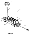
図1A及び図1Bを参照すると、プリントヘッド10は、積層体サブアセンブリ14に結合された本体12を含む。部品は、エポキシ等といった接着剤を用いて互いに結合され得る。プリントヘッド10に導入されるインクは、まず、フィルタ16及び管18を通り、本体12に形成されたインク返し20を介して本体12に入る。本体12には、本体12とサブアセンブリ14との間の空気圧を解放するための開口部22が形成されており、開口部22上にはシール24が配置されている。本体12の上部にはカバー26が取り付けられている。
With reference to FIGS. 1A and 1B, the
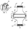
図2A及び図2Bは、プリントヘッド10の本体12及びサブアセンブリ14を示す。サブアセンブリ14の第1の層は圧電素子28であり、圧電素子28はフレキシブルプリント基板30に結合されている。本体12がサブアセンブリ14に結合されると、圧電素子28を環境から保護すると共にインク流路からシールするためのチャンバ32が形成される。
2A and 2B show the
図3を参照すると、サブアセンブリ14は、圧電素子28、フレキシブルプリント基板30、キャビティプレート34、ディセンダープレート36、音響吸収材38、スペーサ40及びオリフィスプレート42といった部品を含み、これらは一体に結合されている。これらの部品は、エポキシ等といった接着剤を用いて一体に結合され得る。
Referring to FIG. 3, the
図2Aを参照すると、インクはインク返し20を下に移動して本体12の底部側に至り、図2Cに示されるように、本体12に形成された流体マニホールド44に入る。インクは流体マニホールド44を満たし、フレキシブルプリント基板30の複数の開口部46を通って移動し、図3に示されるように、キャビティプレート34に形成された複数のポンプチャンバ48に入る。
Referring to FIG. 2A, the ink moves down the ink return 20 to the bottom side of the
図3を参照すると、圧電素子28が作動されると、ポンプチャンバ内のインクポンプチャンバの複数の開口部50を通って送り出され、ディセンダープレート36の複数の開口部52を通り、音響吸収材の複数の開口部(図示せず)38を通り、複数のスペーサ開口部54を通り、オリフィスプレート42のオリフィス56から出る。
Referring to FIG. 3, when the piezoelectric element 28 is actuated, the piezoelectric element 28 is sent out through the plurality of openings 50 of the ink pump chamber in the pump chamber, passes through the plurality of openings 52 of the descender plate 36, and the sound absorbing material Through a plurality of openings (not shown) 38, through a plurality of spacer openings 54, and exit the orifice 56 of the
図2Bは、本体12がサブアセンブリ14に結合された際に形成されるチャンバ32の断面図を示しており、サブアセンブリ14は、第1の層として圧電素子28を有する。チャンバ32は、圧電素子28を外部環境から保護する。本体12には、チャンバ32内の空気圧を解放するための開口部22が形成され、開口部22には、接着剤(即ち、エポキシ)を用いてシール24が結合される。シール24は、圧力下で形状が変わる柔軟な材料(即ち、ポリイミド)で作られ得る。
FIG. 2B shows a cross-sectional view of the chamber 32 formed when the
チャンバ32内の空気圧が上昇すると、シール24が接触している部分である開口部22の周囲に力が加わる。シール24に加わる力の量は、開口部22の半径の関数である。シール24を開口部22に結合させている接着剤は、或る圧力で開口部22の表面から分離されて空気圧を解放し、その後、再び接着する。接着剤が特定の空気圧で分離して再び接着するよう、特定の空気圧に合わせて開口部22の半径及び接着剤の強さを設計できる。
When the air pressure in the chamber 32 increases, a force is applied around the
図2Aには、本体12の開口部22の位置が本体12の表面より高くなっていることが示されている。開口部22の位置を高くすることにより、圧電素子28がインク漏れから保護されると共に、シール24によって、圧電素子28がインクや他の環境的要因から更に保護される。
FIG. 2A shows that the position of the opening 22 of the
図3を参照すると、フレキシブルプリント基板30の複数の開口部は、マニホールド44からポンプチャンバに至るインク流路を提供する。図4Aは、開口部46を通る流体との接触を回避するために開口部間のスペースに設けられた電気配線58を有するフレキシブルプリント基板30を示す。電気配線58は、フレキシブルプリント基板30の中心付近の(圧電素子に隣接した)電極から、フレキシブルプリント基板30の端部のコネクタ60へと延びている。コネクタ60の両側からはタブ62が延出しており、図1Aに示されるように、タブ62はカバー26にスナップ式に嵌る。
Referring to FIG. 3, the plurality of openings in the flexible printed
図4Bは、接着剤を用いて互いに結合された第1の層64及び第2の層66を有するフレキシブルプリント基板30を示す。時間が経つと、インクの影響により接着剤が2つの層から分離し、フレキシブルプリント基板30の内部でインクが漏れて、電気配線58に接触することがある。或る実施態様では、フレキシブルプリント基板30の2つの層はポリイミドでできており、接着剤もポリイミドを含有する。フレキシブルプリント基板30の層及び接着剤が同じ材料でできている場合には、インクが接着剤を2つの層から分離させる可能性は低くなる。フレキシブルプリント基板30の開口部は、ダイ、レーザ、又は他の類似の方法で切り抜くことができる。フレキシブルプリント基板30の開口部の縁部を、その中を流れる流体による劣化から保護するために、コーティング又は他の材料を用いることも可能である。
FIG. 4B shows a flexible printed
図3を参照すると、フレキシブルプリント基板30の複数の開口部は、キャビティプレート34のポンプチャンバと実際に位置が合っている一部の開口部にのみ、ポンプチャンバに至るインク流路を提供する。残りのポンプチャンバは、開口部間のスペースによってブロックされる。流れる先のポンプチャンバがブロックされているインクは、フレキシブルプリント基板30の開口部を通って、ブロックされていないポンプチャンバを通り、ディセンダープレート36の複数のチャネル68に至る。これらのチャネル68内のインクは、その上のキャビティプレート34に戻り、ブロックされているポンプチャンバに入る。
Referring to FIG. 3, the plurality of openings of the flexible printed
図3を参照すると、音響吸収材38が、Upilex(登録商標)ポリイミド等といったプラスチック材料でできている場合には、材料は均一に結合しないことがあり、未結合の材料領域が残り得る。より良好な結合のために、音響吸収材38に開口部70を切り抜くことができる。
Referring to FIG. 3, if the
本体12は、ポリフェニレンスルフィド(PPS)等といったプラスチック材料、又はアルミニウム等といった金属で作ることができる。カバー26は、金属又はDelrin(登録商標)アセタール等といったプラスチック材料で作ることができる。フレキシブルプリント基板30及び音響吸収材38は、「Upilex」ポリイミドで作ることができ、ディセンダープレート36及びキャビティプレート34は、Kovar(登録商標)合金等といった金属で作ることができる。スペーサ40は、カーボン(約7MPa)やポリイミド(約3MPa)等といった低弾性率材料で作ることができる。オリフィスプレート42はステンレス鋼で作ることができる。
The
積層体サブアセンブリ14内のオリフィスプレート42及び音響吸収材38を結合する際に、スペーサ40を用いることができる。オリフィスプレート42又は音響吸収材38に接着剤を直接塗布するのではなく、接着剤をスペーサの両面に直接塗布し、オリフィスプレート42及び音響吸収材38をスペーサに結合することができる。スペーサは、異なる熱膨張係数を有する積層体間でひずみを分配することもできる。例えば、異なる熱膨張係数を有する積層体が、約150℃の結合温度で互いに結合されると、積層体が室温(約22℃)まで冷却された際に、積層体は湾曲し得る。スペーサで結合のひずみを分配することにより、積層体サブアセンブリの湾曲を低減できる。スペーサの厚さ及び弾性率は、スペーサがサブアセンブリ内でひずみを分配する能力に影響し得る。スペーサのひずみの割合は、スペーサの厚さで割ったひずみの関数である。
A spacer 40 can be used in joining the
図2Cは、プリントヘッド10をラックアセンブリに固定する3つの偏心ねじを受容するための3つの穴72(本体12の一方の側に2つ、他方の側に1つ)を有する本体12を示す。
FIG. 2C shows the
図3を参照すると、各部品の端部にある開口部74を用いて、足りない部品及び部品の位置決めを確認できる。検査カメラで開口部74の中をのぞき、部品の位置決めを視覚的に検査する。圧電素子28上には基準マークが配置され、これは、全ての部品が適切に位置決めされた際に見えるようになっている。更に、プリントヘッド10の製造後又はメンテナンス時に、開口部74を通して目視検査を行うことで、全ての部品が存在し、部品が正しい順序になっていることを確実にできる。
Referring to FIG. 3, the missing parts and the positioning of the parts can be confirmed using the
他の実施態様では、本体及び積層体サブアセンブリを、接着剤、ねじ及び締め具等といった他の固定装置に取り付けることができる。サブアセンブリの部品は、他の材料や接着剤によって固定することも可能である。シール24は、他の接着剤によって本体の開口部に取り付けられることも可能である。図2A及び図2Bを参照すると、サブアセンブリと本体との間に圧電素子を保護するためのチャンバを形成する代わりに、コーティングによって圧電素子を保護することも可能である。図1Aには、プリントヘッド10のカバー26にスナップ式に嵌ったタブ62が示されているが、タブは、ねじ、留め具、接着剤又は他の固定具によってプリントヘッドに固定されてもよい。図3のフレキシブルプリント基板30では、フレキシブルプリント基板30の両側に複数の開口部が示されているが、フレキシブルプリント基板30は、一方の側のみに、インク経路用の1つ又は複数の開口部を有してもよい。同様に、図3のキャビティプレートでは、キャビティプレートの両側に複数のポンプチャンバが示されているが、キャビティプレートは、一方の側のみに1つ又は複数のポンプチャンバを有してもよい。
In other embodiments, the body and laminate subassembly can be attached to other fastening devices such as adhesives, screws and fasteners. The parts of the subassembly can also be fixed by other materials or adhesives. The
図1Aのコネクタ60は、タブ62を用いずに、カバー26に直接固定されてもよい。例えば、コネクタ60は、接着剤を用いてカバー26に接着されてもよい。
The connector 60 of FIG. 1A may be directly fixed to the
図4Aを参照すると、フレキシブルプリント基板30上の電気配線58は、開口部46を通って流れる流体が配線に接触するのを防止するためにシールされてもよい。例えば、図4Bの第1の層64はポリイミド材料(即ち、「Upilex」ポリイミド)であってもよく、電気配線は第1の層64上に形成されてもよく、第2の層66は、電気配線を覆うカバーレイであってもよい。カバーレイは、日本国の新日鐵化学株式会社(Nippon Steel Chemical)から入手可能なEspanex(登録商標)SPIスクリーンプリント可能ポリイミドカバーレイ等といった、プリント可能なポリイミドであってもよい。ポリイミドは、シルクスクリーンプリント法又は他の付着方法を用いて付着され得る。
Referring to FIG. 4A, the
図1Aを参照すると、プリントヘッド10の寸法は、約29.15mmの高さ、約115.9mmの長さ、及び約30.6mmの幅を有し得る。
With reference to FIG. 1A, the dimensions of the
図3を参照すると、積層体サブアセンブリ14は、タブ43を有し得る接地プレート41も含み得る。複数の積層体が一体に積み重ねられた場合には、図2Aに示されるように、サブアセンブリ14からタブ43が延出し、ハウジング12の上に折り返され得る。図1の接地線13は、接地プレート41のタブ43に接続している。
Referring to FIG. 3, the
再び図3を参照すると、積層体サブアセンブリ14を通って流れる流体は、接地プレート41の開口部55を通ってオリフィスプレート42のオリフィス56から出てもよい。接地プレート41は、サブアセンブリ14の他の積層体の開口部74と位置決めされる開口部74も有し得る。
Referring again to FIG. 3, the fluid flowing through the
他の実施態様も添付の特許請求の範囲に含まれる。 Other embodiments are within the scope of the appended claims.
10 プリントヘッド
12 本体
14 積層体サブアセンブリ
22 開口部
24 シール
28 圧電素子
30 フレキシブルプリント基板
32 チャンバ
34 キャビティプレート
36 ディセンダープレート
38 音響吸収材
40 スペーサ
41 接地プレート
42 オリフィスプレート
44 流体マニホールド
58 電気配線
74 開口部
DESCRIPTION OF
Claims (24)
前記本体に取り付けられたアクチュエータであって該アクチュエータと前記本体との間の囲まれた空間がチャンバを形成するアクチュエータと、
前記チャンバ内の圧力を解放するための、前記本体によって画成された開口部と、
圧力の解放を可能にしつつ前記チャンバをシールするための、前記開口部に取り付けられたシールと
を備えることを特徴とするプリントヘッド。 The body,
An actuator attached to the body, wherein an enclosed space between the actuator and the body forms a chamber;
An opening defined by the body for relieving pressure in the chamber;
A print head comprising: a seal attached to the opening for sealing the chamber while allowing release of pressure.
前記本体上に形成された電気配線と、
前記本体によって画成された、流体が通過するための複数の開口部と
を備えることを特徴とするフレキシブル回路。 A body made of a flexible material;
Electrical wiring formed on the body;
A flexible circuit comprising: a plurality of openings defined by the main body through which fluid passes.
各積層体が複数の開口部を有し、該開口部の検査に基づき、各積層体の開口部が他の積層体の開口部と位置決めされることを特徴とする積層体サブアセンブリ。 A laminate subassembly comprising a plurality of laminates comprising an actuator, a cavity plate, a descender plate and an orifice plate,
A laminate subassembly, wherein each laminate has a plurality of openings, and the openings of each laminate are positioned with the openings of the other laminate based on inspection of the openings.
前記複数の積層体の前記複数の開口部及び前記複数の積層体の1つの前記基準マークを用いて前記複数の積層体を位置決めする工程と、
前記複数の積層体を一体に取り付ける工程と、
前記開口部を検査して前記複数の積層体の位置決めを判定する工程と
を備えることを特徴とする複数の積層体の位置決め方法。 Providing a plurality of laminates including actuators, cavity plates, descender plates and orifice plates and having a plurality of openings, one of the laminates including a reference mark;
Positioning the plurality of laminates using the plurality of openings of the plurality of laminates and the one reference mark of the plurality of laminates;
Attaching the plurality of laminates integrally;
And a step of determining the positioning of the plurality of laminated bodies by inspecting the openings.
Applications Claiming Priority (2)
| Application Number | Priority Date | Filing Date | Title |
|---|---|---|---|
| US79615406P | 2006-04-28 | 2006-04-28 | |
| PCT/US2007/067506 WO2007127846A2 (en) | 2006-04-28 | 2007-04-26 | Printhead module |
Related Child Applications (2)
| Application Number | Title | Priority Date | Filing Date |
|---|---|---|---|
| JP2011254022A Division JP5173010B2 (en) | 2006-04-28 | 2011-11-21 | Printhead module |
| JP2011254023A Division JP5175970B2 (en) | 2006-04-28 | 2011-11-21 | Printhead module |
Publications (2)
| Publication Number | Publication Date |
|---|---|
| JP2009535239A true JP2009535239A (en) | 2009-10-01 |
| JP2009535239A5 JP2009535239A5 (en) | 2011-01-13 |
Family
ID=38656380
Family Applications (3)
| Application Number | Title | Priority Date | Filing Date |
|---|---|---|---|
| JP2009507954A Pending JP2009535239A (en) | 2006-04-28 | 2007-04-26 | Printhead module |
| JP2011254022A Active JP5173010B2 (en) | 2006-04-28 | 2011-11-21 | Printhead module |
| JP2011254023A Active JP5175970B2 (en) | 2006-04-28 | 2011-11-21 | Printhead module |
Family Applications After (2)
| Application Number | Title | Priority Date | Filing Date |
|---|---|---|---|
| JP2011254022A Active JP5173010B2 (en) | 2006-04-28 | 2011-11-21 | Printhead module |
| JP2011254023A Active JP5175970B2 (en) | 2006-04-28 | 2011-11-21 | Printhead module |
Country Status (7)
| Country | Link |
|---|---|
| US (2) | US8403460B2 (en) |
| EP (1) | EP2013023B1 (en) |
| JP (3) | JP2009535239A (en) |
| KR (1) | KR101422210B1 (en) |
| CN (3) | CN101432142B (en) |
| HK (2) | HK1126169A1 (en) |
| WO (1) | WO2007127846A2 (en) |
Families Citing this family (6)
| Publication number | Priority date | Publication date | Assignee | Title |
|---|---|---|---|---|
| CN101432142B (en) | 2006-04-28 | 2013-01-02 | 富士胶卷迪马蒂克斯股份有限公司 | Printhead module |
| JP4966829B2 (en) | 2007-11-16 | 2012-07-04 | 株式会社リコー | Liquid ejection head, ink cartridge, and image forming apparatus |
| JP5427730B2 (en) * | 2010-08-19 | 2014-02-26 | 東芝テック株式会社 | Ink jet print head and ink jet print head manufacturing method |
| US9908327B2 (en) * | 2014-04-23 | 2018-03-06 | Hewlett-Packard Development Company, L.P. | Printhead assembly |
| JP6451174B2 (en) * | 2014-09-24 | 2019-01-16 | セイコーエプソン株式会社 | Liquid ejection apparatus and liquid ejection method |
| SG11202112424TA (en) | 2019-05-30 | 2021-12-30 | Becton Dickinson Co | Cartridge adapter for drug delivery device |
Citations (1)
| Publication number | Priority date | Publication date | Assignee | Title |
|---|---|---|---|---|
| JP2005074966A (en) * | 2003-09-03 | 2005-03-24 | Seiko Epson Corp | Liquid injection head, liquid injection device and ventilation method of liquid injection head |
Family Cites Families (16)
| Publication number | Priority date | Publication date | Assignee | Title |
|---|---|---|---|---|
| GB9202434D0 (en) * | 1992-02-05 | 1992-03-18 | Xaar Ltd | Method of and apparatus for forming nozzles |
| JP3088890B2 (en) * | 1994-02-04 | 2000-09-18 | 日本碍子株式会社 | Piezoelectric / electrostrictive film type actuator |
| US5474032A (en) * | 1995-03-20 | 1995-12-12 | Krietzman; Mark H. | Suspended feline toy and exerciser |
| US6070965A (en) * | 1994-10-28 | 2000-06-06 | Rohm Co., Ltd. | Ink jet printhead with folded flexible cord, and nozzle plate used for the same |
| WO1999010179A1 (en) * | 1997-08-22 | 1999-03-04 | Xaar Technology Limited | Method of manufacture of printing apparatus |
| US6669781B2 (en) * | 1997-09-23 | 2003-12-30 | Micron Technology, Inc. | Method and apparatus for improving stencil/screen print quality |
| JPH11216861A (en) | 1998-02-02 | 1999-08-10 | Ricoh Co Ltd | Ink-jet head |
| JP3899639B2 (en) * | 1998-02-23 | 2007-03-28 | セイコーエプソン株式会社 | Piezoelectric element, ink jet recording head |
| US6322200B1 (en) * | 1999-10-29 | 2001-11-27 | Hewlett-Packard Company | Decoupled nozzle plate and electrical flexible circuit for an inkjet print cartridge |
| JP3818453B2 (en) | 2000-08-30 | 2006-09-06 | ブラザー工業株式会社 | Inkjet printer head and manufacturing method thereof |
| US6869273B2 (en) * | 2002-05-15 | 2005-03-22 | Hewlett-Packard Development Company, L.P. | Microelectromechanical device for controlled movement of a fluid |
| JP3951119B2 (en) * | 2002-06-26 | 2007-08-01 | ブラザー工業株式会社 | Inkjet printer head |
| JP4326772B2 (en) * | 2002-09-10 | 2009-09-09 | 株式会社リコー | Droplet discharge head, ink cartridge, and ink jet recording apparatus |
| GB2410463A (en) * | 2004-01-29 | 2005-08-03 | Hewlett Packard Development Co | A method of making an inkjet printhead |
| JP4581426B2 (en) | 2004-02-27 | 2010-11-17 | ブラザー工業株式会社 | Inkjet head |
| CN101432142B (en) | 2006-04-28 | 2013-01-02 | 富士胶卷迪马蒂克斯股份有限公司 | Printhead module |
-
2007
- 2007-04-26 CN CN2007800154811A patent/CN101432142B/en active Active
- 2007-04-26 KR KR1020087029060A patent/KR101422210B1/en active IP Right Grant
- 2007-04-26 EP EP07761353A patent/EP2013023B1/en active Active
- 2007-04-26 JP JP2009507954A patent/JP2009535239A/en active Pending
- 2007-04-26 CN CN2010101261496A patent/CN101797839B/en active Active
- 2007-04-26 WO PCT/US2007/067506 patent/WO2007127846A2/en active Application Filing
- 2007-04-26 CN CN201010126147A patent/CN101791904A/en active Pending
- 2007-04-27 US US11/741,325 patent/US8403460B2/en active Active
-
2009
- 2009-06-01 HK HK09104918.2A patent/HK1126169A1/en unknown
-
2011
- 2011-02-10 HK HK11101307.3A patent/HK1147229A1/en unknown
- 2011-11-21 JP JP2011254022A patent/JP5173010B2/en active Active
- 2011-11-21 JP JP2011254023A patent/JP5175970B2/en active Active
-
2013
- 2013-02-14 US US13/766,939 patent/US8608287B2/en active Active
Patent Citations (1)
| Publication number | Priority date | Publication date | Assignee | Title |
|---|---|---|---|---|
| JP2005074966A (en) * | 2003-09-03 | 2005-03-24 | Seiko Epson Corp | Liquid injection head, liquid injection device and ventilation method of liquid injection head |
Also Published As
| Publication number | Publication date |
|---|---|
| US20130155153A1 (en) | 2013-06-20 |
| EP2013023B1 (en) | 2012-05-30 |
| CN101797839B (en) | 2012-10-31 |
| EP2013023A4 (en) | 2010-01-27 |
| JP2012066593A (en) | 2012-04-05 |
| CN101797839A (en) | 2010-08-11 |
| JP5175970B2 (en) | 2013-04-03 |
| HK1147229A1 (en) | 2011-08-05 |
| WO2007127846A3 (en) | 2008-04-03 |
| CN101432142B (en) | 2013-01-02 |
| HK1126169A1 (en) | 2009-08-28 |
| JP2012086569A (en) | 2012-05-10 |
| CN101791904A (en) | 2010-08-04 |
| JP5173010B2 (en) | 2013-03-27 |
| WO2007127846A2 (en) | 2007-11-08 |
| US8608287B2 (en) | 2013-12-17 |
| EP2013023A2 (en) | 2009-01-14 |
| US20070252874A1 (en) | 2007-11-01 |
| KR20090009919A (en) | 2009-01-23 |
| CN101432142A (en) | 2009-05-13 |
| KR101422210B1 (en) | 2014-07-30 |
| US8403460B2 (en) | 2013-03-26 |
Similar Documents
| Publication | Publication Date | Title |
|---|---|---|
| JP5175970B2 (en) | Printhead module | |
| US8205971B2 (en) | Electrically grounded inkjet ejector and method for making an electrically grounded inkjet ejector | |
| US7585060B2 (en) | Liquid ejecting head and liquid ejecting apparatus | |
| JP4254826B2 (en) | Manufacturing method of head unit | |
| JP2017109476A (en) | Ink jet head and ink jet recording device | |
| US20100263791A1 (en) | Fluid dispensing subassembly with compliant film | |
| JP4765510B2 (en) | Liquid ejecting apparatus and manufacturing method thereof | |
| US8388778B2 (en) | Print head with reduced bonding stress and method | |
| JP2006116954A (en) | Liquid ejecting apparatus, manufacturing method for liquid ejecting apparatus and inkjet printer | |
| JP2017213845A (en) | Liquid jet head and liquid jet device | |
| JP4923826B2 (en) | Droplet discharge head and droplet discharge apparatus | |
| JP6733669B2 (en) | Inkjet head and inkjet recording device | |
| JP4941021B2 (en) | Liquid jet head | |
| JP2007245394A (en) | Inkjet printer head and its manufacturing method | |
| JP2007001192A (en) | Manufacturing method for head module, manufacturing method for liquid delivering head, and manufacturing method for liquid delivering apparatus | |
| JP2011218641A (en) | Ink jet head | |
| JP2013176849A (en) | Inkjet head | |
| JP6825713B2 (en) | Inkjet head and inkjet recorder | |
| JP2004188687A (en) | Inkjet head and inkjet recording apparatus | |
| JP2004142296A (en) | Inkjet head and inkjet-type recording device | |
| WO2017169548A1 (en) | Inkjet head and inkjet recording apparatus | |
| JP2007062260A (en) | Head module, liquid delivering head, liquid delivering apparatus, and method of manufacturing head module | |
| JP2012218211A (en) | Liquid ejection head, liquid ejecting apparatus, and method of manufacturing liquid ejection head |
Legal Events
| Date | Code | Title | Description |
|---|---|---|---|
| A521 | Written amendment |
Free format text: JAPANESE INTERMEDIATE CODE: A523 Effective date: 20100426 |
|
| A621 | Written request for application examination |
Free format text: JAPANESE INTERMEDIATE CODE: A621 Effective date: 20100426 |
|
| A521 | Written amendment |
Free format text: JAPANESE INTERMEDIATE CODE: A523 Effective date: 20101112 |
|
| A131 | Notification of reasons for refusal |
Free format text: JAPANESE INTERMEDIATE CODE: A131 Effective date: 20110719 |
|
| A601 | Written request for extension of time |
Free format text: JAPANESE INTERMEDIATE CODE: A601 Effective date: 20111013 |
|
| A602 | Written permission of extension of time |
Free format text: JAPANESE INTERMEDIATE CODE: A602 Effective date: 20111020 |
|
| A02 | Decision of refusal |
Free format text: JAPANESE INTERMEDIATE CODE: A02 Effective date: 20120131 |