JP2009535093A - Embedded electroactive polymer structure for use in medical devices - Google Patents
Embedded electroactive polymer structure for use in medical devices Download PDFInfo
- Publication number
- JP2009535093A JP2009535093A JP2009507679A JP2009507679A JP2009535093A JP 2009535093 A JP2009535093 A JP 2009535093A JP 2009507679 A JP2009507679 A JP 2009507679A JP 2009507679 A JP2009507679 A JP 2009507679A JP 2009535093 A JP2009535093 A JP 2009535093A
- Authority
- JP
- Japan
- Prior art keywords
- electroactive polymer
- polymer
- matrix material
- layer
- embedded
- Prior art date
- Legal status (The legal status is an assumption and is not a legal conclusion. Google has not performed a legal analysis and makes no representation as to the accuracy of the status listed.)
- Pending
Links
Images


Classifications
-
- A—HUMAN NECESSITIES
- A61—MEDICAL OR VETERINARY SCIENCE; HYGIENE
- A61L—METHODS OR APPARATUS FOR STERILISING MATERIALS OR OBJECTS IN GENERAL; DISINFECTION, STERILISATION OR DEODORISATION OF AIR; CHEMICAL ASPECTS OF BANDAGES, DRESSINGS, ABSORBENT PADS OR SURGICAL ARTICLES; MATERIALS FOR BANDAGES, DRESSINGS, ABSORBENT PADS OR SURGICAL ARTICLES
- A61L29/00—Materials for catheters, medical tubing, cannulae, or endoscopes or for coating catheters
- A61L29/14—Materials characterised by their function or physical properties, e.g. lubricating compositions
- A61L29/146—Porous materials, e.g. foams or sponges
-
- F—MECHANICAL ENGINEERING; LIGHTING; HEATING; WEAPONS; BLASTING
- F03—MACHINES OR ENGINES FOR LIQUIDS; WIND, SPRING, OR WEIGHT MOTORS; PRODUCING MECHANICAL POWER OR A REACTIVE PROPULSIVE THRUST, NOT OTHERWISE PROVIDED FOR
- F03G—SPRING, WEIGHT, INERTIA OR LIKE MOTORS; MECHANICAL-POWER PRODUCING DEVICES OR MECHANISMS, NOT OTHERWISE PROVIDED FOR OR USING ENERGY SOURCES NOT OTHERWISE PROVIDED FOR
- F03G7/00—Mechanical-power-producing mechanisms, not otherwise provided for or using energy sources not otherwise provided for
- F03G7/005—Electro-chemical actuators; Actuators having a material for absorbing or desorbing gas, e.g. a metal hydride; Actuators using the difference in osmotic pressure between fluids; Actuators with elements stretchable when contacted with liquid rich in ions, with UV light, with a salt solution
-
- A—HUMAN NECESSITIES
- A61—MEDICAL OR VETERINARY SCIENCE; HYGIENE
- A61M—DEVICES FOR INTRODUCING MEDIA INTO, OR ONTO, THE BODY; DEVICES FOR TRANSDUCING BODY MEDIA OR FOR TAKING MEDIA FROM THE BODY; DEVICES FOR PRODUCING OR ENDING SLEEP OR STUPOR
- A61M25/00—Catheters; Hollow probes
- A61M25/0043—Catheters; Hollow probes characterised by structural features
- A61M2025/0058—Catheters; Hollow probes characterised by structural features having an electroactive polymer material, e.g. for steering purposes, for control of flexibility, for locking, for opening or closing
Landscapes
- Chemical & Material Sciences (AREA)
- Engineering & Computer Science (AREA)
- Combustion & Propulsion (AREA)
- Health & Medical Sciences (AREA)
- Veterinary Medicine (AREA)
- Animal Behavior & Ethology (AREA)
- General Health & Medical Sciences (AREA)
- Public Health (AREA)
- Life Sciences & Earth Sciences (AREA)
- Analytical Chemistry (AREA)
- Epidemiology (AREA)
- Dispersion Chemistry (AREA)
- Mechanical Engineering (AREA)
- General Engineering & Computer Science (AREA)
- Materials For Medical Uses (AREA)
- Prostheses (AREA)
- Surgical Instruments (AREA)
Abstract
医療装置またはその構成要素は、医療装置またはその構成要素の少なくとも一部内に埋設された電気活性ポリマーアクチュエータを有する。新規な電気活性ポリマーアクチュエータは、導電基材層および電気活性ポリマー層によって形成されている。電気活性ポリマーは、周囲の液体電解質への電圧の印加により作動させられる。アクチュエータは、不活性ポリマーマトリックス材料、または固体高分子電解質マトリックス材料内に埋設され得る。 The medical device or component thereof has an electroactive polymer actuator embedded within at least a portion of the medical device or component thereof. The novel electroactive polymer actuator is formed by a conductive substrate layer and an electroactive polymer layer. The electroactive polymer is activated by the application of a voltage to the surrounding liquid electrolyte. The actuator can be embedded in an inert polymer matrix material or a solid polyelectrolyte matrix material.
Description
本発明は、体内への埋め込み用または挿入用医療装置、特に少なくとも一部に導電性ポリマー構造を備えたそのような医療装置の分野に関する。 The present invention relates to the field of medical devices for implantation or insertion into the body, in particular such medical devices with a conductive polymer structure at least in part.
バルーンカテーテルの先端に位置する拡張可能なバルーン部材を有するバルーンカテーテルアセンブリを含むカテーテルアセンブリは、動脈の内膜の狭窄を生じるアテローム斑を圧縮するための膨張装置としてや、体内管内の病変部位、すなわち血管閉塞部に対するステントのような人工器官の搬送および拡張のためを含む様々な医学的処置において用いられる。 A catheter assembly, including a balloon catheter assembly having an expandable balloon member located at the distal end of the balloon catheter, can be used as an inflation device for compressing atherosclerotic plaques that cause stenosis of the arterial intima, It is used in a variety of medical procedures, including for the delivery and expansion of prostheses such as stents to vascular occlusions.
バルーンカテーテルが用いられる一つの医学的処置は、末梢動脈および冠動脈を治療する非侵襲性の非外科的手段である経皮経管冠動脈形成術(PTCA)、または単純旧式バルーン血管形成術(POBA)である。この技術は、冒された動脈に未膨張のバルーンカテーテルを挿入することから成る。動脈の罹患部の拡張は、アテローム性動脈硬化性病変を外側に押圧するバルーンを膨張させ、それにより動脈径を拡張することによって行われる。 One medical procedure in which balloon catheters are used is percutaneous transluminal coronary angioplasty (PTCA), which is a non-invasive non-surgical means of treating peripheral and coronary arteries, or simple old-fashioned balloon angioplasty (POBA) It is. This technique consists of inserting an uninflated balloon catheter into the affected artery. Expansion of the affected area of the artery is performed by inflating a balloon that presses the atherosclerotic lesion outward, thereby expanding the arterial diameter.
血管形成術の最も広く用いられている形態において、バルーンカテーテルは、カテーテルシャフトの先端に保持されたバルーンが狭窄または病変、すなわち血管閉塞部を越えて配置されるまで、脈管系内を通って案内される。次に、バルーンを膨張させて閉塞部に圧力を加えることにより、血管が開放されて血流が改善される。 In the most widely used form of angioplasty, the balloon catheter passes through the vasculature until the balloon held at the tip of the catheter shaft is placed beyond the stenosis or lesion, ie, the vascular occlusion. Guided. Next, by inflating the balloon and applying pressure to the obstruction, the blood vessels are opened and blood flow is improved.
一部の実施形態において、カテーテルバルーンは、ステントのような拡張可能な医療装置を拡張するため、かつ/または埋め込むために用いられ得る。バルーンが拡張されると、バルーン上に位置する医療装置またはステントも拡張され、解放されて、血管壁の支持および/または修復を支援する。 In some embodiments, the catheter balloon can be used to expand and / or implant an expandable medical device such as a stent. As the balloon is expanded, the medical device or stent located on the balloon is also expanded and released to assist with vessel wall support and / or repair.
血管の大きさが非常に小さく、またそのような装置は蛇行した経路を通って挿入および/または埋め込まれるため、そのようなアセンブリに対する望ましい特性としては、体内管を介して前進させ易くするための可撓性および操作性(操縦性)だけでなく、ロープロファイルを維持しながらの、薄い壁、高い強度および耐久性が挙げられる。また、半径方向の膨張特性および長手方向の膨張特性の双方を含む、様々な圧力に対する膨張時の医療用バルーンにおける寸法変化を制御することが望ましい。このように、他の装置特性を損なうことなく、装置サイズの規模を縮小する傾向にある。 Because the size of the blood vessel is very small and such devices are inserted and / or implanted through tortuous pathways, a desirable property for such assemblies is to facilitate advancement through body vessels. Not only flexibility and operability (maneuverability) but also thin walls, high strength and durability while maintaining a low profile. It is also desirable to control dimensional changes in the medical balloon during inflation for various pressures, including both radial and longitudinal inflation characteristics. In this way, the device size tends to be reduced without impairing other device characteristics.
導電性ポリマーを、操作可能であり、かつ周囲の受動的構造に伝えられ得る機械的特性を有する能動的構造として使用することは、挿入型および/または埋め込み型医療装置に有用であり得る。 The use of conductive polymers as active structures that are operable and have mechanical properties that can be transferred to surrounding passive structures can be useful for insertable and / or implantable medical devices.
一態様において、本発明は医療装置における電気活性ポリマー(EAP)活性領域(アクチュエータ)の使用に関する。前記活性領域は、マトリックス材料中に埋設されて、医療装置またはその構成要素の可撓性、操作性、操縦性、耐久性、および強度を向上させる。 In one aspect, the invention relates to the use of an electroactive polymer (EAP) active region (actuator) in a medical device. The active area is embedded in the matrix material to improve the flexibility, operability, maneuverability, durability, and strength of the medical device or its components.
一態様において、本発明は、EAP活性領域の一部を形成する固体高分子電解質マトリックス内におけるEAPの埋設に関する。
別の態様において、本発明は、固体非活性ポリマーマトリックス内におけるEAP活性領域の埋設に関する。
In one aspect, the invention relates to the embedding of EAP within a solid polyelectrolyte matrix that forms part of the EAP active region.
In another aspect, the invention relates to embedding EAP active regions within a solid non-active polymer matrix.
本願においては、非活性(inactive)ポリマーマトリックスという用語は、不活性(inert)または受動的な(passive)ポリマー材料を指すために用いられるものとする。そのようなポリマー材料は、EAPの作動に能動的に関与しない。例えば、導電性を付与するために修飾されていないポリオレフィンまたは他の不活性ポリマー材料は、非活性ポリマー材料であり、EAP活性領域の一部を形成しない。そのような材料は、続くべき詳細な説明において、より詳細に検討するものとする。 In this application, the term inactive polymer matrix shall be used to refer to inert or passive polymer material. Such polymeric materials are not actively involved in EAP operation. For example, a polyolefin or other inert polymer material that has not been modified to impart electrical conductivity is a non-active polymer material that does not form part of the EAP active region. Such materials will be discussed in more detail in the detailed description that follows.
したがって、本発明によれば、マトリックス材料は、EAP活性領域の一部を形成してもよいし、形成しなくてもよい。
EAPは、膜、繊維、繊維の束、粒子などの形態にあるマトリックス材料内に埋設され得る。
Thus, according to the present invention, the matrix material may or may not form part of the EAP active region.
EAP can be embedded in a matrix material in the form of membranes, fibers, fiber bundles, particles, and the like.
電気活性ポリマー活性領域は、医療装置の少なくとも一部を形成する非活性マトリックス材料内に埋設されてもよい。そのような実施形態において、電気活性ポリマーの作動は、固体高分子電解質ではなく流体イオン交換に依存し得る。 The electroactive polymer active region may be embedded in a non-active matrix material that forms at least a portion of the medical device. In such embodiments, electroactive polymer operation may rely on fluid ion exchange rather than solid polyelectrolytes.
そのような実施形態において、非活性ポリマーマトリックスは、周囲の流体からEAP材料へのイオンのより良好なアクセスを可能にする空隙のような表面構造を備え得る。そのような構造を備えることによって、EAP作動の速度を向上することができる。 In such embodiments, the non-active polymer matrix may comprise a surface structure such as a void that allows better access of ions from the surrounding fluid to the EAP material. By providing such a structure, the speed of the EAP operation can be improved.
本発明は、さらにEAP、金属、および液体環境に由来するイオンを含む活性領域用の構造を提供する。EAP活性領域は、導電層およびEAP層を備える。前記イオンは電解質を含む周囲流体に由来し得る。EAP構造は非活性ポリマーマトリックス内に埋設される。この構造は、該構造がEAPのより大きな表面積に対して電気伝導性拡散(electrical conductive diffusion)を可能にするときに、より速い活性化を提供することが判明した。 The present invention further provides a structure for the active region that includes ions from EAP, metal, and liquid environments. The EAP active region comprises a conductive layer and an EAP layer. The ions may come from the surrounding fluid that contains the electrolyte. The EAP structure is embedded in a non-active polymer matrix. This structure has been found to provide faster activation when it allows for electrical conductive diffusion for the larger surface area of EAP.
本願に記載するEAP活性領域は、任意の種類の医療装置、特に体内管腔内に挿入可能および/または埋め込み可能である医療装置において用いられ得る。
本願に記載するEAP活性領域は、とりわけ、医療装置または該装置の諸態様の特性を制御する改善された能力を提供する。
The EAP active regions described herein can be used in any type of medical device, particularly medical devices that are insertable and / or implantable within a body lumen.
The EAP active regions described herein provide, among other things, an improved ability to control the characteristics of medical devices or aspects of the devices.
詳細な説明において検討される様々な実施形態において、EAP活性領域は、内側シャフトおよび外側シャフト、チップ、シースおよび拡張可能なバルーン部材を備えるカテーテルアセンブリの選択部分の壁内に埋設される。 In various embodiments discussed in the detailed description, the EAP active region is embedded within the walls of selected portions of the catheter assembly comprising inner and outer shafts, tips, sheaths and expandable balloon members.
本発明は、医療装置または医療装置の構成要素の少なくとも一部を形成するマトリックス材料内に埋設された電気活性ポリマー(EAP)アクチュエータの使用に関する。本願に記載するEAPアクチュエータは、任意の種類の医療装置、特に体内管腔内に挿入可能かつ/または埋め込み可能である医療装置に用いられ得る。本願に記載する本発明が用いられ得る医療装置の特定の例としては、様々な医学的処置のために用いられるカテーテルアセンブリおよび該カテーテルアセンブリの構成要素が挙げられる。カテーテルアセンブリの例としては、ガイドカテーテル、血管形成術用のPTAおよびPTCAカテーテルの
ようなバルーンカテーテル、前立腺治療用カテーテル、胃腸における使用のためのTTS内視鏡カテーテル、シングル・オペレーター・エクスチェンジまたはラピッド・エクスチェンジ(SOEまたはRX)カテーテル、オーバー・ザ・ワイヤー(OTW)カテーテル、固定ワイヤーカテーテル、自己拡張型およびバルーン拡張型の双方のステント搬送装置を含む医療装置搬送カテーテル、大静脈フィルタの搬送用カテーテル、経皮的卵円孔開存(PFO)閉鎖装置の搬送用カテーテル、治療物質送達装置、血栓摘出装置、内視鏡装置、血管造影用カテーテル、神経カテーテル、ディリテーション(dilitation)カテーテル、尿路カテーテル、胃腸用カテーテル装置、サーマルカテーテルと冷却装置(cooling)、脈管内超音波システム、電気生理学装置などとを備える熱伝導カテーテルなどが挙げられるが、これらに限定されるものではない。上記の列挙は、例示を目的としているに過ぎず、本発明の範囲を限定するものではない。上記の列挙は、例示を目的としているに過ぎず、本発明の範囲を限定するものではない。
The present invention relates to the use of electroactive polymer (EAP) actuators embedded in a matrix material that forms at least a portion of a medical device or a component of a medical device. The EAP actuators described herein can be used in any type of medical device, particularly medical devices that can be inserted and / or implanted in a body lumen. Particular examples of medical devices in which the invention described herein can be used include catheter assemblies used for various medical procedures and components of the catheter assemblies. Examples of catheter assemblies include guide catheters, balloon catheters such as PTA and PTCA catheters for angioplasty, prostate treatment catheters, TTS endoscopic catheters for use in the gastrointestinal tract, single operator exchange or rapid Exchange (SOE or RX) catheter, over-the-wire (OTW) catheter, fixed wire catheter, medical device delivery catheter including both self-expandable and balloon-expandable stent delivery devices, catheters for delivery of vena cava filters, Percutaneous patent foramen ovale (PFO) closure device transport catheter, therapeutic substance delivery device, thrombectomy device, endoscopic device, angiographic catheter, neurocatheter, dilation catheter , Urinary catheters, gastrointestinal catheter device, thermal catheter and cooling (Cooling), intravascular ultrasound systems, such as heat conduction catheter comprising a like electrophysiology devices including, but not limited thereto. The above list is for illustrative purposes only and is not intended to limit the scope of the present invention. The above list is for illustrative purposes only and is not intended to limit the scope of the present invention.
電気活性ポリマーは、該ポリマーの電気的刺激に応答して拡張および収縮する能力、すなわち体積変化によって特徴付けられる。EAPは、電子EAP(電界によって駆動)およびイオン性EAP(イオンの拡散による移動性または駆動を伴う)を含む2つのカテゴリーに分類することができる。 Electroactive polymers are characterized by their ability to expand and contract in response to electrical stimulation, ie volume change. EAP can be divided into two categories, including electronic EAP (driven by an electric field) and ionic EAP (with mobility or drive by diffusion of ions).
電子EAP(電気制限性物質(electrorestrictive)、静電体(electrostatic)、圧電性物質(piezoelectric)、強誘電体(ferroelectric))は、印加電界によって、それらの寸法の変化を誘発される。このカテゴリーの材料の例としては、強誘電性ポリマー(例えば、一般に知られているポリフッ化ビニリデンおよびナイロン11)、誘電性EAP、電気制限性グラフトエラストマーおよび電気粘弾性エラストマーのような電気制限性ポリマー、並びに液晶エラストマー複合材料が挙げられ、それらの材料の網目構造内に導電性ポリマーが分散される。 Electronic EAP (electrorestrictive material, electrostatic material, piezoelectric material, ferroelectric material) is induced to change their dimensions by an applied electric field. Examples of materials in this category include electrically restrictive polymers such as ferroelectric polymers (eg, commonly known polyvinylidene fluoride and nylon 11), dielectric EAP, electrically restrictive graft elastomers and electroviscoelastic elastomers. , As well as liquid crystal elastomer composites, in which the conductive polymer is dispersed within the network structure of these materials.
本発明に関しては、典型的にはイオン性EAPが用いられる。イオン性EAPとしては、イオン性ポリマーゲル、イオノマーポリマー−金属複合材、導電性ポリマーおよびカーボンナノチューブ複合材料が挙げられる。 For the present invention, typically ionic EAP is used. Ionic EAPs include ionic polymer gels, ionomer polymer-metal composites, conductive polymers and carbon nanotube composites.
電子EAPおよびイオン性EAPの双方の誘発変位は、屈曲、伸張、収縮、または回転するように幾何学的に設計され得る。
ポリエチレン、ポリスチレン、ポリプロピレンなどのような一般的なポリマー材料は、ポリマーマトリックス内に導電性の電流通過路を形成することにより、ポリマーに導電性を与える導電性充填材の添加を伴う配合技術によって導電性にされ得る。ポリマーマトリックスは絶縁性であるが、複合材は充填材によって導電性を示す。これらのポリマーは、ほとんど独占的に熱可塑性であるが、エポキシのような熱硬化性材料も用いられてもよい。適当な導電性充填材としては、金属および炭素(通常、カーボンブラック、または炭素繊維)が挙げられる。これらはスパッタコーティングの形態にあってもよいし、または導電性材料のパターンを適用し得る他の手段を用いてもよい。
The induced displacement of both electronic EAP and ionic EAP can be geometrically designed to bend, stretch, contract, or rotate.
Common polymer materials such as polyethylene, polystyrene, polypropylene, etc. are conductive by compounding techniques with the addition of conductive fillers that render the polymer conductive by forming conductive current paths in the polymer matrix. Can be made sex. The polymer matrix is insulative, but the composite material is conductive due to the filler. These polymers are almost exclusively thermoplastic, but thermosetting materials such as epoxies may also be used. Suitable conductive fillers include metals and carbon (usually carbon black or carbon fiber). These may be in the form of sputter coatings or other means that may apply a pattern of conductive material.
イオン性ポリマーゲルは化学反応によって活性化され、酸環境からアルカリ環境への変化によって、膨張し得る。
イオノマーポリマー−金属複合材は、ポリマーの網目構造におけるカチオンの移動性の結果として、屈曲し得る。適当なベースポリマーの例としては、パーフルオロスルホネートおよびパーフルオロカルボキシレートが挙げられるが、これらに限定されるものではない。
The ionic polymer gel is activated by a chemical reaction and can swell by a change from an acid environment to an alkaline environment.
Ionomer polymer-metal composites can bend as a result of cation mobility in the polymer network. Examples of suitable base polymers include, but are not limited to perfluorosulfonate and perfluorocarboxylate.
本質的に、本発明の様々な活性領域に関して、上記に列記したあらゆるものを含む、収縮性または拡張性を示す任意の電気活性ポリマーが用いられ得る。
本願の一部の実施形態において、イオン性EAPは、共役骨格(それらは、交互に連続した炭素−炭素単結合および炭素−炭素二重結合と、時折、炭素−窒素結合、すなわちπ−共役とを有する骨格を備える)を特徴とし、酸化下または還元下において電気伝導性を増大する能力を有する導電性ポリマーである。これらのポリマーは電子の移動の自由を許容し、従って該ポリマーが導電性になることを可能にする。パイ共役ポリマーは、酸化(p−ドーピング)または還元(n−ドーピング)によって、電気伝導性材料に変換される。
Essentially any electroactive polymer that exhibits contractility or expandability can be used, including anything listed above for the various active regions of the present invention.
In some embodiments of the present application, ionic EAPs are conjugated backbones (which are alternating carbon-carbon single bonds and carbon-carbon double bonds, and sometimes carbon-nitrogen bonds, i.e., π-conjugates. A conductive polymer having the ability to increase electrical conductivity under oxidation or reduction. These polymers allow freedom of electron movement and thus allow the polymer to become conductive. The pi-conjugated polymer is converted to an electrically conductive material by oxidation (p-doping) or reduction (n-doping).
単一の理論に拘束されるものではないが、導電性ポリマー(CP)は、酸化還元サイクル中に生じる可逆的な対イオンの挿入および脱離を介して作動する。寸法または体積の変化は、ポリマー中への、またはポリマーからのイオンの物質移動を介してもたらされ得る。このイオン移動を用いて、導電性ポリマーアクチュエータを形成する。EAP含有活性領域は、該活性領域から、または該活性領域へのイオンの流動に応答して、収縮および/または拡張する。例えば、一部の導電性ポリマーにおいては、拡張は鎖の間へのイオン挿入によるものと考えられるが、他のものにおいては、鎖間の斥力が主要な効果であると考えられる。この機構にかかわらず、材料中への、および材料からのイオンの物質移動は、ポリマーの拡張または収縮をもたらし、有意な応力(例えば約1MPaのオーダー)および歪み(すなわち最大約30%)を生じる。これらの特性は本発明の装置の構築にとって理想的である。本願においては、装置の活性領域の拡張または収縮は、概して「作動」と呼ばれる。これらの交換は小さな印加電圧によって生じ、電圧の変動を利用して作動速度を制御することができる。 Without being bound by a single theory, the conducting polymer (CP) operates through reversible counterion insertion and elimination that occurs during the redox cycle. The change in dimensions or volume can be effected through mass transfer of ions into or out of the polymer. This ion transfer is used to form a conductive polymer actuator. The EAP-containing active region contracts and / or expands in response to ion flow from or to the active region. For example, in some conductive polymers, expansion is thought to be due to ion insertion between the chains, while in others, repulsion between chains is considered to be a major effect. Regardless of this mechanism, mass transfer of ions into and out of the material results in polymer expansion or contraction, resulting in significant stress (eg, on the order of about 1 MPa) and strain (ie, up to about 30%). . These characteristics are ideal for the construction of the device of the present invention. In this application, the expansion or contraction of the active area of the device is generally referred to as “actuation”. These exchanges occur with a small applied voltage, and voltage fluctuations can be used to control the operating speed.
1ボルトまたは2ボルトほどの小さな電圧の印加および基材の適切な設計によって、イオン性EAPは有意に屈曲し得る。イオン性EAPはまた、それらを本発明の装置における使用に対して魅力あるものにする、下記の特性、すなわち、(a)軽量であり、可撓性であり、小さく、かつ製造が容易である、(b)制御するのが容易なエネルギー源が利用可能であり、エネルギーを容易にEAPSに伝えることができる、(c)電位の小さな変化(例えば1ボルトのオーダーの電位の変化;d)を用いて、EAPにおける体積変化をもたらすことができる、(e)作動が比較的速い(例えば、2、3秒で完全に拡張/収縮)、(f)EAP領域は、様々な技術、例えば電着を用いて形成することができる、(g)所望により、EAP領域は、例えばフォトリソグラフィーを用いて、パターニングを行うことができるといったことを含む多数の付加的な特性を有する。 By applying a voltage as low as 1 or 2 volts and proper design of the substrate, ionic EAP can be significantly bent. Ionic EAPs also make them attractive for use in the devices of the present invention: (a) light weight, flexible, small and easy to manufacture (B) an energy source that is easy to control is available and energy can be easily transferred to the EAPS; (c) a small change in potential (eg a change in potential on the order of 1 volt; d) Can be used to produce volume changes in EAP, (e) relatively fast in operation (eg, fully expanded / contracted in a few seconds), (f) EAP region can be used in various techniques such as electrodeposition (G) Optionally, the EAP region has a number of additional properties including, for example, that it can be patterned using photolithography.
いくつかの一般に知られている導電性EAPSとしては、ポリピロール、ポリアニリン、ポリチオフェン、ポリエチレンジオキシチオフェン、ポリ(p−フェニレン)、ポリ(p−フェニレンビニレン)、ポリスルホン、ポリピリジン、ポリキノキサリン、ポリアセチレン、ポリアントラキノン(polyanthraqinones)、ポリ(n−ビニルカルバゾール)などが挙げられ、最も一般的なものはポリチオフェン、ポリアニリンおよびポリピロールであるが、これらに限定されるものではない。 Some commonly known conductive EAPS include polypyrrole, polyaniline, polythiophene, polyethylene dioxythiophene, poly (p-phenylene), poly (p-phenylene vinylene), polysulfone, polypyridine, polyquinoxaline, polyacetylene, poly Examples include anthraquinones, poly (n-vinylcarbazole), and the most common are polythiophene, polyaniline, and polypyrrole, but are not limited thereto.
その構造のいくつかを下記に示す。 Some of the structures are shown below.

導電性ポリマーの網状組織を用いてもよい。例えば、ポリ(塩化ビニル)、ポリ(ビニルアルコール)、NAFION(登録商標)、すなわちデラウェア州ウィルミントン所在のイー.アイ.デュポン社(E. I. DuPont Co., Inc.)から入手可能である、少ない割合のスルホンイオン性官能基(sulfonic ionic functional groups)またはカルボキシイオン性官能基(carboxylic ionic functional groups)を含有するパーフルオロポリマーのような電気活性高分子網目中において、ピロールを重合することが知られている。 A network of conductive polymer may be used. For example, poly (vinyl chloride), poly (vinyl alcohol), NAFION®, i.e. E.I., located in Wilmington, Delaware. Eye. A small percentage of sulfonic or carboxylic functional groups available from EI DuPont Co., Inc. It is known to polymerize pyrrole in electroactive polymer networks such as fluoropolymers.
電気活性ポリマーはまた、本発明の譲受人に譲渡された同時係属中の米国特許公開第2005/0165439号で詳細に検討されている。前記文献の全容は、引用により本願に援用される。 Electroactive polymers are also discussed in detail in co-pending US Patent Publication No. 2005/0165439, assigned to the assignee of the present invention. The entire contents of the above documents are incorporated herein by reference.
加えて、電気活性ポリマー(EAP)の作動をもたらすためには、以下の構成要素、ずなわち、(a)電源(すなわちバッテリー)、(b)電気活性ポリマーを含む活性領域、(c)対向電極、(d)活性領域および対向電極の双方に接触した電解質が一般に用いられる。これは、以下の図面によってより詳細に示されるであろう。 In addition, to effect the operation of the electroactive polymer (EAP), the following components: (a) power source (ie battery), (b) active region containing the electroactive polymer, (c) facing An electrolyte in contact with both the electrode, (d) the active region and the counter electrode is generally used. This will be shown in more detail by the following figures.
更に、本願に記載した共役ポリマーのような導電性ポリマーの挙動は、電荷移動剤、すなわちイオンまたはドーパントの添加によって劇的に変えることができる。大きな非移動性アニオン(p−ドーピング)および大きな非移動性カチオン(n−ドーピング)を含む様々なドーパントが、ポリピロール含有活性領域のようなEAP含有活性領域において用いられ得る。これらの物質は、アニオン性ドーパント種でドープすることによってp型ドープ材料に酸化され、カチオン性ドーパント種でドープすることによってn−型ドープ材料に還元され得る。一般に、ポリピロール(PPy)のようなポリマーは部分的に酸化されて、p−ドープ材料を生成する。 Furthermore, the behavior of conducting polymers, such as the conjugated polymers described herein, can be dramatically altered by the addition of charge transfer agents, ie ions or dopants. Various dopants can be used in EAP-containing active regions, such as polypyrrole-containing active regions, including large non-mobile anions (p-doping) and large non-mobile cations (n-doping). These materials can be oxidized to a p-type doped material by doping with an anionic dopant species and reduced to an n-type doped material by doping with a cationic dopant species. In general, polymers such as polypyrrole (PPy) are partially oxidized to produce p-doped materials.
活性部材12の拡張または収縮は、それぞれ、これらのイオンの活性部材12への移動(ドーピング)、およびこれらのイオンの同部材からの移動(脱ドーピング)の結果である。図2は、アノード電圧およびカソード電圧を印加した際の、活性部材12中への、および同部材からのアニオンの移動を示す簡単な概略図である。この実施形態において、アノード電圧を印加してアニオンを活性部材12内に流入させると、活性部材12は拡張、この実施形態においては伸長、する。これに代わって、カソード電圧を印加して活性部材12からアニオンを流出させると、活性部材12は、収縮、この実施形態においては短縮、する。活性部材12へのアニオンの移動は、当業においては、ドーピングと称され、活性部材12からのアニオンの移動は脱ドーピング(de−doping)と称され得る。これらのイオン、すなわちドーパントは、イオン伝導性電解質媒体からポリマーに進入する。電気活性ポリマーが既にドープされており、ポリマー中に既にイオンが存在する場合には、前記イオンはポリマーから退出し得る。
The expansion or contraction of the
上述したように、本願では、大きな非移動性アニオンおよび大きな非移動性カチオンを含む様々なドーパントを用いることができる。1つの特定の実施形態によれば、活性領域は、ドデシルベンゼンスルホン酸(DBS)アニオンでドープされたポリピロール(PPy)を含む。小さな移動性カチオン、例えばNa+カチオンを含有する電解質と接触して配置され、かつポリピロール含有活性領域と対向電極との間に電流が通されるとき、ポリマーの還元/酸化により、カチオンが挿入/除去され、活性領域の拡張/収縮をもたらす。このプロセスは下記式によって表わすことができる: As described above, various dopants can be used in the present application, including large non-mobile anions and large non-mobile cations. According to one particular embodiment, the active region comprises polypyrrole (PPy) doped with dodecylbenzenesulfonic acid (DBS) anions. When placed in contact with an electrolyte containing a small mobile cation, such as a Na + cation, and a current is passed between the polypyrrole-containing active region and the counter electrode, the reduction / oxidation of the polymer inserts / Removed, resulting in expansion / contraction of the active region. This process can be represented by the following formula:
ここで図面を参照すると、図1は、開示したEAP活性領域10に用いられる要素の各々を備えた本発明による二層EAP活性領域10の一実施形態の概略断面図である。これは、本発明による医療装置において使用するためのポリマーマトリックス内に埋設され得るEAP活性領域10の簡素化された概略図である。これについて、以下においてより詳細に検討する。
Referring now to the drawings, FIG. 1 is a schematic cross-sectional view of one embodiment of a bilayer EAP
図1に示した実施形態は二層EAPアクチュエータに関するが、そのようなことは本発明の範囲を限定するものではない。EAPアクチュエータの他の構成を用いてもよい。二層EAPアクチュエータは、サンタ、デラ エイ.(Santa, Della A.)ら、「Steerable Microcatheters Actuated by Embedded Conducting Polymer Structures」、Journal of Intelligent Material Systems and Structures、第7巻、1996年5月、第292〜299頁、マッデン、ジョン ディ.(Madden, John D.)ら、「Fast contracting polypyrrole actuators」、Synthetic Metals 113(2000年)、第185〜192頁、およびマウ、エス.(Maw, S.)ら、「Effects of monomer and electrolyte concentrations on actuation of PPy (DBS) bilayers」、Synthetic Metals 155(2005年)、第18〜26頁において検討されている。上記の各文献は引用によって本願に援用される。 Although the embodiment shown in FIG. 1 relates to a two-layer EAP actuator, such does not limit the scope of the invention. Other configurations of the EAP actuator may be used. Double-layer EAP actuators are Santa, Dela. (Santa, Della A.) et al., “Steable Microcatheters Actuated by Embedded Conduced Polymer Structures, Vol. 99, Journal of Intelligent Materials, Vol. (Madden, John D.) et al., “Fast contracting polypyrrole actuators”, Synthetic Metals 113 (2000), 185-192, and Mau, S. (Maw, S.) et al., “Effects of monomers and electrification contents on activation of PPy (DBS) bilayers”, Synthetic Metals 155 (2005), pages 18-26. Each of the above documents is incorporated herein by reference.
図1に示した活性部材12は、上記で検討した共役ポリマーまたは他の導電性ポリマー、並びにそのようなポリマーの混合物のような任意の電気活性ポリマー材料から形成され得る。この実施形態において、活性部材12は、適切には金属膜または他の導電性裏当ての形態にある導電基材層14に結合されて示されている。この実施形態において、活性領域10は、EAPアクチュエータの特徴のみについて検討する目的のために、電解質溶液に浸漬されて示されている。導電基材層14は電解質の存在下において腐食または反応し得るので、一般的には、導電基材層14が電解質14と直接接触するのは望ましくないことに留意しなければならない。
The
活性部材12に導電基材層14を設けるためには、ポリマーの金属基板上へのスパッタリング、箔押(gilding)、キャストなど、ポリマーの金属上への電気化学的堆積
、熱蒸着、蒸着などを含むが、これらに限定されない、多数の手順が用いられ得る。この技術のさらなる検討については、米国特許第6982514号を参照されたい。該特許文献の全容は引用によって本願に援用される。
In order to provide the conductive
導電基材層14は作用電極として作用し得る。導電基材層14は電圧供給20と電気接続されている。電解質16に浸漬されているか、そうでなければ電解質16に接触している対向電極もまた、電圧供給20に接して示されており、電気回路を完成する。例えば、引用によって本願に援用される米国特許第6982514号の図4aおよび図4bを参照されたい。
The
図1に示される実施形態において、活性部材12は、活性部材12からの、または活性部材12へのイオンの流動に応答して、収縮または拡張する電気活性ポリマーを備える。活性部材12が電解質16に接触して配置される場合、電解質16によって与えられる自由イオンは、活性部材12内に、または同部材から拡散し得る。活性ポリマー部材12に流れ込むイオンは拡張を生じ、活性ポリマー部材12から流れ出るイオンは収縮を生じる。この実施形態において、電解質16は、電解質溶液16と活性部材12との間におけるイオンの流動を可能にするために、活性部材12と接触する電解液によって提供される。
In the embodiment shown in FIG. 1, the
電解質16は、活性部材12の表面の一部のみと接触してもよいし、または図1に示すように活性部材の表面全体に接触してもよい。しかしながら、導電性基材14が電解質16と直接接触して配置されないことが最も望ましい。
The
この実施形態において、活性部材12は膜の形態で示されている。しかしながら、活性部材12は、繊維、繊維群または複数の膜および繊維の組み合わせのような他の形態で用いられてもよく、さらに繊維は束ねられていてもよい。
In this embodiment, the
活性部材12は電気活性ポリマーを含む。当業者には望ましい引張特性を有する多数の電気活性ポリマーが知られている。一般的な適当な電気活性ポリマーの例としては、ポリピロール、ポリアニリン、ポリチオフェン、ポリエチレンジオキシチオフェン、ポリ(p−フェニレン)、ポリ(p−フェニレンビニレン)、ポリスルホン、ポリピリジン、ポリキノキサリン、ポリアセチレン、ポリアントラキノン(polyanthraqinones)、ポリ(n−ビニルカルバゾール)などが挙げられるが、これらに限定されるものではない。
The
特定の実施形態において、活性部材12はポリピロール膜である。そのようなポリピロール膜は、M.ヤマウラら、「Enhancement of Electrical Conductivity of Polypyrrole Film by Stretching: Counter−ion Effect」、Synthetic Metals、第36巻、第209〜224頁(1988年)によって記載されている方法による電着によって合成され得る。上記文献は引用によって本願に援用される。ポリピロールに加えて、本発明の範囲内においては、収縮性または拡張性を示すいかなる導電性ポリマーを用いてもよい。ポリアニリンはそのような使用可能な導電性ポリマーの一例である。
In certain embodiments, the
導電基材層14は、別の導電性ポリマーまたは例えば金(Au)または白金(Pt)のような金属または合金のような任意の適当な導体材料から形成され得る。
一実施形態において、活性部材12はイオン交換ポリマーであり、導電基材層14は貴金属である。これらは、イオン交換ポリマー−貴金属複合体と称される。特定の実施形態において、活性部材はポリピロールまたはポリアニリンであり、貴金属は金または白金である。これらのイオン交換ポリマー−貴金属複合体は、圧電セラミックスまたは形状記憶
合金(shape metal alloys)のような他の多数のアクチュエータと比較して、低電圧で、大きな屈曲および変位を得るために薄片を用いることができるので、本願において使用するのに有利である。
The
In one embodiment, the
イオン移動が許容される限り、電解質16は、例えば液体であっても、ゲルであっても、または固体であってもよい。液体電解質の一例は、生理食塩水をベースとする造影液(contrast solution)である。
As long as ion transfer is allowed, the
対向電極18は、導電基材層14と電解質16との間の電位差の供給源20への電荷の帰還経路を提供するために、電解質16と電気的に接触している。対向電極18は、任意の導電体、例えば別の導電性ポリマー、金または白金のような金属などであってもよい。活性領域10を作動させるために、活性導電基材層14と対向電極18との間に電流が通されて、イオンの移動を誘発し、イオンの移動は、次にEAPからの、またはEAP内へのイオンの流動に応じた部材12の収縮または拡張を誘発する。
The
図1は、この実施形態では二層アクチュエータであるアクチュエータ構成の単なる一例を示している。アクチュエータは、平坦アクチュエータ構成(例えば平坦な活性部材および対向電極による)、円筒形アクチュエータ構成(例えば、図1に示したアクチュエータを参照)などを含む、所望の通りの本質的に無限のアレイの構成で提供することができる。米国特許第6,249,076号には、いくつかの構成が開示されている。前記特許文献の全容は、引用によって本願に援用される。米国特許第6,679,836号には、他の構成が開示されている。EAPアクチュエータの代替構成の特定の例は、電気活性ポリマー層が、図1に示したように、電極または導電性基材と接している固体高分子電解質またはゲル高分子電解質に結合されているものである。この種のアクチュエータは、同時係属中の代理人整理番号第S63.2−11947US01号の図1に示されている。前記文献の全容は、引用によって本願に援用される。 FIG. 1 shows just one example of an actuator configuration, which in this embodiment is a two-layer actuator. Actuators include an essentially infinite array configuration as desired, including a flat actuator configuration (eg, with a flat active member and counter electrode), a cylindrical actuator configuration (eg, see the actuator shown in FIG. 1), etc. Can be offered at. Several configurations are disclosed in US Pat. No. 6,249,076. The entire contents of the above patent documents are incorporated herein by reference. Another configuration is disclosed in US Pat. No. 6,679,836. A specific example of an alternative configuration for an EAP actuator is one in which the electroactive polymer layer is bonded to a solid or gel polyelectrolyte in contact with an electrode or conductive substrate, as shown in FIG. It is. This type of actuator is shown in FIG. 1 of co-pending agent serial number S63.2-11947US01. The entire contents of the above documents are incorporated herein by reference.
別の特定の実施形態においては、導電基材層または電極14および活性ポリマー層12を用いて形成された図1に示したものに類似した2つの二層EAP活性領域10が互いに重ね合わせられ、2つの活性領域10の間にはゲル電解質のような電解質16が配置されて、図3に部分断面図として示すようなEAP活性領域100を形成する。各活性領域10の電極14は電圧源に接続され得る。同様に電圧源に接続された対向電極14は、電解質が活性ポリマー層12へ流れ込み、また電解質が活性ポリマー層12から流れ出て、活性ポリマー層12の拡張/収縮を引き起こすように、電位差を形成するために用いることができる。これは、EAPアクチュエータの代替構成の例に過ぎず、本出願の範囲に対する限定事項として意図されない。
In another specific embodiment, two bilayer EAP
EAPアクチュエータ、それらの設計要件およびそれに用いられ得る材料および構成要素に関する追加情報は、例えば、イー.ダブリュ.エイチ.イェーガー(E. W. H. Jager)、イー.スメラ(E. Smela)、オー.インガナス(O. Inganas)、「Microfabricating Conjugated Polymer Actuators」、Science、290、第1540〜1545頁、2000年;イー.スメラ(E. Smela)、エム.カレンバッハ(M. Kallenbach)およびジェイ.ホールデンリード(J. Holdenrie)、「Electrochemically Driven Polypyrrole Bilayers for Moving and Positioning Bulk Micromachined Silicon Plates」、J. Microelectromechanical Systems、8(4)、373〜383頁、1999年;および「Smart Structures and Materials 2001: Electroactive Polymer and Actuator Devic
es」と題されたSPIEの議事録、第4329巻(2001年)(例えば、72〜83頁のマッデン(Madden)らの「Polypyrrole actuators: modeling and performance」を参照されたい)に見られる。前記各特許文献は、引用により余すところなく本願に援用される。
Additional information regarding EAP actuators, their design requirements and the materials and components that can be used therefor are e.g. W. H. E. W. H. J. Jager, e. E. Smela, Oh. O. Inganas, “Microfabricated Conjugated Polymer Actuators”, Science 290, pp. 1540-1545, 2000; E. Smela, M. Karenbach and Jay. Holdenrie, “Electrochemically Driven Polypyrrole Bilayers for Moving and Positioning Bulk Micromachined Silicon Plates”, J. Holdenrie. Microelectromechanical Systems, 8 (4), 373-383, 1999; and “Smart Structures and Materials 2001: Electroactive Polymer and Actuator Device.
SPIE Proceedings entitled “es”, Volume 4329 (2001) (see, eg, Madden et al., “Polypyrrole actors: modeling and performance” on pages 72-83). Each of the above patent documents is incorporated herein by reference in its entirety.
本発明によるEAPアクチュエータは、医療装置またはその構成要素の少なくとも一部を形成する非活性ポリマーマトリックス材料内または活性ポリマーマトリックス材料内に埋設され得る。該ポリマーマトリックス材料の特定の例は下記に見られる。 An EAP actuator according to the present invention may be embedded in a non-active polymer matrix material or in an active polymer matrix material that forms at least a portion of a medical device or component thereof. Specific examples of the polymer matrix material can be found below.
ポリマーマトリックス材料がEAPアクチュエータ自体の一部を形成する場合には、ポリマーマトリックス材料は固体エラストマー高分子電解質のような固体高分子電解質から選択され得る。 If the polymer matrix material forms part of the EAP actuator itself, the polymer matrix material can be selected from a solid polyelectrolyte, such as a solid elastomeric polyelectrolyte.
固体高分子電解質(SPE)は、その導電性がイオン種に起因するポリマーである。そのような材料は、高分子量ポリマーと、ポリマーマトリックス中に捕捉された金属塩または金属塩溶液との錯体である。用いることができる1つのポリマーは、ポリマーを炭酸エチレン/炭酸プロピレン/過塩素酸ナトリウム溶液中に溶解させることによって調製されたポリアクリロニトリルである。Steerable Microcatheters actuated by Embedded Conducting Polymer Structures、エイ.デラ サンタ(A. Della Santa)ら、Journal of Intelligent Material Systems and Structures、第7巻、第292〜300頁(1996年5月)を参照されたい。前記文献の内容は、引用により本願に援用される。 Solid polymer electrolyte (SPE) is a polymer whose conductivity is attributed to ionic species. Such a material is a complex of a high molecular weight polymer and a metal salt or metal salt solution entrapped in a polymer matrix. One polymer that can be used is polyacrylonitrile prepared by dissolving the polymer in an ethylene carbonate / propylene carbonate / sodium perchlorate solution. Steerable Microcatheters actuated by Embedded Conducting Polymer Structures, A. See A. Della Santa et al., Journal of Intelligent Material Systems and Structures, Vol. 7, 292-300 (May 1996). The content of said document is incorporated herein by reference.
これに代わって、非活性ポリマーマトリックス材料を用いられてもよい。ポリマーマトリックス材料として用いることができる適当な非活性ポリマー材料の例としては、本願に用いられ得る医療装置の形成に適したポリマーが挙げられるが、これに限定されるものではない。その例としては、エチレン、ブチレンおよびプロピレンのホモポリマー、コポリマーおよびターポリマーを含むオレフィンのホモポリマー、コポリマーおよびターポリマー;スチレンのブロックコポリマーのようなゴム状ブロックコポリマー;ポリアミド;ポリエーテル、ポリエステルおよびポリ尿素タイプのポリウレタンを含むポリウレタン;ポリエーテル;ポリエステルおよびコポリエステル;ポリ(アミド−ブロック−エーテル)ブロックコポリマー;ポリ(エーテル−エステル)コポリマー;ポリ(エステル−エステル)コポリマー;ポリ(エステル−アミド)コポリマー;ポリ(アミド−エーテル)コポリマー;ポリカーボネート;ポリイミド;ポリケトン;ポリスルホン;ポリシクロオクタンなどが挙げられるが、これらに限定されるものではない。本願において特に検討されない適当なコポリマーおよびターポリマーは多数のモノマーから形成することができ、それらのコポリマーおよびターポリマーは当業者に知られている。 Alternatively, a non-active polymer matrix material may be used. Examples of suitable non-active polymer materials that can be used as the polymer matrix material include, but are not limited to, polymers suitable for forming medical devices that can be used in the present application. Examples include homopolymers, copolymers and terpolymers of olefins including homopolymers, copolymers and terpolymers of ethylene, butylene and propylene; rubbery block copolymers such as block copolymers of styrene; polyamides; polyethers, polyesters and poly Polyurethanes including urea type polyurethanes; polyethers; polyesters and copolyesters; poly (amide-block-ether) block copolymers; poly (ether-ester) copolymers; poly (ester-ester) copolymers; poly (ester-amide) copolymers Poly (amide-ether) copolymers; polycarbonates; polyimides; polyketones; polysulfones; and polycyclooctanes. Not intended to be. Suitable copolymers and terpolymers not specifically discussed in this application can be formed from a number of monomers, and these copolymers and terpolymers are known to those skilled in the art.
オレフィンホモポリマーの例としてはポリエチレンおよびポリプロピレンが挙げられる。適当なオレフィンコポリマーとしては、エチレン酢酸ビニル(ethylene vinyl actetate)コポリマー、エチレンアクリル酸n−ブチルコポリマー、エチレン(メタ)アクリル酸コポリマー、エチレンアクリル酸エチルコポリマーなどが挙げられるが、これらに限定されるものではない。 Examples of olefin homopolymers include polyethylene and polypropylene. Suitable olefin copolymers include, but are not limited to, ethylene vinyl acetate copolymers, ethylene n-butyl acrylate copolymers, ethylene (meth) acrylic acid copolymers, ethylene ethyl acrylate copolymers, and the like. is not.
適当なゴム状ブロックコポリマーの例としては、A−B−Aトリブロック構造、A−Bジブロック構造、(A−B)nラジアルブロックコポリマー構造、並びにそれらの分岐体およびグラフト体が挙げられる。ここで、A末端ブロックは、一般的にはポリスチレンを含む非弾性ポリマーブロックであり、Bブロックは不飽和共役ジエンまたはその水素化体である。一般に、Bブロックは、典型的にはイソプレン、ブタジエン、エチレン/ブチレ
ン(水素化ブタジエン)、エチレン/プロピレン(水素化イソプレン)およびそれらの混合物である。不飽和共役ジエンを有するブロックコポリマーの例としては、スチレン−イソプレン−スチレン(SIS)およびスチレン−ブタジエン−スチレン(SBS)が挙げられるが、これらに限定されるものではない。他の有用なブロックコポリマーとしては、スチレン−エチレン/ブチレン−スチレン(SEBS)およびスチレン−エチレン/プロピレン−スチレン(SEPS)が挙げられる。市販の実施形態としては、クレイトン ポリマー カンパニー(Kraton Polymer Company)(テキサス州ヒューストン)から入手可能なKraton(登録商標)GおよびDシリーズブロックコポリマー、エニケム(EniChem)(テキサス州ヒューストン)から入手可能なEuroprene(登録商標)Sol Tブロックコポリマー、エクソン(Exxon)(デクシコ(Dexco))(テキサス州ヒューストン)から入手可能なVector(登録商標)ブロックコポリマー、Housmex(登録商標)(テキサス州ヒューストン)からのSolprene(登録商標)ブロックコポリマーなどが挙げられる。
Examples of suitable rubbery block copolymers include ABA triblock structures, AB diblock structures, (AB) n radial block copolymer structures, and their branches and grafts. Here, the A terminal block is generally an inelastic polymer block containing polystyrene, and the B block is an unsaturated conjugated diene or a hydrogenated product thereof. In general, the B block is typically isoprene, butadiene, ethylene / butylene (hydrogenated butadiene), ethylene / propylene (hydrogenated isoprene) and mixtures thereof. Examples of block copolymers having unsaturated conjugated dienes include, but are not limited to, styrene-isoprene-styrene (SIS) and styrene-butadiene-styrene (SBS). Other useful block copolymers include styrene-ethylene / butylene-styrene (SEBS) and styrene-ethylene / propylene-styrene (SEPS). Commercially available embodiments include Kraton® G and D series block copolymers available from Kraton Polymer Company (Houston, Tex.), Europrene available from EniChem (Houston, Tex.). ® Sol T block copolymer, Vector ® block copolymer available from Exxon (Dexco) (Houston, TX), Solprene from Housmex ® (Houston, TX) Registered trademark) block copolymer.
ブロックコポリマーとしては、本願において有用であるPEBAX(登録商標)の商品名でアトフィナ(Atofina)から入手可能なポリ(エーテル−ブロック−アミド)が挙げられる。 Block copolymers include poly (ether-block-amides) available from Atofina under the trade name PEBAX® which is useful in the present application.
適当なポリエステル弾性体の例としては、デュポン ド ヌムール アンド カンパニーから入手可能であり、HYTREL(登録商標)の商品名で販売されているものや、DSM エンジニアリング プラスチックスから入手可能であり、ARNITEL(登録商標)の商品名で販売されているものなどのようなポリ(エステル−ブロック−エーテル)エラストマーが挙げられる。 Examples of suitable polyester elastomers are those available from DuPont de Nemours & Company, sold under the trade name HYTREL®, and available from DSM Engineering Plastics, ARNITEL® And poly (ester-block-ether) elastomers such as those sold under the trade name.
適当なポリエステルとしては、ポリエチレンテレフタレートおよびポリブチレンテレフタレートのようなポリアルキレンナフタレートが挙げられる。
適当なポリアミドの例としては、当業においてはナイロン12、ナイロン6およびナイロン66とも称される、PA12、PA6およびPA66が挙げられるが、これらに限定されるものではない。
Suitable polyesters include polyalkylene naphthalates such as polyethylene terephthalate and polybutylene terephthalate.
Examples of suitable polyamides include, but are not limited to, PA12, PA6 and PA66, which are also referred to in the art as
また形状記憶ポリマーを用いてもよい。
この実施形態において、マトリックスが非活性ポリマーから形成される場合、対向電極が電位の供給源に接触する適所に位置すると、医療装置の体内への挿入により、周囲の流体が電解質として作用し得、それにより作動のためのイオンの供給源を提供する。したがって、イオンは、上記で検討した図2に示すように、供給された電流がアノード電流であるかカソード電流であるかに応じて、EAP層内に流れ込むか、または同層から流れ出るように誘導され得る。電解質溶液として同様に塩水造影液を用いることができる。
A shape memory polymer may also be used.
In this embodiment, if the matrix is formed from an inactive polymer, the surrounding fluid can act as an electrolyte upon insertion of the medical device into the body when the counter electrode is in place in contact with the potential source, Thereby providing a source of ions for operation. Thus, ions are induced to flow into or out of the EAP layer depending on whether the supplied current is an anode current or a cathode current, as shown in FIG. 2 discussed above. Can be done. Similarly, a saline contrast medium can be used as the electrolyte solution.
図4は、例えば、ポリエチレンのような非活性ポリマーマトリックス22内に埋設された図3に示した種類のEAP活性領域100の部分長手方向断面図である。
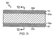
図5は、図1に示したものに類似した二層構成のEAP活性領域10が管状基材24a,24bの壁内に埋設されている他の実施形態の部分長手方向断面図である。前記管状基材24a,24bの双方とも非活性ポリマーマトリックス材料から形成されており、管状アセンブリ50を形成する。管状基材24a,24bは同一のポリマー材料から形成されてもよいし、またはそれぞれ異なるポリマー材料から形成されてもよい。
FIG. 4 is a partial longitudinal cross-sectional view of an EAP
FIG. 5 is a partial longitudinal cross-sectional view of another embodiment in which a two-layer EAP
図6は、図5の参照番号6−6において得られる半径方向断面図である。
これらの管状アセンブリは当業において既知の任意の方法を用いて形成され得る。実例として、フルオロポリマー、例えば、ポリテトラフルオロエチレン(PTFE)のような、当業では時として平滑面と称される低摩擦係数を有する材料から形成される管状基材2
4aは、当業において既知の任意の適当な技術を用いて、金の層で被覆され得る。適当な方法の例としては、EAPアクチュエータの導電層14を形成する、PTFEチューブ上へのスパッタコーティング、無電解メッキ、蒸着、電気めっきなどが挙げられるが、これらに限定されるものではない。上記処理のうちのいくつかには、当業において知られているように、PTFEの前処理が必要な場合がある。
FIG. 6 is a radial cross-sectional view taken at 6-6 in FIG.
These tubular assemblies can be formed using any method known in the art. Illustratively, a
4a can be coated with a gold layer using any suitable technique known in the art. Examples of suitable methods include, but are not limited to, sputter coating, electroless plating, vapor deposition, electroplating, etc. on the PTFE tube that forms the
別の特定の例においては、デラウェア州ウィルミントンのデュポン ド ヌムール アンド カンパニーから入手可能なKAPTON(登録商標)HN−100のような被覆ポリイミドが、「Effects of monomer and electrolyte concentrations on actuation of PPy (DBS) bilayers」の第19頁に記載されているように、導電性金属層によって被覆され、続いてPPyによって被覆され得る。 In another specific example, a coated polyimide, such as KAPTON® HN-100, available from DuPont de Nemours and Company of Wilmington, Delaware, “Effects of monomers and electrolysis of PPy (DBS It can be coated with a conductive metal layer, followed by PPy, as described on page 19 of bilayers.
ポリピロール(PPy)から形成された活性ポリマー層12を、上記で検討したような任意の適当な技術を用いて、例えば電解重合により、金層上に付着させ得る。図7に示すように、外側基材24bが空隙を有する場合には、外側管状部材は、押出技術のような当業において既知の任意の方法を用いて形成され得る。図7に示した実施形態の代わりとして、外側管状基材24bの内面は、液体電解質またはゲル電解質を保持するための貯蔵部を形成する凹部を有して構成され得る。EAP活性領域10に接触している電解質16を保持して示されている貯蔵部27を有して構成されている外側管状基材24bの内面25を備えた管状基材の半径方向の断面図。活性領域10は、活性ポリマー層12が貯蔵部内に保持された電解質16に接触するように、図9のように構成されて示されている。外側管状基材24bの内面25は、上記に記載したように、金また白金のような適切な導電性材料によって金属化され得る。
The
図10を参照すると、他の実施形態においては、ゲル電解質のような電解質の層16を付着させ、次に、熱収縮性材料の管状構造体24bをアセンブリ全体の周りに配置し、適切に熱で処理して収縮を引き起こすことによって、ゲル層を封入し得る。そのような熱収縮性チューブは、当業において公知であり、ポリオレフィンまたはそのコポリマーのような任意の適当な材料から形成され得る。図9はまた、活性ポリマー層12および導電層14を示す活性領域10の構成の実例である。熱収縮性外側管状基材24bをアセンブリ上に収縮させる前に、対向電極のために、金または白金のような適切な導電性ワイヤーをアセンブリの周りに巻き付けることができる。更に、作用電極として機能し得る導電基材層14はまた電圧源と接触しており、導電基材層14については、上記で既に検討した。イオンが電解質16と活性ポリマー層12との間で流動するのを可能にするために電位差が形成されることを条件として、任意の適当な電極/対向電極構成が用いられ得る。エネルギーの散逸が管状アセンブリにわたって最小限にされるように、前記ワイヤーはアセンブリの全長にわたって延在することが望ましい場合がある。
Referring to FIG. 10, in another embodiment, an
これに代わって、活性ポリマー層12上におけるゲル電解質層16の保持を改善するために、電解質を相互侵入高分子網目(IPN)内、または繊維網目内に捕捉してもよい。
ゲルを相互侵入高分子網目(IPN)内に捕捉する方法は、本発明の譲受人に譲渡された米国特許第5693034号、同第6265016号、同第6120904号、同第6080488号、同第6040058号、同第6030656号、同第6017577号、同第5919570号、同第5849368号、同第5662960号、同第5576072号に開示されている。上記各特許文献は、引用により、余すところなく本願に援用される。
Alternatively, the electrolyte may be trapped within an interpenetrating polymer network (IPN) or within a fiber network to improve retention of the
Methods for trapping gels within interpenetrating polymer networks (IPNs) are described in US Pat. No. 60306656, No. 6017577, No. 5919570, No. 5849368, No. 5662960, No. 5576072. Each of the above patent documents is incorporated herein by reference in its entirety.
当業において既知の任意の適当な技術を用いて、活性ポリマー層12に繊維を適用してもよい。繊維を適用する特定方法は電界紡糸である。フルノ、オードリー(Frenot
, Audrey)ら、「Polymer nanofibers assembled
by electrospinning」、Current Opinion in Colloid and Interface Science、8(2003年)、第64〜75頁を参照されたい。前記文献は、引用によって本願に援用される。
The fibers may be applied to the
, Audrey) et al., “Polymer nanofibers assembled.
by electrospinning ", Current Opinion in Colloid and Interface Science, 8 (2003), pp. 64-75. Said document is incorporated herein by reference.
各場合において、得たれたアセンブリを電解質中に浸漬し、管の周囲に金のワイヤーを巻き付け、次いで、上記に記載したような収縮被覆チューブ(shrink wrap tube)をアセンブリ全体の周囲に熱収縮させ得る。 In each case, the resulting assembly is immersed in an electrolyte, wrapped with a gold wire around the tube, and then a shrink wrap tube as described above is heat shrunk around the entire assembly. obtain.
一部の実施形態については、ゲルではなく、液体電解質を用いてもよい。例えば、電解質を適用する浸漬法が用いられる繊維網目の場合には、液体の電解質も用いられ得る。
電解質は、同様に、図7の部分斜視図に示すように基板層24b内に空隙26を形成するといったような様々な他の方法で、EAPアクチュエータ10の活性ポリマー層12に対して利用可能にされ得る。用いられるEAP活性領域10の構成は、図1に示した構成とほぼ同一であり得るので、アセンブリ全体が電解質溶液に露出される場合、例えば、電解質溶液からのイオンは、作動によって、活性ポリマー層12へ自由に流れる。もちろん、作動には、上述したように電極/対向電極によって電位差が形成されることが必要である。
For some embodiments, a liquid electrolyte may be used instead of a gel. For example, in the case of a fiber network using an immersion method in which an electrolyte is applied, a liquid electrolyte can also be used.
The electrolyte can also be utilized for the
これに代わって、電解質は、管状基材24aの内面25によって画定される管状基材の管腔30(図示せず)内に、例えば、ゲル電解質のような形態で、配置されてもよい。この実施形態において、望ましくは、管状基材24aには空隙が形成されており、活性領域10は、活性ポリマー層12がゲル電解質に露出されるように、図1に示すような反対の構成をとるであろう。これに代わって、例えば、拡張可能なバルーン部材の場合には、バルーン部材を拡張するために用いられる膨張媒体が電解質を含んでいてもよい。
Alternatively, the electrolyte may be placed in a tubular substrate lumen 30 (not shown) defined by the
さらに別の他の実施形態において、構造は図5に示す構造とほぼ同一であるが、管状基材32a,32bが固体高分子電解質を用いて形成されており、その管状基材32a,32bは管状アセンブリ60を形成する図1に示した活性領域10の一部である活性ポリマー層12の作動に実際に関与する。図8はこの実施形態の部分長手方向断面の描写であり、図9は図8の参照番号9−9で得られる半径方向断面図である。これに代わって、固体高分子電解質が図1に示すように活性ポリマー層12に接触している部材を形成する限り、管状基材32a,32bのうちの一方が非活性ポリマーマトリックス材料から形成されていてもよい。
In yet another embodiment, the structure is substantially the same as the structure shown in FIG. 5, but the
EAPアクチュエータが、機能するための基本的な要素、すなわち導電層、活性ポリマー層、電解質、適当な電極/対向電極の組み合わせを備えるならば、様々な構成を本願に用いてもよい。 Various configurations may be used in this application provided that the EAP actuator comprises the basic elements to function: conductive layer, active polymer layer, electrolyte, and appropriate electrode / counter electrode combination.
本願に記載するEAPアクチュエータは、様々な医療装置のいずれにおいても用いることができる。例えば、本願に記載するEAPアクチュエータは、チップ、内側シャフト、外側シャフト、後退可能なシース、拡張可能なバルーン部材などを含むが、これらに限定されるものではないカテーテルアセンブリおよびその構成要素の少なくとも一部において用いられ得る。 The EAP actuator described herein can be used in any of a variety of medical devices. For example, the EAP actuator described herein includes at least one of a catheter assembly and components thereof, including but not limited to a tip, an inner shaft, an outer shaft, a retractable sheath, an expandable balloon member, and the like. Can be used in parts.
一部の実施形態において、電気活性ポリマーは、カテーテルアセンブリの内側シャフト、外側シャフトまたはシースを形成するポリマーマトリックスの少なくとも一部内に埋設される。 In some embodiments, the electroactive polymer is embedded within at least a portion of the polymer matrix that forms the inner shaft, outer shaft, or sheath of the catheter assembly.
1つの特定の実施形態において、電気活性ポリマーは、外側カテーテルシャフトの先端
の少なくとも一部内に埋設され、前記シャフトは、非活性ポリマーまたは固体高分子電解質のいずれかから形成されている。EAPを作動させると、外側カテーテルシャフトの直径が拡張することにより、シャフトを血管壁に係留して、ステントのような医療装置が留置される間に、カテーテル装置の位置を維持する。
In one particular embodiment, the electroactive polymer is embedded within at least a portion of the distal end of the outer catheter shaft, the shaft being formed from either an inactive polymer or a solid polyelectrolyte. When the EAP is activated, the diameter of the outer catheter shaft expands to anchor the shaft to the vessel wall and maintain the position of the catheter device while a medical device such as a stent is deployed.
外側カテーテルシャフトはまた、マトリックス内にEAPを備える2つ以上の区域を有してもよい。作動時に、2つのEAP区域が体内管腔の一部を遮断することによって、標的領域に対する治療薬のより正確な目標とされた放出を可能にするように、外側シャフトの第1直径は第2直径よりも小さい。 The outer catheter shaft may also have more than one section with EAP in the matrix. In operation, the first diameter of the outer shaft is the second diameter so that the two EAP sections block a portion of the body lumen, thereby allowing more precise targeted release of the therapeutic agent to the target area. Smaller than the diameter.
また、体内管腔の大きさを増大させるために、カテーテルシャフト内に位置する複数のEAPの拡張可能区域を用いてもよい。
電気活性ポリマー系は、バルーンが取り付けられている先端内側カテーテルシャフトのマトリックス材料内に螺旋パターンで埋設されて、ねじれ作用(twisting function)を有する内側カテーテルシャフトを提供し、カテーテルバルーンの折り畳み/再巻き付けを向上する。EAPを用い得るそのようなねじれ機構の一例は、2005年11月14日出願の米国特許出願第11/272,886号に記載されている。前記特許文献の全容は、引用により本願に援用される。
A plurality of EAP expandable areas located within the catheter shaft may also be used to increase the size of the body lumen.
The electroactive polymer system is embedded in a spiral pattern within the matrix material of the distal inner catheter shaft to which the balloon is attached to provide an inner catheter shaft with twisting function, and folding / rewinding the catheter balloon To improve. An example of such a twisting mechanism that may use EAP is described in US patent application Ser. No. 11 / 272,886, filed Nov. 14, 2005. The entire contents of the above patent documents are incorporated herein by reference.
このような用途の他の例は、本発明の譲受人に譲渡された同時係属中の米国特許出願代理人整理番号S63.2−11954US01号に開示されている。
少なくとも一実施形態において、後退可能なシースは、マトリックス材料から形成されており、前記マトリックス材料の少なくとも一部は内部に埋設された電気活性ポリマーを有する。EAPを作動させると、シースは半径方向に拡張することによって、直径を増大し、シースをステントの上から後退させるときの展開力を低減するために、先端シースと搭載されたステントとの間の摩擦を低減する。また、EAPアクチュエータは、例えば、管状形または螺旋状を含む様々な形態で、シース内に埋設され得る。
Another example of such an application is disclosed in co-pending US Patent Application Attorney Docket No. S63.2-119554 US01, assigned to the assignee of the present invention.
In at least one embodiment, the retractable sheath is formed from a matrix material, and at least a portion of the matrix material has an electroactive polymer embedded therein. When the EAP is activated, the sheath expands radially to increase the diameter and reduce the deployment force when retracting the sheath over the stent to reduce the deployment force between the distal sheath and the mounted stent. Reduce friction. Also, the EAP actuator can be embedded in the sheath in various forms including, for example, a tubular shape or a spiral shape.
別の実施形態において、EAPアクチュエータは、先端シースの基端部内に埋設されて、先端シースの長手方向の伸張(作動(actuation))/短縮(作動停止(deactuation))を可能にする。 In another embodiment, the EAP actuator is embedded within the proximal end of the distal sheath to allow longitudinal extension (actuation) / shortening (deactuation) of the distal sheath.
一部の実施形態において、既存のカテーテル構成は、本願に記載したように、EAPをマトリックスの形で備えることによって変更され得る。そのような構成の一部の例は、本発明の譲受人に譲渡された同時係属中の米国特許出願代理人整理番号第S63.2−11948US01号、同第S63.2−11951US01号および同第S63.2−11952US01号に記載されている。前記各特許文献は、引用により、余すところなく本願に援用される。 In some embodiments, existing catheter configurations can be modified by providing EAP in the form of a matrix, as described herein. Some examples of such configurations include co-pending U.S. Patent Application Attorney Docket Nos. S63.2-11948US01, S63.2-11951US01 and the like assigned to the assignee of the present invention. S63.2-11952 US01. Each of the above patent documents is incorporated herein by reference in its entirety.
別の態様において、本発明はマトリックス材料から形成された拡張可能な医療用バルーンに関し、そのマトリックス材料の少なくとも一部内には、電気活性ポリマーアクチュエータが埋設されている。EAPアクチュエータは、本体部、くびれ部、および/または円錐部およびそれらの任意の組み合わせの中に埋設され得る。 In another aspect, the present invention relates to an expandable medical balloon formed from a matrix material with an electroactive polymer actuator embedded within at least a portion of the matrix material. The EAP actuator may be embedded in the body portion, constriction portion, and / or cone portion and any combination thereof.
電気活性ポリマー系は、折り畳みおよび再巻き付けを容易にし、改善された拡張および/または収縮制御を提供するように、マトリックス材料内に埋設され得る。一部の実施形態において、EAPは、本体部、円錐部および/またはくびれ部内に埋設されて、バルーンの折り畳みおよび再巻き付けを容易にする。例えば、バルーン壁内にバルーンの周について半径方向に均等に離間されて埋設されたEAPアクチュエータの細片は、該EAP細片の作動停止により、バルーンが潰れるのを支援し得る。 The electroactive polymer system can be embedded within the matrix material to facilitate folding and rewinding and to provide improved expansion and / or contraction control. In some embodiments, the EAP is embedded within the body, cone, and / or constriction to facilitate balloon folding and rewinding. For example, strips of EAP actuators embedded in the balloon wall that are evenly spaced radially about the circumference of the balloon may assist in collapsing the balloon by deactivating the EAP strip.
バルーンが形成されるポリマーマトリックス材料内にアクチュエータを埋設する方法の以下の例は、例示を目的としているに過ぎず、本発明の範囲を限定するものではない。
バルーンは当業において既知の任意の適当な方法を用いて形成することができる。一般に、その工程は、1)バルーンプリフォームを押し出す工程と、2)バルーンプリフォームをバルーン型内へ半径方向に拡張させる工程とを含む。もちろん、該プロセスには、同様に他の工程が含まれていてもよい。バルーン形成の方法の説明は、米国特許第4,490,421号において見られる。前記文献の全開示は、引用により、本願に援用される。
The following example of a method for embedding an actuator within the polymer matrix material from which the balloon is formed is for illustrative purposes only and is not intended to limit the scope of the invention.
The balloon can be formed using any suitable method known in the art. In general, the process includes 1) extruding the balloon preform and 2) radially expanding the balloon preform into the balloon mold. Of course, the process may include other steps as well. A description of the method of balloon formation can be found in US Pat. No. 4,490,421. The entire disclosure of said document is incorporated herein by reference.
バルーンが形成されたならば、層、すなわち、例えば金、白金などを、バルーン上にスパッタコーティングするなどの上記に記載したような任意の適当な方法を用いて、バルーンまたはバルーンの一部に導電層を施すことができる。次に、例えば電着などの上記に記載したような任意の適当な方法を用いて、導電層上に活性ポリマー層を付着させることができる。次に、前記層を埋設するために、任意の適当な技術を用いて、活性ポリマー層を包囲するように、活性ポリマー層上に別のポリマー層を施し得る。 Once the balloon has been formed, the layer, i.e., gold, platinum, etc., is electrically conductive on the balloon or part of the balloon using any suitable method as described above, such as sputter coating on the balloon. Layers can be applied. The active polymer layer can then be deposited on the conductive layer using any suitable method as described above, eg, electrodeposition. Next, to embed the layer, another suitable polymer layer can be applied over the active polymer layer using any suitable technique to surround the active polymer layer.
これに代わって、バルーンプリフォームをバルーン型内へ半径方向に拡張させる前に、上記に記載したように導体材料の薄層を施し、その後、光重合(すなわちソフトリソグラフィー)によるなどの活性ポリマー層の追加を行うことができる。EAPアクチュエータの非常に薄い層が施されたならば、次に、プリフォームをバルーン型内に配置して、半径方向に拡張させることができる。 Alternatively, a thin layer of conductive material is applied as described above before the balloon preform is radially expanded into the balloon mold, followed by an active polymer layer such as by photopolymerization (ie, soft lithography). Can be added. Once a very thin layer of EAP actuator has been applied, the preform can then be placed in a balloon mold and expanded radially.
これに代わって、第1のバルーンの上に、第2のプリブローされたバルーンを、それらの二者の間にアクチュエータを包み込むように組み付けて、次に、第2のバルーン型へ最後の半径方向の拡張を行った後に、ヒートセットを行う。 Alternatively, a second pre-blown balloon is assembled on top of the first balloon so as to wrap the actuator between the two, and then the final radial mold into the second balloon mold. After expansion, heat set.
バルーンの一部のみの上に位置するEAP活性領域を得る他の方法は、バルーンまたはバルーンプリフォームを完全に被覆し、次いで、例えば、化学的アブレーションまたはレーザアブレーションによる、または切削機械加工(subtractive machining)によるなどの既知の技術によって、選択的に材料を除去することを含み得る。 Another way to obtain an EAP active region located on only a part of the balloon is to completely coat the balloon or balloon preform and then for example by chemical or laser ablation or by subtractive machining And selectively removing material by known techniques, such as
これに代わって、活性ポリマー層および導電層を既に備えたEAPアクチュエータの予備形成片を、例えば、接着接合、または炭酸ガスレーザーを用いるようなレーザー熱接合などによって、バルーンプリフォームに接合し、そのプリフォームをバルーン型内に配置し、次いでその型内で半径方向に拡張させることができる。これに他のポリマー層が後続することができる。 Alternatively, a preformed piece of EAP actuator already provided with an active polymer layer and a conductive layer is bonded to the balloon preform by, for example, adhesive bonding or laser thermal bonding such as using a carbon dioxide laser. The preform can be placed in a balloon mold and then expanded radially within the mold. This can be followed by other polymer layers.
これに代わって、第1の共押し出しチューブ、少なくとも1つの導電層を備えたアクチュエータ、およびそれらのチューブとアクチュエータとの間に位置する少なくとも1つの活性ポリマー層の上に、第2のポリマーチューブを同心的に配置し、次いで、その管状アセンブリをバルーン型内に配置して、その型の中で半径方向に拡張させることができる。第1および第2の共押し出しチューブは、同一または異なるポリマーマトリックス材料から製造され得る。例えば、内側チューブはPTFEであり得、外側チューブはポリオレフィンまたはそのコポリマー、ポリ(エーテル−ブロック−アミド)ブロックコポリマーのようなブロックコポリマー、またはポリアルキレンテレフタレート(すなわちPETまたはPBT)のようなポリエステルまたはコポリエステルであり得る。 Alternatively, a second polymer tube is placed over the first co-extruded tube, the actuator with at least one conductive layer, and at least one active polymer layer located between the tube and the actuator. Placed concentrically, the tubular assembly can then be placed in a balloon mold and radially expanded within the mold. The first and second co-extruded tubes can be made from the same or different polymer matrix materials. For example, the inner tube can be PTFE and the outer tube can be a polyolefin or copolymer thereof, a block copolymer such as a poly (ether-block-amide) block copolymer, or a polyester or copolymer such as a polyalkylene terephthalate (ie PET or PBT). It can be polyester.
これらのEAPアクチュエータの予備形成片はまた、当業において知られているように、共押し出し技術を用いて、バルーン壁内に埋設され得る。
上記で検討したように、ポリマーマトリックス材料は、非活性ポリマーマトリックス材
料、または活性ポリマーマトリックス材料、すなわち固体高分子電解質であり得る。非活性である場合、アクチュエータの活性ポリマー層の電解質に対する露出は、上記に開示したような方法を用いて行われ得る。
These preformed pieces of EAP actuators can also be embedded within the balloon wall using co-extrusion techniques, as is known in the art.
As discussed above, the polymer matrix material can be a non-active polymer matrix material, or an active polymer matrix material, ie a solid polyelectrolyte. When inactive, exposure of the active polymer layer of the actuator to the electrolyte can be performed using methods such as those disclosed above.
バルーン壁を形成するポリマー層内に埋設されたEAPアクチュエータの細片は、バルーンの折り畳みを支援するように、バルーン上に有利に配置することができる。
一部の実施形態において、バルーンは、2つ、3つ、4つ、5つ、あるいは6つ以上の翼を有して形成され得る。例えば、三翼バルーン構造に対しては、3つの長手方向のEAP活性領域をバルーンの周のまわりに均等に配置することによって、これらのEAP活性領域は、EAP活性領域の収縮/作動停止により、バルーンの折り畳みを支援し得る。
Strips of the EAP actuator embedded in the polymer layer forming the balloon wall can be advantageously placed on the balloon to assist in folding the balloon.
In some embodiments, the balloon can be formed with 2, 3, 4, 5, or 6 or more wings. For example, for a three-wing balloon structure, by arranging three longitudinal EAP active regions evenly around the circumference of the balloon, these EAP active regions are caused by contraction / deactivation of the EAP active region, Can assist in folding the balloon.
したがって、これらの実施形態においては、バルーンの翼は、バルーンの折り畳みおよび再巻き付けを容易にするために、その翼内に埋設されたEAPアクチュエータを備えることができる。これらの種の用途は、本発明の譲受人に譲渡された同時係属中の米国特許出願代理人整理番号第S63.2−11947US01号に開示されている。前記文献の全容は、引用により、本願に援用される。 Thus, in these embodiments, the balloon wing may include an EAP actuator embedded in the wing to facilitate balloon folding and rewinding. These types of applications are disclosed in co-pending US Patent Application Attorney Docket No. S63.2-11947 US01, assigned to the assignee of the present invention. The entire contents of the above documents are incorporated herein by reference.
別の実施形態において、カテーテルアセンブリは、シースの少なくとも一部に埋設されたEAPを有するポリマーマトリックス材料のシースを備える。前記シースは、体内管腔を介した病変部位への搬送中に、バルーンを折り畳まれた形態に保持するために、カテーテルバルーン上に備えられる。この保護シースは拡張可能なバルーンのすべて、または一部もしく複数の部分のみを被覆し得る。 In another embodiment, the catheter assembly comprises a sheath of polymer matrix material having EAP embedded in at least a portion of the sheath. The sheath is provided on the catheter balloon to hold the balloon in a folded configuration during delivery to the lesion site through the body lumen. This protective sheath may cover all or part or only parts of the expandable balloon.
本発明によるEAPアクチュエータは、例えば、抜去中にカテーテルチップのプロファイルを制御するため、または前記チップに屈曲機能を与えるために、カテーテルチップ内に埋設されてもよい。この種の用途は、本発明の譲受人に譲渡された同時係属中の米国特許出願代理人整理番号第S63.2−11949US01号に開示されている。前記特許文献の全容は、引用により、本願に援用される。 The EAP actuator according to the present invention may be embedded in the catheter tip, for example, to control the profile of the catheter tip during withdrawal or to give the tip a bending function. This type of use is disclosed in co-pending U.S. Patent Application Attorney Docket No. S63.2-11949 US01, assigned to the assignee of the present invention. The entire contents of the above patent documents are incorporated herein by reference.
本願において開示するEAPアクチュエータはまた、分岐血管内で用いられるカテーテルおよびその構成要素に有用である。例えば、EAPアクチュエータは、ステントまたはステントグラフトのような医療装置の分岐血管の部位への搬送用に用いられるカテーテルデリバリーシステム、例えば、内側シャフトおよび/または外側シャフトおよびバルーンなど、と組み合わせて用いられてもよい。例えば、分岐部カテーテルの先端領域内に埋設されたEAPを用いることができる。前記EAPは、作動されると、カテーテルを側枝分岐部と整合するように回転させる。 The EAP actuator disclosed in this application is also useful for catheters and components thereof used in branch vessels. For example, an EAP actuator may be used in combination with a catheter delivery system used for delivery to a branch vessel site of a medical device such as a stent or stent graft, such as an inner shaft and / or an outer shaft and a balloon. Good. For example, EAP embedded in the distal region of the bifurcation catheter can be used. When activated, the EAP rotates the catheter to align with the side branch bifurcation.
本発明の別の実施形態は側枝ガイドワイヤー管腔内に埋設されたEAPに関する。該EAPは、作動されると、側枝を拡張し、回転させ、捻転させて、整合させる。所望の整合特性を与えるために側枝ガイドワイヤハウジングがEAP材料のマトリックスを組み込むように変更され得るアセンブリのいくつかの例は、米国特許出願公開第2005−0149161−A1号、同第2004−0172121−A1号、同第2005−0182473 A1号に示され、説明されている。上記の各特許文献の全容は、引用によって本願に援用される。 Another embodiment of the invention relates to an EAP embedded in a side branch guidewire lumen. When activated, the EAP expands, rotates, twists and aligns the side branch. Some examples of assemblies in which the side branch guidewire housing can be modified to incorporate a matrix of EAP material to provide the desired alignment characteristics are disclosed in US Patent Application Publication Nos. 2005-0149161-A1, 2004-0172121-. A1 and 2005-0182473 A1 are described and explained. The entire contents of each of the above patent documents are incorporated herein by reference.
分岐部血管に関する本発明の別の実施形態は、作動されると、側枝と適切に整合するように、バルーンの正確な回転を可能にする、バルーンの壁内に埋設されたEAPに関する。 Another embodiment of the present invention for bifurcated vessels relates to EAPs embedded in the balloon walls that, when activated, allow for accurate rotation of the balloon to properly align with the side branch.
分岐血管に関わる用途の検討については、代理人整理番号第S63.2−11955U
S01号を参照されたい。前記文献の全容は、引用により、本願に援用される。
他の実施形態において、EAPは、作動により、屈曲するようにさせられ得る。伸張/収縮または拡張/収縮ではなく、屈曲は、設計によって達成され得る。例えば、1つの方法は、可撓性であるが、選択した特定のEAPよりは伸長しないポリマーマトリックス材料を用いることである。図13は、活性ポリマー層12と、電源20と通じている導電基材層14とから形成された二層EAP活性領域10の概略図である。更に、対向電極18が電源に接続されて示されている。電解質の供給源(図示せず)は、活性ポリマー層12と連通していなければならない。上述したような多数の方法のいずれを用いてもよい。作動時の屈曲形状(actuated bended configuration)は、印加される外部電圧を反転させると、反転され得る。
For examination of applications related to branch vessels, agent reference number S63.2-11955U
See S01. The entire contents of the above documents are incorporated herein by reference.
In other embodiments, the EAP can be caused to flex upon actuation. Rather than stretching / contraction or expansion / contraction, bending can be achieved by design. For example, one method is to use a polymer matrix material that is flexible but does not stretch more than the particular EAP selected. FIG. 13 is a schematic diagram of a two-layer EAP
一実施形態において、この屈曲現象は、改善された病変との交差を示すカテーテルアセンブリを形成するために用いることができる。一部の実例において、蛇行性血管内の病変においてはカテーテルをセンタリングすることが困難であるため、カテーテルアセンブリを病変に交差させることが困難である。 In one embodiment, this bending phenomenon can be used to form a catheter assembly that exhibits improved crossing with a lesion. In some instances, it is difficult to cross the catheter assembly with the lesion because it is difficult to center the catheter in a tortuous intravascular lesion.
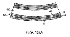
図15は、例えば使用の環境内、すなわち血管内におけるカテーテルアセンブリの側面斜視図である。この実施形態において、血管40は慢性完全閉塞(CTO)42を有して示されている。その血管内には、カテーテルシャフト44の先端に配置された拡張可能なバルーン部材46を備えたシャフト44を有するカテーテルが示されている。ガイドワイヤー48は、CTO42に押し通されて示されている。図15Aは、図15の断面15a−15aで得られた、分解断面図である。管腔45が示されている。これはガイドワイヤー管腔であってもよいし、または第2のカテーテルシャフト(図示せず)が配置され得る管腔であってもよい。当業において知られているように、カテーテルアセンブリは、内側シャフトおよび外側シャフトの双方を備えてもよく、内側シャフトおよび外側シャフトのいずれかまたは双方が、それらの壁の少なくとも一部の中にEAPアクチュエータを組み込み得る。カテーテルシャフトの先端側部分全体が、その内部に埋設されたEAP活性領域10を有してもよいし、または、カテーテルシャフトのある区域が、その内部に埋設されたEAP活性領域10を有してもよい。EAP活性領域10は、活性ポリマー層12および導電層14を有する二層構成として示されている。もちろん、作動のために、導電層10は電源(図示せず)と接触しており、また、上記で検討したように、必要な電位差を形成するために、対向電極(これも図示せず)が必要である。
FIG. 15 is a side perspective view of the catheter assembly, for example, within the environment of use, ie, within a blood vessel. In this embodiment, the
EAPの作動の前に、カテーテルをCTO42内に整合させることは困難である。
図16は、EAP活性領域10が作動された後における、図15に示したものに類似したカテーテルアセンブリの側面斜視図である。図16aは、カテーテル壁41内に埋設されたEAP活性領域10を示すために、図16のカテーテルシャフト44の断面16a−16aにおいて得られる。
Prior to EAP activation, it is difficult to align the catheter within the
FIG. 16 is a side perspective view of a catheter assembly similar to that shown in FIG. 15 after the EAP
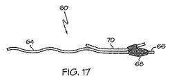
別の実施形態において、EAP活性領域は分岐したカテーテルアセンブリにおいて用いられる。前記分岐したカテーテルアセンブリ60は、斜視側面図として図17に示されている。前記カテーテルアセンブリ60は、先端部の周囲に配置された拡張可能なバルーン部材66と、拡張可能なバルーン部材66上に配置されて示されている分岐血管用ステント68とを有するシャフト64を備える。カテーテル60は、さらに第2ガイドワイヤー用の側枝ハウジング70を備えて示されている。これは例示のみを目的として用いられる簡素化したカテーテルアセンブリである。カテーテルアセンブリ60の配置に対する制御を高める目的のために、シャフト64(図17)がその少なくとも一部に埋設されたEAP活性領域を有してもよいし、または側枝ハウジング70(図18)がその内部に埋設されたEAP活性領域を有してもよい。図15aおよび図16aを参照されたい。
In another embodiment, the EAP active region is used in a bifurcated catheter assembly. The bifurcated catheter assembly 60 is shown in FIG. 17 as a perspective side view. The catheter assembly 60 includes a
また、当業において公知であるようなカテーテルアセンブリは、一般に、上記では示していない内側シャフトおよび外側シャフトを用いる。内側シャフトおよび/または外側シャフトのいずれも、内側シャフトおよび/または外側シャフトの壁の一部またはすべてにEAP活性領域を組み込み得る。 Also, catheter assemblies such as are known in the art typically use an inner shaft and an outer shaft not shown above. Either the inner shaft and / or the outer shaft may incorporate an EAP active region in some or all of the walls of the inner shaft and / or outer shaft.
Claims (25)
Applications Claiming Priority (2)
| Application Number | Priority Date | Filing Date | Title |
|---|---|---|---|
| US11/411,277 US7951186B2 (en) | 2006-04-25 | 2006-04-25 | Embedded electroactive polymer structures for use in medical devices |
| PCT/US2007/005195 WO2007126520A2 (en) | 2006-04-25 | 2007-02-28 | Embedded electroactive polymer structures for use in medical devices |
Publications (2)
| Publication Number | Publication Date |
|---|---|
| JP2009535093A true JP2009535093A (en) | 2009-10-01 |
| JP2009535093A5 JP2009535093A5 (en) | 2010-04-08 |
Family
ID=38445693
Family Applications (1)
| Application Number | Title | Priority Date | Filing Date |
|---|---|---|---|
| JP2009507679A Pending JP2009535093A (en) | 2006-04-25 | 2007-02-28 | Embedded electroactive polymer structure for use in medical devices |
Country Status (5)
| Country | Link |
|---|---|
| US (1) | US7951186B2 (en) |
| EP (1) | EP2012846A2 (en) |
| JP (1) | JP2009535093A (en) |
| CA (1) | CA2648098A1 (en) |
| WO (1) | WO2007126520A2 (en) |
Cited By (5)
| Publication number | Priority date | Publication date | Assignee | Title |
|---|---|---|---|---|
| WO2010100907A1 (en) * | 2009-03-04 | 2010-09-10 | パナソニック株式会社 | Polymer actuator |
| WO2011118391A1 (en) * | 2010-03-24 | 2011-09-29 | アルプス電気株式会社 | Polymer actuator and method for producing same |
| US8294329B2 (en) | 2009-12-24 | 2012-10-23 | Canon Kabushiki Kaisha | Polymer actuator |
| JP2019527469A (en) * | 2016-07-05 | 2019-09-26 | コーニンクレッカ フィリップス エヌ ヴェKoninklijke Philips N.V. | Shape deformation device |
| US10603191B2 (en) | 2014-11-04 | 2020-03-31 | Ras Labs, Inc. | Electroactive polymers and systems using the same |
Families Citing this family (84)
| Publication number | Priority date | Publication date | Assignee | Title |
|---|---|---|---|---|
| US8133249B2 (en) * | 2005-07-28 | 2012-03-13 | Ethicon Endo-Surgery, Inc. | Devices and methods for stricture dilation |
| US20070027519A1 (en) * | 2005-07-28 | 2007-02-01 | Ethicon Endo-Surgery, Inc. | Devices and methods for stent deployment |
| WO2007148572A1 (en) * | 2006-06-20 | 2007-12-27 | Panasonic Corporation | Polymer actuator |
| US8694076B2 (en) | 2006-07-06 | 2014-04-08 | Boston Scientific Scimed, Inc. | Electroactive polymer radiopaque marker |
| US7777399B2 (en) * | 2006-07-31 | 2010-08-17 | Boston Scientific Scimed, Inc. | Medical balloon incorporating electroactive polymer and methods of making and using the same |
| US9867530B2 (en) | 2006-08-14 | 2018-01-16 | Volcano Corporation | Telescopic side port catheter device with imaging system and method for accessing side branch occlusions |
| US8153181B2 (en) * | 2006-11-14 | 2012-04-10 | Boston Scientific Scimed, Inc. | Medical devices and related methods |
| US7982375B2 (en) * | 2006-12-13 | 2011-07-19 | Board Of Trustees Of Michigan State University | Integrated actuator sensor structure |
| WO2009009802A1 (en) | 2007-07-12 | 2009-01-15 | Volcano Corporation | Oct-ivus catheter for concurrent luminal imaging |
| WO2009009799A1 (en) | 2007-07-12 | 2009-01-15 | Volcano Corporation | Catheter for in vivo imaging |
| US9596993B2 (en) | 2007-07-12 | 2017-03-21 | Volcano Corporation | Automatic calibration systems and methods of use |
| US20090157048A1 (en) * | 2007-12-18 | 2009-06-18 | Boston Scientific Scimed, Inc. | Spiral cut hypotube |
| US8298158B2 (en) * | 2009-06-30 | 2012-10-30 | Abbott Diabetes Care Inc. | Integrated devices having extruded electrode structures and methods of using same |
| DE102009036424A1 (en) * | 2009-08-06 | 2011-02-10 | Richard Wolf Gmbh | Endoscopic instrument |
| TWI398801B (en) * | 2009-08-21 | 2013-06-11 | J Touch Corp | Transparent vibrating elements and their modules |
| US8683798B2 (en) * | 2010-01-15 | 2014-04-01 | Syracuse University | Stimuli-responsive product |
| US9227041B2 (en) * | 2010-04-09 | 2016-01-05 | Boston Scientific Scimed, Inc. | Balloon catheters with fibers for delivery of therapeutic agent and methods of making the same |
| EP2560722A2 (en) | 2010-04-21 | 2013-02-27 | The Regents of the University of Michigan | Fluoroscopy-independent, endovascular aortic occlusion system |
| CN101840991B (en) * | 2010-04-30 | 2012-01-25 | 清华大学 | Electrical actuating structure and electrical actuating element |
| CN103327935B (en) * | 2010-12-14 | 2016-10-19 | 杭州启明医疗器械有限公司 | Including the alignment device of device, set group and method |
| US11141063B2 (en) | 2010-12-23 | 2021-10-12 | Philips Image Guided Therapy Corporation | Integrated system architectures and methods of use |
| US11040140B2 (en) | 2010-12-31 | 2021-06-22 | Philips Image Guided Therapy Corporation | Deep vein thrombosis therapeutic methods |
| WO2013003757A2 (en) | 2011-06-30 | 2013-01-03 | The Spectranetics Corporation | Reentry catheter and method thereof |
| US8956376B2 (en) | 2011-06-30 | 2015-02-17 | The Spectranetics Corporation | Reentry catheter and method thereof |
| US8998936B2 (en) | 2011-06-30 | 2015-04-07 | The Spectranetics Corporation | Reentry catheter and method thereof |
| US9360630B2 (en) | 2011-08-31 | 2016-06-07 | Volcano Corporation | Optical-electrical rotary joint and methods of use |
| JP5930534B2 (en) * | 2012-06-08 | 2016-06-08 | アルプス電気株式会社 | Polymer actuator device system |
| US10568586B2 (en) | 2012-10-05 | 2020-02-25 | Volcano Corporation | Systems for indicating parameters in an imaging data set and methods of use |
| US9307926B2 (en) | 2012-10-05 | 2016-04-12 | Volcano Corporation | Automatic stent detection |
| US9324141B2 (en) | 2012-10-05 | 2016-04-26 | Volcano Corporation | Removal of A-scan streaking artifact |
| US11272845B2 (en) | 2012-10-05 | 2022-03-15 | Philips Image Guided Therapy Corporation | System and method for instant and automatic border detection |
| US9286673B2 (en) | 2012-10-05 | 2016-03-15 | Volcano Corporation | Systems for correcting distortions in a medical image and methods of use thereof |
| US9292918B2 (en) | 2012-10-05 | 2016-03-22 | Volcano Corporation | Methods and systems for transforming luminal images |
| US9858668B2 (en) | 2012-10-05 | 2018-01-02 | Volcano Corporation | Guidewire artifact removal in images |
| US9367965B2 (en) | 2012-10-05 | 2016-06-14 | Volcano Corporation | Systems and methods for generating images of tissue |
| US10070827B2 (en) | 2012-10-05 | 2018-09-11 | Volcano Corporation | Automatic image playback |
| JP2015532536A (en) | 2012-10-05 | 2015-11-09 | デイビッド ウェルフォード, | System and method for amplifying light |
| US9840734B2 (en) | 2012-10-22 | 2017-12-12 | Raindance Technologies, Inc. | Methods for analyzing DNA |
| EP2931132B1 (en) | 2012-12-13 | 2023-07-05 | Philips Image Guided Therapy Corporation | System for targeted cannulation |
| WO2014099899A1 (en) | 2012-12-20 | 2014-06-26 | Jeremy Stigall | Smooth transition catheters |
| US10939826B2 (en) | 2012-12-20 | 2021-03-09 | Philips Image Guided Therapy Corporation | Aspirating and removing biological material |
| US10942022B2 (en) | 2012-12-20 | 2021-03-09 | Philips Image Guided Therapy Corporation | Manual calibration of imaging system |
| EP2934310A4 (en) | 2012-12-20 | 2016-10-12 | Nathaniel J Kemp | Optical coherence tomography system that is reconfigurable between different imaging modes |
| CA2895770A1 (en) | 2012-12-20 | 2014-07-24 | Jeremy Stigall | Locating intravascular images |
| US11406498B2 (en) | 2012-12-20 | 2022-08-09 | Philips Image Guided Therapy Corporation | Implant delivery system and implants |
| EP2934323A4 (en) | 2012-12-21 | 2016-08-17 | Andrew Hancock | System and method for multipath processing of image signals |
| CA2896006A1 (en) | 2012-12-21 | 2014-06-26 | David Welford | Systems and methods for narrowing a wavelength emission of light |
| WO2014100402A1 (en) * | 2012-12-21 | 2014-06-26 | Howard Alpert | System and method for guidewire control |
| EP2934280B1 (en) | 2012-12-21 | 2022-10-19 | Mai, Jerome | Ultrasound imaging with variable line density |
| US9486143B2 (en) | 2012-12-21 | 2016-11-08 | Volcano Corporation | Intravascular forward imaging device |
| US10413317B2 (en) | 2012-12-21 | 2019-09-17 | Volcano Corporation | System and method for catheter steering and operation |
| WO2014100606A1 (en) | 2012-12-21 | 2014-06-26 | Meyer, Douglas | Rotational ultrasound imaging catheter with extended catheter body telescope |
| WO2014100162A1 (en) | 2012-12-21 | 2014-06-26 | Kemp Nathaniel J | Power-efficient optical buffering using optical switch |
| US9612105B2 (en) | 2012-12-21 | 2017-04-04 | Volcano Corporation | Polarization sensitive optical coherence tomography system |
| EP2936426B1 (en) | 2012-12-21 | 2021-10-13 | Jason Spencer | System and method for graphical processing of medical data |
| US10058284B2 (en) | 2012-12-21 | 2018-08-28 | Volcano Corporation | Simultaneous imaging, monitoring, and therapy |
| US9474882B2 (en) | 2013-02-26 | 2016-10-25 | Prytime Medical Devices, Inc. | Fluoroscopy-independent balloon guided occlusion catheter and methods |
| US9770172B2 (en) | 2013-03-07 | 2017-09-26 | Volcano Corporation | Multimodal segmentation in intravascular images |
| US10226597B2 (en) | 2013-03-07 | 2019-03-12 | Volcano Corporation | Guidewire with centering mechanism |
| EP2967391A4 (en) | 2013-03-12 | 2016-11-02 | Donna Collins | Systems and methods for diagnosing coronary microvascular disease |
| US11154313B2 (en) | 2013-03-12 | 2021-10-26 | The Volcano Corporation | Vibrating guidewire torquer and methods of use |
| US10758207B2 (en) | 2013-03-13 | 2020-09-01 | Philips Image Guided Therapy Corporation | Systems and methods for producing an image from a rotational intravascular ultrasound device |
| US11026591B2 (en) | 2013-03-13 | 2021-06-08 | Philips Image Guided Therapy Corporation | Intravascular pressure sensor calibration |
| US9301687B2 (en) | 2013-03-13 | 2016-04-05 | Volcano Corporation | System and method for OCT depth calibration |
| US10292677B2 (en) | 2013-03-14 | 2019-05-21 | Volcano Corporation | Endoluminal filter having enhanced echogenic properties |
| US20160030151A1 (en) | 2013-03-14 | 2016-02-04 | Volcano Corporation | Filters with echogenic characteristics |
| US10219887B2 (en) | 2013-03-14 | 2019-03-05 | Volcano Corporation | Filters with echogenic characteristics |
| US10302586B2 (en) * | 2013-04-10 | 2019-05-28 | President And Fellows Of Harvard College | Stretchable ionics for transparent sensors and actuators |
| JP6343009B2 (en) | 2013-09-09 | 2018-06-13 | プリタイム・メディカル・デバイシーズ・インコーポレイテッドPrytime Medical Devices,Inc. | Low profile occlusion catheter |
| US10188512B2 (en) | 2013-12-30 | 2019-01-29 | George O. Angheloiu | Reversible cavitary tension membrane |
| FR3019993B1 (en) * | 2014-04-16 | 2019-07-19 | Institut National Des Sciences Appliquees De Lyon | CONTROLLED VARIABLE FLEXIBILITY GUIDE WIRE |
| US10232142B2 (en) | 2014-06-10 | 2019-03-19 | Prytime Medical Devices, Inc. | Conduit guiding tip |
| JP6472536B2 (en) | 2015-03-19 | 2019-02-20 | プリタイム・メディカル・デバイシーズ・インコーポレイテッドPrytime Medical Devices,Inc. | System and method for low profile occlusion balloon catheter |
| US10603195B1 (en) | 2015-05-20 | 2020-03-31 | Paul Sherburne | Radial expansion and contraction features of medical devices |
| BR112018003586A2 (en) | 2015-08-31 | 2018-09-25 | Koninklijke Philips Nv | actuator and / or sensor device |
| AU2017214568B9 (en) | 2016-02-05 | 2020-07-09 | Board Of Regents Of The University Of Texas System | Steerable intra-luminal medical device |
| EP3463106B1 (en) | 2016-06-02 | 2023-10-25 | Prytime Medical Devices, Inc. | System for low profile occlusion balloon catheter |
| EP3469630B1 (en) * | 2016-06-14 | 2020-01-22 | Koninklijke Philips N.V. | Electroactive polymer actuator device and driving method |
| US11289700B2 (en) | 2016-06-28 | 2022-03-29 | The Research Foundation For The State University Of New York | KVOPO4 cathode for sodium ion batteries |
| US10456283B2 (en) | 2016-07-13 | 2019-10-29 | Boston Scientific Scimed, Inc. | Apparatus and method for maintaining patency in a vessel adjacent to nearby surgery |
| CN110446523B (en) | 2017-01-12 | 2022-06-10 | 加利福尼亚大学董事会 | Intravascular perfusion enhancement for critical care |
| EP3612086A4 (en) | 2017-04-21 | 2021-01-20 | The Regents of the University of California, A California Corporation | Aortic flow meter and pump for partial-aortic occlusion |
| EP3802695B1 (en) * | 2018-06-05 | 2023-07-05 | Bioastra Technologies, Inc. | Stretchable solid-state electroactive polymer actuators |
| US20210322026A1 (en) | 2020-03-16 | 2021-10-21 | Certus Critical Care, Inc. | Blood flow control devices, systems, and methods and error detection thereof |
Citations (4)
| Publication number | Priority date | Publication date | Assignee | Title |
|---|---|---|---|---|
| JP2004216868A (en) * | 2002-11-05 | 2004-08-05 | Eamex Co | Method of producing electrically conductive polymer composite structure, laminate and electrically conductive polymer |
| JP2004350495A (en) * | 2003-04-25 | 2004-12-09 | Eamex Co | Bending driving device and micro device |
| WO2004112233A1 (en) * | 2003-06-17 | 2004-12-23 | Eamex Corporation | Polymer actuator |
| JP2007521871A (en) * | 2004-01-23 | 2007-08-09 | ボストン サイエンティフィック リミティッド | Electrically operated medical device |
Family Cites Families (42)
| Publication number | Priority date | Publication date | Assignee | Title |
|---|---|---|---|---|
| US4490421A (en) * | 1983-07-05 | 1984-12-25 | E. I. Du Pont De Nemours And Company | Balloon and manufacture thereof |
| CA1321164C (en) * | 1987-02-27 | 1993-08-10 | Robert N. O'brien | Bilayer electronically conductive polymers and process for their production |
| US4933052A (en) * | 1987-02-27 | 1990-06-12 | University Of Victoria | Process for the preparation of continuous bilayer electronically-conductive polymer films |
| US5147302A (en) * | 1989-04-21 | 1992-09-15 | Scimed Life Systems, Inc. | Method of shaping a balloon of a balloon catheter |
| CA2117088A1 (en) * | 1991-09-05 | 1993-03-18 | David R. Holmes | Flexible tubular device for use in medical applications |
| JPH06506019A (en) * | 1991-12-18 | 1994-07-07 | シメッド ライフ システムズ インコーポレイテッド | Lubricious polymer network |
| DE69418751T2 (en) * | 1993-03-19 | 1999-11-11 | Mitsubishi Chem Corp | Thermoplastic resin composition |
| MX9705922A (en) * | 1995-02-01 | 1997-10-31 | Schneider Usa Inc | Process for hydrophilicization of hydrophobic polymers. |
| US5919570A (en) * | 1995-02-01 | 1999-07-06 | Schneider Inc. | Slippery, tenaciously adhering hydrogel coatings containing a polyurethane-urea polymer hydrogel commingled with a poly(N-vinylpyrrolidone) polymer hydrogel, coated polymer and metal substrate materials, and coated medical devices |
| US5576072A (en) * | 1995-02-01 | 1996-11-19 | Schneider (Usa), Inc. | Process for producing slippery, tenaciously adhering hydrogel coatings containing a polyurethane-urea polymer hydrogel commingled with at least one other, dissimilar polymer hydrogel |
| US5662960A (en) * | 1995-02-01 | 1997-09-02 | Schneider (Usa) Inc. | Process for producing slippery, tenaciously adhering hydrogel coatings containing a polyurethane-urea polymer hydrogel commingled with a poly (n-vinylpyrrolidone) polymer hydrogel |
| US6017577A (en) * | 1995-02-01 | 2000-01-25 | Schneider (Usa) Inc. | Slippery, tenaciously adhering hydrophilic polyurethane hydrogel coatings, coated polymer substrate materials, and coated medical devices |
| US6781284B1 (en) * | 1997-02-07 | 2004-08-24 | Sri International | Electroactive polymer transducers and actuators |
| US6812624B1 (en) * | 1999-07-20 | 2004-11-02 | Sri International | Electroactive polymers |
| US5855565A (en) * | 1997-02-21 | 1999-01-05 | Bar-Cohen; Yaniv | Cardiovascular mechanically expanding catheter |
| BR9908339A (en) * | 1998-02-23 | 2001-10-02 | Mnemoscience Gmbh | Method for the manufacture of an article with format memory, polymer composition with format memory and respective method of forming the field |
| US6249076B1 (en) * | 1998-04-14 | 2001-06-19 | Massachusetts Institute Of Technology | Conducting polymer actuator |
| US6117296A (en) * | 1998-07-21 | 2000-09-12 | Thomson; Timothy | Electrically controlled contractile polymer composite |
| US6123718A (en) * | 1998-11-02 | 2000-09-26 | Polymerex Medical Corp. | Balloon catheter |
| US20050085693A1 (en) * | 2000-04-03 | 2005-04-21 | Amir Belson | Activated polymer articulated instruments and methods of insertion |
| US6982514B1 (en) * | 2000-05-22 | 2006-01-03 | Santa Fe Science And Technology, Inc. | Electrochemical devices incorporating high-conductivity conjugated polymers |
| US6803446B2 (en) | 2000-07-13 | 2004-10-12 | The Board Of Governors For Higher Education, State Of Rhode Island And Providence Plantations | Functionalized and processable conducting polymers |
| US6514237B1 (en) * | 2000-11-06 | 2003-02-04 | Cordis Corporation | Controllable intralumen medical device |
| JP3878839B2 (en) * | 2001-05-31 | 2007-02-07 | チ メイ オプトエレクトロニクス コーポレーション | Aluminum wiring layer without hillock and method for forming the same |
| AU2002354954A1 (en) * | 2001-07-20 | 2003-03-03 | The Research Foundation Of State University Of New York | Polymer-matrix materials and methods for making same |
| DE10138115A1 (en) * | 2001-08-03 | 2003-02-27 | Daimler Chrysler Ag | Automated, unsynchronized gear shift transmission and method for changing gears in such |
| US6770027B2 (en) * | 2001-10-05 | 2004-08-03 | Scimed Life Systems, Inc. | Robotic endoscope with wireless interface |
| US6835173B2 (en) * | 2001-10-05 | 2004-12-28 | Scimed Life Systems, Inc. | Robotic endoscope |
| WO2003049658A1 (en) | 2001-12-10 | 2003-06-19 | Hearworks Pty. Ltd. | Control of shape of an implantable electrode array |
| JP3832338B2 (en) * | 2001-12-25 | 2006-10-11 | 松下電工株式会社 | Electrostrictive polymer actuator |
| US6749556B2 (en) * | 2002-05-10 | 2004-06-15 | Scimed Life Systems, Inc. | Electroactive polymer based artificial sphincters and artificial muscle patches |
| US6679836B2 (en) * | 2002-06-21 | 2004-01-20 | Scimed Life Systems, Inc. | Universal programmable guide catheter |
| US7063671B2 (en) * | 2002-06-21 | 2006-06-20 | Boston Scientific Scimed, Inc. | Electronically activated capture device |
| US6969395B2 (en) * | 2002-08-07 | 2005-11-29 | Boston Scientific Scimed, Inc. | Electroactive polymer actuated medical devices |
| US20040068161A1 (en) * | 2002-10-02 | 2004-04-08 | Couvillon Lucien Alfred | Thrombolysis catheter |
| US7314480B2 (en) * | 2003-02-27 | 2008-01-01 | Boston Scientific Scimed, Inc. | Rotating balloon expandable sheath bifurcation delivery |
| US7338509B2 (en) * | 2003-11-06 | 2008-03-04 | Boston Scientific Scimed, Inc. | Electroactive polymer actuated sheath for implantable or insertable medical device |
| US7686841B2 (en) * | 2003-12-29 | 2010-03-30 | Boston Scientific Scimed, Inc. | Rotating balloon expandable sheath bifurcation delivery system |
| US8012192B2 (en) * | 2004-02-18 | 2011-09-06 | Boston Scientific Scimed, Inc. | Multi-stent delivery system |
| US7225518B2 (en) * | 2004-02-23 | 2007-06-05 | Boston Scientific Scimed, Inc. | Apparatus for crimping a stent assembly |
| US20070027519A1 (en) * | 2005-07-28 | 2007-02-01 | Ethicon Endo-Surgery, Inc. | Devices and methods for stent deployment |
| US8133249B2 (en) * | 2005-07-28 | 2012-03-13 | Ethicon Endo-Surgery, Inc. | Devices and methods for stricture dilation |
-
2006
- 2006-04-25 US US11/411,277 patent/US7951186B2/en not_active Expired - Fee Related
-
2007
- 2007-02-28 WO PCT/US2007/005195 patent/WO2007126520A2/en active Application Filing
- 2007-02-28 CA CA002648098A patent/CA2648098A1/en not_active Abandoned
- 2007-02-28 EP EP07751926A patent/EP2012846A2/en not_active Withdrawn
- 2007-02-28 JP JP2009507679A patent/JP2009535093A/en active Pending
Patent Citations (4)
| Publication number | Priority date | Publication date | Assignee | Title |
|---|---|---|---|---|
| JP2004216868A (en) * | 2002-11-05 | 2004-08-05 | Eamex Co | Method of producing electrically conductive polymer composite structure, laminate and electrically conductive polymer |
| JP2004350495A (en) * | 2003-04-25 | 2004-12-09 | Eamex Co | Bending driving device and micro device |
| WO2004112233A1 (en) * | 2003-06-17 | 2004-12-23 | Eamex Corporation | Polymer actuator |
| JP2007521871A (en) * | 2004-01-23 | 2007-08-09 | ボストン サイエンティフィック リミティッド | Electrically operated medical device |
Cited By (9)
| Publication number | Priority date | Publication date | Assignee | Title |
|---|---|---|---|---|
| WO2010100907A1 (en) * | 2009-03-04 | 2010-09-10 | パナソニック株式会社 | Polymer actuator |
| US8487505B2 (en) | 2009-03-04 | 2013-07-16 | Panasonic Corporation | Polymer actuator |
| US8294329B2 (en) | 2009-12-24 | 2012-10-23 | Canon Kabushiki Kaisha | Polymer actuator |
| WO2011118391A1 (en) * | 2010-03-24 | 2011-09-29 | アルプス電気株式会社 | Polymer actuator and method for producing same |
| JP5523553B2 (en) * | 2010-03-24 | 2014-06-18 | アルプス電気株式会社 | Polymer actuator and manufacturing method thereof |
| US10603191B2 (en) | 2014-11-04 | 2020-03-31 | Ras Labs, Inc. | Electroactive polymers and systems using the same |
| JP2019527469A (en) * | 2016-07-05 | 2019-09-26 | コーニンクレッカ フィリップス エヌ ヴェKoninklijke Philips N.V. | Shape deformation device |
| JP7036753B2 (en) | 2016-07-05 | 2022-03-15 | コーニンクレッカ フィリップス エヌ ヴェ | Shape deformer |
| JP7036753B6 (en) | 2016-07-05 | 2022-05-30 | コーニンクレッカ フィリップス エヌ ヴェ | Shape deformer |
Also Published As
| Publication number | Publication date |
|---|---|
| US7951186B2 (en) | 2011-05-31 |
| WO2007126520A2 (en) | 2007-11-08 |
| WO2007126520A3 (en) | 2008-08-21 |
| EP2012846A2 (en) | 2009-01-14 |
| US20070247033A1 (en) | 2007-10-25 |
| CA2648098A1 (en) | 2007-11-08 |
Similar Documents
| Publication | Publication Date | Title |
|---|---|---|
| US7951186B2 (en) | Embedded electroactive polymer structures for use in medical devices | |
| US7919910B2 (en) | Medical balloon incorporating electroactive polymer and methods of making and using the same | |
| JP5172838B2 (en) | Catheter with actuable lumen assembly | |
| JP2009528883A (en) | Adjustable catheter tip | |
| US7766896B2 (en) | Variable stiffness catheter assembly | |
| US8398693B2 (en) | Electrically actuated medical devices | |
| JP4699378B2 (en) | Electroactive polymer driven sheath for implantable or insertable medical devices | |
| US20080109061A1 (en) | Adjustable bifurcation catheter incorporating electroactive polymer and methods of making and using the same | |
| JP2009508627A (en) | Bifurcated stent | |
| US20070249909A1 (en) | Catheter configurations | |
| JP2016513542A (en) | Small blood vessel auxiliary guidewire |
Legal Events
| Date | Code | Title | Description |
|---|---|---|---|
| A521 | Written amendment |
Free format text: JAPANESE INTERMEDIATE CODE: A523 Effective date: 20100219 |
|
| A621 | Written request for application examination |
Free format text: JAPANESE INTERMEDIATE CODE: A621 Effective date: 20100219 |
|
| RD04 | Notification of resignation of power of attorney |
Free format text: JAPANESE INTERMEDIATE CODE: A7424 Effective date: 20120119 |
|
| A131 | Notification of reasons for refusal |
Free format text: JAPANESE INTERMEDIATE CODE: A131 Effective date: 20120904 |
|
| A601 | Written request for extension of time |
Free format text: JAPANESE INTERMEDIATE CODE: A601 Effective date: 20121204 |
|
| A602 | Written permission of extension of time |
Free format text: JAPANESE INTERMEDIATE CODE: A602 Effective date: 20121211 |
|
| A601 | Written request for extension of time |
Free format text: JAPANESE INTERMEDIATE CODE: A601 Effective date: 20130104 |
|
| A602 | Written permission of extension of time |
Free format text: JAPANESE INTERMEDIATE CODE: A602 Effective date: 20130111 |
|
| A521 | Written amendment |
Free format text: JAPANESE INTERMEDIATE CODE: A523 Effective date: 20130130 |
|
| A131 | Notification of reasons for refusal |
Free format text: JAPANESE INTERMEDIATE CODE: A131 Effective date: 20130430 |
|
| A02 | Decision of refusal |
Free format text: JAPANESE INTERMEDIATE CODE: A02 Effective date: 20131105 |