JP2009533772A - Technology that easily uses small line buffers to process small or large images - Google Patents
Technology that easily uses small line buffers to process small or large images Download PDFInfo
- Publication number
- JP2009533772A JP2009533772A JP2009505581A JP2009505581A JP2009533772A JP 2009533772 A JP2009533772 A JP 2009533772A JP 2009505581 A JP2009505581 A JP 2009505581A JP 2009505581 A JP2009505581 A JP 2009505581A JP 2009533772 A JP2009533772 A JP 2009533772A
- Authority
- JP
- Japan
- Prior art keywords
- image
- width
- line buffer
- vertical stripes
- viewfinder
- Prior art date
- Legal status (The legal status is an assumption and is not a legal conclusion. Google has not performed a legal analysis and makes no representation as to the accuracy of the status listed.)
- Withdrawn
Links
Images


Classifications
-
- G—PHYSICS
- G06—COMPUTING; CALCULATING OR COUNTING
- G06T—IMAGE DATA PROCESSING OR GENERATION, IN GENERAL
- G06T1/00—General purpose image data processing
- G06T1/60—Memory management
-
- G—PHYSICS
- G06—COMPUTING; CALCULATING OR COUNTING
- G06T—IMAGE DATA PROCESSING OR GENERATION, IN GENERAL
- G06T1/00—General purpose image data processing
Abstract
本開示は、異なる大きさの画像の画像処理をサポートするデバイスのために役立つ画像処理技術を説明する。この技術は多くの状況において用いられることができ、特に、デバイスによって取得された小さなビューファインダ画像及び大きな静止画像のフロントエンド画像処理のために役立つ。1つの実施形態において、本開示は、デバイスを用いて第1の画像を取得することと、第1の画像の画像幅を収納できる大きさのラインバッファを用いて第1の画像を処理することと、デバイスを用いて、第1の画像の画像幅よりも大きい画像幅を有する第2の画像を取得することとを備える方法を提供する。この方法は、ラインバッファを用いて、ラインバッファ内に収まる幅を定める前記第2の画像の縦縞を処理することも含む。This disclosure describes image processing techniques that are useful for devices that support image processing of images of different sizes. This technique can be used in many situations and is particularly useful for front-end image processing of small viewfinder images and large still images acquired by the device. In one embodiment, the present disclosure obtains a first image using a device and processes the first image using a line buffer sized to accommodate the image width of the first image. And using a device to obtain a second image having an image width greater than the image width of the first image. The method also includes using a line buffer to process the vertical stripes of the second image that define a width that fits within the line buffer.
Description
本発明は画像処理及びビデオ処理に関し、特に、異なる大きさの画像の効率的な処理のためのメモリ格納技術に関する。 The present invention relates to image processing and video processing, and more particularly to a memory storage technique for efficient processing of images of different sizes.
多くの「フロントエンド」画像処理技術は、しばしばイメージングデバイス内又はビデオデバイス内で行われる。一般にこのようなデバイスは、ビデオシーケンスからの例えば個々の静止画像又は画像シーケンスのような生画像データを得る画像センサを含む。画像品質を向上させるためにしばしば生データについて、画像処理技術が実行される。このような画像処理技術の例は、いくつかの例を挙げると、2次元フィルタリング、デモザイク、レンズロールオフ補正、拡大縮小、色補正、色変換、ノイズ低減フィルタリング、及び空間フィルタリングである。フロントエンド処理は、例えば階調再現、彩度、色彩再現及び鮮明さのようなビジュアル画像品質特性を向上させることができる。 Many “front-end” image processing techniques are often performed in an imaging device or a video device. Such devices typically include an image sensor that obtains raw image data such as individual still images or image sequences from a video sequence. Image processing techniques are often performed on raw data to improve image quality. Examples of such image processing techniques are two-dimensional filtering, demosaicing, lens roll-off correction, scaling, color correction, color conversion, noise reduction filtering, and spatial filtering, to name a few examples. Front-end processing can improve visual image quality characteristics such as tone reproduction, saturation, color reproduction and sharpness.
多くの場合において、デバイスは、いくつかの異なる大きさの異なる画像について、画像処理技術をサポートする必要がある。実際に、デバイスによってサポートされる必要がある画像の大きさは、いくつかの場合において抜本的に変化しうる。例えばデバイスは、デバイスのビューファインダにおいてリアルタイムで非常に小さな画像のシーケンスを表示し、ビューファインダにおける画像品質を向上させるために、このような画像に迅速に画像処理を行う必要がある。加えて、デバイスは、例えばデバイスによって取得された静止画像や、デバイスによって取得された画像のビデオシーケンスのような非常に大きな画像に、画像処理技術を行うことができる。異なる画像に対する画像処理をサポートするために、従来技術は、画像処理モジュール内のラインバッファに、デバイスによって処理可能である最も大きな画像の画像幅を収納できることを課した。ラインバッファは、画像データのライン又はラインの一部を格納するために用いられる、小さく、一時的な記憶場所である。ラインバッファは一般にオンチップであり、1つ又は複数の処理モジュールに関連する。 In many cases, devices need to support image processing techniques for several different sized images. In fact, the size of the image that needs to be supported by the device can vary drastically in some cases. For example, the device needs to rapidly image such images in order to display a very small sequence of images in real time in the device's viewfinder and improve the image quality in the viewfinder. In addition, the device can perform image processing techniques on very large images such as, for example, still images acquired by the device or video sequences of images acquired by the device. In order to support image processing for different images, the prior art has imposed that the line buffer in the image processing module can accommodate the image width of the largest image that can be processed by the device. A line buffer is a small, temporary storage location used to store lines or portions of lines of image data. Line buffers are generally on-chip and associated with one or more processing modules.
本開示は、異なる大きさの画像の画像処理をサポートするデバイスのために役立つ画像処理技術を説明する。この技術は、多数の文脈において用いられることができ、特に、デバイスによって取得される小さなビューファインダ画像及び大きな静止画像のフロントエンド画像処理のために役立つ。本明細書で説明される技術は、画像処理に関連するラインバッファの大きさの著しい低減を可能とする。本開示によると、ラインバッファは小さなビューファインダ画像を収納できる大きさであることができるので、このような画像は非常に迅速に処理されることができる。大きな画像の生データは一時的な場所に格納され、このような大きな画像の幅よりも小さいラインバッファを用いて処理されることが可能となるような方式でアクセスされることができる。 This disclosure describes image processing techniques that are useful for devices that support image processing of images of different sizes. This technique can be used in many contexts and is particularly useful for front-end image processing of small viewfinder images and large still images acquired by the device. The techniques described herein allow for a significant reduction in line buffer size associated with image processing. According to the present disclosure, the line buffer can be sized to accommodate a small viewfinder image, so such images can be processed very quickly. Large image raw data is stored in a temporary location and can be accessed in such a way that it can be processed using a line buffer smaller than the width of such a large image.
1つの実施形態において、本開示は、デバイスを用いて第1の画像を取得することと、第1の画像の画像幅を収納できる大きさのラインバッファを用いて第1の画像を処理することと、デバイスを用いて、第1の画像の画像幅よりも大きい画像幅を有する第2の画像を取得することと、ラインバッファを用いて、ラインバッファ内に収まる幅を定める前記第2の画像の縦縞を処理することとを備える方法を提供する。 In one embodiment, the present disclosure obtains a first image using a device and processes the first image using a line buffer sized to accommodate the image width of the first image. Using the device to obtain a second image having an image width greater than the image width of the first image, and using the line buffer to determine a width that fits in the line buffer. And a method of processing vertical stripes.
別の実施形態において、本開示は、デバイスを用いて画像を取得することと、画像の幅よりも小さい幅を定めるラインバッファを用いて、画像の縦縞を処理することとを備える方法を提供する。 In another embodiment, the present disclosure provides a method comprising acquiring an image using a device and processing vertical stripes of the image using a line buffer that defines a width that is less than the width of the image. .
別の実施形態において、本開示は、画像を取得する画像取得装置と、メモリと、画像のオーバーラップする縦縞を定めるメモリコントローラと、画像の幅よりも小さい幅を定めるラインバッファを用いて、画像のオーバーラップする縦縞を処理する処理ユニットとを備えるデバイスを提供する。 In another embodiment, the present disclosure uses an image acquisition device that acquires an image, a memory, a memory controller that defines overlapping vertical stripes of the image, and a line buffer that defines a width smaller than the width of the image. And a processing unit for processing overlapping vertical stripes.
別の実施形態において、本開示は、デバイスによって取得された画像を処理するフロントエンド処理ユニットを提供する。フロントエンド処理ユニットは、第1の画像の画像幅を収納できる大きさのラインバッファを用いて第1の画像を処理し、そのラインバッファを用いて第2の画像の縦縞を処理する。第2の画像は第1の画像の画像幅よりも大きく、ラインバッファよりも大きい画像幅を有し、第2の画像の縦縞はラインバッファ内に収まる幅を定める。 In another embodiment, the present disclosure provides a front-end processing unit that processes images acquired by a device. The front-end processing unit processes the first image using a line buffer having a size that can accommodate the image width of the first image, and processes the vertical stripes of the second image using the line buffer. The second image is larger than the image width of the first image and has a larger image width than the line buffer, and the vertical stripes of the second image define a width that fits in the line buffer.
本明細書で説明されるこれらの技術又はその他の技術は、ハードウェア、ソフトウェア、ファームウェア、又はこれらの任意の組み合わせによって実現されうる。ソフトウェアによって実現される場合、ソフトウェアは、デジタル信号プロセッサ(DSP)又はその他のタイプのプロセッサにおいて実行されうる。この技術を実行するソフトウェアは、最初にコンピュータ読取可能媒体に格納され、異なる大きさの画像を効率的に処理するために、DSP内にロードされ実行される。 These or other techniques described herein may be implemented by hardware, software, firmware, or any combination thereof. If implemented in software, the software may be executed in a digital signal processor (DSP) or other type of processor. Software that implements this technique is initially stored on a computer readable medium and loaded and executed in a DSP to efficiently process images of different sizes.
本開示はまた、デバイス内で実行されると、デバイスに、第1の画像の画像幅を収納できるサイズのラインバッファを用いて第1の画像を処理させ、ラインバッファを用いて、第1の画像の画像幅よりも大きく、ラインバッファよりも大きい画像幅を有する第2の画像の縦縞であって、ラインバッファ内に収まる幅を定める縦縞を処理させる命令群を備えるコンピュータ読取可能媒体を考慮する。 The present disclosure also, when executed in a device, causes the device to process the first image using a line buffer sized to accommodate the image width of the first image, and using the line buffer to Consider a computer readable medium comprising instructions for processing a vertical stripe of a second image having an image width greater than the image width and greater than the line buffer, the vertical stripe defining a width that fits within the line buffer. .
本発明の1つ又は複数の実施形態の詳細は、添付図面及び以下の詳細な説明において示す。本発明のその他の特徴、目的、及び利点は、詳細な説明、図面、及び特許請求の範囲から明らかになるであろう。 The details of one or more embodiments of the invention are set forth in the accompanying drawings and the detailed description below. Other features, objects, and advantages of the invention will be apparent from the detailed description, drawings, and claims.
本開示は、異なる大きさの画像の画像処理をサポートするデバイスに役立つ画像処理技術を説明する。この技術は多くの状況において用いられることができ、特に、小さなビューファインダ画像及びデバイスによって得られた大きな静止画像のフロントエンド画像処理に役立つ。この場合、デバイスのビューファインダモードと静止画像取得モードとは、これらの異なるモードで取得された異なる画像に異なる処理要求を出す。具体的には、ビューファインダモードは、ビューファインダがリアルタイムビデオシーケンスのように画像をビューファインダに表示することができるように、非常に小さな画像の迅速な処理を必要としうる。一方、静止画像取得モードは、より長い待ち時間を許容しうるが、画像はビューファインダモードの画像よりも格段に大きい。 This disclosure describes image processing techniques that are useful for devices that support image processing of images of different sizes. This technique can be used in many situations and is particularly useful for front-end image processing of small viewfinder images and large still images obtained by devices. In this case, the device's viewfinder mode and still image acquisition mode issue different processing requests to different images acquired in these different modes. Specifically, viewfinder mode may require rapid processing of very small images so that the viewfinder can display images on the viewfinder as a real-time video sequence. On the other hand, the still image acquisition mode can tolerate a longer waiting time, but the image is much larger than the image in the viewfinder mode.
本開示によると、フロントエンド画像処理のために用いられるラインバッファは、第1の画像(例えばビューファインダ画像)に関する画像幅を収納できるような大きさであるが、第2の画像(例えば静止画像)よりも小さな大きさであることができる。ビューファインダ画像の各ラインは処理ユニット内のラインバッファ内に収まるので、ビューファインダ画像は非常に早く処理されることができる。より大きな画像を処理するために、大きな画像は、画像の縦縞のようにアドレス指定されるか、定められることができ、この縦縞は、ラインバッファ内に収まる幅を定める。縦縞は、他の縦縞とオーバーラップするピクセルを有することができ、画像処理が2次元(又はより高次元の)フィルタリングを含む場合に特に役立つ。静止画像の幅よりも小さい同じラインバッファが、小さなビューファインダ画像の処理にも大きな静止画像の処理にも用いられることができるために、デバイスにおけるハードウェア低減が達成されうる。 According to the present disclosure, the line buffer used for front-end image processing is sized to accommodate the image width for the first image (eg, viewfinder image), but the second image (eg, still image). ) Can be smaller. Since each line of the viewfinder image fits in a line buffer within the processing unit, the viewfinder image can be processed very quickly. To process a larger image, the large image can be addressed or defined like a vertical stripe in the image, which defines the width that will fit within the line buffer. Vertical stripes can have pixels that overlap other vertical stripes and are particularly useful when image processing includes two-dimensional (or higher dimensional) filtering. Hardware reduction in the device can be achieved because the same line buffer that is smaller than the width of the still image can be used for processing both small viewfinder images and large still images.
図1は、本開示の技術を実現しうるデバイス2を示すブロック図である。デバイス2は、画像取得デバイス、あるいはビデオデータを符号化及び送信することができるデジタルビデオデバイスの一部を形成しうる。一例として、デバイス2は、デジタルカメラ、例えばセルラー電話や人工衛星無線電話のような無線通信デバイス、携帯情報端末(PDA)、又はイメージング機能やビデオ機能を備える任意のデバイスを備えることができる。 FIG. 1 is a block diagram illustrating a device 2 that can implement the technique of the present disclosure. Device 2 may form part of an image acquisition device or a digital video device capable of encoding and transmitting video data. As an example, the device 2 may comprise a digital camera, for example a wireless communication device such as a cellular phone or a satellite radiotelephone, a personal digital assistant (PDA), or any device with imaging or video capabilities.
図1に示すように、デバイス2は、生画像データを格納し、このようなデータに様々な処理技術を行う画像処理装置4を含む。装置4は、デジタル信号プロセッサ(DSP)とオンチップメモリ(例えば本明細書で説明されるラインバッファ)とを含むいわゆる「チップセット」を備えることができる。しかし他の場合において、装置4は、プロセッサ、ハードウェア、ソフトウェア又はファームウェアの任意の組み合わせを備えることができる。また装置4は、もし望まれれば単一の集積チップを備えることもできる。
As shown in FIG. 1, the device 2 includes an
図1に示された例において、画像処理装置4は、ローカルメモリ8と、メモリコントローラ10と、画像処理ユニット6とを含む。画像処理ユニット6は、フロントエンド処理ユニット18を含むが、符号化ユニット19も含む。一般にフロントエンド処理ユニット18は、本開示の技術を実現し、複数の画像処理モジュールを含むことができる。フロントエンド処理ユニット18は、複数の画像処理モジュールを含むことができる。一例として、フロントエンド処理ユニット18のモジュールは、2次元フィルタリングモジュール、デモザイクモジュール、レンズロールオフ補正モジュール、拡大縮小モジュール、色補正モジュール、色変換モジュール、ノイズ低減フィルタリングモジュール、空間フィルタリングモジュール、又はその他のタイプのモジュールを含むことができる。本開示の教示は、例えば2次元フィルタリングモジュール、ノイズ低減フィルタリングモジュール、及び垂直拡大縮小モジュールのような、ラインバッファを実現することができる任意のモジュールに関して特に重要である。
In the example shown in FIG. 1, the
符号化ユニット19は、装置4によって処理される画像がビデオフレームのストリームである場合に役立つ。この場合、符号化ユニット19は、例えばフレーム間圧縮やフレーム内圧縮のような1つ又は複数のビデオ圧縮技術を含みうるビデオ符号化を実行することができる。例えば符号化ユニット19は、フレーム間圧縮を提供するために、動き推定技術及び動き補正技術を実現し、時間データ相関性又はフレーム間データ相関性を利用することができる。あるいは、又は加えて、符号化ユニット19は、フレーム内圧縮を提供するために、空間データ補正又はフレームデータ補正を利用する空間推定技術及びフレーム内予測技術を実行することができる。符号化ユニット19はまた、静止画像を圧縮するためにも用いられることができる。
The
ローカルメモリ8は、一般に生画像データを格納し、また、画像処理ユニット6によって実行される任意の処理に後続して、処理された画像データを格納することもできる。メモリコントローラ10は、メモリ8内のメモリ構成を制御する。メモリコントローラ10はまた、メモリ8からユニット6へのメモリのロードを制御し、ユニット6からメモリ8へ書き戻す。更に、以下でより詳しく説明するように、メモリコントローラ10は、生画像データをオーバーラップする縦縞としてアドレス指定することができる。この場合、オーバーラップする縦縞は、大きな画像の幅よりも小さな幅を有しうるので、フロントエンド処理ユニット18内のラインバッファは、縦縞の行を収納することができる。(例えばビューファインダ画像のような)小さな画像は、ラインバッファ内で迅速に処理されることができるが、(例えば静止画像のような)大きな画像はメモリ8内にオーバーラップする縞としてアドレス指定され、その後フロントエンド処理ユニット18のラインバッファ内で処理されることができる。
The local memory 8 generally stores raw image data and can also store processed image data following any processing performed by the
従って静止画像は、画像の幅全体がラインバッファ内へ直ちにはロードされないので、処理するためにより長い時間がかかりうる。その代わり、大きな画像の各々は、連続する縞をラインバッファ内へロードすることによって処理される。しかし静止画像は、(例えばユーザがリアルタイムビデオ取得を観ている場合のように)リアルタイムで配信される必要がないので、この状況において生じうる追加のレイテンシをより容易に許容することができる。 Thus, a still image can take longer to process because the entire width of the image is not immediately loaded into the line buffer. Instead, each large image is processed by loading successive fringes into the line buffer. However, since still images do not need to be delivered in real time (eg, when a user is watching real-time video acquisition), the additional latency that can occur in this situation can be more easily tolerated.
デバイス2は、画像を取得する画像取得装置12を含むことができる。画像取得装置12は、それぞれのセンサの表面に配置された色フィルタアレイ(CFA)を含む画像センサのセットを備え、ビューファインダ画像の画像処理におけるレイテンシを避けるために、画像処理ユニット6に直接接続されることができる。しかしその他のタイプの画像センサも、画像データを取得するために用いられることができる。画像取得装置12を実現するために用いられることができるその他の典型的なセンサは、例えば相補型金属酸化膜半導体(CMOS)センサ素子、電荷結合素子(CCD)センサ素子、又は同様のもののようなソリッドステートセンサ素子のアレイを含む。画像取得装置12は、本開示に従ってその後処理される異なる大きさの画像を取得するために用いられることができる。しかし、他の場合において、複数の異なる画像取得装置が、異なる大きさの画像を取得するために用いられうる。
The device 2 can include an
上述したように、装置12によって取得されるいくつかの画像は、例えばビューファインダ画像のような小さな画像であることができる。デバイス2は、リアルタイムビデオをシミュレートするために装置12によってサンプリングされたビューファインダ画像のリアルタイムシーケンスを表示するディスプレイ21を含むことができる。これらの画像は比較的幅が小さい。フロントエンド処理ユニット18のラインバッファは、小さなビューファインダ画像の幅を収納できる大きさであることができる。従って、このような小さな画像は取得されると、フロントエンド処理ユニット18へラインごとに直接ロードされることができる。処理後、ビューファインダ画像は、ローカルメモリ8又は外部メモリ14へ書き込まれることができる。処理された画像はその後、ユーザへ表示するためにディスプレイ21へ送られる。
As described above, some images acquired by the
ディスプレイ21は、(上述したように)ビューファインダ画像を表示するために用いられることができ、また、処理ユニット18による静止画像の処理に後続して、このような静止画像を表示するためにも用いられることができる。しかしいくつかの場合において、静止画像は、デバイス2によって表示されることなしには、処理され格納されることができない。静止画像の獲得後、ローカルメモリ8は生データを格納することができる。メモリコントローラはその後、生データの縦縞にアクセスすることができる。静止画像の幅は、ユニット18内のラインバッファの幅よりも大きいかもしれないが、縦縞の幅はラインバッファ内に収まることができる。従って、一度データが縦縞へ構成又はアドレス指定されると、その縦縞はメモリコントローラ10によってフロントエンド処理ユニット18へロードされ、処理され、ローカルメモリ8(又はメモリ14)へ書き戻されることができる。処理された画像はその後、ディスプレイ21によって格納されるか、あるいは表示されることができる。
The
いくつかの場合において、デバイス2は多数のメモリを含むことができる。例えばデバイス2は、一般に比較的大きなメモリ空間を備える外部メモリ14を含むことができる。外部メモリ14は、例えばダイナミック・ランダム・アクセス・メモリ(DRAM)又はフラッシュメモリを備えることができる。メモリ14は、いわゆる「NOR」又は「NAND」メモリ技術、又はその他任意のデータ格納技術に基づくことができる。他の例において、外部メモリ14は、不揮発性メモリ又はその他任意のタイプのデータ格納ユニットを備えることができる。外部メモリ14とは対照的に、ローカルメモリ8は、より小さく高速なメモリ空間を備えるが、本開示は必ずしもこの点に限定されない。一例として、ローカルメモリ8は、同期ダイナミック・ランダム・アクセス・メモリ(SDRAM)を備えることができる。
In some cases, device 2 can include multiple memories. For example, the device 2 can include an
任意の場合において、メモリ14及びメモリ8は単なる典型例であり、同じメモリ部内に結合されたり、その他多くの構成で実現されることができる。好適な実施形態において、ローカルメモリ8は、外部メモリ14の一部を一般にSDRAM内に形成する。この場合において、メモリ8及びメモリ14は、何れのメモリも画像処理ユニット6を備えた「オンチップ」で設けられていないという意味で、どちらも「外部」である。従って、画像処理ユニット6のラインバッファのみが「オンチップ」メモリでありうる。この方式によって、本開示の教示は、小さなビューファインダ画像及び大きな静止画像を処理するために必要な「オンチップ」メモリの量を著しく低減することができる。
In any case, the
デバイス2はまた、処理された画像又は符号化された画像シーケンスを別のデバイスへ送信する送信機(図示せず)を含むこともできる。ローカルメモリ8、ディスプレイ21、及び外部メモリ14(及びもし望まれればその他の構成要素)は、通信バス15を経由して接続されることができる。その他多くの構成要素もデバイス2に含まれることができるが、例示の簡略化のために図1には特に示さない。図1に示すアーキテクチャは単に典型例であり、本明細書で説明される技術はその他様々なアーキテクチャによって実現されうる。
Device 2 may also include a transmitter (not shown) that transmits the processed image or encoded image sequence to another device. The local memory 8, the
小さなビューファインダ画像に関して、結果的に処理された画像は、通常外部メモリ14の一部である「フレームバッファ」メモリ内へ書き込まれることができる。この場合において、ディスプレイ21は一般に、ディスプレイスクリーン上に画像をレンダリングするために、この「フレームバッファ」メモリを読み取る。大きな静止写真画像において、(オーバーラップしない縦縞内の)結果的に処理された画像は、これもまた通常外部メモリ14の一部である「フレームバッファ」メモリ内へ縞ごとに書き込まれる。各縞はその後、静止画像をレンダリングするために結合され、この静止画像は格納されるか、別のデバイスへ送られるか、あるいはディスプレイ21上にレンダリングされることができる。しかしフレームバッファメモリのメモリ場所は、本開示によると、任意の特定の場所に限定されない。
For small viewfinder images, the resulting processed image can be written into a “frame buffer” memory, which is usually part of the
図2は、第1の画像26の幅と、第2の画像28のオーバーラップする縦縞27A乃至27C(集合的に縦縞27)の幅とに対応する幅を有する大きさのラインバッファ25のセットを示す概念図である。より一般的には、ラインバッファ25は、第1の画像26の幅及び縦縞27の幅を収納できる幅を有していなければならない。従ってラインバッファ25は、第1の画像26の幅又は縦縞27の幅よりも幅広いが、第1の画像のライン又は縦縞のラインを収納するために、少なくともそれぞれの幅と同じ幅でなければならない。
FIG. 2 shows a set of line buffers 25 having a width corresponding to the width of the first image 26 and the width of overlapping
ラインバッファ25は一時的な格納ユニットであり、DSPのオンチップ要素であることができる。もしハードウェアによって実現される場合、ラインバッファ25は、フロントエンド処理ユニット18(図1)の1つ又は複数の画像処理モジュール内に位置することができる。図2に示すように、画像26のピクセルの全ライン(例えばピクセルA1乃至I1)が、ラインバッファ25のうちの1つに収まることができる。ラインバッファ25に必要な実際の幅は、画像26及び28のピクセルに関するピクセルフォーマットに依存しうる。ラインバッファが第1の画像26の幅全体に関するピクセルフォーマットを収納できる幅を有してさえいれば、多くの異なるピクセルフォーマットが、本開示に従って用いられることができる。例えば画像26及び28の各ピクセルは、8ビット又は16ビットを備えることができる。また、ピクセルは、デバイス依存又はデバイス独立の色空間において、3色値又は4色値によって表されうる。ピクセルのフォーマットにかかわらず、ラインバッファ25は、画像26及び縦縞27の幅と同じ又はそれよりも大きいが画像28の幅よりも小さい適切な大きさを有するように設計されることができる。
The line buffer 25 is a temporary storage unit and can be an on-chip element of the DSP. If implemented in hardware, the line buffer 25 may be located in one or more image processing modules of the front end processing unit 18 (FIG. 1). As shown in FIG. 2, the entire line of pixels of the image 26 (eg, pixels A 1 to I 1 ) can fit in one of the line buffers 25. The actual width required for line buffer 25 may depend on the pixel format for the pixels of
また、ラインバッファ25は小さな画像26の幅を収納できるので、画像26は非常に迅速に処理されることができる。画像26は、ディスプレイ21(図1)に表示されるリアルタイムビデオシーケンスの一部として迅速に処理されなければならないビューファインダ画像を備えることができる。より大きな画像28は、静止画像(あるいは符号化されるビデオシーケンスの画像)を備えることができる。第1の画像である小さな画像26と異なり、第2の画像である大きな画像28は、自身の画像処理における長いレイテンシを許容することができる。従って、システム2は、ラインバッファの大きさを画像28の幅より小さく低減することによって、このレイテンシに対する許容を利用する。この場合において、画像28はラインごとに処理されず、ラインバッファ25を用いて処理されることができる縦縞27に区切られる。
Also, because the line buffer 25 can accommodate the width of a small image 26, the image 26 can be processed very quickly. Image 26 may comprise a viewfinder image that must be quickly processed as part of a real-time video sequence displayed on display 21 (FIG. 1). The
図2に示す例において、縦縞27は互いにオーバーラップしている。具体的には、画像28内の各ラインのピクセルH及びIは、縦縞27A内のラインの最後尾に含まれ、縦縞27B内のラインの先頭にも含まれる。同様に、ピクセルO及びMは、縦縞27B及び27Cの両方のラインに含まれる。このオーバーラップする縦縞の配列は、特に画像28に多次元フィルタリングが実行される場合に役立つ。
In the example shown in FIG. 2, the vertical stripes 27 overlap each other. Specifically, the pixels H and I of each line in the
例えば、2次元フィルタリング(又はその他の高次元フィルタリング)は、隣接するピクセルの値に一部が基づくピクセル値をフィルタすることができる。従って、フィルタされたピクセルC1の値は、C1の値のみに依存するのではなく、一部において、隣接するピクセルB1及びD1の値、及びピクセルA1及びE1、又はフィルタされるピクセルC1から離れたいっそう高次のその他のピクセルの値にも依存しうる。このような高次元フィルタリングに効率的な方式で対処するために、縦縞27は互いにオーバーラップするように区切られる。フィルタリング後、(例えばフレームバッファ内の)外部メモリ14へ書き戻され、ラインバッファ25内へロードされた最も端のピクセルのようにその範囲においてオーバーラップしていないであろうフィルタされたピクセルは、所与の縦縞の中心のピクセルのフィルタリングを定めるためにのみ用いられることができる。従って、処理画像28が、画像28のオーバーラップする縦縞27を2次元フィルタリングすることを備える場合、2次元フィルタリングの出力は、メモリ14(又はメモリ8)へ再び格納されることができる、フィルタされ、オーバーラップしていない縦縞を備えうる。
For example, two-dimensional filtering (or other high-dimensional filtering) can filter pixel values that are based in part on adjacent pixel values. Thus, the value of the filtered pixel C 1 does not depend solely on the value of C 1 , but in part, the values of adjacent pixels B 1 and D 1 and the pixels A 1 and E 1 , or filtered It may also depend on more values of the other pixels of the higher order away from the pixel C 1 that. In order to cope with such high-dimensional filtering in an efficient manner, the vertical stripes 27 are separated so as to overlap each other. After filtering, filtered pixels that would not overlap in that range, such as the extreme pixels that were written back to external memory 14 (e.g., in the frame buffer) and loaded into line buffer 25, It can only be used to define the filtering of the pixel at the center of a given vertical stripe. Thus, if the processed
縦縞27は、別々のデータ構成としてメモリ8内に格納されることができる。又は、アドレススキームは、メモリ8内に格納された画像データから、必要に応じて、縦縞にアクセスするために用いられることができる。むしろ、メモリコントローラ10は単純に、縦縞を再格納する必要を避けるために、生データから縦縞にアクセスする。どちらにしろ、メモリコントローラ10は、処理する縦縞27をラインバッファ25内で定める。フィルタされたバージョンの縦縞も、別々のデータ構成として格納されることができる。又は、完全にフィルタされた画像として、メモリコントローラ10によって再アセンブルされることができる。 The vertical stripes 27 can be stored in the memory 8 as separate data structures. Alternatively, the address scheme can be used to access vertical stripes from image data stored in the memory 8 as needed. Rather, the memory controller 10 simply accesses the vertical stripes from the raw data to avoid having to re-store the vertical stripes. In any case, the memory controller 10 defines a vertical stripe 27 to be processed in the line buffer 25. Filtered versions of the vertical stripes can also be stored as separate data structures. Alternatively, it can be reassembled by the memory controller 10 as a fully filtered image.
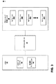
図3は、本開示の技術を実現しうる典型的なメモリ32、メモリコントローラ34、及びフロントエンド処理ユニット36を示すブロック図である。図3の要素32、34、及び36は、それぞれ図1の要素8、10、及び6に対応しうるが、これらの要素はその他のデバイス内でも同様に用いられることができる。図3に示すように、メモリ32は、生データバッファ42と処理済データバッファ44とを含む。生データバッファ42は一般に生画像データを格納し、処理済データバッファは一般に、例えばフロントエンド処理ユニット36によって実行される1つ又は複数の処理ステップに従って処理されたデータを格納する。メモリ32(及び生データバッファ42と処理済データバッファ44)は、単一のメモリ場所、又は例えばメモリ8及び14(図1)のような複数の場所に位置づけられることができる。
FIG. 3 is a block diagram illustrating an
メモリコントローラ34は、メモリ32内でのメモリ構成を制御する。メモリコントローラ34は特に、メモリ32からユニット36へのメモリのロード及びユニット36からメモリ32への書き戻しを制御する。また、フロントエンド処理ユニット36内で用いられるラインバッファよりも大きいライン幅を定める大きな画像に関して、メモリコントローラ34は、生データバッファ42内の生データについて、そのようなラインバッファに収まる縦縞を定める。図2に示す画像28の縦縞27が1つのこのような例である。
The
フロントエンド処理ユニット36は、複数の画像処理モジュール45A乃至45D(集合的にモジュール45)を含むことができる。モジュール45のうちの1つ又は複数が、図2に示すラインバッファ25を含むことができる。例えばモジュール45は、例えば2次元フィルタリングモジュールや高次元フィルタリングモジュール、デモザイクモジュール、レンズロールオフ補正モジュール、拡大縮小モジュール、1つ又は複数の色補正モジュール、1つ又は複数の色変換モジュール、ノイズ低減フィルタリングモジュール、空間フィルタリングモジュール、又は生画像データや処理済画像データに用いられうるその他任意のタイプのイメージングモジュールのような幅広く様々な画像処理モジュールを含むことができる。
The front-end processing unit 36 may include a plurality of
モジュール45のラインバッファ内に収まる画像幅である例えばビューファインダ画像のような小さな画像に関して、メモリコントローラ34は、各画像の連続するラインをモジュール1(45A)内へロードし、処理された結果を処理済データバッファ44のうちの1つへ書き戻すことができる。処理済データはその後、モジュール2(45B)内へロードされ、更に処理され、その後書き戻されることができる。更なる処理済データはその後、モジュール3内へロードされ、処理され、書き戻され、このような処理は、ユニット36内のモジュール45のうちのいくつか又は全てを通して続くことができる。あるいは、小さな画像に関して、小さな画像に関する生データが画像取得装置(図3に示さず)から直接来る場合、画像取得装置12(図1)の出力が、ユニット36によって定められる画像処理パイプラインへ直接接続されることができる。この場合において、小さなビューファインダ画像に関する生データは、ラインバッファ内での処理の前に、メモリコントローラ34を通らず、(例えば32のような)異なるメモリ内に格納もされない。これは、リアルタイムで表示される必要があるこのような小さな画像に関する処理速度を向上させることができる。
For a small image, such as a viewfinder image, that is an image width that fits in the line buffer of module 45, the
所与のラインが一度モジュール1(45A)によって処理されると、その後次のラインがパイプライン形式で処理されることができる。従って、モジュール45のラインバッファ内に収まるライン幅を有する小さなビューファインダ画像に関して、画像の連続するラインが、非常に高速な画像処理スループットによってモジュール45を通してパイプラインされることができる。 Once a given line is processed by module 1 (45A), the next line can then be processed in a pipelined fashion. Thus, for a small viewfinder image having a line width that fits within the line buffer of module 45, successive lines of the image can be pipelined through module 45 with very fast image processing throughput.
大きな画像も同様の形式で処理されることができるが、最初に、ラインバッファ内に収まる縦縞へ分割される必要がある。従って、例えばデバイスによって取得される静止画像のような大きな画像に関して、メモリコントローラ34は、2次元フィルタリングの場合、(例えば、アドレッシングスキームによって)生データを互いにオーバーラップしうる縦縞として定める。この場合において、縦縞のラインは、モジュール45内へロードされ、パイプライン形式で書き戻されることができる。モジュール45のうちの1つ又は複数によって用いられるラインバッファの各々が、大きな画像の全体幅よりも小さいために、このような大きな画像の処理において更なるレイテンシが生成される。しかし、ラインバッファの大きさを低減することによって達成されるハードウェア低減は、デバイスによって取得される静止画像において許容されることのできるレイテンシという犠牲を払っても望ましい。ほとんどの場合において、ユニット36は、処理済の各ラインを、メモリコントローラ34を通って往復して送ることなしに、各縦縞のラインをパイプライン形式で処理することができる。
Large images can be processed in a similar manner, but first need to be divided into vertical stripes that fit within the line buffer. Thus, for large images, such as still images acquired by a device, for example, the
図4は、大きな画像や小さな画像の処理において小さなラインバッファが用いられる技術を示すフロー図である。この例において、大きな画像は、静止画像モードでデバイスによって取得された静止画像であり、小さな画像は、ビューファインダモードでデバイスによって取得されたビューファインダ画像である。しかし同じ技術が、互いと比較して大きな画像と小さな画像である任意の画像において用いられることができる。図4は、図2のラインバッファ25が図1のフロントエンド処理ユニット18内で用いられ、図1及び図2に関して説明される。
FIG. 4 is a flow diagram illustrating a technique in which a small line buffer is used in processing large and small images. In this example, the large image is a still image acquired by the device in the still image mode, and the small image is a viewfinder image acquired by the device in the viewfinder mode. However, the same technique can be used on any image that is a large image and a small image compared to each other. FIG. 4 is described with respect to FIGS. 1 and 2 in which the line buffer 25 of FIG. 2 is used in the front
図4に示すように、画像取得装置12は、小さなビューファインダ画像又は大きな静止画像でありうる画像を取得する(51)。デバイス2のモードは、この画像がビューファインダ画像であるか静止画像であるかを判定する(52)。小さなビューファインダ画像の場合(52のビューファインダ分岐)、画像取得装置12によって取得された生画像データが、フロントエンド処理ユニット18のラインバッファ25へ直接ロードされる。本明細書で説明するように、ラインバッファ25はビューファインダ画像の全体幅を収納できる幅を有することによって、これらの画像がフロントエンド処理ユニット18内でラインごとに処理されることを可能とする。その結果、図4に示すように、フロントエンド処理ユニット18は、ラインバッファ25を用いて画像を処理する(56)。その後メモリコントローラによって、処理済画像はメモリ8(又はメモリ14)内へ再び格納される(57)。もし望まれれば、追加の処理ステップが続いて画像に実行されることができる。
As shown in FIG. 4, the
大きな静止画像の場合(52の静止画像分岐)、メモリコントローラ10が静止画像の生データを格納し(59)、ローカルメモリ8内のメモリバッファ内で、静止画像のオーバーラップする縦縞を定める(54)。縦縞に関するメモリバッファは、ラインバッファの幅に従う大きさであることができ、縦縞は、静止画像のオーバーラップする縞であることができる。メモリコントローラ10はその後、フロントエンド処理ユニット18のラインバッファ25内へ縦縞の各行をロードする(55)。このようにして、ユニット18はラインバッファ25を用いて静止画像を処理することができるが(56)、静止画像の各ラインについてではなく、縦縞の各ラインについて処理する。このような処理後、メモリコントローラによって、処理済画像はメモリ8(又はメモリ14)内へ再び格納される(57)。こちらでも、もし望まれれば、追加の処理ステップが続いて画像に実行されうる。言い換えると、図4に示す処理は画像処理の1つの段階に適応するが、例えばもしフロントエンド処理ユニット18がラインバッファを用いるいくつかの画像処理モジュールを含む場合、連続する段階について反復されることができる。更に、ビューファインダ画像の各ライン又は静止画像の縦縞の各ラインは、フロントエンド処理ユニット18を通してパイプラインされることができる。
In the case of a large still image (52 still image branch), the memory controller 10 stores the raw data of the still image (59), and defines vertical stripes that overlap the still image in the memory buffer in the local memory 8 (54). ). The memory buffer for vertical stripes can be sized according to the width of the line buffer, and the vertical stripes can be overlapping stripes of still images. The memory controller 10 then loads each row of vertical stripes into the line buffer 25 of the front end processing unit 18 (55). In this way, the
多くの画像処理技術が説明された。この技術は、ハードウェア、ソフトウェア、ファームウェア、又はこれらの任意の組み合わせによって実現されうる。ソフトウェアによって実現される場合、この技術は、2つ又はそれより多くの異なる大きさの画像を取得するデバイス内で実行されると、そのような画像を、少なくともいくつかの画像の幅よりも小さいラインバッファを用いて処理することができるプログラムコードを備えるコンピュータ読取可能媒体を示されうる。この場合、コンピュータ読取可能媒体は、例えば同期ランダムアクセスメモリ(SDRAM)のようなランダムアクセスメモリ(RAM)、読取専用メモリ(ROM)、不揮発性ランダムアクセスメモリ(NVRAM)、電気消去可能プログラマブル読取専用メモリ(EEPROM)、フラッシュメモリ、又はこれらと同様のものを備える。 A number of image processing techniques have been described. This technique may be realized by hardware, software, firmware, or any combination thereof. When implemented in software, this technique, when executed in a device that acquires two or more differently sized images, makes such images smaller than the width of at least some images. A computer readable medium comprising program code that can be processed using a line buffer may be shown. In this case, the computer readable medium is, for example, a random access memory (RAM) such as a synchronous random access memory (SDRAM), a read only memory (ROM), a nonvolatile random access memory (NVRAM), or an electrically erasable programmable read only memory. (EEPROM), flash memory, or the like.
プログラムコードは、コンピュータ読取可能命令の形式でメモリに格納されることができる。この場合、例えばDSPのようなプロセッサが、1つ又は複数の画像処理技術を実行するために、メモリ内に格納された命令を実行することができる。いくつかの場合において、この技術は、様々なハードウェア部品に画像処理を加速させるDSPによって実行されることができる。他の場合において、本明細書で説明されたユニットは、マイクロプロセッサ、1つ又は複数の特定用途向け集積回路(ASIC)、1つ又は複数のフィールド・プログラマブル・ゲート・アレイ(FPGA)、又はその他いくつかのハードウェアとソフトウェアとの組み合わせとして実現されうる。 The program code can be stored in memory in the form of computer readable instructions. In this case, a processor such as a DSP may execute instructions stored in the memory to perform one or more image processing techniques. In some cases, this technique can be performed by a DSP that accelerates image processing to various hardware components. In other cases, the units described herein may include a microprocessor, one or more application specific integrated circuits (ASICs), one or more field programmable gate arrays (FPGAs), or others. It can be realized as a combination of some hardware and software.
それにもかかわらず、本明細書で説明された技術への様々な変形例が可能である。例えば、この技術は、主として小さなビューファインダ画像及び大きな静止画像の状況において説明されたが、異なる幅の任意の画像に関して適用することができる。また、この技術は、高解像度画像及び低解像度画像に関して適用することができ、いずれの場合も、高解像度画像が低解像度画像よりも高いピクセル密度を定めている限り、高解像度画像は、与えられた画像サイズについて、幅が大きくなるであろう。更に、この技術は個々の画像の文脈において説明されたが、ビデオシーケンスを形成する画像のセットにも用いることができる。この場合、低解像度シーケンスがバッファ内でラインごとに処理されることができるのに対し、高解像度シーケンスは縦縞として格納され、その後処理されることができる。これらの実施形態及びその他の実施形態は、特許請求の範囲の範囲内である。 Nevertheless, various modifications to the techniques described herein are possible. For example, although this technique has been described primarily in the context of small viewfinder images and large still images, it can be applied to any image of different width. This technique can also be applied to high and low resolution images, in which case, as long as the high resolution image defines a higher pixel density than the low resolution image, the high resolution image is given. For different image sizes, the width will be larger. Furthermore, although this technique has been described in the context of individual images, it can also be used with a set of images that form a video sequence. In this case, the low resolution sequence can be processed line by line in the buffer, whereas the high resolution sequence can be stored as vertical stripes and then processed. These and other embodiments are within the scope of the claims.
Claims (25)
前記第1の画像の画像幅を収納できる大きさのラインバッファを用いて前記第1の画像を処理することと、
前記デバイスを用いて、前記第1の画像の画像幅よりも大きい画像幅を有する第2の画像を取得することと、
前記ラインバッファを用いて、前記ラインバッファ内に収まる幅を定める前記第2の画像の縦縞を処理することと
を備える方法。 Acquiring a first image using a device;
Processing the first image using a line buffer sized to accommodate the image width of the first image;
Using the device to obtain a second image having an image width greater than the image width of the first image;
Using the line buffer to process vertical stripes in the second image defining a width that fits within the line buffer.
前記画像の幅よりも小さい幅を定めるラインバッファを用いて、前記画像の縦縞を処理することと
を備える方法。 Acquiring images using the device,
Processing the vertical stripes of the image using a line buffer that defines a width smaller than the width of the image.
前記デバイスを用いてビューファインダ画像を取得することと、
前記ビューファインダ画像を収納できる幅のラインバッファを用いて前記ビューファインダ画像を処理することと
を備える請求項6に記載の方法。 The image is a still image, and the method further includes:
Obtaining a viewfinder image using the device;
7. The method of claim 6, comprising processing the viewfinder image using a line buffer that is wide enough to accommodate the viewfinder image.
メモリと、
前記画像のオーバーラップする縦縞を定めるメモリコントローラと、
前記画像の幅よりも小さい幅を定めるラインバッファを用いて、前記画像のオーバーラップする縦縞を処理する処理ユニットと
を備えるデバイス。 An image acquisition device for acquiring images;
Memory,
A memory controller that defines overlapping vertical stripes of the image;
A processing unit for processing overlapping vertical stripes of the image using a line buffer that defines a width smaller than the width of the image.
前記画像取得装置はビューファインダ画像を取得し、
前記処理ユニットは、前記ビューファインダ画像を収納できる幅の前記ラインバッファを用いて、前記ビューファインダ画像を処理する請求項10に記載のデバイス。 The image is a still image;
The image acquisition device acquires a viewfinder image,
The device according to claim 10, wherein the processing unit processes the viewfinder image using the line buffer having a width capable of accommodating the viewfinder image.
第1の画像の画像幅を収納できる大きさのラインバッファを用いて前記第1の画像を処理し、
前記ラインバッファを用いて第2の画像の縦縞を処理し、前記第2の画像は前記第1の画像の画像幅よりも大きく、前記ラインバッファよりも大きい画像幅を有し、前記第2の画像の縦縞は前記ラインバッファ内に収まる幅を定めるフロントエンド処理ユニット。 A front end processing unit for processing images acquired by a device, the processing unit comprising:
Processing the first image using a line buffer large enough to accommodate the image width of the first image;
Processing the vertical stripes of the second image using the line buffer, wherein the second image is larger than the image width of the first image and larger than the line buffer, and the second image A front-end processing unit that determines the width within which vertical stripes of an image fit within the line buffer.
第1の画像の画像幅を収納できるサイズのラインバッファを用いて前記第1の画像を処理させ、
前記ラインバッファを用いて第2の画像の縦縞を処理させ、
前記第2の画像は前記第1の画像の画像幅よりも大きく、前記ラインバッファよりも大きい画像幅を有し、前記第2の画像の縦縞は前記ラインバッファ内に収まる幅を定めるコンピュータ読取可能媒体。 A computer readable medium comprising instructions, wherein when the instructions are executed in a device, the device
Processing the first image using a line buffer sized to accommodate the image width of the first image;
Processing the vertical stripes of the second image using the line buffer;
The second image is larger than the image width of the first image and has a larger image width than the line buffer, and the vertical stripes of the second image define a width that fits within the line buffer. Medium.
Applications Claiming Priority (2)
| Application Number | Priority Date | Filing Date | Title |
|---|---|---|---|
| US11/402,661 US7595805B2 (en) | 2006-04-11 | 2006-04-11 | Techniques to facilitate use of small line buffers for processing of small or large images |
| PCT/US2007/066353 WO2007121197A1 (en) | 2006-04-11 | 2007-04-10 | Techniques to facilitate use of small line buffers for processing of small or large images |
Related Child Applications (1)
| Application Number | Title | Priority Date | Filing Date |
|---|---|---|---|
| JP2012113301A Division JP2012212436A (en) | 2006-04-11 | 2012-05-17 | Techniques to facilitate use of small line buffers for processing small or large images |
Publications (2)
| Publication Number | Publication Date |
|---|---|
| JP2009533772A true JP2009533772A (en) | 2009-09-17 |
| JP2009533772A5 JP2009533772A5 (en) | 2011-11-17 |
Family
ID=38328664
Family Applications (4)
| Application Number | Title | Priority Date | Filing Date |
|---|---|---|---|
| JP2009505581A Withdrawn JP2009533772A (en) | 2006-04-11 | 2007-04-10 | Technology that easily uses small line buffers to process small or large images |
| JP2012113301A Pending JP2012212436A (en) | 2006-04-11 | 2012-05-17 | Techniques to facilitate use of small line buffers for processing small or large images |
| JP2013027486A Withdrawn JP2013146080A (en) | 2006-04-11 | 2013-02-15 | Techniques to facilitate use of small line buffers for processing small or large images |
| JP2015016974A Withdrawn JP2015144435A (en) | 2006-04-11 | 2015-01-30 | Techniques to facilitate use of small line buffers for processing of small or large images |
Family Applications After (3)
| Application Number | Title | Priority Date | Filing Date |
|---|---|---|---|
| JP2012113301A Pending JP2012212436A (en) | 2006-04-11 | 2012-05-17 | Techniques to facilitate use of small line buffers for processing small or large images |
| JP2013027486A Withdrawn JP2013146080A (en) | 2006-04-11 | 2013-02-15 | Techniques to facilitate use of small line buffers for processing small or large images |
| JP2015016974A Withdrawn JP2015144435A (en) | 2006-04-11 | 2015-01-30 | Techniques to facilitate use of small line buffers for processing of small or large images |
Country Status (6)
| Country | Link |
|---|---|
| US (1) | US7595805B2 (en) |
| EP (1) | EP2008238A1 (en) |
| JP (4) | JP2009533772A (en) |
| KR (1) | KR100997619B1 (en) |
| CN (1) | CN101416217B (en) |
| WO (1) | WO2007121197A1 (en) |
Families Citing this family (10)
| Publication number | Priority date | Publication date | Assignee | Title |
|---|---|---|---|---|
| TWI397885B (en) * | 2008-05-07 | 2013-06-01 | Novatek Microelectronics Corp | Method for accessing data for timing controller in flat panel display and related flat panel display |
| TWI413943B (en) * | 2009-02-11 | 2013-11-01 | Silicon Motion Inc | Image processing system and method thereof |
| US9367501B2 (en) * | 2011-11-10 | 2016-06-14 | International Business Machines Corporation | Dynamic streaming data dispatcher |
| WO2013138910A1 (en) | 2012-03-19 | 2013-09-26 | Michael Klein | Virtual respiratory gas delivery systems and circuits |
| WO2017138233A1 (en) * | 2016-02-12 | 2017-08-17 | 株式会社リコー | Image processing device, image processing system and image processing method |
| US10380969B2 (en) * | 2016-02-28 | 2019-08-13 | Google Llc | Macro I/O unit for image processor |
| KR102637732B1 (en) | 2018-09-21 | 2024-02-19 | 삼성전자주식회사 | Image signal processor, method of operating the image signal processor, and application processor including the image signal processor |
| KR20200094500A (en) * | 2019-01-30 | 2020-08-07 | 삼성전자주식회사 | Electronic device and method for processing line data included in image frame data into multiple intervals |
| CN111314579B (en) * | 2020-02-21 | 2021-10-15 | 苏州浪潮智能科技有限公司 | Method and chip for vertical filtering processing of image |
| CN113709494B (en) * | 2021-06-23 | 2024-04-09 | 珠海全志科技股份有限公司 | Image decompression method and device for super-resolution reconstruction |
Citations (3)
| Publication number | Priority date | Publication date | Assignee | Title |
|---|---|---|---|---|
| JP2002304624A (en) * | 2001-04-05 | 2002-10-18 | Canon Inc | Filter processor and imaging device |
| JP2005203964A (en) * | 2004-01-14 | 2005-07-28 | Fuji Photo Film Co Ltd | Digital camera |
| JP2006005596A (en) * | 2004-06-17 | 2006-01-05 | Renesas Technology Corp | Semiconductor integrated circuit device and imaging device |
Family Cites Families (11)
| Publication number | Priority date | Publication date | Assignee | Title |
|---|---|---|---|---|
| US6473123B1 (en) * | 1997-08-21 | 2002-10-29 | Flash Point Technology, Inc. | Method and system for organizing DMA transfers to support image rotation |
| JPH11112753A (en) * | 1997-10-02 | 1999-04-23 | Ricoh Co Ltd | Picture processor |
| EP1013089B1 (en) * | 1997-10-06 | 2005-06-22 | Silicon Image, Inc. | Digital video system and methods for providing same |
| JP3510997B2 (en) * | 1999-04-05 | 2004-03-29 | セイコーエプソン株式会社 | Image processing device and copy system |
| JP3720268B2 (en) | 2001-02-26 | 2005-11-24 | 株式会社メガチップス | Image processing device |
| CN1266582C (en) * | 2001-05-06 | 2006-07-26 | 中兴通讯股份有限公司 | Large-view blocking and buffering display method |
| JP2003116048A (en) * | 2001-10-05 | 2003-04-18 | Hitachi Kokusai Electric Inc | Shading correcting method |
| KR100940203B1 (en) * | 2003-02-18 | 2010-02-10 | 삼성전자주식회사 | Method and apparatus for processing pixel based on segments |
| KR100612414B1 (en) * | 2003-04-28 | 2006-08-16 | 삼성전자주식회사 | Image data processing system and method for reading and writing image data |
| US6999105B2 (en) | 2003-12-04 | 2006-02-14 | International Business Machines Corporation | Image scaling employing horizontal partitioning |
| JP4219887B2 (en) | 2004-12-28 | 2009-02-04 | 富士通マイクロエレクトロニクス株式会社 | Image processing apparatus and image processing method |
-
2006
- 2006-04-11 US US11/402,661 patent/US7595805B2/en active Active
-
2007
- 2007-04-10 WO PCT/US2007/066353 patent/WO2007121197A1/en active Application Filing
- 2007-04-10 EP EP07760421A patent/EP2008238A1/en not_active Withdrawn
- 2007-04-10 JP JP2009505581A patent/JP2009533772A/en not_active Withdrawn
- 2007-04-10 KR KR1020087027569A patent/KR100997619B1/en active IP Right Grant
- 2007-04-10 CN CN2007800125768A patent/CN101416217B/en active Active
-
2012
- 2012-05-17 JP JP2012113301A patent/JP2012212436A/en active Pending
-
2013
- 2013-02-15 JP JP2013027486A patent/JP2013146080A/en not_active Withdrawn
-
2015
- 2015-01-30 JP JP2015016974A patent/JP2015144435A/en not_active Withdrawn
Patent Citations (3)
| Publication number | Priority date | Publication date | Assignee | Title |
|---|---|---|---|---|
| JP2002304624A (en) * | 2001-04-05 | 2002-10-18 | Canon Inc | Filter processor and imaging device |
| JP2005203964A (en) * | 2004-01-14 | 2005-07-28 | Fuji Photo Film Co Ltd | Digital camera |
| JP2006005596A (en) * | 2004-06-17 | 2006-01-05 | Renesas Technology Corp | Semiconductor integrated circuit device and imaging device |
Also Published As
| Publication number | Publication date |
|---|---|
| CN101416217A (en) | 2009-04-22 |
| US20070236511A1 (en) | 2007-10-11 |
| KR20080108616A (en) | 2008-12-15 |
| JP2015144435A (en) | 2015-08-06 |
| JP2012212436A (en) | 2012-11-01 |
| CN101416217B (en) | 2012-08-08 |
| US7595805B2 (en) | 2009-09-29 |
| WO2007121197A1 (en) | 2007-10-25 |
| JP2013146080A (en) | 2013-07-25 |
| EP2008238A1 (en) | 2008-12-31 |
| KR100997619B1 (en) | 2010-12-01 |
Similar Documents
| Publication | Publication Date | Title |
|---|---|---|
| JP2013146080A (en) | Techniques to facilitate use of small line buffers for processing small or large images | |
| US9554038B1 (en) | Camera system transmission in bandwidth constrained environments | |
| US20090073277A1 (en) | Image processing apparatus, image processing method and image pickup apparatus | |
| US8861846B2 (en) | Image processing apparatus, image processing method, and program for performing superimposition on raw image or full color image | |
| US9332212B2 (en) | Imaging apparatus with improved pre-processing | |
| CN1697483A (en) | Image display device | |
| KR20220066917A (en) | Image dewarping system | |
| US8531538B2 (en) | Image processing apparatus, imaging apparatus, and image processing method | |
| KR101009108B1 (en) | Image processing apparatus and image processing method | |
| US7688361B2 (en) | Image processor including memory controller which starts reading image data before writing screenful of image data is completed | |
| US8045021B2 (en) | Memory organizational scheme and controller architecture for image and video processing | |
| US7496235B2 (en) | Scan line to block re-ordering buffer for image compression | |
| JP2004312072A (en) | Image processing device, camera, and image processing method | |
| WO2011055483A1 (en) | Image capture device | |
| US9565378B2 (en) | Imaging device | |
| JP4720494B2 (en) | Imaging apparatus, imaging method and program, and recording medium | |
| TWI516088B (en) | Image system | |
| US9277145B2 (en) | Imaging device dividing imaging region into first divided image data and second divided image data | |
| JP2013187630A (en) | Picture processing device and method, and imaging device | |
| JP2005159596A (en) | Digital camera |
Legal Events
| Date | Code | Title | Description |
|---|---|---|---|
| A977 | Report on retrieval |
Free format text: JAPANESE INTERMEDIATE CODE: A971007 Effective date: 20110323 |
|
| A131 | Notification of reasons for refusal |
Free format text: JAPANESE INTERMEDIATE CODE: A131 Effective date: 20110329 |
|
| A601 | Written request for extension of time |
Free format text: JAPANESE INTERMEDIATE CODE: A601 Effective date: 20110629 |
|
| A602 | Written permission of extension of time |
Free format text: JAPANESE INTERMEDIATE CODE: A602 Effective date: 20110706 |
|
| A524 | Written submission of copy of amendment under section 19 (pct) |
Free format text: JAPANESE INTERMEDIATE CODE: A524 Effective date: 20110927 |
|
| A02 | Decision of refusal |
Free format text: JAPANESE INTERMEDIATE CODE: A02 Effective date: 20120117 |
|
| A521 | Written amendment |
Free format text: JAPANESE INTERMEDIATE CODE: A523 Effective date: 20120517 |
|
| A911 | Transfer to examiner for re-examination before appeal (zenchi) |
Free format text: JAPANESE INTERMEDIATE CODE: A911 Effective date: 20120525 |
|
| A912 | Re-examination (zenchi) completed and case transferred to appeal board |
Free format text: JAPANESE INTERMEDIATE CODE: A912 Effective date: 20120727 |
|
| A601 | Written request for extension of time |
Free format text: JAPANESE INTERMEDIATE CODE: A601 Effective date: 20130206 |
|
| A602 | Written permission of extension of time |
Free format text: JAPANESE INTERMEDIATE CODE: A602 Effective date: 20130212 |
|
| A761 | Written withdrawal of application |
Free format text: JAPANESE INTERMEDIATE CODE: A761 Effective date: 20130725 |