JP2009528571A - Optical display with grooved optical plate - Google Patents
Optical display with grooved optical plate Download PDFInfo
- Publication number
- JP2009528571A JP2009528571A JP2008557320A JP2008557320A JP2009528571A JP 2009528571 A JP2009528571 A JP 2009528571A JP 2008557320 A JP2008557320 A JP 2008557320A JP 2008557320 A JP2008557320 A JP 2008557320A JP 2009528571 A JP2009528571 A JP 2009528571A
- Authority
- JP
- Japan
- Prior art keywords
- layer
- light management
- light
- connecting member
- management layer
- Prior art date
- Legal status (The legal status is an assumption and is not a legal conclusion. Google has not performed a legal analysis and makes no representation as to the accuracy of the status listed.)
- Withdrawn
Links
Images


Classifications
-
- G—PHYSICS
- G02—OPTICS
- G02F—OPTICAL DEVICES OR ARRANGEMENTS FOR THE CONTROL OF LIGHT BY MODIFICATION OF THE OPTICAL PROPERTIES OF THE MEDIA OF THE ELEMENTS INVOLVED THEREIN; NON-LINEAR OPTICS; FREQUENCY-CHANGING OF LIGHT; OPTICAL LOGIC ELEMENTS; OPTICAL ANALOGUE/DIGITAL CONVERTERS
- G02F1/00—Devices or arrangements for the control of the intensity, colour, phase, polarisation or direction of light arriving from an independent light source, e.g. switching, gating or modulating; Non-linear optics
- G02F1/01—Devices or arrangements for the control of the intensity, colour, phase, polarisation or direction of light arriving from an independent light source, e.g. switching, gating or modulating; Non-linear optics for the control of the intensity, phase, polarisation or colour
- G02F1/13—Devices or arrangements for the control of the intensity, colour, phase, polarisation or direction of light arriving from an independent light source, e.g. switching, gating or modulating; Non-linear optics for the control of the intensity, phase, polarisation or colour based on liquid crystals, e.g. single liquid crystal display cells
- G02F1/133—Constructional arrangements; Operation of liquid crystal cells; Circuit arrangements
- G02F1/1333—Constructional arrangements; Manufacturing methods
- G02F1/1335—Structural association of cells with optical devices, e.g. polarisers or reflectors
- G02F1/1336—Illuminating devices
- G02F1/133602—Direct backlight
- G02F1/133606—Direct backlight including a specially adapted diffusing, scattering or light controlling members
-
- G—PHYSICS
- G02—OPTICS
- G02B—OPTICAL ELEMENTS, SYSTEMS OR APPARATUS
- G02B5/00—Optical elements other than lenses
- G02B5/30—Polarising elements
-
- G—PHYSICS
- G02—OPTICS
- G02F—OPTICAL DEVICES OR ARRANGEMENTS FOR THE CONTROL OF LIGHT BY MODIFICATION OF THE OPTICAL PROPERTIES OF THE MEDIA OF THE ELEMENTS INVOLVED THEREIN; NON-LINEAR OPTICS; FREQUENCY-CHANGING OF LIGHT; OPTICAL LOGIC ELEMENTS; OPTICAL ANALOGUE/DIGITAL CONVERTERS
- G02F1/00—Devices or arrangements for the control of the intensity, colour, phase, polarisation or direction of light arriving from an independent light source, e.g. switching, gating or modulating; Non-linear optics
- G02F1/01—Devices or arrangements for the control of the intensity, colour, phase, polarisation or direction of light arriving from an independent light source, e.g. switching, gating or modulating; Non-linear optics for the control of the intensity, phase, polarisation or colour
- G02F1/13—Devices or arrangements for the control of the intensity, colour, phase, polarisation or direction of light arriving from an independent light source, e.g. switching, gating or modulating; Non-linear optics for the control of the intensity, phase, polarisation or colour based on liquid crystals, e.g. single liquid crystal display cells
- G02F1/133—Constructional arrangements; Operation of liquid crystal cells; Circuit arrangements
- G02F1/1333—Constructional arrangements; Manufacturing methods
- G02F1/1335—Structural association of cells with optical devices, e.g. polarisers or reflectors
Abstract
ディスプレーシステムは、光源と、ディスプレーパネルと、光源とディスプレーパネルの間に配設された光管理層配列体とを有する。この光源は、光管理層配列体を通してディスプレーパネルを照光する。この光管理層配列体は、ディスプレーパネルに面する前面層と、光源に面する背面層と、前面及び背面層を連結する複数の連結部材とを有する溝付きプレートを備える。幾つかの実施形態では、溝付きプレートは第1の光管理層と、第1の光管理層とほぼ平行で、第1の光管理層から離隔された横断部材と、横断部材及び第1の光管理層を連結する第1の連結部材配列体とを備える。 The display system includes a light source, a display panel, and a light management layer array disposed between the light source and the display panel. The light source illuminates the display panel through the light management layer array. The light management layer array includes a grooved plate having a front layer facing the display panel, a back layer facing the light source, and a plurality of connecting members connecting the front and back layers. In some embodiments, the fluted plate includes a first light management layer, a transverse member substantially parallel to the first light management layer and spaced from the first light management layer, the transverse member and the first A first connecting member array for connecting the light management layers.
Description
本発明は、光学ディスプレーと、より具体的にはLCDモニター及びLCDテレビジョンに使用できるような、背後から照明されるディスプレーシステムに関する。 The present invention relates to an optical display and more particularly to a display system illuminated from the back, which can be used for LCD monitors and LCD televisions.
液晶ディスプレー(LCD)は、ラップトップコンピュータ、手持ち式計算器、デジタル時計及びテレビなどのデバイスに使用される光学ディスプレーである。LCDの中には、ディスプレーの側面に位置する光源を、光源からパネルの背面まで光を誘導するように配置される導光器と合わせて備えるものもある。他のLCDの中には、例えば、一部のLCDモニター及びLCDテレビジョン(LCD−TV)、LCDパネルの背後に配置される多数の光源を使用して直接照明されるものある。ある特定のレベルのディスプレーの明るさを達成するための、所要光出力はディスプレーのサイズの二乗と共に増大するのに対して、ディスプレーの側面に沿って光源を配置させるのに利用できるスペースはディスプレーのサイズと共に直線的に増大するだけであるため、この構成は、ディスプレーが大型になるにつれてますます普及しつつある。加えて、LCD−TVのような、LCDの用途の中には、ディスプレーが他の用途に比べてより遠い距離から視聴されるのに十分に明るいことを要求するものもあり、LCD−TVに対する所要視角がLCDモニター及び手持ち式デバイスに対するものとは概して異なっている。 Liquid crystal displays (LCDs) are optical displays used in devices such as laptop computers, handheld calculators, digital watches and televisions. Some LCDs include a light source located on the side of the display, along with a light guide that is arranged to direct light from the light source to the back of the panel. Some other LCDs, for example, some LCD monitors and LCD televisions (LCD-TVs), are directly illuminated using a number of light sources located behind the LCD panel. The required light output to achieve a certain level of display brightness increases with the square of the display size, whereas the space available to place the light source along the side of the display is This configuration is becoming increasingly popular as the display becomes larger, since it only increases linearly with size. In addition, some LCD applications, such as LCD-TV, require the display to be bright enough to be viewed from a greater distance than other applications. The required viewing angle is generally different from that for LCD monitors and handheld devices.
一部のLCDモニター及び大部分のLCD−TVは、一般的には多数の冷陰極蛍光ランプ(CCFL)により背後から照明されている。これら光源は線状であり、ディスプレーの幅一杯にわたって伸延しており、結果としてディスプレーの背面が、黒い部分で分けられた一連の明るい細長いストリップで照光される。このような照明プロファイルは、望ましくはない、したがって拡散プレートがLCD装置の背後において照明プロファイルを平滑にするために使用される。 Some LCD monitors and most LCD-TVs are typically illuminated from behind by a number of cold cathode fluorescent lamps (CCFLs). These light sources are linear and extend the full width of the display, so that the back of the display is illuminated with a series of bright elongated strips separated by black portions. Such an illumination profile is undesirable and therefore a diffuser plate is used to smooth the illumination profile behind the LCD device.
現在、LCD−TV拡散プレートは、ガラス、ポリスチレンビード、及びCaCO3粒子を含む様々な分散相と組み合わされた、ポリメチルメタクリレート(PMMA)の高分子マトリックス、ポリ(カーボネート)、シクロオレフィン類、ポリメチルメタクリレート又はポリスチレンのランダム共重合体類を採用している。これらプレートは、多くの場合ランプの高温に曝された後変形又は反れてしまう。さらに、一部の拡散プレートは、LCDパネルの背面での照明プロファイルをもっと均一にしようとして、その幅にわたって空間的に変動する拡散特性を有している。かかる不均一な拡散体は時としてプリントパターン拡散体(printed pattern diffuser)と呼ばれる。拡散パターンは、組み立てるときに照明光源にレジストしなければならないので、これらを製造するのには費用がかかり、製造原価も高くなる。加えて、高分子マトリックス全体に均一に拡散粒子を分配するためにカスタマイズされた押出成型化合物(extrusion compounding)が必要となり、コストがさらに高くなる。 Currently, LCD-TV diffuser plates are a polymer matrix of polymethyl methacrylate (PMMA), poly (carbonates), cycloolefins combined with various dispersed phases including glass, polystyrene beads, and C a CO 3 particles. Random copolymers of polymethyl methacrylate or polystyrene are employed. These plates often deform or warp after being exposed to the high temperature of the lamp. In addition, some diffusion plates have diffusion characteristics that vary spatially across their width in an attempt to make the illumination profile at the back of the LCD panel more uniform. Such non-uniform diffusers are sometimes referred to as printed pattern diffusers. Since diffusion patterns must be resisted to the illumination source when assembled, they are expensive to manufacture and expensive to manufacture. In addition, customized extrusion compounding is required to distribute the diffusing particles uniformly throughout the polymer matrix, further increasing costs.
さらに、反り又は他のタイプの物理的変形を防止するために、拡散プレートはその高さ及び幅を基準として最小厚さのものでなければならない。ディスプレーのサイズが増大するにつれて、これは拡散プレートもますます厚くなり、したがって、ディスプレーの重量を増加させることを意味する。 Further, to prevent warping or other types of physical deformation, the diffuser plate must be of a minimum thickness with respect to its height and width. As the size of the display increases, this means that the diffuser plate will also become thicker, thus increasing the weight of the display.
本発明の一実施形態は、光源と、ディスプレーパネルと、光源とディスプレーパネルとの間に配設された光管理層配列体とを有するディスプレーシステムを目的とする。この光源は、光管理層配列体を通ってディスプレーパネルを照光する。この光管理層配列体は、ディスプレーパネルに面する前面層と、光源に面する背面層と、前面及び背面層を連結する複数の連結部材とを有する溝付きプレートを備える。 One embodiment of the present invention is directed to a display system having a light source, a display panel, and a light management layer array disposed between the light source and the display panel. The light source illuminates the display panel through the light management layer array. The light management layer array includes a grooved plate having a front layer facing the display panel, a back layer facing the light source, and a plurality of connecting members connecting the front and back layers.
本発明の別の実施形態は、溝付き層を備える光管理装置を対象とする。この溝付き層は、第1の光管理層と、第1の光管理層とほぼ平行であり、第1の光管理層から離隔された横断部材と、横断部材を第1の光管理層に連結する第1の連結部材配列体とを有する。 Another embodiment of the invention is directed to a light management device comprising a grooved layer. The grooved layer is substantially parallel to the first light management layer, the first light management layer, the transverse member spaced from the first light management layer, and the transverse member as the first light management layer. A first connecting member array to be connected.
本願のこれらの態様及び他の態様は、以下の詳細な説明から明らかとなるだろう。しかし、上記要約は、請求された主題に関する限定として決して解釈されるべきでなく、主題は、添付の特許請求の範囲によってのみ規定され、実行の間補正されてもよい。 These and other aspects of the present application will be apparent from the detailed description below. However, the above summary should in no way be construed as a limitation on the claimed subject matter, which is defined only by the appended claims and may be amended during execution.
本発明は、液晶ディスプレー(LCD、又はLCディスプレー)に適用可能であり、背後から直接照明されるLCD及びエッジ照明されるLCD、例えば、LCDモニター及びLCDテレビジョン(LCD−TV)に使用されるLCDに適用可能である。 The present invention is applicable to liquid crystal displays (LCD or LC displays) and is used for LCDs that are directly illuminated from behind and edge illuminated LCDs such as LCD monitors and LCD televisions (LCD-TVs). Applicable to LCD.
LCD−TVに現在使用されている拡散プレートは、高分子マトリックス、例えば、剛性シートとして形成される、ポリメチルメタクリレート(PMMA)、ポリカーボネート(PC)、又はシクロオレフィン類をベースにしている。このシートは、拡散粒子、例えば、有機粒子、無機粒子又は空間(泡)を含有する。これらのプレートは、ディスプレーを照光するために使用される光源の高温に曝された後に、多くの場合変形したり反ったりする。これらのプレートはまた、作製し、最終のディスプレーデバイスに組立てるのがより高価である。 Diffuser plates currently used in LCD-TV are based on polymer matrices, such as polymethyl methacrylate (PMMA), polycarbonate (PC), or cycloolefins, which are formed as rigid sheets. This sheet contains diffusing particles, for example, organic particles, inorganic particles or spaces (bubbles). These plates often deform and warp after being exposed to the high temperatures of the light source used to illuminate the display. These plates are also more expensive to make and assemble into the final display device.
本出願は、LCDパネルそれ自身と光源との間に配置される光管理層配列体を有する直接照明式LCD装置を開示する。この光管理層配列体は、その透過率及びかすみ(ヘイズ)レベルが、その明るさがディスプレーにわたって比較的に均一である直接照明LCディスプレーを提供するように構成される拡散層を備えることができる。 The present application discloses a directly illuminated LCD device having a light management layer array disposed between the LCD panel itself and the light source. The light management layer arrangement can comprise a diffusing layer configured to provide a direct illumination LC display whose transmittance and haze level are relatively uniform in brightness across the display. .
代表的な直接照明LCディスプレー100の概略分解図が、図1に示される。かかるディスプレーデバイス100は、例えばLCDモニター又はLCDテレビで使用されてもよい。このディスプレーデバイス100は、LCパネル102の使用に基づき、これは典型的にはパネルプレート106間に配設されたLC104の層を含む。プレート106は、多くの場合ガラスで形成され、そしてLC層104内の液晶の配向を制御するためにプレート106の内側表面上に電極構造体及びアラインメント層を備えてもよい。この電極構造体は、LCパネル画素、液晶の配向が隣接した領域とは独立して制御できるLC層の領域を規定するように一般的に配置される。カラーフィルタが、表示された画像に色を付与するために1又はそれ以上のプレート106に含まれてもよい。
A schematic exploded view of a representative direct
上方吸収偏光子108は、LC層104の上に配置され、下方吸収偏光子110はLC層104の下に配置される。例示された実施形態では、上方及び下方吸収偏光子がLCパネル102の外側に位置している。吸収偏光子108、110、及びLCパネル102は合わせてバックライト112からディスプレー100を通ってビューア(視聴者)までの光の伝達を制御する。幾つかのLCディスプレーでは、吸収偏光子108、110は、それらの透過軸を垂直にした状態で配置されてよい。LC層104の画素が駆動しない場合、そこを通過する光の偏光を変化させないことがある。したがって、下方吸収偏光子110を通過する光は、吸収偏光子108、110が垂直に整列する際は、上方吸収偏光子108によって吸収される。一方、画素が駆動される際、通過する光の偏光は回転し、それにより、下方吸収偏光子110を透過した少なくともいくらかの光も上方吸収偏光子108を透過する。例えば、コントローラ114による、LC層104の異なる画素の選択的駆動により、結果的に光が特定の望ましい場所においてディスプレーから通過し、このため、ビューアにより見られる画像を形成する。このコントローラは、例えば、コンピュータ又はテレビジョン画像を受信し、表示するテレビジョンコントローラを備えてもよい。1つ又はそれ以上の所望による層109が、例えばディスプレーの表面に機械的及び/又は環境的保護を提供するため、上方吸収偏光子108の上に設けられてもよい。例示的な一実施形態では、層109は吸収偏光子108上のハードコートを含む場合もある。
The upper absorbing
あるタイプのLCディスプレーが、上述のものとは異なる方法で動作することもあり得ることが理解されるであろう。例えば、吸収偏光子が平行に整列されてもよく、LCパネルが非駆動状態で、光の偏光を回転させることもあり得る。それにもかかわらず、このようなディスプレーの基礎構造は、上述の構造と同様のままである。 It will be appreciated that certain types of LC displays may operate in different ways than those described above. For example, absorbing polarizers may be aligned in parallel, and the LC panel may be undriven to rotate the polarization of light. Nevertheless, the basic structure of such a display remains similar to that described above.
バックライト112は、LCパネル102を照光する光を発生させる多数の光源116を備える。ディスプレーデバイス100を横断して延在する線状、冷陰極蛍光管は、ディスプレーデバイス100において光源116として一般的に使用されている。ただし、フィラメント又はアークランプ、発光ダイオード(LED)、レーザー、薄型蛍光パネル若しくは外部蛍光ランプなどの他のタイプの光源が使用されてもよい。ここに挙げた光源は、限定的又は網羅的なものを意図するのではなく、単に代表的なものであることが意図される。
The
バックライト112はまた、LCパネル102から離れる方向に、光源116から下向きに伝播する光を反射させるための反射体118を備えてもよい。この反射体118はまた、以下に説明するように、ディスプレーデバイス100の中で光をリサイクルするのに有用である。この反射体118は、鏡面反射体又は拡散反射体であってもよく、又は拡散反射体であってよい。反射体118として使用されてよい鏡面反射体の一例は、ミネソタ州、セントポールのスリーエム・カンパニー(3M Company)社から入手可能なビキュイティ(Vikuiti)(商標)鏡面反射性向上(Enhanced Specular Reflection)(ESR)フィルムである。適切な拡散反射体の例としては、拡散反射する粒子、例えば二酸化チタン、硫酸バリウム、炭酸カルシウム等が詰め込まれている重合体、例えば、ポリエチレンテレフタレート(PET)、ポリカーボネート(PC)、ポリプロピレン、ポリスチレン等が挙げられる。微小多孔質材料及び微細繊維含有材料を含む、拡散反射体の他の例は、米国特許第6,780,355号(クレットマン(Kretman)ら)に記載されている。
The
光管理層配列体120は、バックライト112とLCパネル102との間に配置される。光管理層は、ディスプレーデバイス100の動作を改善するようにバックライト112からの光伝播に影響を及ぼす。例えば、光管理層配列体120は、拡散層122を含んでもよい。この拡散層122は、光源から受けた光を拡散するために使用され、これは結果的にLCパネル102に入射する照明光の均一性の向上をもたらす。結果的に、これによって、より均一的に明るい画像がビューアにより感知されることになる。拡散層122は、その層全体にわたって分配されるバルク拡散粒子を含んでもよく、あるいは1つ以上の表面拡散構造体、又はこれらの組み合わせを含んでもよい。
The light
光管理層配列体120はまた、ゲインディヒューザー、光を概して視野方向に拡散する層を備えてもよい。幾つかの実施形態では、ゲインディヒューザーはフィルムの表面から突起する透明粒子を含有し、したがって、粒子を通過する光に光学出力を提供する。これは光の拡がり角を減少させ、その結果、軸上輝度の向上をもたらし、これは利益とみなされることもある。幾つかのタイプのゲインディヒューザーについては、米国特許第6,572,961号(コヤマ(Koyama)ら)により詳細に記載されている。
The light
光管理層配列体120はまた、反射偏光子124を含んでもよい。光源116は典型的には非偏光を発生するが下方吸収偏光子110が単一の偏光状態を透過するだけであり、このため、光源116により発生される光の約半分がLC層104に透過しない。しかしながら、この反射偏光子124は、他の方法では下方吸収偏光子に吸収される光を反射するように使用されてもよい、このため、この光は反射偏光子124と反射体118との間の反射により再利用されてよい。反射偏光子124により反射された光の少なくとも一部は偏光解消されてもよく、そしてその後反射偏光子124及び下方吸収偏光子110を通ってLC層104まで透過した偏光状態で反射偏光子124へ戻される。このようにして、反射偏光子124は光源116により発せられる光のLC層104に到達する割合を増加させるために使用されてよい、したがってディスプレーデバイス100により作成される画像がより明るい。
The light
例えば、多層光学フィルム(MOF)反射偏光子;連続分散相偏光子、ワイヤグリッド反射偏光子又はコレステリック反射偏光子などの拡散反射偏光フィルム(DRPF)といった任意の好適なタイプの反射偏光子が使用されてよい。 Any suitable type of reflective polarizer may be used, for example, a multilayer optical film (MOF) reflective polarizer; a diffusely reflective polarizing film (DRPF) such as a continuous dispersive phase polarizer, a wire grid reflective polarizer or a cholesteric reflective polarizer It's okay.
MOF及び連続分散相反射偏光子の双方は、直交する偏光状態で光を透過しながら、選択的に1つの偏光状態の光を反射するために、少なくとも2つの材料、通常では高分子材料間の屈折率の差に依拠する。MOF反射偏光子の幾つかの例が、共有米国特許第5,882,774号(ジョンザら(Jonza et al.)に記載される。MOF反射偏光子の市販されている例としては、ミネソタ州、セントポールのスリーエム・カンパニー(3M Company)社から入手可能な拡散表面を備えるVikuiti(ビキュイティ)(商標)DBEF−D200及びDBEF−D440多層反射偏光子が挙げられる。 Both MOF and continuous dispersive phase reflective polarizers transmit light in orthogonal polarization states while selectively reflecting light in one polarization state between at least two materials, usually polymeric materials. Rely on the difference in refractive index. Some examples of MOF reflective polarizers are described in co-owned US Pat. No. 5,882,774 (Jonza et al .. Commercially available examples of MOF reflective polarizers include the State of Minnesota Vikuiti (TM) DBEF-D200 and DBEF-D440 multilayer reflective polarizers with a diffusing surface available from 3M Company, St. Paul.
好適なDRPFの例としては、共有米国特許第5,825,543号(オウダーキルク(Ouderkirk)ら)に記載される連続/分散相反射偏光子及び、例えば、共有米国特許第5,867,316号(カールソン(Carlson)ら)に記載される拡散反射型多層偏光子が挙げられる。他の好適なタイプのDRPFは、米国特許第5,751,388号ラーソン(Larson)に記載される。 Examples of suitable DRPF include continuous / dispersed phase reflective polarizers described in co-owned US Pat. No. 5,825,543 (Ouderkirk et al.) And, for example, co-owned US Pat. No. 5,867,316. And a diffuse reflection type multilayer polarizer described in (Carlson et al.). Another suitable type of DRPF is described in US Pat. No. 5,751,388 Larson.
好適なワイヤグリッド偏光子の数例として、米国特許第6,122,103号(パーキンス(Perkins)ら)に記載されるものが挙げられる。なかでも、ワイヤグリッド偏光子は、ユタ州オレムのモクステック社(Moxtek Inc.)から市販されている。 Some examples of suitable wire grid polarizers include those described in US Pat. No. 6,122,103 (Perkins et al.). Among them, wire grid polarizers are commercially available from Moxtek Inc., Orem, Utah.
好適なコレステリック偏光子の数例として、例えば、米国特許第5,793,456号(ブロエル(Broer)ら)及び米国特許第6,917,399号(ペコルニー(Pekorny)ら)に記載されるものが挙げられる。コレステリック偏光子は、しばしば、コレステリック偏光子で伝達される光が直線偏光に変えられるよう、出力側の四分の一波長遅延層(quarter wave retarding layer)と共に提供される。 Some examples of suitable cholesteric polarizers are those described, for example, in US Pat. No. 5,793,456 (Broer et al.) And US Pat. No. 6,917,399 (Pekorny et al.). Is mentioned. Cholesteric polarizers are often provided with an output quarter wave retarding layer so that the light transmitted by the cholesteric polarizer can be converted to linearly polarized light.
光管理層配列体120はまた、輝度向上層128を備える。輝度向上層は、軸からずれた光の方向をディスプレーの軸により接近した方向に変える表面構造体を備えるものである。これはLC層104を通って軸上を伝播する光の量を増加させるので、ビューアが見る画像の輝度を向上させる。一例は、屈折及び反射を通して、照明光の方向を変えるかなりの数のプリズム状突起を有するプリズム状輝度向上層である。ディスプレーデバイスに使用され得るプリズム状輝度向上層としては、例えば、ミネソタ州セントポールのスリーエム・カンパニー社(3M Company)から入手可能な、BEFII 90/24、BEFII 90/50、BEFIIIM 90/50及びBEFIIITを含むプリズム・フィルムのビキュイティ(商標)BEFII及びビキュイティBEFIIIファミリーが挙げられる。
The light
光管理層配列体120はまた、他の光管理層に対して支持を提供するために使用されてよい支持層130を備えてよい。配列体によっては、他の光管理層の1つは支持層130と一体化にされてもよい。例えば、既存テレビジョンによっては、比較的に厚い(2〜3mm)、剛性なポリマーシートの中に拡散粒子を含むものもあるので、支持及び光学拡散を単一層に提供する機能を兼ね備えている。
The light
支持層130は、プレートの2つの表面間に溝、又は空間を備えるプレートである溝付きプレートを有利に備える。代表的な溝付きプレート200の断面図が、図2Aに模式的に示される。この溝付きプレート200は、第1の層202及び第2の層204、並びに第1の及び第2の層202、204をつなぐ連結部材206とを備える。連結部材206並びに第1の及び第2の層202、204により取り囲まれたこの開放空間208が溝であるとみなされてもよい。
The support layer 130 advantageously comprises a grooved plate, which is a plate with a groove or space between the two surfaces of the plate. A cross-sectional view of an exemplary
溝付きプレート200は自己支持であり、そして幾つかの例示的な実施形態では、他の光管理層に支持を提供するために使用される。溝付きプレート200は、任意の好適な材料、例えば、ポリマーなどの有機材料で製造されてよい。例えば、溝付きプレート200は、例えば、押出成形、成型などの任意の好適な方法を用いて形成されてよい。
The
溝付きプレート200の厚さ及び溝208のサイズは、特定の用途に応じて選定されてよい。例えば、溝付きプレートは数mmの厚さ、例えば、おおよそ1mm〜4mmの範囲でよく、若しくはこれより厚くてもよい。溝付きプレート200はまた、より薄くてもよい、例えば、約50μm以上の厚さを有してもよい。また、溝208の中心対中心間隔は、任意の好適な値となるように選択されてよい。例えば、この間隔は約1〜4mmの範囲、又はこれを超えてもよい。他の実施形態では、溝間隔はこれを下回ってよい、例えば、50μm以下程度まで下げてよい。
The thickness of the
溝付きプレートの使用は、テレビジョンなどのディスプレーシステムの重量を減らすことができる。例えば、101.6cm(40インチ)LCD−TV、従来の中実の拡散プレートは典型的には約1kg(2.3ポンド)の重量があり、及びテレビジョンの総重量の約5%を占める。溝付きプレートは、同程度の中実プレートのわずか一部、通常では約25%、の重量であり、したがって、溝付きプレートはテレビジョンの総重量のわずか約1%に過ぎない。 The use of a fluted plate can reduce the weight of a display system such as a television. For example, a 101.6 cm (40 inch) LCD-TV, a conventional solid diffuser plate typically weighs about 1 kg (2.3 pounds) and accounts for about 5% of the total weight of the television. . A fluted plate weighs only a small portion of a comparable solid plate, usually about 25%, so the fluted plate is only about 1% of the total weight of the television.
加えて、溝付きプレートは、空気スペースにより分離された上方及び下方プレート並びに連結部材を有する「Iビーム」の機械的な利点を有する。したがって、溝付きプレートは多数のディスプレーシステムにおいて典型的である高い照明条件下で反り及びねじれに高い抵抗をもたらす。 In addition, the fluted plate has the mechanical advantage of an “I-beam” with upper and lower plates and connecting members separated by an air space. Thus, the fluted plate provides a high resistance to warping and twisting under the high illumination conditions typical of many display systems.
溝の方向は、光源を基準にして所望の方向に向けられてよい。例えば、光源が大抵の蛍光ランプのように細長い場合、溝は光源に平行に向けてもよい、又は平行にならないように向けてもよい。光源及び溝付きプレートの所与の設計にあって、光源と溝との間の特定の方位が、改善された照明均一性及び改善された熱応答、例えば、反り、ねじれ(curl)などをも提供する場合がある。 The direction of the groove may be oriented in a desired direction with respect to the light source. For example, if the light source is elongated as in most fluorescent lamps, the grooves may be oriented parallel to the light source or not parallel. In a given design of the light source and grooved plate, the specific orientation between the light source and the groove also has improved illumination uniformity and improved thermal response, eg warpage, curl, etc. May be provided.
溝付きプレートに好適な高分子材料は、非晶質又は半結晶性であってよく、ホモポリマー、コポリマー又はそれらの混合物を含んでよい。ポリマー発泡体がまた使用されてよい。高分子材料の例としては、ポリ(カーボネート)(PC)のような非晶質ポリマー類;ポリ(スチレン)(PS);アクリル酸類、例えば、ニュージャージー州、ロックアウェイのサイロ・インダストリーズ(Cyr Industries)によりACRYLITE(登録商標)ブランドの下で供給されるアクリル製シート;アクリル酸イソオクチル/アクリル酸のようなアクリルコポリマー類;ポリ(メチルメタクリレート)(PMMA);PMMAコポリマー類;シクロオレフィン類;シクロオレフィンコポリマー類;アクリロニトリル・ブタジエン・スチレン(ABS);スチレンアクリロニトリルコポリマー類(SAN);エポキシ類;ポリ(ビニルシクロヘキサン);PMMA/ポリ(ビニールフルオライド)混合物類;アタクチックポリ(プロピレン);ポリ(フェニレンオキシド)合金類;スチレンブロックコポリマー類;ポリイミド;ポリスルフォン;ポリ(塩化ビニル);ポリ(ジメチルシロキサン(PDMS);ポリウレタン類;ポリ(カーボネート)/脂肪族PET混合物類;及びポリ(エチレン)(PE)のような半結晶質ポリマー類;ポリ(プロピレン)(PP);PP/PEコポリマー類のようなオレフィンコポリマー類;ポリ(エチレンテレフタレート)(PET);ポリ(エチレンナフタレート)(PEN);ポリアミド;アイオノマー類;ビニルアセテート/ポリエチレンコポリマー類;酢酸セルロース;酢酸酪酸セルロース;フルオロポリマー類;ポリ(スチレン)−ポリ(エチレン)コポリマー類;PET及びPENコポリマー類;及び掲げたポリマー類の1種以上を含む混合物が挙げられるが、これらに限定されない。 Suitable polymeric materials for the fluted plate may be amorphous or semi-crystalline and may include homopolymers, copolymers or mixtures thereof. Polymer foam may also be used. Examples of polymeric materials include amorphous polymers such as poly (carbonates) (PC); poly (styrene) (PS); acrylic acids, eg, Cyr Industries, Rockaway, NJ Acrylic sheets supplied under the ACRYLITE® brand by: acrylic copolymers such as isooctyl acrylate / acrylic acid; poly (methyl methacrylate) (PMMA); PMMA copolymers; cycloolefins; cycloolefin copolymers Acrylonitrile butadiene styrene (ABS); Styrene acrylonitrile copolymers (SAN); Epoxys; Poly (vinylcyclohexane); PMMA / poly (vinyl fluoride) mixtures; Poly (phenylene oxide) alloys; styrene block copolymers; polyimide; polysulfone; poly (vinyl chloride); poly (dimethylsiloxane (PDMS); polyurethanes; poly (carbonate) / aliphatic PET mixtures; Semi-crystalline polymers such as poly (ethylene) (PE); poly (propylene) (PP); olefin copolymers such as PP / PE copolymers; poly (ethylene terephthalate) (PET); poly (ethylene naphthalate) ) (PEN); polyamides; ionomers; vinyl acetate / polyethylene copolymers; cellulose acetate; cellulose acetate butyrate; fluoropolymers; poly (styrene) -poly (ethylene) copolymers; PET and PEN copolymers; One of a kind Examples include, but are not limited to, mixtures containing more than one species.
溝付きプレート200の幾つかの例示的な実施形態は、光に対して実質的に透明である高分子材料を含む。幾つかの他の例示的な実施形態は、例えば、拡散粒子を含有するポリマーマトリックスを使用する溝付きプレート200における拡散性材料を含んでよい。このポリマーマトリックスは、可視光に対して実質的に透明である任意の好適なタイプのポリマー、例えば、以上に掲げた高分子材料のいずれかであってよい。
Some exemplary embodiments of the
この拡散粒子は、拡散光に有用な任意のタイプの粒子、例えば、その屈折率が周囲のポリマーマトリックス、拡散反射粒子、又はマトリックス内の空隙又は気泡とは異なる透明粒子であってよい。適切な透明粒子の例には、固体又は中空の無機粒子、例えばガラスビーズ又はガラス殻、固体又は中空の高分子粒子、例えば固体高分子球又は高分子中空殻を含む。好適な拡散反射粒子の例としては、PS、PMMA、ポリシロキサン、二酸化チタン(TiO2)、炭酸カルシウム(CaCo3)、硫酸バリウム(BaSO4)、硫酸マグネシウム(MgSO4)などの粒子又はビーズが挙げられる。加えて、光を拡散させるためにポリマーマトリックス内の空隙が使用されてよい。このような空隙は、気体、例えば空気又は二酸化炭素で充填され得る。 The diffuser particles may be any type of particle useful for diffused light, for example transparent particles whose refractive index is different from the surrounding polymer matrix, diffusely reflective particles, or voids or bubbles in the matrix. Examples of suitable transparent particles include solid or hollow inorganic particles such as glass beads or glass shells, solid or hollow polymer particles such as solid polymer spheres or polymer hollow shells. Examples of suitable diffuse reflective particles include particles or beads such as PS, PMMA, polysiloxane, titanium dioxide (TiO 2 ), calcium carbonate (CaCo 3 ), barium sulfate (BaSO 4 ), magnesium sulfate (MgSO 4 ). Can be mentioned. In addition, voids in the polymer matrix may be used to diffuse the light. Such voids can be filled with a gas, such as air or carbon dioxide.
他の添加剤が、溝付きプレートへ提供されてよい。例えば、溝付きプレートとしては、ニューヨーク州、タリータウンのチバ・スペシャリティ・ケミカルズ(Ciba Specialty Chemicals)社から入手可能なイルガノックス(Irganox)1010のような酸化防止剤を含んでよい。添加剤の他の例としては、耐候剤、UV吸収剤、ヒンダードアミン光安定剤、分散剤、潤滑剤、静電気防止剤、顔料又は染料、核剤、難燃剤、発泡剤、又はナノ粒子のうち1つ以上を含んでよい。
Other additives may be provided to the fluted plate. For example, the grooved plate may include an antioxidant such as
溝付きプレート200全体が、拡散材料で形成されてよく、又は溝付きプレート200の選定された部分が拡散材料で製造されてよい。例えば、第1の層202、又は第2の層204は、拡散材料で形成されてよく、同時にプレート200の残りの部分が、別の材料で形成される。他の実施形態では、第1の及び第2の層202、204の両方が拡散材料で形成されてよい。図1に例示されているように、拡散性材料で形成される溝付きプレート200がディスプレーシステムに使用される場合、溝付きプレートが機械的な支持を実現させると共に、拡散機能を提供して、別個の拡散層が省略されるようになっている。
The entire
他の例示的な実施形態では、溝付きプレート200には、例えば、図2Bに模式的に示されているように、拡散層210を備えてもよい。この拡散層210は、第1の層202又は第2の層204のいずれかに取り付けられてもよい。加えて、幾つかの実施形態では、拡散層が第1の及び第2の層202、204のそれぞれに取り付けられてよい。この拡散層210は、接着層(図示せず)を使用して溝付きプレート200に取り付けられてよい、あるいは、他の実施形態では拡散層210は溝付きプレート200に取り付けられているそれ自身が接着層であってもよい。
In other exemplary embodiments, the
拡散層に使用するのに適した市販材料としては、ミネソタ州、セントポールのスリーエム・カンパニー社(3M Company)から入手可能な3M(商標)スコッチカル(Scotchcal)(商標)拡散フィルム、タイプ3635−70及び3635−30、及び3M(商標)スコッチカル(Scotchcal)(商標)エレクトロカット(ElectroCut)(商標)グラフィックフィルム、タイプ7725−314が挙げられる。他の市販の拡散体としては、3M(商標)VHB(商標)アクリル発泡体テープNo.4920のような、アクリル発泡体テープが挙げられる。 Commercial materials suitable for use in the diffusion layer include 3M ™ Scotchcal ™ diffusion film, type 3635-available from 3M Company, St. Paul, Minnesota. 70 and 3635-30, and 3M ™ Scotchcal ™ ElectroCut ™ graphic film, type 7725-314. Other commercially available diffusers include 3M ™ VHB ™ acrylic foam tape no. Acrylic foam tape, such as 4920.
幾つかの例示的な実施形態では、拡散層210はその幅にわたって均一である拡散特性を有する、換言すれば、光が経験する拡散の量が拡散層210の幅にわたって各点について同一である。
In some exemplary embodiments, the
この拡散層210は、所望により模様付きにされるか、若しくは所望による模様付き拡散体210aで補足されるか又は置き換えられてもよい。この所望による模様付き拡散体210aは、例えば、二酸化チタン(TiO2)の粒子のような、拡散体の模様付き拡散表面又は印刷層を含んでよい。この模様付き拡散体210aは、拡散層210の上、拡散層210と溝付きプレート200との間に置かれてよい。加えて、模様付き拡散体は、少なくとも部分的に拡散材料で形成される溝付きプレート200に適用されてよい。
This
この溝付きプレート200には、例えば、UV吸収材料又はUV光の影響に対して耐性がある材料を含めることにより、紫外(UV)光からの保護手段を備えてもよい。例えば、デラウエア州、ウィルミントンのサイテック・テクノロジー・コーポレーション(Cytec Technology Corporation)から入手可能なサイアソーブ(Cyasorb)(商標)UV−1164、及びニューヨーク州、タリータウンのチバ・スペシャリティ・ケミカルズ(Ciba Specialty Chemicals)社から入手可能なチヌバン(Tinuvin)(商標)1577を含む、好適なUV吸収コンパウンドが市販されている。溝付きプレート200はまた、UV光を可視光へ変換する輝度向上蛍光物質を含んでよい。
The
UV光の有害反応を低減するために溝付きプレート200の層の中へ他の材料を含めてよい。このような材料の一例は、ヒンダードアミン系光安定化組成物(HALS)である。一般に、最も有用なHALSは、テトラメチルピペリジンから誘導されるもの、及び高分子第三級アミン類とみなすことができるものである。好適なHALS組成物は、例えば、ニューヨーク州、タリータウンのチバ・スペシャリティ・ケミカルズ(Ciba Specialty Chemicals)社から商標名「チヌバン」(“Tinuvin”)の下で市販されている。1つのこのような有用なHALS組成物はチヌバン(Tinuvin)622である。UV吸収材料及びHALSは、米国特許第6,613,819号(ジョンソン(Johnson)ら)にさらに記載されている。
Other materials may be included in the layer of the
別の実施形態では、溝付きプレート200は、溝付きプレート200の第1、及び第2の層202、204にそれぞれ取り付けられた2つの拡散層210、212を有してよい。この拡散層210、212は、図2Cに示されているように、それぞれ溝付きプレート200の対応の層202、204へ直接適用されてよく、又は接着剤の層(図示せず)を使用して取り付けられてよい。
In another embodiment, the
この2つの拡散層210、212は同一の拡散特性を有してよく、又は異なる拡散特性を有してもよい。例えば、拡散層210は第2の拡散層212とは異なる透過率若しくはかすみ(ヘイズ)のレベルを有してよく、又は異なる厚さのものでもよい。
The two
溝付きプレートのこの光学特性は、その幅にわたって均一であってもよいが、これは必ずしも必要ではない。幾つかの例示的な実施形態、例えば、図3に示す溝付きプレート300では、溝付きプレート300自体によって付与される拡散の量はプレート300の幅にわたって空間的に変動してよい。これは、例えば、押し出された溝付きプレートにわたって不均一にバルク拡散粒子を導入することにより達成されることがある場合もある。溝付きプレートの上のグラフは、単光路透過率、Tの空間的変動を示す。この単光路透過率は、溝付きプレート300を透過した入射光の一部であり、より高いレベルの透過率はより少ない拡散を示し、より低いレベルの透過率はより多くの拡散を示す。例示された実施例では、透過率の空間的変動における周期性は連結部材306間の分離距離に等しい。拡散におけるこのような空間的変動は、連結部材306に起因する透過光の輝度における不均一性を低減させるのに有用である場合がある。しかしながら、Tの変動がこの周期性を有するという要件はなく、Tの変動がなにか他の周期性を有してもよく、又は周期的である必要がない。
This optical property of the fluted plate may be uniform across its width, but this is not necessary. In some exemplary embodiments, such as the
溝付きプレート400にわたって変動し得るという溝付きプレートの別の光学特性は、図4に模式的に示されているように、第1、及び第2の層402、404の一方又は両方の屈折率である。このような変動は、例えば、押し出された溝付きプレートにわたって不均一に異なる屈折率の材料を導入することによって達成できる場合がある。溝付きプレート400の上のグラフは、屈折率の空間的変動を示す。例示された実施例において、屈折率の空間的変動の周期性は、連結部材406間の分離距離に等しい。このような拡散における空間的変動は、連結部材406に起因する透過光の輝度の不均一性を低減させるために有用である場合がある。しかしながら、屈折率の変動がこの周期性を有するという要件はなく、屈折率の変動がなにか他の周期性を有してもよく、又は周期的である必要もない。
Another optical property of the fluted plate that can vary across the fluted plate 400 is the refractive index of one or both of the first and
幾つかの例示的な実施形態では、溝付きプレートの層の1つ以上がプレートにわたって変動する厚さを有してもよい。例えば、図5Aに模式的に示されている溝付きプレート500において、第1の層502の厚さは、プレート500の縁部における比較的に薄い状態からプレート500の中心部における比較的に厚い状態まで変動する一方、第2の層504はその幅にわたって一定の厚さを維持している。第1の層502の厚さの変動は、とりわけ、プレートに対する付加的な強度をもたらすために、あるいはプレートの光学特性における変動をもたらすために使用されてもよい。例示的な一実施例において、第1の層502が均一な濃度のバルク拡散性粒子を含有する場合、第1の層502の厚さの変動は空間的に変動する拡散特性を提供するために使用されてよい。例示された実施例において、プレート500の縁部に比べて中心部分を通過する光のより大きな拡散がある。
In some exemplary embodiments, one or more of the layers of the fluted plate may have a thickness that varies across the plate. For example, in the
他の実施形態では、第2の層504、又は第1の及び第2の層502、504の両方が、可変の厚さを有してもよい。例えば、図5Bに示されるように、溝付きプレート520は均一な厚さの第1の層522及び可変な厚さの第2の層524を有する。第1の及び/又は第2の層502、504、522、524の厚さの変動が、周期性又は非周期性のいずれでもよいことが理解される。
In other embodiments, the
幾つかの実施形態では、空間又は溝を取り囲む材料の表面が、溝付きプレートの外側表面に平行又は垂直であってよいが、これは必要な条件ではない。幾つかの例示的な実施形態では、溝を規定する第1の又は第2の層の表面が、溝付きプレートの上方表面に非平行であってもよい。これは1つの特定の溝付きプレート600について図6Aに模式的に示されている、そこでは少なくとも溝608の幾つかについて、第1の層602の下方表面602aが第2の層604の上方表面604bに対して非平行である。その結果、溝608aの幾つかの断面形状が正方形又は長方形ではない。
In some embodiments, the surface of the material surrounding the space or groove may be parallel or perpendicular to the outer surface of the fluted plate, but this is not a necessary condition. In some exemplary embodiments, the surface of the first or second layer that defines the groove may be non-parallel to the upper surface of the grooved plate. This is schematically illustrated in FIG. 6A for one particular
溝の下方表面はまた、第2の層の下方表面に対して非平行であってもよい。例えば、図6Bの実施形態では、第1の及び第2の層622、624の両方の厚さがプレート620の幅にわたって均一ではない。他の例示的な実施形態では、第1の層が均一な厚さであってもよいのに対して第2のプレートのみが不均一な厚さを有する。
The lower surface of the groove may also be non-parallel to the lower surface of the second layer. For example, in the embodiment of FIG. 6B, the thickness of both the first and
溝は形状が四辺形である必要はなく、他の形状をしていてもよい。例えば、図7Aに模式的に示されている例示的な一実施形態では、溝付きプレート700は第1の及び第2の層702、704間を連結する三角形状の連結部材706を有する。その結果、溝708はまた三角形断面を有する。図7Bに模式的に示されている別の例示的な実施形態では、溝付きプレート720は溝728を画定する正弦波形状の内側表面722a、724aを有する上方層及び下方層722、724を有する。連結部材726は、正弦波形状表面が一致する場合に形成される。
The groove need not be a quadrilateral shape, and may have another shape. For example, in one exemplary embodiment schematically illustrated in FIG. 7A, the fluted plate 700 has a triangular connecting
図7Cに模式的に示されている、別の例示的な実施形態では、溝付きプレート730は湾曲した連結部材736を介して共に連結される上方層及び下方層732、734を有する。例示された実施形態では、湾曲した連結部材736は波形化効果を発揮するために一方向の湾曲と反対方向の湾曲との間で交互になっている。
In another exemplary embodiment, shown schematically in FIG. 7C, the
多数の異なる横断面が、本明細書に例示されるものに加えて連結部材及び溝に使用されてもよい。さらに、例示された実施形態は実例のみの目的で提示され、本発明の範囲を本明細書に例示されるこれらの横断面のみに限定する意図はない。 A number of different cross sections may be used for the connecting members and grooves in addition to those illustrated herein. Moreover, the illustrated embodiments are presented for purposes of illustration only and are not intended to limit the scope of the invention to only those cross-sections illustrated herein.
幾つかの例示的な実施形態、例えば、プレート800の平面図を示す図8Aに模式的に示されている溝付きプレート800では、溝808が直線的であり且つ互いに平行に配置されている。他の例示的な実施形態、例えば、図8Bに模式的に示されている溝付きプレート820では、溝828は直線状であるが互いに平行な溝の第1の群及び互いに平行であるが第1の群に対して垂直である溝828の第2の群と共に配置されている。他の実施形態では、異なる溝が互いに異なる角度において置かれてもよい。
In some exemplary embodiments, such as the
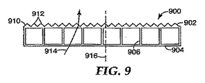
幾つかの実施形態では、第1の又は第2の層の表面は平坦であってよく、反射防止コーティングが施されてよい。他の実施形態では、第1の及び/又は第2の層は光学機能を発揮する場合がある。例えば、第1の及び/又は第2の層の外側又は内側表面にはマット仕上げが施されてよい。別の例示的な実施形態では、第1の及び第2の層にはなんらかの表面構造体が設けられてよい。例えば、図9に模式的に示されている溝付きプレート900は、連結部材906を介して共に取り付けられる第1の及び第2の層902、904を有する。この特別な実施形態では、第1の層902の上方表面910には一連のプリズム状リブ912が設けられている。このリブ912は互いに平行に置かれてよい、この場合、表面910はプリズム輝度向上層のような働きをして、一部の軸外(off-axis)光の方向を変えて、光線914により例示されるように、軸916に対してより平行な方向に伝播する。
In some embodiments, the surface of the first or second layer may be flat and may be provided with an anti-reflective coating. In other embodiments, the first and / or second layer may perform an optical function. For example, the outer or inner surface of the first and / or second layer may have a matte finish. In another exemplary embodiment, the first and second layers may be provided with some surface structure. For example, the
この溝付きプレートは、他の形式の表面を有してもよい。図10に模式的に示されている別の実施例において、溝付きプレート1000の第1の層1002はプレートを通過する光1014に光学パワーを提供する一連のレンズ1012を備える上方表面1010を有する。このレンズ1012は、連結部材1006間の間隔に等しい幅を有してよいが、有することを要求されない。このレンズ1012は、プレート1000の幅にわたって延伸するレンチキュラーレンズであってよい。このタイプのレンズは、押出成形プロセスを用いて作製されるプレートに特によく適している。レンズ1012を形成するために成型のような、他の方法が使用されてもよい。
The grooved plate may have other types of surfaces. In another embodiment, shown schematically in FIG. 10, the
溝付きプレートは、ディスプレーにおける他の光学層を支持するのに使用されてもよい。例えば、1つ以上の他の層が溝付きプレートに取り付けられてもよい。以下の実施例は、他の層と溝付きプレートとの幾つかの可能な組み合わせを例示するために提示される。図11Aは、溝付きプレートの上方層1102の上方表面に取り付けられる反射偏光子層1110を備えた溝付きプレート1101を有する光学層の配列体1100を示す。この反射偏光子層1110は、接着剤、例えば、透明接着剤又は光学拡散接着剤を用いて取り付けられてよい。プリズム状輝度向上層1112は、反射偏光子層1110の上に取り付けられてよい。幾つかの例示的な実施形態では、一部の光が、空気インターフェイス又は低から高屈折率へ移るインターフェイスを通って輝度向上層1112へ入射するのが望ましいことがある。したがって、低屈折率材料の層、例えば、フッ素化ポリマーは輝度向上層1112と輝度向上層1112の下の次の層との間に設置されてよい。
Grooved plates may be used to support other optical layers in the display. For example, one or more other layers may be attached to the fluted plate. The following examples are presented to illustrate some possible combinations of other layers and grooved plates. FIG. 11A shows an array of
他の例示的な実施形態では、空隙が輝度向上層1112と輝度向上層1112の下の層との間に設けられる場合がある。空隙を提供する1つの手法は、輝度向上層1112及び輝度向上層1112の下の層の対向面の一方又は両方の上に構造体を備えることである。例示された実施形態では、輝度向上層1112の下方表面1114は隣接層に接触する突出部1116と共に構造化される。空所1118は、したがって突出部1116間に形成され、その結果突出部1116間の位置において輝度向上層1112に入射する光が空気インターフェイスを通って入射する。他の実施形態では、反射偏光子層1110が省略され、プリズム型輝度向上層1112が溝付きプレート1101へ直接取り付けられることがある。幾つかの実施形態では、溝付き層1101は光学拡散をもたらし、又は単独の拡散層が設けられることがあり、例えば、(i)溝付き層と(ii)反射偏光子層1110及び/又はプリズム型輝度向上層1112との間で、溝付き層1101の下方層1104に取り付けられるか又は溝付き層1101の第1の層1102に取り付けられる。
In other exemplary embodiments, a void may be provided between the
空所を形成し、したがって輝度向上層に入射する光に対して空気インターフェイスを提供する他の手法が、使用されてもよい。例えば、輝度向上層は平坦な下方表面を有してもよく、隣接層が突出部と構造化される。これらの、及び追加の手法は、米国特許第7,010,212号(エモン(Emmons)ら)に記載される。本明細書に記載される溝付きプレートの実施形態のいずれもが、輝度向上層に入射する光のために空気インターフェイスを提供するように構成されてよい。 Other techniques for creating a void and thus providing an air interface for light incident on the brightness enhancement layer may be used. For example, the brightness enhancement layer may have a flat lower surface and the adjacent layer is structured with protrusions. These and additional techniques are described in US Pat. No. 7,010,212 (Emmons et al.). Any of the grooved plate embodiments described herein may be configured to provide an air interface for light incident on the brightness enhancement layer.
溝付きプレート1101に取り付けられるフィルムの順序は異なる場合がある。例えば、反射偏光子層1110は輝度向上層1112のプリズム状表面に取り付けられてよく、輝度向上層1112は溝付きプレート1101に取り付けられる。この配列体1120は、図11Bに模式的に示されている。光学フィルムの輝度向上層のプリズム状表面への取り付けについて、米国特許第6,846,089号(スチブンソン(Stevenson)ら)に詳細に記載されている。
The order of the films attached to the
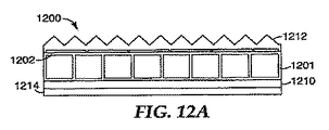
1枚以上のフィルムが、溝付きプレートの下方層に取り付けられている配列体1200を示す例示的な一実施形態が、図12Aに模式的に示されている。この実施形態では、反射偏光子1210が溝付きプレート1201の第2の層1204に取り付けられ、プリズム状輝度向上層1212が溝付きプレート1201の第1の層に取り付けられる。所望による拡散層1214は、反射偏光子1210の下方表面に取り付けられてよい。他の実施形態では、溝付きプレートそれ自身がある程度の拡散をもたらすことがある。このような場合には、溝付きプレート1201は反射偏光子1210を通過した光を有意には偏光解除しないことが所望されてよい。
An exemplary embodiment showing an
光管理フィルム配列体に取り付けられる溝付きプレート1201の別の例示的な実施形態1220が、図12Bに模式的に示されている。この実施形態1220では、拡散層1222が溝付きプレート1201に取り付けられる。中間層1224は、拡散層1222の上に配設され、そしてプリズム状輝度向上層1226が中間層1224の上に配設される。拡散層1222は、例えば、アクリル発泡体テープであってよく、この発泡体テープは中間層1224が発泡体テープ内へ押し込まれると変形し、中間層が置かれる凹部領域を作り出す。この中間層1224は、光学機能を有してもよく、例えば、中間層1224が反射偏光子フィルムであってもよい。溝付きプレートと共に使用されてもよい、他の好適な光管理フィルム配列体の実施例は、米国特許出願公開第2006/0082699号(ゲールセン(Gehlsen)ら)にさらに詳細に記載されている。
Another
成型に加えて、溝付きプレートを作製する他の方法がある。1つの方法が、既に適用されている連結部材を有する、スパイン(背骨)を別の光学フィルムに取り付けることである。この手法は、図13A及び13Bに模式的に示されている。このスパイン1302は、横断部材1304及び連結部材1306の配置を有する。この連結部材1306は、横断部材1304と一体化されてもよい。例えば、スパイン1302は成型又は押出成形によって形成されてよい。スパイン1302は、溝付きプレートについて前述したものと同一種類の材料で形成されてよい。こうして、スパイン1302は光学透明材料又は光学散乱材料で形成されてよい。
In addition to molding, there are other methods of making grooved plates. One way is to attach the spine (spine) to another optical film, with the connecting member already applied. This approach is schematically illustrated in FIGS. 13A and 13B. The
光学フィルム1310は、連結部材1306に取り付けられる。この光学フィルムは、任意の好適なタイプのフィルムであってよい。例えば、フィルム1310はプリズム状輝度向上フィルム、拡散フィルム、反射偏光子フィルム、ゲインディヒューザーフィルム、レンズフィルム、吸収偏光子、マットフィルムなどとしてよい。加えて、光学フィルム1310は単純に透明フィルムとしてよい。さらに、光学フィルムはまた、横断部材1304の下のスパイン1302に取り付けられてよい。
The
図13Bは、連結部材1306に取り付けられている光学フィルム1310を示している。このフィルム1310は、任意の好適な方法を用いて連結部材に取り付けられてよい。例えば、フィルム1310の下方表面1312及び/又は連結部材1306の先端部1314は、下方表面1312及び連結部材先端部1314が接触して定置された後に硬化される接着剤で塗布されてよい。フィルム1310及び連結部材1306が両方とも高分子材料で形成される、別の手法において、それぞれの高分子材料が完全に架橋される前にフィルム1310及び連結部材1306は接触して定置されてよく、フィルム1310及び連結部材1306がその後でまとめて架橋される。幾つかの他の手法が使用されてもよい、例えば、光学フィルムと溝との間にボンドを作り出すために押出成形の直後に光学フィルムを溶融ポリマーに接触させる。別の手法において、溝が加熱され(押出成形後)、後に積層されてよい。また、共押し出しされた溝も使用されてよく、これにより溝が基材(非接着剤、構造用部材)としてのある材料と、先端部の上で共押し出しされた別の材料(接着剤タイプの材料)で形成される。
FIG. 13B shows the
フィルム1310が取り付けられた後に、フィルム1310及びスパイン1302は溝1316を有するプレートを共に形成する。
After
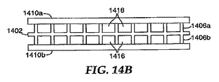
図14A(分離された要素)及び14B(共に取り付けられる要素)に模式的に示されている、別の実施形態では、スパイン1402が横断部材1404のそれぞれの側に連結部材1406a、1406bのセットを有する。2種の光学フィルム1410a、1410bは、連結部材1406a、1406bのそれぞれのセットに取り付けられてよい。この光学フィルム1406a、1406bは、透明フィルム、拡散フィルム、プリズム状輝度向上フィルム、反射偏光フィルムなどのような、任意の所望のタイプの光学フィルムであってよい。
In another embodiment, shown schematically in FIGS. 14A (separated elements) and 14B (elements attached together), the
フィルム1410a、1410bの少なくとも一方がスパイン1402に取り付けられた後に、フィルム1410a及び1410b及びスパイン1402は溝1416を有するプレートを共に形成する。
After at least one of
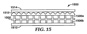
図14Bに示されるタイプのスパイン1502を備える光学フィルム配列体1500の特定の一実施形態が、図15に模式的に示されている。この実施形態では、拡散層1510が下方連結部材1506bに取り付けられており、プリズム状輝度向上層1512が上方連結部材に取り付けられている。反射偏光子層1514が、所望によりプリズム状輝度向上層1512の構造化される側に取り付けられてよい。
One particular embodiment of an
別の説明的な配列体1600が図16に模式的に示されており、ここでは、反射偏光子1514が拡散層1510とスパイン1502との間に配置されている。
Another
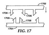
2つの層を共に取り付けるための別の手法は、相互連結可能である層を用いることである。例えば、この2つの層は、食品貯蔵バッグを封止するために使用されるもののような取り付け機構を用いて互いに機械的に取り付け可能としてよい。このような機構の例示的な実施形態は、図17に示されており、これは上方及び下方層1702、1704の部分を示している。各層1702、1704は相手層へ向けられている、それぞれの相互連結部材1706、1708を有する。2つの層1702、1704が、共に押しつけられたときに、相互連結部材1706、1708は共にロックして連結部材を形成する。これらの層1702、1704はそれぞれの相互連結部材1706、1708と共に、例えば、押出成形プロセスを用いて形成されてよい。この相互連結部材1706は、相互連結部材1708と同一の形状であってもよいが、そのようには要求されない。
Another approach for attaching the two layers together is to use layers that are interconnectable. For example, the two layers may be mechanically attachable to each other using an attachment mechanism such as that used to seal a food storage bag. An exemplary embodiment of such a mechanism is shown in FIG. 17, which shows portions of the upper and
上方及び下方層を連結するためにスパインが使用されるか否かにかかわらず、溝付きプレートは部分的に連続したプロセスにおいて形成されてよい。上方及び下方層を形成するフィルム及び所望によるスパインは、それぞれのロールから外され、共に取り付けられてよい。一旦これらの層が互いに取り付けられると、その結果得られる溝付き作製物は比較的に剛性である。個々のプレートは、連続溝付き作製物から切断されることができる。 Regardless of whether spines are used to connect the upper and lower layers, the fluted plate may be formed in a partially continuous process. The films forming the upper and lower layers and the optional spine may be removed from their respective rolls and attached together. Once these layers are attached to each other, the resulting grooved product is relatively rigid. Individual plates can be cut from the continuous fluted product.
溝付きプレートは、テレビジョンディスプレー又はモニターなどの、ディスプレーシステムにおいて熱管理を改善するために使用されてよい。図18に模式的に示されている、ディスプレーシステム1800の例示的な一実施形態が、1つ以上の光源1802と、溝付きプレート1804と、光管理層配列体1806と、ディスプレーパネル1808と、を備える。冷媒が、溝付きプレート1804の溝を通って流れてもよい、これは結果的にディスプレーシステムの低い運転温度をもたらす。この冷媒は空気であってもよい、そして、幾つかの実施形態では、空気は単純に自然対流に起因して垂直に向いた溝を通って流れてよい。他の実施形態では、冷媒は冷媒サーキュレータにより溝を通って押し込まれてよい。例えば、ファン1810は、空気を溝付きプレート1804の溝を通って押し込むために使用されてよい。他の実施形態では、水などの、透明流体がポンプによって溝を通って押し込まれてよい。
Grooved plates may be used to improve thermal management in display systems, such as television displays or monitors. One exemplary embodiment of a
異なる層が配列体の底部から最上部まで異なる順序で、又はスパインに対して異なる位置に現れる、本発明の範囲内に多数の異なる可能な配列体があることが理解されるであろう。 It will be understood that there are a number of different possible arrays within the scope of the present invention where the different layers appear in different orders from the bottom to the top of the array or at different positions relative to the spine.
本発明は、上に記載した特定の実施例に限られるとみなすべきではなく、添付の請求項で明確に提示されているとおり、本発明のあらゆる態様を網羅していると理解すべきである。本明細書を検討すれば、本発明を適用可能なさまざまな変更例、等価なプロセス、多数の構造が本発明に関連する当業者には容易に明らかになろう。例えば、自立型(フリースタンディング)光学フィルムはまた他の光学層と共に取り付けられる溝付きプレートと横に並んでディスプレーデバイス内で使用されてよい。また、ディスプレーは1つより多い溝付きプレートを使用してもよい。複数溝付きプレートの溝は互いに平行に配置されてよい、若しくは1つのプレートの溝は別の溝付きプレートの溝とは非平行に向いていてもよい。特許請求の範囲はこのような修正及び装置を網羅しようとするものである。 The present invention should not be considered limited to the particular embodiments described above, but should be understood to cover all aspects of the present invention as clearly set forth in the appended claims. . Upon review of this specification, various modifications, equivalent processes, and numerous structures to which the present invention can be applied will be readily apparent to those skilled in the art to which the present invention relates. For example, free-standing optical films may also be used in display devices side by side with a fluted plate that is attached with other optical layers. The display may also use more than one grooved plate. The grooves of the multi-grooved plate may be arranged parallel to each other, or the grooves of one plate may face non-parallel to the grooves of another grooved plate. The claims are intended to cover such modifications and devices.
本発明は、添付図面と関連して本発明の様々な実施形態の以下の発明を実施するための最良の形態を考慮してより完全に理解されると思われる。図面の中では同様な参照番号は同様な要素を示す。 The present invention will be more fully understood in view of the following best mode for carrying out the invention of various embodiments of the invention in conjunction with the accompanying drawings. In the drawings, like reference numbers indicate like elements.
本発明は様々な変更及び代替形状が可能であるが、その具体例を一例として図面に示すと共に詳細に説明する。しかしながら、本発明を、記載される特定の実施形態に限定することを意図しないことが理解されるべきである。反対に、添付の特許請求の範囲により規定されるように本発明の精神及び範囲内にあるすべての変更例、等価物及び代替物を網羅しようとするものである。 While the invention is susceptible to various modifications and alternative forms, specific examples thereof are shown by way of example in the drawings and will herein be described in detail. However, it should be understood that the invention is not intended to be limited to the particular embodiments described. On the contrary, the intention is to cover all modifications, equivalents, and alternatives falling within the spirit and scope of the invention as defined by the appended claims.
Claims (19)
第1の光管理層と、前記第1の光管理層とほぼ平行で、及び前記第1の光管理層から離隔している横断部材と、前記横断部材と一体となっていて、前記第1の光管理層に取り付けられる第1の連結部材の配列体と、を含む溝付き層を含む、光管理ユニット。 A light management unit for use between a display panel and a backlight, the light management unit having a side surface of the display panel for directing a direction toward the display panel and a side surface of the backlight facing the direction of the backlight. And the unit is
A first light management layer, a transverse member substantially parallel to the first light management layer and spaced apart from the first light management layer, and integral with the transverse member; A light management unit, comprising: a grooved layer including: an array of first coupling members attached to the light management layer.
ディスプレーパネルと、
前記光源と前記ディスプレーパネルとの間に配設された光管理層配列体であって、前記光源が前記光管理層配列体を通して前記ディスプレーパネルを照光し、前記光管理層配列体が溝付きプレートを含み、前記溝付きプレートが、前記ディスプレーパネルに面する前面層と、前記光源に面する背面層と、前記前面及び背面層を連結する複数の連結部材とを有する光管理層配列体と、を備えるディスプレーシステム。 A light source;
A display panel,
A light management layer array disposed between the light source and the display panel, wherein the light source illuminates the display panel through the light management layer array, and the light management layer array is a grooved plate. A light management layer array in which the grooved plate has a front layer facing the display panel, a back layer facing the light source, and a plurality of connecting members connecting the front and back layers; Display system with
Applications Claiming Priority (2)
| Application Number | Priority Date | Filing Date | Title |
|---|---|---|---|
| US11/276,442 US20070203267A1 (en) | 2006-02-28 | 2006-02-28 | Optical display with fluted optical plate |
| PCT/US2007/004867 WO2007100742A1 (en) | 2006-02-28 | 2007-02-23 | Optical display with fluted optical plate |
Publications (2)
| Publication Number | Publication Date |
|---|---|
| JP2009528571A true JP2009528571A (en) | 2009-08-06 |
| JP2009528571A5 JP2009528571A5 (en) | 2010-04-08 |
Family
ID=38444883
Family Applications (1)
| Application Number | Title | Priority Date | Filing Date |
|---|---|---|---|
| JP2008557320A Withdrawn JP2009528571A (en) | 2006-02-28 | 2007-02-23 | Optical display with grooved optical plate |
Country Status (7)
| Country | Link |
|---|---|
| US (1) | US20070203267A1 (en) |
| JP (1) | JP2009528571A (en) |
| KR (1) | KR20080109732A (en) |
| CN (1) | CN101390002A (en) |
| DE (1) | DE112007000458T5 (en) |
| TW (1) | TW200741309A (en) |
| WO (1) | WO2007100742A1 (en) |
Cited By (2)
| Publication number | Priority date | Publication date | Assignee | Title |
|---|---|---|---|---|
| JP2013532848A (en) * | 2010-07-28 | 2013-08-19 | アンデルス・レンスモ | Optical panel and method for manufacturing the optical panel |
| US10684508B2 (en) | 2017-12-06 | 2020-06-16 | Lg Display Co., Ltd. | Backlight unit and display device including the same |
Families Citing this family (12)
| Publication number | Priority date | Publication date | Assignee | Title |
|---|---|---|---|---|
| KR100719658B1 (en) * | 2005-11-17 | 2007-05-17 | 삼성에스디아이 주식회사 | Portable display device |
| CN101408628A (en) * | 2007-10-10 | 2009-04-15 | 群康科技(深圳)有限公司 | Diffusion chip and manufacturing process thereof and backlight module unit and LCD device |
| US8425662B2 (en) | 2010-04-02 | 2013-04-23 | Battelle Memorial Institute | Methods for associating or dissociating guest materials with a metal organic framework, systems for associating or dissociating guest materials within a series of metal organic frameworks, and gas separation assemblies |
| DK2823216T3 (en) * | 2012-03-05 | 2022-06-07 | Lmpg Inc | LIGHT EMITTING PANEL DEVICES AND LIGHT CONDUCTORS THEREOF |
| CN113917585A (en) | 2014-10-23 | 2022-01-11 | 康宁股份有限公司 | Light diffusion member and method of manufacturing light diffusion member |
| JP6274079B2 (en) * | 2014-11-04 | 2018-02-07 | 日本軽金属株式会社 | Pellicle support frame and manufacturing method |
| WO2017024265A1 (en) * | 2015-08-05 | 2017-02-09 | 3M Innovative Properties Company | Optical diffusing film laminate and method of making |
| US10480752B2 (en) | 2016-02-27 | 2019-11-19 | Svv Technology Innovations, Inc. | Structurally reinforced illumination panels and a method of making the same |
| EP3669042A1 (en) * | 2017-10-12 | 2020-06-24 | Apple Inc. | Light transmitting panel with active components |
| KR102519932B1 (en) * | 2017-10-19 | 2023-04-11 | 삼성전자주식회사 | Display apparatus |
| CN110095929A (en) * | 2018-01-29 | 2019-08-06 | 精工爱普生株式会社 | Projector |
| US20220350063A1 (en) * | 2021-04-29 | 2022-11-03 | Meta Platforms Technologies, Llc | High surface quality optical film |
Family Cites Families (63)
| Publication number | Priority date | Publication date | Assignee | Title |
|---|---|---|---|---|
| US2841904A (en) * | 1957-01-29 | 1958-07-08 | Theodore M Jablon | Slide mountings |
| US3655263A (en) * | 1970-04-20 | 1972-04-11 | Mark Hoffman | Light diffusion device |
| US4415509A (en) * | 1981-07-07 | 1983-11-15 | Mitsubishi Rayon Company, Ltd. | Acrylic laminated diffuser panel having high light-diffusing property and process for preparing same |
| US4830899A (en) * | 1986-07-04 | 1989-05-16 | Nissen Chemical Industry Co., Ltd. | Light reflection material, its manufacture and application |
| US4904079A (en) * | 1986-08-13 | 1990-02-27 | Sharp Kabushiki Kaisha | Liquid crystal display device for overhead projector |
| US5379139A (en) * | 1986-08-20 | 1995-01-03 | Semiconductor Energy Laboratory Co., Ltd. | Liquid crystal device and method for manufacturing same with spacers formed by photolithography |
| JPS6363020A (en) * | 1986-09-04 | 1988-03-19 | Semiconductor Energy Lab Co Ltd | Preparation of liquid crystal electro-optic device |
| JPS63118718A (en) * | 1986-11-07 | 1988-05-23 | Toyota Motor Corp | Production of liquid crystal display element |
| US5112722A (en) * | 1989-04-12 | 1992-05-12 | Nippon Sheet Glass Co., Ltd. | Method of producing light control plate which induces scattering of light at different angles |
| US6153289A (en) * | 1992-04-29 | 2000-11-28 | Murray; Nicholas J. | Laminates |
| TW289095B (en) * | 1993-01-11 | 1996-10-21 | ||
| US5428468A (en) * | 1993-11-05 | 1995-06-27 | Alliedsignal Inc. | Illumination system employing an array of microprisms |
| US5396350A (en) * | 1993-11-05 | 1995-03-07 | Alliedsignal Inc. | Backlighting apparatus employing an array of microprisms |
| US5882774A (en) * | 1993-12-21 | 1999-03-16 | Minnesota Mining And Manufacturing Company | Optical film |
| US5751388A (en) * | 1995-04-07 | 1998-05-12 | Honeywell Inc. | High efficiency polarized display |
| KR100407101B1 (en) * | 1995-10-12 | 2004-02-18 | 인터내셔널 비지네스 머신즈 코포레이션 | Light-transmitting material, planar light source device and liquid crystal display device |
| EP0802446B1 (en) * | 1995-11-06 | 2003-06-11 | Seiko Epson Corporation | Illuminator, liquid crystal display using the illuminator and electronic device |
| US6104454A (en) * | 1995-11-22 | 2000-08-15 | Hitachi, Ltd | Liquid crystal display |
| US5867316A (en) * | 1996-02-29 | 1999-02-02 | Minnesota Mining And Manufacturing Company | Multilayer film having a continuous and disperse phase |
| US5825543A (en) * | 1996-02-29 | 1998-10-20 | Minnesota Mining And Manufacturing Company | Diffusely reflecting polarizing element including a first birefringent phase and a second phase |
| JP3669541B2 (en) * | 1997-06-12 | 2005-07-06 | 株式会社エンプラス | Sidelight type surface light source device |
| US6497946B1 (en) * | 1997-10-24 | 2002-12-24 | 3M Innovative Properties Company | Diffuse reflective articles |
| US6343865B1 (en) * | 1998-02-17 | 2002-02-05 | Dai Nippon Printing Co., Ltd. | Non-glare film, polarizing device and display device |
| US6282821B1 (en) * | 1998-06-25 | 2001-09-04 | 3M Innovative Properties Company | Low-loss face diffuser films for backlit signage and methods for using same |
| US6352759B2 (en) * | 1998-08-20 | 2002-03-05 | Physical Optics Corporation | Non-lambertian glass diffuser and method of making |
| US6160663A (en) * | 1998-10-01 | 2000-12-12 | 3M Innovative Properties Company | Film confined to a frame having relative anisotropic expansion characteristics |
| US6827456B2 (en) * | 1999-02-23 | 2004-12-07 | Solid State Opto Limited | Transreflectors, transreflector systems and displays and methods of making transreflectors |
| KR20000060073A (en) * | 1999-03-11 | 2000-10-16 | 구본준 | Backlight of a liquid crystal display device |
| CN1181359C (en) * | 1999-03-31 | 2004-12-22 | 大赛璐化学工业株式会社 | Light scattering sheet, light scattering composite sheet, and liquid crystal display |
| JP3594868B2 (en) * | 1999-04-26 | 2004-12-02 | 日東電工株式会社 | Laminated polarizing plate and liquid crystal display |
| US6122103A (en) * | 1999-06-22 | 2000-09-19 | Moxtech | Broadband wire grid polarizer for the visible spectrum |
| KR100673796B1 (en) * | 1999-09-09 | 2007-01-24 | 키모토 컴파니 리미티드 | Transparent hard coat film |
| JP3882428B2 (en) * | 1999-10-29 | 2007-02-14 | セイコーエプソン株式会社 | Manufacturing method of liquid crystal device |
| KR100717092B1 (en) * | 2000-02-10 | 2007-05-10 | 데이진 가부시키가이샤 | Polyester film composite, light diffuser plate, and utilization thereof |
| WO2001079340A1 (en) * | 2000-04-13 | 2001-10-25 | 3M Innovative Properties Company | Light stable articles |
| US6917399B2 (en) * | 2001-02-22 | 2005-07-12 | 3M Innovative Properties Company | Optical bodies containing cholesteric liquid crystal material and methods of manufacture |
| US7173677B2 (en) * | 2001-04-12 | 2007-02-06 | Rohm Co., Ltd. | Back light unit for liquid crystal display device and method for manufacturing the unit |
| US6642974B2 (en) * | 2001-05-29 | 2003-11-04 | Chun-Chi Liao | Assembly of backlight mask |
| US6642977B2 (en) * | 2001-06-20 | 2003-11-04 | 3M Innovative Properties Company | Liquid crystal displays with repositionable front polarizers |
| JP3850241B2 (en) * | 2001-07-19 | 2006-11-29 | シャープ株式会社 | LIGHTING DEVICE AND LIQUID CRYSTAL DISPLAY DEVICE USING THE SAME |
| TWI293704B (en) * | 2002-02-19 | 2008-02-21 | Au Optronics Corp | |
| US6636363B2 (en) * | 2002-03-11 | 2003-10-21 | Eastman Kodak Company | Bulk complex polymer lens light diffuser |
| US7010212B2 (en) * | 2002-05-28 | 2006-03-07 | 3M Innovative Properties Company | Multifunctional optical assembly |
| JP3952168B2 (en) * | 2002-06-11 | 2007-08-01 | 富士通株式会社 | Electronic device, liquid crystal display device and light guide plate |
| KR20040009902A (en) * | 2002-07-26 | 2004-01-31 | 삼성전자주식회사 | Back light assembly using the same and liquid crystal display device |
| KR100878206B1 (en) * | 2002-08-13 | 2009-01-13 | 삼성전자주식회사 | Optical sheet and back light assembly using the same and liquid crystal display device using the same |
| US6842204B1 (en) * | 2002-09-06 | 2005-01-11 | Rockwell Collins | Color display system for NVIS Class A compatibility |
| DE10245580B4 (en) * | 2002-09-27 | 2006-06-01 | Siemens Ag | Device for generating an image |
| US7236217B2 (en) * | 2003-01-16 | 2007-06-26 | 3M Innovative Properties Company | Package of optical films with zero-gap bond outside viewing area |
| CN101441292A (en) * | 2003-02-28 | 2009-05-27 | 夏普株式会社 | Surface radiating conversion element, an LCD and a method for fabricating the surface radiating conversion element |
| KR20040090667A (en) * | 2003-04-18 | 2004-10-26 | 삼성전기주식회사 | light unit for displaying |
| US7041365B2 (en) * | 2003-05-12 | 2006-05-09 | 3M Innovative Properties Company | Static dissipative optical construction |
| US6846089B2 (en) * | 2003-05-16 | 2005-01-25 | 3M Innovative Properties Company | Method for stacking surface structured optical films |
| JP2005044744A (en) * | 2003-07-25 | 2005-02-17 | Clariant Internatl Ltd | Surface light source device |
| US7413336B2 (en) * | 2003-08-29 | 2008-08-19 | 3M Innovative Properties Company | Adhesive stacking for multiple optical films |
| TWM254613U (en) * | 2003-11-14 | 2005-01-01 | Litemax Electronics Inc | Backlight module of liquid crystal display |
| US20050184970A1 (en) * | 2003-12-15 | 2005-08-25 | Schott Corporation | Touch control attachment |
| TWI272421B (en) * | 2004-05-13 | 2007-02-01 | Au Optronics Corp | Backlight unit and liquid crystal display utilizing the same |
| JP4305850B2 (en) * | 2004-05-24 | 2009-07-29 | 株式会社 日立ディスプレイズ | Backlight device and display device |
| US7165856B2 (en) * | 2005-02-22 | 2007-01-23 | Chunghwa Picture Tubes, Ltd. | Light-duide plate and backlight module |
| KR20060105346A (en) * | 2005-04-04 | 2006-10-11 | 삼성전자주식회사 | Back light unit and liquid crystal display apparatus employing the same |
| US7766531B2 (en) * | 2006-03-29 | 2010-08-03 | 3M Innovative Properties Company | Edge-lit optical display with fluted optical plate |
| US20070236413A1 (en) * | 2006-03-29 | 2007-10-11 | 3M Innovative Properties Company | Fluted optical plate with internal light sources and systems using same |
-
2006
- 2006-02-28 US US11/276,442 patent/US20070203267A1/en not_active Abandoned
-
2007
- 2007-02-23 WO PCT/US2007/004867 patent/WO2007100742A1/en active Application Filing
- 2007-02-23 DE DE112007000458T patent/DE112007000458T5/en not_active Withdrawn
- 2007-02-23 CN CNA2007800061516A patent/CN101390002A/en active Pending
- 2007-02-23 KR KR1020087020626A patent/KR20080109732A/en not_active Application Discontinuation
- 2007-02-23 JP JP2008557320A patent/JP2009528571A/en not_active Withdrawn
- 2007-02-27 TW TW096106734A patent/TW200741309A/en unknown
Cited By (3)
| Publication number | Priority date | Publication date | Assignee | Title |
|---|---|---|---|---|
| JP2013532848A (en) * | 2010-07-28 | 2013-08-19 | アンデルス・レンスモ | Optical panel and method for manufacturing the optical panel |
| US9478154B2 (en) | 2010-07-28 | 2016-10-25 | Anders Rensmo | Light panel and method for producing the light panel |
| US10684508B2 (en) | 2017-12-06 | 2020-06-16 | Lg Display Co., Ltd. | Backlight unit and display device including the same |
Also Published As
| Publication number | Publication date |
|---|---|
| WO2007100742A1 (en) | 2007-09-07 |
| DE112007000458T5 (en) | 2009-01-22 |
| TW200741309A (en) | 2007-11-01 |
| CN101390002A (en) | 2009-03-18 |
| KR20080109732A (en) | 2008-12-17 |
| US20070203267A1 (en) | 2007-08-30 |
Similar Documents
| Publication | Publication Date | Title |
|---|---|---|
| JP2009528571A (en) | Optical display with grooved optical plate | |
| US7766531B2 (en) | Edge-lit optical display with fluted optical plate | |
| EP2023166B1 (en) | Optical Element Comprising Restrained Asymmetrical Diffuser | |
| US7777832B2 (en) | Multi-function enhancement film | |
| US20070236413A1 (en) | Fluted optical plate with internal light sources and systems using same | |
| US7320538B2 (en) | Optical film having a structured surface with concave pyramid-shaped structures | |
| JP5475232B2 (en) | Composite diffuser plates and direct illumination liquid crystal displays using them | |
| US7278775B2 (en) | Enhanced LCD backlight | |
| US7220026B2 (en) | Optical film having a structured surface with offset prismatic structures | |
| US20090201441A1 (en) | Tensioned optical element having crimping frame and spring | |
| US20080192352A1 (en) | Optical diffuser film and light assembly | |
| US7583881B2 (en) | Optical element and display with transparent tensioned supporting films | |
| JP2008541195A (en) | Backlit display device with uniform illumination | |
| JP2010510545A (en) | Backlight display with improved illuminance uniformity | |
| KR20100037117A (en) | A backlight assemblies having a transmissive optical film | |
| CN101251679A (en) | Optical device with self-supporting film assembly | |
| JP2010032868A (en) | Lens sheet, display optical sheet, and illumination device, electronic signboard, back light unit and display all using this optical sheet |
Legal Events
| Date | Code | Title | Description |
|---|---|---|---|
| A521 | Written amendment |
Free format text: JAPANESE INTERMEDIATE CODE: A523 Effective date: 20100219 |
|
| A621 | Written request for application examination |
Free format text: JAPANESE INTERMEDIATE CODE: A621 Effective date: 20100219 |
|
| A761 | Written withdrawal of application |
Free format text: JAPANESE INTERMEDIATE CODE: A761 Effective date: 20110603 |