JP2008541195A - Backlit display device with uniform illumination - Google Patents
Backlit display device with uniform illumination Download PDFInfo
- Publication number
- JP2008541195A JP2008541195A JP2008512368A JP2008512368A JP2008541195A JP 2008541195 A JP2008541195 A JP 2008541195A JP 2008512368 A JP2008512368 A JP 2008512368A JP 2008512368 A JP2008512368 A JP 2008512368A JP 2008541195 A JP2008541195 A JP 2008541195A
- Authority
- JP
- Japan
- Prior art keywords
- light
- diffusion layer
- layer
- display panel
- illumination light
- Prior art date
- Legal status (The legal status is an assumption and is not a legal conclusion. Google has not performed a legal analysis and makes no representation as to the accuracy of the status listed.)
- Withdrawn
Links
Images


Classifications
-
- G—PHYSICS
- G02—OPTICS
- G02B—OPTICAL ELEMENTS, SYSTEMS OR APPARATUS
- G02B5/00—Optical elements other than lenses
- G02B5/04—Prisms
- G02B5/045—Prism arrays
-
- G—PHYSICS
- G02—OPTICS
- G02F—OPTICAL DEVICES OR ARRANGEMENTS FOR THE CONTROL OF LIGHT BY MODIFICATION OF THE OPTICAL PROPERTIES OF THE MEDIA OF THE ELEMENTS INVOLVED THEREIN; NON-LINEAR OPTICS; FREQUENCY-CHANGING OF LIGHT; OPTICAL LOGIC ELEMENTS; OPTICAL ANALOGUE/DIGITAL CONVERTERS
- G02F1/00—Devices or arrangements for the control of the intensity, colour, phase, polarisation or direction of light arriving from an independent light source, e.g. switching, gating or modulating; Non-linear optics
- G02F1/01—Devices or arrangements for the control of the intensity, colour, phase, polarisation or direction of light arriving from an independent light source, e.g. switching, gating or modulating; Non-linear optics for the control of the intensity, phase, polarisation or colour
- G02F1/13—Devices or arrangements for the control of the intensity, colour, phase, polarisation or direction of light arriving from an independent light source, e.g. switching, gating or modulating; Non-linear optics for the control of the intensity, phase, polarisation or colour based on liquid crystals, e.g. single liquid crystal display cells
- G02F1/133—Constructional arrangements; Operation of liquid crystal cells; Circuit arrangements
- G02F1/1333—Constructional arrangements; Manufacturing methods
- G02F1/1335—Structural association of cells with optical devices, e.g. polarisers or reflectors
- G02F1/1336—Illuminating devices
- G02F1/133602—Direct backlight
- G02F1/133606—Direct backlight including a specially adapted diffusing, scattering or light controlling members
- G02F1/133607—Direct backlight including a specially adapted diffusing, scattering or light controlling members the light controlling member including light directing or refracting elements, e.g. prisms or lenses
-
- G—PHYSICS
- G02—OPTICS
- G02F—OPTICAL DEVICES OR ARRANGEMENTS FOR THE CONTROL OF LIGHT BY MODIFICATION OF THE OPTICAL PROPERTIES OF THE MEDIA OF THE ELEMENTS INVOLVED THEREIN; NON-LINEAR OPTICS; FREQUENCY-CHANGING OF LIGHT; OPTICAL LOGIC ELEMENTS; OPTICAL ANALOGUE/DIGITAL CONVERTERS
- G02F1/00—Devices or arrangements for the control of the intensity, colour, phase, polarisation or direction of light arriving from an independent light source, e.g. switching, gating or modulating; Non-linear optics
- G02F1/01—Devices or arrangements for the control of the intensity, colour, phase, polarisation or direction of light arriving from an independent light source, e.g. switching, gating or modulating; Non-linear optics for the control of the intensity, phase, polarisation or colour
- G02F1/13—Devices or arrangements for the control of the intensity, colour, phase, polarisation or direction of light arriving from an independent light source, e.g. switching, gating or modulating; Non-linear optics for the control of the intensity, phase, polarisation or colour based on liquid crystals, e.g. single liquid crystal display cells
- G02F1/133—Constructional arrangements; Operation of liquid crystal cells; Circuit arrangements
- G02F1/1333—Constructional arrangements; Manufacturing methods
- G02F1/1335—Structural association of cells with optical devices, e.g. polarisers or reflectors
- G02F1/1336—Illuminating devices
- G02F1/133602—Direct backlight
- G02F1/133611—Direct backlight including means for improving the brightness uniformity
Abstract
直接照明された表示装置は、表示パネルを照明するための照明光を生成する1以上の光源を含む光源装置を有する。拡散層が光源装置と表示パネルとの間に配置される。少なくとも1つの第1の輝度上昇層および反射型偏向子が、拡散層と表示パネルとの間に配置される。光変向面が拡散層と光源装置の間に配置される。光変向面は、光源装置から拡散層へ進む照射光の少なくとも一部の伝搬方向を変向する。 The directly illuminated display device includes a light source device that includes one or more light sources that generate illumination light for illuminating the display panel. A diffusion layer is disposed between the light source device and the display panel. At least one first brightness enhancement layer and a reflective deflector are disposed between the diffusion layer and the display panel. A light redirecting surface is disposed between the diffusion layer and the light source device. The light turning surface changes the propagation direction of at least part of the irradiation light traveling from the light source device to the diffusion layer.
Description
本発明は光学表示に関し、より詳細には、LCDモニタおよびLCDテレビジョンで使用され得るような、背後から光源で直接照明される液晶表示装置(LCDs)に関する。 The present invention relates to optical displays, and more particularly to liquid crystal displays (LCDs) that are directly illuminated with a light source from behind, such as may be used in LCD monitors and LCD televisions.
表示システムの中には、例えば液晶表示装置(LCDs)は、背後から照明されるものが若干ある。このような表示システムには、ラップトップコンピュータ、ハンドヘルド計算器、デジタル腕時計、テレビ等のような多くの装置において広い用途がある。一部のバックライト表示装置には、表示部の側面に配置された光源と、光源から表示パネルの背後に光を導くように配置された光導波路を含むものもある。例えばLCDモニタおよびLCDテレビジョンの他のバックライト表示部は、表示パネルの背後に配置された多数の光源を使用して背後から直接照明される。このような後者の配置は大型表示装置の普及と共にますます一般化しているが、その理由として一定水準の表示輝度を実現し、かつ表示サイズの2乗で増加する必要がある光出力に対して、後者の配置は表示装置の側面に沿って光源を設置するための利用可能な設置面積が表示サイズの増加に伴い一次関数的に増加するだけである。さらに、LCD−TVsのような一部の表示装置の用途では、表示部は他用途よりも長い距離から鑑賞するために十分な輝度を必要とする。さらに、LCD−TVで必要な視界角度は、LCDモニタおよびハンドヘルド型装置用のものと概ね異なる。 In some display systems, for example, some liquid crystal display devices (LCDs) are illuminated from behind. Such display systems have wide application in many devices such as laptop computers, handheld calculators, digital watches, televisions and the like. Some backlight display devices include a light source disposed on the side surface of the display unit and an optical waveguide disposed to guide light from the light source to the back of the display panel. For example, other backlight displays of LCD monitors and LCD televisions are illuminated directly from behind using a number of light sources arranged behind the display panel. This latter arrangement is becoming more and more common with the widespread use of large display devices. The reason for this is that it achieves a certain level of display luminance, and it is necessary for light output that needs to be increased by the square of the display size. In the latter arrangement, the available installation area for installing the light source along the side surface of the display device only increases linearly as the display size increases. Further, in some applications of display devices such as LCD-TVs, the display unit needs to have sufficient luminance for viewing from a longer distance than other applications. In addition, the viewing angle required for LCD-TV is generally different from that for LCD monitors and handheld devices.
LCDモニタおよび通常のLCD−TVは、多数の冷陰極蛍光ランプ(CCFLs)によって通常背後から照明される。このような光源は、直線的でありディスプレイの全幅に渡って伸び、その結果、表示部の背面は、暗い領域で分離された一筋の明るい縞によって照明される。このような照明プロフィールは望ましいものではなく、LCD装置の背面における照明プロフィールを滑らかにするために拡散プレートが通常使用される。 LCD monitors and normal LCD-TVs are usually illuminated from behind by a number of cold cathode fluorescent lamps (CCFLs). Such a light source is linear and extends across the entire width of the display, so that the back of the display is illuminated by a single bright stripe separated by dark areas. Such an illumination profile is not desirable and a diffuser plate is usually used to smooth the illumination profile at the back of the LCD device.
現状では、LCD−TV拡散プレートには、ガラス、ポリスチレンビーズ、およびCaCO3粒子を含むさまざまな分散相を有するポリメチルメタクリレート(PMMA)の高分子マトリックスが採用されている。このようなプレートは、ランプの高温に晒された後、しばしば変形するかまたは歪む。さらに、拡散プレートの中には、空間的にその幅を変更してLCDパネルの裏面における照明プロフィールをより均一にしようとする拡散特性を備えるものもある。このような非均一拡散体は、プリントパターン拡散体と呼ばれることもある。これらは、組み立ての時点で拡散パターンが照明源に対して合わされなければならないので、製造が高価であり製造コストを増加させる。さらに、拡散プレートは、拡散粒子を高分子マトリックス全体で均一に分散させるためカスタマイズした押し出し配合が必要とされ、これがさらにコストを増大させる。 Currently, LCD-TV diffuser plates employ polymer matrices of polymethyl methacrylate (PMMA) with various dispersed phases including glass, polystyrene beads, and CaCO 3 particles. Such plates often deform or distort after exposure to the high temperature of the lamp. In addition, some diffusion plates have diffusion characteristics that attempt to make the illumination profile more uniform on the back side of the LCD panel by spatially changing its width. Such non-uniform diffusers are sometimes called print pattern diffusers. These are expensive to manufacture and increase manufacturing costs because the diffuse pattern must be matched to the illumination source at the time of assembly. In addition, the diffusion plate requires a customized extrusion formulation to disperse the diffusing particles uniformly throughout the polymer matrix, which further increases cost.
本発明の実施形態は、照明光を生成することができる1以上の実施形態光源を備える光源装置および表示パネルを有する直接照明された表示装置を目的とする。拡散層は、光源装置と表示パネルとの間に配置される。少なくとも1つの第1の輝度上昇層および反射型偏光子が、拡散層および表示パネルの間に配置される。光変向面が、拡散層および光源装置の間に配置される。光変向面は、光源から拡散層へ進む照明光の少なくとも一部の伝搬方向を変化させる。 Embodiments of the present invention are directed to a directly illuminated display device having a light source device and a display panel comprising one or more embodiment light sources capable of generating illumination light. The diffusion layer is disposed between the light source device and the display panel. At least one first brightness enhancement layer and a reflective polarizer are disposed between the diffusion layer and the display panel. A light turning surface is disposed between the diffusion layer and the light source device. The light redirecting surface changes the propagation direction of at least part of the illumination light traveling from the light source to the diffusion layer.
本発明の別の実施形態は、表示パネルの動作方法に関する。方法は、照明光を生成する工程および照明光をほぼ表示パネルの方に方向づける工程を含む。照明光は、第1の構造面において変向される。変向された照明光は、拡散された後表示ディスプレイパネルへと進む。 Another embodiment of the present invention relates to a method for operating a display panel. The method includes generating illumination light and directing the illumination light substantially toward the display panel. The illumination light is redirected at the first structural surface. The diverted illumination light travels to the display panel after being diffused.
本発明の上記の概要は、本発明の各図示の実施形態またはすべての実施を説明しようとするものではない。図および以下の詳細な説明がこのような実施形態をより具体的に例示する。 The above summary of the present invention is not intended to describe each illustrated embodiment or every implementation of the present invention. The figures and the following detailed description illustrate such embodiments more specifically.
本発明は、液晶表示装置(LCDsまたはLCディスプレイ)のような表示パネルに適用可能であり、例えばLCDモニタおよびLCDテレビジョン(LCD−TVs)で使用されるような、背後から直接照明されるLCDに特に適用可能である。さらに詳細には、本発明は、LCディスプレイを照明する直接照明バックライトによって生じた光の管理を目的とする。光管理フィルムの配列は、バックライトと表示パネル自体の間に通常配置される。共に積層されるか自立しているかであり得る光管理フィルムの配列には、拡散板、およびプリズム構造面を有する輝度上昇フィルムが通常含まれる。 The present invention is applicable to display panels such as liquid crystal display devices (LCDs or LC displays), such as LCDs that are illuminated directly from behind, such as those used in LCD monitors and LCD televisions (LCD-TVs). It is particularly applicable to. More particularly, the present invention is directed to managing the light produced by a direct illumination backlight that illuminates an LC display. An array of light management films is usually placed between the backlight and the display panel itself. An array of light management films that can be laminated together or self-supporting usually includes a diffuser plate and a brightness enhancement film having a prismatic structure surface.
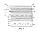
直接照明表示装置100の代表的実施形態の外部断面図を図1に示す。このような表示装置100は、例えばLCDモニタまたはLCD−TVにおいて使用され得る。表示装置100は、LCパネル102の使用を基にすることができ、パネルプレート106の間に配置されたLC104の層を通常有する。プレート106は、しばしばガラスで形成され、LC層104中の液晶の配向を制御するよう内面に電極構造および整列層を含むことができる。電極構造は、LCパネル画素を規定し、液晶の配向が隣接する領域から独立して制御されることが可能であるLC層の領域を画定するように通常配列される。表示画像に着色するため、1以上のプレート106にカラーフィルターが含まれることも可能である。
An external cross-sectional view of a representative embodiment of a direct
上部吸収偏光子108がLC層104の上に配置され、下部吸収偏光子110がLC層104の下に配置される。図示の実施形態において、上部吸収偏光子および下部吸収偏光子は、LCパネル102の外側に配置される。吸収偏光子108、110、およびLCパネル102は、組み合わされてバックライト112から表示装置100を介して視聴者に達する光の透過を制御する。例えば吸収偏光子108、110は、その透過軸を垂直にして配置されることが可能である。非活性状態においては、LC層104の画素は通過する光の偏光を変えることができない。従って、下部吸収偏光子110を通過する光は上部吸収偏光子108によって吸収される。これに対して画素が活性化されているときは、通過する光が偏光されると回転するので、下部吸収偏光子110を透過する光の少なくとも一部は上部吸収偏光子108も透過する。LC層104の異なる画素を例えばコントローラ114によって選択的に活性化することで、特定の所望の場所で表示装置から光が透過して画像が形成され視聴者が見られるようになる。コントローラには、例えばコンピュータ、またはテレビジョン画像を受信して表示するテレビジョンコントローラが含まれることが可能である。1以上の追加層109が上部吸収偏光子108を覆って提供されて、例えば機械的および/または環境的保護を表示面に提供することができる。1つの代表的実施形態において、層109には吸収偏光子108を覆うハードコートが含まれることが可能である。
An upper absorbing
LCディスプレイのタイプによっては上記とは異なる態様で動作し得るということが理解されるべきである。例えば、吸収偏光子は平行に整列されることが可能であり、LCパネルは非活性状態において光の偏光を回転させることができる。そのような場合であっても、このような表示装置の基本的な構造は上記のものと類似している。 It should be understood that some types of LC displays may operate differently than described above. For example, the absorbing polarizer can be aligned in parallel and the LC panel can rotate the polarization of light in the inactive state. Even in such a case, the basic structure of such a display device is similar to that described above.
バックライト112には、LCパネル102を照明する光を生成する多数の光源116が含まれる。LCD−TVまたはLCDモニタに使用される光源116は、たいていの場合、表示装置100の高さに沿って延びる直線状の冷陰極蛍光管である。しかし、フィラメントランプまたはアークランプ、発光ダイオード(LEDs)、平坦蛍光パネル(flat fluorescent panels)、または外部蛍光ランプのような他のタイプの光源が使用されることが可能である。このような光源のリストは、限定または完全を期すものではなく例示のみを意図している。
The backlight 112 includes a number of
バックライト112は、光源116から下に伝搬する光をLCパネル102から離れる方向に反射するための反射板118も含む。反射板118は、以下の説明のように表示装置100内部で光を再利用するために有用でもある。反射板118は、鏡面反射板であってもまたは拡散反射板であってもよい。反射板118として使用され得る鏡面反射板の一例は、ミネソタ州セントポール(St. Paul)3M社から入手可能なビキュイティ(Vikuiti(商標))高鏡面反射(Enhanced Specular Reflection (ESR))フィルムである。好適な拡散反射板の例には、二酸化チタン、硫酸バリウム、炭酸カルシウム等のような反射粒子が広く装填されたPET、PC、PP、PSのようなポリマーが含まれる。拡散反射板の他の例には、ミクロ孔質材および小繊維含有材(fibril-containing materials)が含まれ、これらは共有の米国特許第5,976,686号に記載されている。
The backlight 112 also includes a
光管理フィルムの配列120は、光管理装置とも呼ばれるが、バックライト112とLCパネル102の間に配置される。光管理フィルムは、バックライト112からの光の伝搬に影響し、表示装置100の動作を改善する。例えば、光管理フィルムの配列120には、拡散板122が含まれることが可能である。拡散板122は、光源から受けた光を拡散するために使用され、それによりLCパネル102に入射する照明光の均一性を増すこととなる。その結果、視聴者が認識する画像はさらに均一に明るいものとなる。
The light
光管理装置120は、反射型偏光子124を含むこともできる。光源116は、偏光していない光を通常生成するが、下部吸収偏光子110は単一の偏光状態の光のみを伝搬するので、光源116で生成された光の約半分がLC層104へ伝搬されない。しかし、光を反射するための反射型偏光子124が使用されることが可能であり、別な方法では下部吸収偏光子で吸収されるであろう光を反射する。従って、反射型偏光子124と反射体118間の反射によってこの光は再利用されることが可能である。反射型偏光子124によって反射された光の少なくとも一部は、偏光解消されることが可能であり、その後偏光状態で反射型偏光子124に戻り、反射型偏光子124および下部吸収偏光子110を介してLC層104に伝搬される。このようにして、反射型偏光子124は、光源116の発した光がLC層104に到達する割合を増加するように使用されることが可能であり、それにより表示装置100によって生成された画像をより明るくする。
The
任意の好適なタイプの反射型偏光子、例えば、多層光学フィルム(MOF:multilayer optical film)反射型偏光子、連続/分散相偏光子(continuous/disperse phase polarizers)、ワイヤグリッド反射型偏光子、またはコレステリック反射型偏光子のような拡散反射型偏光フィルム(DRPF:diffusely reflective polarizing film)を使用することができる。 Any suitable type of reflective polarizer, such as a multilayer optical film (MOF) reflective polarizer, continuous / disperse phase polarizers, wire grid reflective polarizer, or A diffusely reflective polarizing film (DRPF) such as a cholesteric reflective polarizer can be used.
MOFおよび連続/分散相反射型偏光子の両方は、通常は高分子材料である少なくとも2つの材料間の屈折率の相違に依存し、これにより一方の偏光状態の光を選択的に反射しつつ、直交する偏光状態で光を伝搬することができる。MOF反射型偏光子の例は、共有の米国特許第5,882,774号に記載されている。市販のMOF反射型偏光子の例には、ビキュイティ(Vikuiti(商標))DBEF−D200およびDBEF−D440多層反射型偏光子が含まれ、これにはミネソタ州セントポール(St. Paul)3M社から入手可能な拡散面が含まれている。 Both MOF and continuous / dispersed phase reflective polarizers rely on the difference in refractive index between at least two materials, usually polymeric materials, thereby selectively reflecting light in one polarization state. The light can propagate in the orthogonal polarization state. An example of a MOF reflective polarizer is described in commonly owned US Pat. No. 5,882,774. Examples of commercially available MOF reflective polarizers include Vikuiti ™ DBEF-D200 and DBEF-D440 multilayer reflective polarizers from St. Paul 3M, Minnesota Includes available diffusing surfaces.
本発明に関連して有用なDRPFの例には、共有の米国特許第5,825,543号に記載の連続/分散相反射型偏光子、および例えば共有の米国特許第5,867,316号に記載の拡散反射型多層偏光子が含まれる。他の好適なタイプのDRPFは、米国特許第5,751,388号に記載されている。 Examples of DRPF useful in connection with the present invention include continuous / dispersed phase reflective polarizers described in commonly owned US Pat. No. 5,825,543, and for example, commonly owned US Pat. No. 5,867,316. The diffuse reflection type multilayer polarizer described in 1) is included. Another suitable type of DRPF is described in US Pat. No. 5,751,388.
本発明に関連して有用なワイヤグリッド偏光子の例には、米国特許第6,122,103号に記載のものが含まれる。ワイヤグリッド偏光子は、特にユタ州オレム(Orem)モクステク社(Moxtek Inc.)から市販されている。 Examples of wire grid polarizers useful in connection with the present invention include those described in US Pat. No. 6,122,103. Wire grid polarizers are commercially available, especially from Moxtek Inc., Orem, Utah.
本発明に関連して有用なコレステリック偏光子には、例えば米国特許第5,793,456号、および米国特許第6,917,399号に記載のものが含まれる。コレステリック偏光子には、出力側に4分の1波長遅延層が通常備わっているため、コレステリック偏光子を通過した光は直線偏光に変換される。 Cholesteric polarizers useful in connection with the present invention include, for example, those described in US Pat. No. 5,793,456 and US Pat. No. 6,917,399. Since a cholesteric polarizer usually has a quarter-wave retardation layer on the output side, light that has passed through the cholesteric polarizer is converted into linearly polarized light.
偏光制御層126は、代表的実施形態において、例えば拡散板122と反射型偏光子124の間に提供されることが可能である。偏光制御層126の例には、4分の1波長遅延層、および液晶偏光回転層のような偏光回転層が含まれる。偏光制御層126は、反射型偏光子124から反射された光の偏光を変更するために使用されることが可能であり、これにより再利用された割合が増加した光は反射型偏光子124を透過することができる。
The
光管理層の配列120は、1以上の輝度上昇層を含むこともできる。輝度上昇層は、軸から離れた光を表示部の軸に近い方向に向け直す面構造を含むものである。このようにしてLC層104の軸上に伝搬する光の量を増加させ、視聴者が見る画像の輝度を増加させる。1つの例は、プリズム型輝度上昇層であり、これは屈折と反射によって照明光を向け直す多数のプリズム型隆起を有する。表示装置で使用され得るプリズム型輝度上昇層の例には、ミネソタ州セントポール(St. Paul)3M社から入手可能な一群のプリズム型フィルムであるビキュイティ(Vikuiti(商標))BEFIIおよびBEFIIIが含まれ、これらにはBEFII90/24、BEFII90/50、BEFIIIM90/50、およびBEFIIITが含まれる。
The
代表的実施形態としては、反射型偏光子124とLCパネル102との間に配置された第1の輝度上昇層128aが示される。プリズム型輝度上昇層は、1次元の光学的ゲインを通常提供する。任意に追加の第2の輝度上昇層128bも、第1の輝度上昇層128aのプリズム構造に直交する向きにそのプリズム型構造を有して、光管理層の配列120に含まれ得る。このような配置は、2次元における表示ユニットの光ゲインを増大させる。他の代表的実施形態において、輝度上昇層128a、128bは、バックライト112と反射型偏光子124との間に配置されることが可能である。
As a representative embodiment, a first
光管理装置における異なる層は、自立していることもある。他の実施形態において、光管理装置の2以上の層が共に積層されることもあり、例えば共有の米国特許出願第10/966,610号に記載されているものである。他の代表的実施形態において、光管理装置は、ギャップで分離された2つの部分組立体を含むことができ、例えば共有の米国特許出願第10/965,937号に記載されているものである。 The different layers in the light management device may be free standing. In other embodiments, two or more layers of light management devices may be laminated together, such as those described in commonly owned US patent application Ser. No. 10 / 966,610. In other exemplary embodiments, the light management device can include two subassemblies separated by a gap, such as those described in commonly owned US patent application Ser. No. 10 / 965,937. .
通例では、電球(照明灯)対拡散板の間隔、電球対電球の間隔および拡散板透過は、所与の値の輝度および照明の均一性について、表示部を設計する際に考慮される重要な要因である。一般には、強い拡散板、すなわち入射光を高い割合で拡散する拡散板は、均一性を改善するが、高い拡散レベルは強い逆拡散を伴うため輝度が低下する結果となる。 Typically, the bulb-to-bulb spacing, bulb-to-bulb spacing, and diffuser transmission are important considerations when designing a display for a given value of brightness and illumination uniformity. It is a factor. In general, a strong diffuser plate, ie, a diffuser plate that diffuses incident light at a high rate, improves uniformity, but a high diffusion level results in a decrease in luminance because it involves strong back diffusion.
通常の拡散条件において、スクリーンから見られるさまざまな輝度は、電球上に位置する最大輝度と電球間に位置する最低輝度によって特徴づけられる。図2Aに示す実験セットアップを使用してなされた測定を参照してさらに詳細にこのことを示す。LCディスプレイの背面照明として使用され得るものに類似するサンプル光源200が、バックライト202および光管理装置204を有して構成された。バックライト202には、4個の等間隔の冷陰極蛍光管(CCFLs)206を含めた。蛍光管206は裏面反射体208の上に配置された。
Under normal diffusion conditions, the various luminances seen from the screen are characterized by a maximum luminance located on the bulb and a minimum luminance located between the bulbs. This is illustrated in more detail with reference to measurements made using the experimental setup shown in FIG. 2A. A
ランプの上に配置された光管理装置204には、順に、拡散板210および、所望により輝度上昇層212、および反射型偏光子214を含めた。吸収偏光子216が光管理装置204の上に配置された。
The
拡散板210の3つの異なる例が採用された。各例の拡散板210は、1mm厚のポリカーボネート(PC)基板218を有し、各面に積層された拡散層220を有した。それぞれの場合において、拡散層220は基板218の前面および裏面で同一であった。例示の拡散板の特徴を表1にまとめる。
Three different examples of

3635−30、3635−70、および7725−314拡散板は、それぞれ、3M(商標)Scotchcal(商標)拡散体フィルム、タイプ3635−30および3635−70、ならびに3M(商標)Scotchcal(商標)ElectroCut(商標)グラフィックフィルム7725−314を意味し、ミネソタ州セントポール(St. Paul)3M社から入手可能である。単一経路Tとラベル付された列は、拡散板から単一の経路で透過した光の総透過量(正透過および拡散透過の両方)を列挙する。異なる拡散板は、入射光の約1%〜2%のみをそれぞれ吸収した。従って、比較的低い単一経路透過量は拡散反射量の増加に呼応する。 3635-30, 3635-70, and 7725-314 diffusers are 3M ™ Scotchcal ™ diffuser films, types 3635-30 and 3635-70, and 3M ™ Scotchcal ™ ElectroCut ( Trademarked graphic film 7725-314, available from St. Paul 3M, Minnesota. The column labeled single path T lists the total transmission (both regular and diffuse transmission) of light transmitted from the diffuser in a single path. Different diffusers each absorbed only about 1% to 2% of the incident light. Accordingly, a relatively low single-path transmission amount corresponds to an increase in the amount of diffuse reflection.
輝度は、サンプル光源200に対する位置の関数として最初に計測された。このとき、光管理装置204には拡散板のみが含まれて、輝度上昇層212または反射型偏光子214は含まれなかった。3つの異なる拡散板について、平方メートル当たりのカンデラで計測された輝度を光源に対する位置の関数として図2Bに示す。A3拡散板は、最も高い単一経路透過量を有するが、光源200に対する輝度の変動(variation)が最も大きいという結果となり、また最も高い輝度の領域を提供した。照度は、CCFLs206の上に有意なピークを示した。A1拡散板は、最も低い全体のスループットを示したが、光源200に対する輝度の変動が最も小さいという結果となった。
The brightness was first measured as a function of position relative to the
光源200に対する輝度は、輝度上昇層212および反射型偏光子214が光管理装置204に導入された後にも計測された。反射型偏光子214についての透過偏光方向は、吸収偏光子216についての透過偏光方向と整列させた。輝度上昇層212は、3M(商標)ビキュイティ(Vikuiti(商標))輝度上昇フィルムIII−透明(BEFIII-T:Brightness Enhancement Film III-Transparent)の層であり、反射型偏光子214は、3M(商標)ビキュイティ(Vikuiti(商標))二重輝度上昇フィルム−拡散4400(DBEF-D440:Dual Brightness Enhancement Film-Diffuse 440)の層であり、両方ともミネソタ州セントポール(St. Paul)3M社から入手可能である。
The luminance with respect to the
光管理装置204に輝度上昇層212および反射型偏光子214が含まれた後、光源200に対して測定された輝度を3つの異なる拡散板について図2Cに示す。図2Bおよび図2Cとで得た結果を比較すると何点か重要な事項が現れる。第1に、光源200に対する平均照度は、図2Cの3つのすべての拡散板について比較的高い。これは、反射型偏光子214と反射板208を使用して、光が光源200内で再利用された場合に効率が上昇した結果である。第2に、拡散板A3を使用するとき、計測された輝度変動の大きさが有意に減少している。図2Bにおいて、A3について最大から最小の変動は約1800Cdm−2であり、一方、図2Cにおける最大から最小の変動は、約500Cdm−2未満である。第3に、輝度の相対変動、すなわち平均輝度で除算した輝度の変動は、図2CのA3については図2Bにおけるよりも小さい。従って、輝度上昇フィルムを追加することで、輝度の変動の大きさが減少する。
FIG. 2C shows the brightness measured for the
さらに、A3を使用して得られた照度は、CCFLs206の上に位置する最小点を有し、図2Bに見られる最大点を有しない。このような性質は、CCFLs206の上にわずかな最大点があるA1およびA2についての照度曲線に見られるものと対照をなす。この現象はさらに以下で検討する。しかし、この例においては、ランプの上の照度値が最小から最大に変動する86.8%と41.8%との間に拡散板透過の値が存在することが示唆されている。この条件は、光源200に対して比較的小さい照度の変動を与えることが予想される。
Furthermore, the illuminance obtained using A3 has a minimum point located above
相対照度変動の実証研究によると、σ/x、ここでxは、光源に対する平均照度であり、σは、光源に対する照度の標準偏差であるとすると、約70%〜85%の範囲における比較的高いレベルの単一経路透過に対して、相対照度変動の最小値が存在することが明らかとなっている。図2Dは、σ/xを、拡散体からの単一経路透過Tの関数としてグラフ上に総括して示す。本研究で使用された異なる拡散層C1、C2、S1、S1a−d、S2およびS5の詳細は、米国特許出願第10/966,610号に示されている。σ/xの値は、60%未満の値T(点C1)に対しては比較的低い。Tの値が増加すると、σ/xの値は、最初は増加した後、例えば約70%と90%との間で最小値へ下降し、その後90%を超える値においては再び上昇する。従って、Tが比較的高いため、高い均一性と向上したスループットの両方を提供するTについての動作領域が存在する。 According to an empirical study of relative illuminance variation, σ / x, where x is the average illuminance for the light source and σ is the standard deviation of illuminance for the light source, it is relatively in the range of about 70% to 85%. It has been found that there is a minimum relative illumination variation for high levels of single-path transmission. FIG. 2D summarizes σ / x on the graph as a function of single path transmission T from the diffuser. Details of the different diffusion layers C1, C2, S1, S1a-d, S2 and S5 used in this study are given in US patent application Ser. No. 10 / 966,610. The value of σ / x is relatively low for values T (point C1) of less than 60%. As the value of T increases, the value of σ / x initially increases, then falls to a minimum value, for example, between about 70% and 90%, and then rises again at values above 90%. Thus, because T is relatively high, there is an operating region for T that provides both high uniformity and improved throughput.
モデル光源
バックライトおよび光管理装置を有する光源の光線トレースモデルが構築されて、光源の光学的性能は、さまざまなパラメータの関数として調査された。図3Aに概略的に示したモデル光源300は、光源配列キャビティ304の縁部の限界を画定する反射型フレーム302、蛍光管308の配列の下の拡散反射板306、拡散層310、およびプリズム構造面を有する輝度上昇層312を備えた。モデルは、蛍光管308がそれぞれ20,000ニット源(nit source)を備えることを仮定した。垂直に入射した光線は上方からシステムへ逆方向をたどり、光源に衝き当たる全ての派生光線(daughter rays)の合計は、表面入射場所で観測される照度を決定する。
Model light source A ray tracing model of a light source with backlight and light management device was built and the optical performance of the light source was investigated as a function of various parameters. The
モデル1
モデル1において、拡散板は、70%を超える、すなわち71%、74%、78%、および85%の4つの異なるレベルの単一経路透過を有すると仮定された。ランプと裏面反射体306との間隔は15mmが取られて、ランプは3cm離れて配置されていると仮定した。照度は、光源300に対する位置関数として拡散層310を通るさまざまなレベルの単一経路透過について計算された。そのような結果の一部を図3Bにまとめた。
In
曲線322は、最も高い単一経路透過量に対応し(85%)、ランプ330に対応する位置での照度がかなり下降を示し、ランプ330の間の位置において2つのピークを有する。78%の単一経路透過量に対応する曲線324は、定性的にはピークがあまりはっきりしていないという点以外は曲線322と同様の性質を示す。74%の単一経路透過量に対応する曲線326は、比較的平坦であり、一方、71%の単一経路透過量に対応する曲線328はランプ330の上で照度のピークを示し始める。
このようにして、図2Bおよび2Cについて上述した実験結果に類似する性質を、モデルは定性的に説明する。すなわち、比較的高いレベルの単一経路透過量では、電球(照明灯)の上で輝度が減少し、電球(照明灯)の間でピークとなる。さらに、単一経路拡散板透過における減少によって、蛍光管308の間で最小値となり、蛍光管308の上で最大値となる。
In this way, the model qualitatively describes properties similar to the experimental results described above for FIGS. 2B and 2C. That is, at a relatively high level of single-path transmission, the luminance decreases on the bulb (illumination lamp) and peaks between the bulbs (illumination lamps). Furthermore, the reduction in single-pass diffuser transmission results in a minimum value between the
光源300に対する照度のレベルの標準偏差を、平均照度についての標準偏差のパーセント比率として図3Cに、拡散層310を通る単一経路透過の関数としてプロットする。このような特定の例について、照度の変動は74%の透過値に対し最小に達する。変動が最小である透過値Tminは、少なくとも一部には、数値モデルを作成する際になされた仮定によって決定されている点に注意すべきである。例えば、拡散板および光源の下の反射板の間の距離、ならびに輝度上昇層のプリズム角度は両方ともTminの特定の値に影響することがある。
The standard deviation of the illuminance level for the
拡散板において正確な単一経路透過を選択することは、輝度上昇フィルムも含むバックライト表示システムの設計において重要な決定である。透過量がTminよりも小さい場合は、照度変動が増加し、拡散板からの反射光の再利用は決して100%有効ではないので、画像の輝度は減少する可能性がある。透過量がTminよりも大きい場合は、表示装置の照明は均一とならなくなる。 Choosing accurate single pass transmission in the diffuser is an important decision in the design of backlight display systems that also include brightness enhancement films. If permeation amount is less than T min, the illumination variation is increased, since the reuse of reflected light from the diffusion plate is never 100% effective, the brightness of the image may be decreased. When the transmission amount is larger than Tmin , the illumination of the display device is not uniform.
従来のバックライトシステムにおいては、バックライト深さおよび隣接する光源同士の間隔の比率が拡散層の透過量に依存していた。拡散層が比較的高い水準の反射を有する場合(低透過)は、光は反射されて光源同士の間隔を伝搬する確率が比較的高いので、比率は比較的小さくされることがある。これに対して、透過が比較的高い場合は、光が横に伝搬する可能性は低いため、比率は光が横に伝搬することができるように大きくされる。比較的高い透過を有する拡散板では、バックライト内部で光の反射が少ないため全体の輝度が上昇し、反射ロスを回避する結果となる。しかし、光源同士の間隔に対するバックライト深さが比較的高い比率である必要がある場合は、比較的厚いバックライトとなるか、またはさらに多くの光源を使用するかのいずれかの結果となる。従って、通常のバックライトに対して高い透過分散層を実施することは困難である。 In the conventional backlight system, the ratio of the backlight depth and the interval between the adjacent light sources depends on the transmission amount of the diffusion layer. If the diffuser layer has a relatively high level of reflection (low transmission), the ratio may be made relatively small because the probability that light is reflected and propagates between the light sources is relatively high. On the other hand, if the transmission is relatively high, the probability of light propagating sideways is low, so the ratio is increased so that the light can propagate sideways. In a diffuser plate having a relatively high transmission, the overall brightness is increased because of less reflection of light inside the backlight, resulting in a reflection loss being avoided. However, if the backlight depth with respect to the spacing between the light sources needs to be a relatively high ratio, either a relatively thick backlight or more light sources are used. Therefore, it is difficult to implement a high transmission dispersion layer for a normal backlight.
本発明の実施形態によっては、拡散層の下に光変向素子(light-diverting element)を使用することでバックライトに比較的高い透過拡散層の使用を可能とし、これにより高均一な出力を提供しつつ、比較的薄いバックライトプロフィールを維持するものもある。 In some embodiments of the present invention, the use of a light-diverting element below the diffusion layer allows the use of a relatively high transmission diffusion layer in the backlight, thereby providing a highly uniform output. Some provide a relatively thin backlight profile while providing.
拡散板と光源の間に配置された光変向素子は、照度均一性が高いTの値の範囲を増加させるため使用されることが可能である。光変向素子は、表示部の軸に平行な方向に最初は伝搬する照明光の少なくとも一部を、この軸に平行では無い方向に変向する面を有する。これを、拡散層402を示す図4Aに概略的に示す。プリズム輝度上昇層404および/または反射型偏光子層405が拡散層402の上に存在し得る。拡散層402、輝度上昇層404、および反射型偏光子層405は、ディスプレイ軸406にほぼ垂直に置かれる。光源から軸406に平行な方向に伝搬する光408は、1以上の光変向面を有する光変向素子410において変向させられる。光変向素子410は、入射光の方向に対して出射光の方向を変更する。光は、光変向素子の1個または2個の光変向面で変向させられる。その結果、素子410を通過した後、光408は軸406に平行ではない方向に伝搬する。光変向面は、例えば屈折面または回折面であることができる。
A light turning element disposed between the diffuser and the light source can be used to increase the range of T values with high illuminance uniformity. The light redirecting element has a surface that redirects at least a part of the illumination light initially propagating in a direction parallel to the axis of the display unit in a direction not parallel to the axis. This is schematically illustrated in FIG. 4A showing the
光変向素子420の代表的実施形態を、図4Bに概略的に示す。このような実施形態において、光変向面420は、拡散板402自体の下面である。他の実施形態において、光変向面420は、例えば図4Cおよび4Dに示すように、光源と拡散層402との間の中間層412にあることもある。中間層412は、図4Cに示すように、拡散層402に例えば感圧性接着剤(PSA)等の接着剤を使用して取り付けられることが可能であり、また、図4Dに示すように、中間層412と拡散層402の間にギャップ414が存在することが可能である。ギャップ414は、空気または他の層で充填されることが可能である。
An exemplary embodiment of the
光変向面420は、照明光408を所望の様式で変向させる任意の好適な形状で構成されることができる。例えば、光変向面420は、図4A〜4Dに示すように完全にプリズム型であることができ、また、例えばプリズムの隆起部同士の間に平坦部分を有して部分的にプリズム型であることができる。
The
モデル2
光変向面の異なるプロフィールについて照明の均一性を調査するための数値計算結果を以下に記載する。各変向面プロフィールは多数の繰り返しセルから作製された。これを、図5Aおよび5Bを参照して記載する。図5Aにおいて、破線で区切られたセル500は隆起部502と平坦部504を有した。隆起部502には、拡散体層に平行ではない面502aが含まれる。隆起部502は、セル幅の70%に等しい幅を有し、平坦部504は、セル幅の30%に等しい幅wを有する。隆起部502は頂角αを有した。図5Bにおいて、セル520は、その幅がセル幅の100%に等しい隆起部522を有した。すなわち隆起部の間に平坦部は無かった。光変向面の異なる7個の配列が調べられた。異なる光変向面の特性を表1にまとめる。それぞれの場合において、光変向面は拡散層の下面であると仮定した。
The numerical results for investigating the illumination uniformity for different profiles of the light turning surface are described below. Each turning surface profile was made from a number of repeated cells. This is described with reference to FIGS. 5A and 5B. In FIG. 5A, the
実施例7は、比較目的のため平坦面をモデル化した。 Example 7 models a flat surface for comparison purposes.
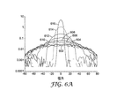
図6Aおよび6Bは、それぞれさまざまなTの値の拡散層からの光の透過についての極座標プロットを示す。図6Aは、実施例7の平坦面について角度依存性の透過を示す。図6Bは、セルの30%平坦と140度の頂角を有する隆起部を備える実施例2について角度依存性の透過を示す。角度は、隆起の方向に垂直な平面で計測される。曲線の番号を、表IIにTの各値とともに示す。 6A and 6B show polar plots for the transmission of light from a diffusion layer of various T values, respectively. FIG. 6A shows angle-dependent transmission for the flat surface of Example 7. FIG. FIG. 6B shows angle-dependent transmission for Example 2 with a 30% flatness of the cell and a ridge with an apex angle of 140 degrees. The angle is measured in a plane perpendicular to the direction of the ridge. The curve numbers are shown in Table II with each value of T.
一般に、実施例2に対応する図6Bにおける曲線は、図6Aのものよりも広く、このことより、少なくともこのタイプの光変向面が光出力をさらに均一にさせるのに役立っているという結論を導く。 In general, the curve in FIG. 6B corresponding to Example 2 is wider than that in FIG. 6A, which concludes that at least this type of light diverting surface helps to make the light output more uniform. Lead.
バックライトユニットに対する計算された照明分散(variance)を、光源および裏面反射板との間の異なった隔離について図7Aおよび図7Bに示す。図7Aは、隔離を15mmと仮定した結果を表し、図7Bは、隔離を20mmと仮定した結果を表す。このような寸法を、反射キャビティの深さとする。それぞれの代表的な光変向面、実施例1〜7、についての分散が、表2に挙げるTの各値について計算された。分散はTに対してプロットして示す。図7Aにおいて、曲線701〜707は、それぞれ実施例1〜7に対応する。図7Bにおいて、曲線711〜717は、それぞれ実施例1〜7に対応する。 The calculated illumination variance for the backlight unit is shown in FIGS. 7A and 7B for different isolations between the light source and the back reflector. FIG. 7A represents the results assuming 15 mm isolation, and FIG. 7B represents the results assuming 20 mm isolation. Such a dimension is the depth of the reflective cavity. The variance for each representative light turning surface, Examples 1-7, was calculated for each value of T listed in Table 2. Variance is plotted against T. In FIG. 7A, curves 701 to 707 correspond to Examples 1 to 7, respectively. In FIG. 7B, curves 711 to 717 correspond to Examples 1 to 7, respectively.
図7Aおよび図7Bの両方において、分散が最小である透過Tmin以下の透過については分散にほとんど違いがない。しかし、Tminを超える透過値に対して違いは顕著である。図7Aにおいて、2つの実施例、実施例1および実施例2は、分散において、平坦なケース(実施例7)についての場合とほとんど同じ最小値を有する。Tminを超える透過レベルに対する分散の増加がより小さいということは、設計者が均一性と光学的スループットをトレードオフする可能性がより高いことを意味する。 In both FIG. 7A and FIG. 7B, there is almost no difference in dispersion for transmission below the transmission T min where the dispersion is minimum. However, the difference in transmission values greater than T min is remarkable. In FIG. 7A, the two examples, Example 1 and Example 2, have almost the same minimum in dispersion as for the flat case (Example 7). The smaller increase in dispersion for transmission levels above T min means that the designer is more likely to trade off uniformity and optical throughput.
図7Bにおいて、違いはより顕著である。平坦なケースにおいて(実施例7)、Tminにおけるよりも高い透過の値に対して分散は早く増加する。すべての構造のケースにおいて(実施例1〜6)、透過の関数としての分散の増加は、平坦なケースの場合よりも低い。分散は、実施例4において特にゆっくり増加し、約86%の単一経路透過に至るまで5%未満の分散を維持する。 In FIG. 7B, the difference is more pronounced. In the flat case (Example 7), the dispersion increases faster for higher transmission values than at Tmin . In all structural cases (Examples 1-6), the increase in dispersion as a function of transmission is lower than in the flat case. Dispersion increases particularly slowly in Example 4, maintaining less than 5% dispersion until about 86% single pass transmission.
光変向面に使用される構造については多くの異なるタイプのプロフィールの使用が可能である。例えば、この構造には、フィルムに対して垂直である垂直面を有する隆起部を含むことができる。このような構造の代表的実施形態を図8に概略的に示す。フィルム800は、隆起部804を含む構造的光変向面802を備えている。図において、隆起部804は、y−軸に平行であると示されている。隆起部804は、所望により、フィルム800に平行な面806、フィルム800に対して角度付された面808、およびフィルム800に垂直な面810の任意の組み合わせを含むことができる。
Many different types of profiles can be used for structures used for light turning surfaces. For example, the structure can include a ridge having a vertical surface that is perpendicular to the film. A representative embodiment of such a structure is schematically illustrated in FIG. The
面は平坦である必要はなく湾曲していても良い。構造は本質的に周期的であってもよいが、そのような要求があるわけではなく、不規則であってもよい。 The surface need not be flat and may be curved. The structure may be periodic in nature, but it is not such a requirement and may be irregular.
モデル3
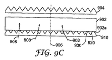
他の代表的実施形態において、光変向面は、拡散層に面するように中間層に配置されることが可能である。このような例を、図9Aに概略的に示す。この例において、プリズム輝度上昇層904は、拡散層902の上にある。他の実施形態において、反射型偏光子層のような異なるタイプの層が、拡散板層902の上に配置されることが可能である。光変向層とも言われる中間層910は、拡散層902の反対側に置かれる。中間層910上の光変向面920は拡散層902に面する。
Model 3
In other exemplary embodiments, the light diverting surface can be disposed in the intermediate layer to face the diffusion layer. Such an example is shown schematically in FIG. 9A. In this example, the prism
実施形態によっては、光変向面920が、拡散層902に例えば接着剤を使用して取り付け可能なものもある。このような配置の代表的実施形態を図9Bに概略的に示し、ここで、面920の一部分が拡散層902の下面903上の接着層922に入り込んでいる。実施形態によっては、接着層922と面920の一部との間にギャップ924が残るものもある。好適な光変向面の1つの代表的実施形態は、プリズム構造面を有する光学フィルムである。このような面を他方の層に接着剤を使用して取り付けることは、米国特許第6,846,089号にさらに詳細に記載されている。
In some embodiments, the
別の代表的実施形態を図9Cに概略的に示し、ここで光変向面920は基本的にプリズム型であるが、拡散層902の下面902aに平行な部分930を含む。プリズム面は、拡散層902の下面902aに押しつけられるか、または下面902aに接着されることが可能である。
Another exemplary embodiment is schematically illustrated in FIG. 9C, where the
図9Bおよび9Cに示したタイプの光変向面を使用するバックライトの特性を検討するため、数値モデリングが使用された。検討した変数の1つは、「%含浸(wet out)」であり、これはプリズム型光変向面について、同じサイズの底辺とプリズム壁同士間の角度を有する三角プリズムに対するプリズムの高さを表わす。これを図9D〜9Eにさらに示す。図9Dにおいて、光変向面920は、面932に対して配置された完全なプリズムを備えている。面932は、接着層または拡散層902の面であり得る。この状況においては0%含浸である。図9Eにおいて、面932は、プリズムが完全な三角柱であるとした場合(点線で示す)のプリズムの高さの50%であろう場所に配置されている。この状況を50%含浸と表わす。100%の含浸は、光変向面が完全に平坦であることと等しい。
Numerical modeling was used to study the characteristics of backlights using light diverting surfaces of the type shown in FIGS. 9B and 9C. One of the variables examined was “% wet out” which, for a prismatic light diverting surface, is the height of the prism relative to a triangular prism having an angle between the base of the same size and the prism walls. Represent. This is further illustrated in FIGS. In FIG. 9D, the
バックライトの照度についてプリズム含浸の関数とした数値結果を図10Aに示す。ここで、10mmの反射キャビティ深さを有するバックライトの照度が曲線1002、15mmのものが曲線1004、および20mmものが曲線1006である。3つすべてのケースにおいて、照度は、拡散層902と輝度上昇層904との間の位置に対して計算されている。計算された照度は、3つの異なるケースについて約60%の含浸でピークとなり、反射キャビティが薄くなると輝度はわずかに増加する。
The numerical results as a function of prism impregnation for backlight illumination are shown in FIG. 10A. Here, the illuminance of a backlight having a reflection cavity depth of 10 mm is a
バックライトの照明の分散についての数値結果を、3つのキャビティ深さ、10mm(曲線1012)、15mm(曲線1014)、および20mm(曲線1016)についての含浸%の関数として図10Bに表す。モデルに対する特定の条件のもとで、最小変動は、15mmおよび20mm厚バックライトに対する含浸範囲20%〜40%、ならびに10mm厚バックライトに対して約65%で生じた。
Numerical results for the backlight illumination distribution are presented in FIG. 10B as a function of percent impregnation for three cavity depths, 10 mm (curve 1012), 15 mm (curve 1014), and 20 mm (curve 1016). Under the specific conditions for the model, the minimum variation occurred in the
モデル4
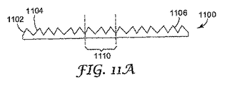
光変向面の形状には、非対称または不規則な要素が含まれ得る。非対称面要素を使用する中間層1100上の光変向面1102の一例を、図11Aに概略的に示す。光変向面1102には、非対称構造要素1104が含まれ、そして対称構造要素1106も含まれることが可能である。光変向面1102を含む中間層1100は、光迂回要素と呼ばれることがある。
Model 4
The shape of the light diverting surface can include asymmetric or irregular elements. An example of a
非対称光迂回要素を伴う光変向要素を有する、バックライトを使用する画像ディスプレイパネルにおける照度が数値モデル化された。このモデルにおいて、光変向要素1100が光変向(面構造要素)の「セル」1110を含み、各セルが2つの可変プリズム1112と、所望により標準プリズム1114を備えるということが仮定された。セル1110の例を図11Bに拡大した形態で示す。可変プリズム1112の2つの特性、プリズム頂角θ、および「カンティング角」α(すなわちプリズム頂角の2等分線が要素1100に対する垂直から回転した角度)、を検討において変化させた。プリズム1112aは、カンティング角αが同一(0度の値)であるが、プリズム1112bの頂角とは異なる頂角θを有する。プリズム1112aおよび1112cは、同一の頂角θを有するが、カンティング角はプリズム1112aおよび1112cについて異なる。αが、0の値を有するとき、可変プリズム要素1112は対称である。
Illuminance in an image display panel using a backlight with a light diverting element with an asymmetric light diverting element was numerically modeled. In this model, it was assumed that the
プリズム頂角の値θは、80°から120°まで変化させ、カンティング角αは、0°から20°まで変化させた。標準プリズム1114は90°の頂角を有すると仮定した。標準プリズム1114が占めるセルの%幅wは、標準プリズム1114が存在しない状態に対応する0%から(図11Bに示す)30%まで変化させた。セルの幅は1mmであり、光源同士間の離隔は30mmであると仮定された。
The prism apex angle value θ was changed from 80 ° to 120 °, and the canting angle α was changed from 0 ° to 20 °. The
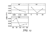
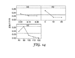
異なるモデル化バックライトから得られた照度の変動の一般的傾向を、10mm深さのバックライト反射キャビティについて図12に示す。図12〜14に表示されたデータは、拡散層902の真上の位置に対する照度計算に基づいている。図12のグラフ(a)は、標準プリズム1114が占める%幅wの関数として照度の変動を示す。0%から30%に増加するwの値に対して照度の変動は概ね小さくなる。グラフ(b)は、可変プリズム1112の頂角θの関数として照度の変動を示す。概ね、頂角が小さくなると、照度の変動が減少する結果となる。グラフ(c)は、カンティング角αの関数として照度の変動を示す。ここで2つの可変プリズム1112が反対方向に+αおよび−α傾けられた。10°のカンティング角に対して分散が減少している。
The general trend of illuminance variation obtained from different modeled backlights is shown in FIG. 12 for a 10 mm deep backlight reflective cavity. The data displayed in FIGS. 12 to 14 is based on the illuminance calculation for the position directly above the
図13および14は、それぞれバックライトキャビティ深さ15mmおよび20mmに対する照度の変動についての同様のデータを表す。15mmおよび20mmキャビティの両方において、wの値が30%まで増加するにつれ分散は下降傾向を示す。15mmキャビティにおいて、約10°のカンティング角αの分散の減少があり、分散は約10°以上のαの値に対して平坦化するように見える。15mmおよび20mmの両方のキャビティでは、10mmキャビティのものとは異なるθの関数としての性質を示し、ここで、80°〜90°の値と比較して、分散の比較的低い値は、100°〜120°の範囲のθの値に対して得られる。 Figures 13 and 14 represent similar data for illuminance variation for backlight cavity depths of 15 mm and 20 mm, respectively. In both 15 mm and 20 mm cavities, the dispersion shows a downward trend as the value of w increases to 30%. In a 15 mm cavity, there is a reduction in dispersion with a canting angle α of about 10 °, and the dispersion appears to flatten for values of α above about 10 °. Both 15 mm and 20 mm cavities exhibit properties as a function of θ that are different from those of 10 mm cavities, where a relatively low value of dispersion is 100 ° compared to values of 80 ° to 90 °. Obtained for values of θ in the range of ~ 120 °.
モデル5
10mmのキャビティ深さを有し、光変向面が含浸と非対称構造の両方を含むバックライトシステムの代表的実施形態の光学的特性をモデル化するため計算が実行された。異なる面のパラメータ(実施例8〜12)を以下の表3にまとめる。実施例8および9は、光変向面の無い簡単な拡散層である。
Calculations were performed to model the optical properties of an exemplary embodiment of a backlight system having a cavity depth of 10 mm and the light diverting surface including both impregnation and asymmetric structures. The parameters of the different surfaces (Examples 8-12) are summarized in Table 3 below. Examples 8 and 9 are simple diffusion layers having no light redirecting surface.
角度αおよびθは、図11Bに規定されたものと同一である。すなわちαは非対称構造についての「カンティング」角であり、θは、「傾斜可能な」光変向面についての頂角である。角度βは、対称な、すなわち傾けられていない光変向構造の頂角である。長さwは、対称光変向構造が占める光変向面上の繰り返しセルの割合である。「含浸」パラメータは、モデル3について上述した%含浸である。拡散層を介する単一経路透過Tがパーセントで与えられる。角度ψは、拡散の半角でありTの関数である。拡散の半角は、最大強度における光と拡散層を通過した後の半分の強度における光との間の角度である。拡散の増加のため拡散層を介する透過が落ちるので、拡散角度は増加する。 The angles α and θ are the same as those defined in FIG. 11B. That is, α is the “canting” angle for the asymmetric structure, and θ is the apex angle for the “tiltable” light turning surface. The angle β is the apex angle of the light turning structure which is symmetric, ie not tilted. The length w is the ratio of repetitive cells on the light diverting plane occupied by the symmetric light diverting structure. The “impregnation” parameter is the% impregnation described above for model 3. The single path transmission T through the diffusion layer is given in percent. The angle ψ is a half-angle of diffusion and is a function of T. The half angle of diffusion is the angle between the light at maximum intensity and the light at half intensity after passing through the diffusion layer. Since the transmission through the diffusion layer falls due to the increase in diffusion, the diffusion angle increases.
図15は、異なる実施例についてバックライトに対する位置の関数として計算された照度を示す。照度は、プリズム型上昇層904の上の位置に対して計算されている。表IVは、それぞれの実施例番号に対するグラフ上の曲線番号を列挙する。表IVは、また、バックライトに対する平均照度L(nit(ニト 輝度の単位;(1Cd/m2))、照度の変動(標準偏差)、および照度における%変動を列挙する。80%拡散板透過を伴う2つの実施例(8および12)は、両方とも高い照度を作り出すが、拡散板単独に対応する実施例8は高い分散を有する。実施例12における分散は、これに対して約1.5%のみである。光変向面を使用する実施例10は、低い分散を有するが、実施例12よりも低い全体の照度を有する。これは、実施例10のTの値が実施例12についてのものよりも低いためである。
FIG. 15 shows the illuminance calculated as a function of position relative to the backlight for the different examples. The illuminance is calculated for a position on the prismatic rising
光変向面は、本明細書には詳細には記載していない多くの異なるタイプの形状を取ることができ、そのような面には、位置、形状、および/または寸法のランダムな光変向要素を有するものが含まれるということが理解されるべきである。さらに、上述した代表的実施形態は、屈折によって照明光を変向する光変向面を目的とするものであるが、他の実施形態においては、照明光を回折することができ、または照明光を屈折と回折の組み合わせで変向することができる。本明細書に記載した計算結果は、異なるタイプと形状の光変向層が、簡単な拡散板のみと比較して、照度を増加させ、照度の変動を減少させる可能性を提供することを示す。 The light diverting surface can take many different types of shapes not described in detail herein, and such surfaces include random light changing in position, shape, and / or dimensions. It should be understood that those having directional elements are included. Furthermore, the exemplary embodiment described above is directed to a light redirecting surface that redirects illumination light by refraction, but in other embodiments, the illumination light can be diffracted or illuminated. Can be changed by a combination of refraction and diffraction. The calculation results described herein show that different types and shapes of light redirecting layers offer the potential to increase illuminance and reduce illuminance variation compared to simple diffusers alone. .
本発明は、上記の特定の実施例に限定されると考えるべきではなく、添付の特許請求の範囲の中で本発明の全局面を包含すると理解されるべきである。本明細書を検討すれば、本発明を適用可能なさまざまな変更例、均等なプロセス、多数の構造は本発明に関連する当業者には容易に明らかになろう。特許請求の範囲はこのような変更例および装置を網羅しようとするものである。 The present invention should not be considered limited to the particular embodiments described above, but is to be understood as encompassing all aspects of the invention within the scope of the appended claims. Upon review of this specification, various modifications, equivalent processes, and numerous structures to which the present invention is applicable will be readily apparent to those skilled in the art to which the present invention relates. The claims are intended to cover such modifications and devices.
添付の図面と共に以下の本発明のさまざまな実施形態の詳細な説明を検討することで本発明がより完全に理解されよう。 A more complete understanding of the invention may be obtained by considering the following detailed description of various embodiments of the invention in conjunction with the accompanying drawings.
本発明はさまざまな変更例および代替形態に順応するが、その具体例を一例として図面に示すとともに詳細に説明してきた。しかし本発明を記載する特定の実施形態に限定しようとするものではないことが理解されるべきである。反対に、本発明は、添付の特許請求の範囲により規定された本発明の精神および範囲内にあるすべての変更例、均等物および代替物を網羅しようとするものである。 While the invention is amenable to various modifications and alternative forms, specific examples thereof have been shown by way of example in the drawings and have been described in detail. It should be understood, however, that the intention is not to limit the invention to the particular embodiments described. On the contrary, the invention is intended to cover all modifications, equivalents, and alternatives falling within the spirit and scope of the invention as defined by the appended claims.
Claims (27)
表示パネルと、
照明光を生成することができる1以上の光源を備え、前記光源が前記表示パネルの背後に配置されている光源装置と、
前記光源装置および前記表示パネルの間に配置された拡散層と、
前記拡散層および前記光源装置の間に配置された中間層であって、前記中間層が前記拡散層に対向する光変向面を備え、前記照明光が前記光変向面を通過するときに、前記光変向面が、前記光源から前記拡散層へ通過する照明光の少なくとも一部の伝搬方向を変向する装置。 A direct illumination type display device,
A display panel;
A light source device comprising one or more light sources capable of generating illumination light, wherein the light sources are arranged behind the display panel;
A diffusion layer disposed between the light source device and the display panel;
An intermediate layer disposed between the diffusion layer and the light source device, wherein the intermediate layer includes a light turning surface facing the diffusion layer, and the illumination light passes through the light turning surface. The device that changes the propagation direction of at least part of the illumination light that passes from the light source to the diffusion layer.
照明光を生成する工程と、
前記照明光を概ね前記表示パネルに向かわせる工程と、
中間層を通過して来る前記照明光を屈折することにより前記照明光の少なくとも一部を変向する工程と、
前記変向された照明光を拡散する工程と、
前記拡散された照明光を前記表示パネルに送る工程と、を備える方法。 A method of operating a display panel,
Generating illumination light; and
Directing the illumination light generally toward the display panel;
Redirecting at least a portion of the illumination light by refracting the illumination light passing through the intermediate layer;
Diffusing the redirected illumination light;
Sending the diffused illumination light to the display panel.
Applications Claiming Priority (2)
| Application Number | Priority Date | Filing Date | Title |
|---|---|---|---|
| US11/129,942 US20070030415A1 (en) | 2005-05-16 | 2005-05-16 | Back-lit displays with high illumination uniformity |
| PCT/US2006/018430 WO2006124588A1 (en) | 2005-05-16 | 2006-05-12 | Back-lit displays with high illumination uniformity |
Publications (2)
| Publication Number | Publication Date |
|---|---|
| JP2008541195A true JP2008541195A (en) | 2008-11-20 |
| JP2008541195A5 JP2008541195A5 (en) | 2009-06-25 |
Family
ID=37431557
Family Applications (1)
| Application Number | Title | Priority Date | Filing Date |
|---|---|---|---|
| JP2008512368A Withdrawn JP2008541195A (en) | 2005-05-16 | 2006-05-12 | Backlit display device with uniform illumination |
Country Status (7)
| Country | Link |
|---|---|
| US (1) | US20070030415A1 (en) |
| EP (1) | EP1882208A4 (en) |
| JP (1) | JP2008541195A (en) |
| KR (1) | KR20080015088A (en) |
| CN (1) | CN101198897A (en) |
| TW (1) | TW200707012A (en) |
| WO (1) | WO2006124588A1 (en) |
Cited By (2)
| Publication number | Priority date | Publication date | Assignee | Title |
|---|---|---|---|---|
| WO2011108295A1 (en) * | 2010-03-02 | 2011-09-09 | シャープ株式会社 | Display panel and display device |
| JP2017525984A (en) * | 2014-04-22 | 2017-09-07 | 深▲ちぇん▼市国華光電科技有限公司 | Display structure provided with high-intensity diffuse reflector and manufacturing method thereof |
Families Citing this family (49)
| Publication number | Priority date | Publication date | Assignee | Title |
|---|---|---|---|---|
| US20060109395A1 (en) * | 2004-11-24 | 2006-05-25 | Junya Yamamoto | Area light source device and liquid crystal display device including the same |
| US8023065B2 (en) * | 2005-06-24 | 2011-09-20 | 3M Innovative Properties Company | Optical element for lateral light spreading in edge-lit displays and system using same |
| US7903194B2 (en) * | 2005-06-24 | 2011-03-08 | 3M Innovative Properties Company | Optical element for lateral light spreading in back-lit displays and system using same |
| KR20070103544A (en) * | 2006-04-19 | 2007-10-24 | 삼성전자주식회사 | Liquid crystal display and prism sheet for the same |
| DE112007002760T5 (en) * | 2006-11-15 | 2009-09-24 | 3M Innovative Properties Co., Saint Paul | Backlight Display with high illumination uniformity |
| US7766528B2 (en) * | 2006-11-15 | 2010-08-03 | 3M Innovative Properties Company | Back-lit displays with high illumination uniformity |
| US7478913B2 (en) * | 2006-11-15 | 2009-01-20 | 3M Innovative Properties | Back-lit displays with high illumination uniformity |
| US7789538B2 (en) | 2006-11-15 | 2010-09-07 | 3M Innovative Properties Company | Back-lit displays with high illumination uniformity |
| US8134656B2 (en) * | 2006-11-29 | 2012-03-13 | Sharp Kabushiki Kaisha | Backlight device, display device, and television receiver |
| US8792070B2 (en) | 2007-03-21 | 2014-07-29 | Honeywell International Inc. | Polarization plate for use in a liquid crystal display |
| JP5393048B2 (en) | 2007-06-29 | 2014-01-22 | 日東電工株式会社 | Liquid crystal display device, laminated polarizing plate, and polarized light source device |
| US20090034268A1 (en) * | 2007-08-01 | 2009-02-05 | 3M Innovative Properties Company | Light management assembly |
| JP2009080214A (en) * | 2007-09-25 | 2009-04-16 | Toshiba Corp | Liquid crystal display device |
| JP2009098263A (en) * | 2007-10-15 | 2009-05-07 | Hitachi Ltd | Liquid crystal display device and illumination device |
| KR100916304B1 (en) * | 2007-11-26 | 2009-09-10 | 엘지전자 주식회사 | Optical Sheet |
| JP5702151B2 (en) * | 2008-02-07 | 2015-04-15 | スリーエム イノベイティブ プロパティズ カンパニー | Hollow backlight with structured film |
| TW200949369A (en) * | 2008-02-15 | 2009-12-01 | 3M Innovative Properties Co | Brightness enhancing film and film based diffuser for improved illumination uniformity of displays |
| JP5405763B2 (en) * | 2008-03-28 | 2014-02-05 | 日東電工株式会社 | Directional diffusion film, polarizing plate, liquid crystal display device, and method of manufacturing directional diffusion film |
| US8220932B2 (en) * | 2009-01-08 | 2012-07-17 | 3M Innovative Properties Company | Dry erasable projection article and system |
| US9291752B2 (en) | 2013-08-19 | 2016-03-22 | 3M Innovative Properties Company | Retroreflecting optical construction |
| JP5727460B2 (en) | 2009-04-15 | 2015-06-03 | スリーエム イノベイティブ プロパティズ カンパニー | Optical film for preventing optical coupling |
| TWI605276B (en) | 2009-04-15 | 2017-11-11 | 3M新設資產公司 | Optical construction and display system incorporating same |
| WO2010120845A2 (en) | 2009-04-15 | 2010-10-21 | 3M Innovative Properties Company | Backlight and display system incorporating same |
| CN102576119B (en) | 2009-10-24 | 2014-03-26 | 3M创新有限公司 | Light source and display system incorporating same |
| CN102667618B (en) | 2009-11-23 | 2015-02-25 | 3M创新有限公司 | Front projection screen with high contrast |
| JP5869494B2 (en) | 2009-12-08 | 2016-02-24 | スリーエム イノベイティブ プロパティズ カンパニー | Optical structure incorporating light guide and low refractive index film |
| KR101954457B1 (en) | 2010-04-15 | 2019-03-05 | 쓰리엠 이노베이티브 프로퍼티즈 캄파니 | Retroreflective articles including optically active areas and optically inactive areas |
| EP2558289B1 (en) | 2010-04-15 | 2018-12-26 | 3M Innovative Properties Company | Retroreflective articles including optically active areas and optically inactive areas |
| WO2011129833A1 (en) | 2010-04-15 | 2011-10-20 | 3M Innovative Properties Company | Retroreflective articles including optically active areas and optically inactive areas |
| JP2012083744A (en) * | 2010-09-17 | 2012-04-26 | Nitto Denko Corp | Light-diffusing element and polarizing plate with light-diffusing element |
| JP6275934B2 (en) | 2010-09-17 | 2018-02-07 | 日東電工株式会社 | Light diffusing element, polarizing plate with light diffusing element, polarizing element, and liquid crystal display using the same |
| JP6275936B2 (en) | 2010-09-17 | 2018-02-07 | 日東電工株式会社 | Light diffusing film, polarizing plate with light diffusing film, liquid crystal display device and lighting apparatus |
| JP6275935B2 (en) | 2010-09-17 | 2018-02-07 | 日東電工株式会社 | Light diffusing element, polarizing plate with light diffusing element, and liquid crystal display using the same |
| TW201227077A (en) * | 2010-12-16 | 2012-07-01 | Chunghwa Picture Tubes Ltd | Liquid crystal display device and backlight module thereof |
| JP2014517931A (en) | 2011-04-28 | 2014-07-24 | ドルビー ラボラトリーズ ライセンシング コーポレイション | Dual panel display with cross BEF collimator and polarization preserving diffuser |
| JP5953835B2 (en) * | 2011-09-07 | 2016-07-20 | セイコーエプソン株式会社 | projector |
| CN104216168A (en) * | 2013-05-29 | 2014-12-17 | 鸿富锦精密工业(深圳)有限公司 | Liquid crystal display device and backlight module thereof |
| CN103955011A (en) * | 2014-04-21 | 2014-07-30 | 深圳市国华光电科技有限公司 | Display structure with high-brightness diffuse reflector and manufacturing method thereof |
| US10642087B2 (en) | 2014-05-23 | 2020-05-05 | Eyesafe, Llc | Light emission reducing compounds for electronic devices |
| KR101728678B1 (en) * | 2015-05-18 | 2017-05-02 | 주식회사 엘엠에스 | Reflective Polarizing Module Having Particle and Back Light Unit Having the Same |
| CN105445829B (en) * | 2016-01-08 | 2018-05-25 | 京东方光科技有限公司 | Prism film, light guide plate, backlight module and display device |
| CN107748468A (en) * | 2017-11-30 | 2018-03-02 | 青岛海信电器股份有限公司 | Liquid crystal display device |
| CN108303822A (en) * | 2018-01-23 | 2018-07-20 | 青岛海信电器股份有限公司 | A kind of backlight module, display device and LCD TV |
| CN112771441B (en) * | 2018-09-28 | 2023-10-10 | 株式会社巴川制纸所 | Light guide laminate using anisotropic optical film and planar lighting device for display device using the same |
| US11347099B2 (en) * | 2018-11-28 | 2022-05-31 | Eyesafe Inc. | Light management filter and related software |
| US11810532B2 (en) | 2018-11-28 | 2023-11-07 | Eyesafe Inc. | Systems for monitoring and regulating harmful blue light exposure from digital devices |
| US11592701B2 (en) | 2018-11-28 | 2023-02-28 | Eyesafe Inc. | Backlight unit with emission modification |
| CN114258510A (en) * | 2019-08-19 | 2022-03-29 | 3M创新有限公司 | Display system |
| CN114280842A (en) * | 2021-12-21 | 2022-04-05 | Tcl华星光电技术有限公司 | Backlight module, display device and electronic equipment |
Family Cites Families (70)
| Publication number | Priority date | Publication date | Assignee | Title |
|---|---|---|---|---|
| US3566102A (en) * | 1967-09-13 | 1971-02-23 | Artcrest Products Co Inc | Light panel |
| US3721818A (en) * | 1970-05-18 | 1973-03-20 | Ksh Inc | Ceiling mounted luminaire and light-transmitting enclosure therefor |
| US4173399A (en) * | 1976-09-13 | 1979-11-06 | Izon Corporation | Compact optical viewer for microfiche or cassette |
| US4497860A (en) * | 1978-12-18 | 1985-02-05 | Minnesota Mining And Manufacturing Company | Imageable prismatic array |
| US4268118A (en) * | 1979-09-05 | 1981-05-19 | Minnesota Mining And Manufacturing Company | Sheeting useful as a projection screen |
| US4708435A (en) * | 1986-10-30 | 1987-11-24 | Mitsubishi Rayon Co., Ltd. | Rear projection screen |
| CA1278203C (en) * | 1987-04-24 | 1990-12-27 | Lorne A. Whitehead | Non-reflective image display device |
| US4791540A (en) * | 1987-05-26 | 1988-12-13 | Minnesota Mining And Manufacturing Company | Light fixture providing normalized output |
| US5161041A (en) * | 1990-04-26 | 1992-11-03 | Ois Optical Imaging Systems, Inc. | Lighting assembly for a backlit electronic display including an integral image splitting and collimating means |
| USRE37377E1 (en) * | 1992-10-09 | 2001-09-18 | Asahi Glass Company, Ltd. | LCD device including an illumination device having a polarized light separating sheet between a light guide and the display |
| TW289095B (en) * | 1993-01-11 | 1996-10-21 | ||
| US5882774A (en) * | 1993-12-21 | 1999-03-16 | Minnesota Mining And Manufacturing Company | Optical film |
| US5659410A (en) * | 1993-12-28 | 1997-08-19 | Enplas Corporation | Surface light source device and liquid crystal display |
| US5751388A (en) * | 1995-04-07 | 1998-05-12 | Honeywell Inc. | High efficiency polarized display |
| JP3653308B2 (en) * | 1995-08-01 | 2005-05-25 | 日東樹脂工業株式会社 | Surface light source device and liquid crystal display |
| EP0819970B1 (en) * | 1996-02-07 | 2006-08-30 | Nitto Jushi Kogyo Kabushiki Kaisha | Surface light source device, liquid crystal display and asymmetric prism sheet |
| US5867316A (en) * | 1996-02-29 | 1999-02-02 | Minnesota Mining And Manufacturing Company | Multilayer film having a continuous and disperse phase |
| US5825543A (en) * | 1996-02-29 | 1998-10-20 | Minnesota Mining And Manufacturing Company | Diffusely reflecting polarizing element including a first birefringent phase and a second phase |
| JP3655970B2 (en) * | 1996-07-29 | 2005-06-02 | 大日本印刷株式会社 | Transmission screen |
| US6497946B1 (en) * | 1997-10-24 | 2002-12-24 | 3M Innovative Properties Company | Diffuse reflective articles |
| US6327598B1 (en) * | 1997-11-24 | 2001-12-04 | International Business Machines Corporation | Removing a filled-out form from a non-interactive web browser cache to an interactive web browser cache |
| TW518440B (en) * | 1998-03-25 | 2003-01-21 | Enplas Corp | Surface light source device of side light type and liquid crystal display |
| KR100271672B1 (en) * | 1998-05-20 | 2000-11-15 | 구본준 | Sheet type optical device and backlight unit using the same |
| US6617784B1 (en) * | 1998-06-08 | 2003-09-09 | 3M Innovative Properties Company | Electroluminescent device and method for producing the same |
| US6055108A (en) * | 1999-02-11 | 2000-04-25 | Minnesota Mining And Manufacturing Company | Imaging articles and methods using dual-axis retroreflective elements |
| US6827456B2 (en) * | 1999-02-23 | 2004-12-07 | Solid State Opto Limited | Transreflectors, transreflector systems and displays and methods of making transreflectors |
| US6122103A (en) * | 1999-06-22 | 2000-09-19 | Moxtech | Broadband wire grid polarizer for the visible spectrum |
| US6356389B1 (en) * | 1999-11-12 | 2002-03-12 | Reflexite Corporation | Subwavelength optical microstructure light collimating films |
| US6636981B1 (en) * | 2000-01-06 | 2003-10-21 | International Business Machines Corporation | Method and system for end-to-end problem determination and fault isolation for storage area networks |
| JP2001202814A (en) * | 2000-01-21 | 2001-07-27 | Bridgestone Corp | Down light type of flat luminous body |
| KR20020041431A (en) * | 2000-07-11 | 2002-06-01 | 미우라 아키라 | Surface light source device |
| DE60036733T2 (en) * | 2000-07-24 | 2008-07-17 | Mitsubishi Rayon Co., Ltd. | SURFACE LIGHTING DEVICE |
| JP2002049324A (en) * | 2000-07-31 | 2002-02-15 | Nippon Seiki Co Ltd | Back light device |
| US6595652B2 (en) * | 2000-12-12 | 2003-07-22 | International Manufacturing And Engineering Services Co., Ltd. | Surface lighting device |
| TW574509B (en) * | 2001-02-14 | 2004-02-01 | Yuka Denshi Co Ltd | Light guide body, light reflective sheet and surface light source device and liquid crystal device using the light reflective sheet, and the manufacturing method of light reflective sheet |
| KR100765304B1 (en) * | 2001-02-21 | 2007-10-09 | 삼성전자주식회사 | Backlight assembly and liquid crystal display device having the same |
| US6917399B2 (en) * | 2001-02-22 | 2005-07-12 | 3M Innovative Properties Company | Optical bodies containing cholesteric liquid crystal material and methods of manufacture |
| JP4293300B2 (en) * | 2001-05-24 | 2009-07-08 | シャープ株式会社 | Illumination device and display device including the same |
| TW589470B (en) * | 2001-10-04 | 2004-06-01 | Mitsubishi Rayon Co | Planar light source device and light guide therefor |
| TWI258023B (en) * | 2001-11-07 | 2006-07-11 | Ibm | A prism sheet, a back-light unit using said prism sheet, and a transmission type liquid crystal display device |
| JP4133420B2 (en) * | 2002-03-26 | 2008-08-13 | シャープ株式会社 | Backlight and liquid crystal display device |
| FR2838179B1 (en) * | 2002-04-05 | 2004-12-24 | Phlox | BACKLIGHT APPARATUS |
| US6846098B2 (en) * | 2002-05-16 | 2005-01-25 | Eastman Kodak Company | Light diffuser with variable diffusion |
| KR20030097143A (en) * | 2002-06-19 | 2003-12-31 | 엘지.필립스 엘시디 주식회사 | The backlight unit of liquid crystal display |
| KR100897745B1 (en) * | 2002-06-26 | 2009-05-15 | 삼성전자주식회사 | Back light assembly and direct type liquid crystal display |
| DK1517174T3 (en) * | 2002-06-27 | 2012-04-16 | Dainippon Printing Co Ltd | Projection screen and projection display device |
| KR20040031858A (en) * | 2002-10-04 | 2004-04-14 | 삼성전자주식회사 | Liquid crystal display |
| KR20040074789A (en) * | 2003-02-19 | 2004-08-26 | 삼성전자주식회사 | Backlight assembly and liquid crystal display having the same |
| KR100725011B1 (en) * | 2003-11-12 | 2007-06-04 | 엘지전자 주식회사 | Prism sheet and back light assembly |
| US6846089B2 (en) * | 2003-05-16 | 2005-01-25 | 3M Innovative Properties Company | Method for stacking surface structured optical films |
| US6997595B2 (en) * | 2003-08-18 | 2006-02-14 | Eastman Kodak Company | Brightness enhancement article having trapezoidal prism surface |
| US7224529B2 (en) * | 2003-09-09 | 2007-05-29 | 3M Innovative Properties Company | Microreplicated article |
| US7213933B2 (en) * | 2004-01-02 | 2007-05-08 | Entire Technology Co., Ltd. | Direct type backlight module of diffuser plate and its manufacturing method thereof |
| US7142768B2 (en) * | 2004-03-04 | 2006-11-28 | K-Bridge Electronics Co., Ltd. | LCD optical waveguide device |
| TWI364600B (en) * | 2004-04-12 | 2012-05-21 | Kuraray Co | An illumination device an image display device using the illumination device and a light diffusing board used by the devices |
| US7408708B2 (en) * | 2004-04-16 | 2008-08-05 | Dai Nippon Printing Co., Ltd. | Diffusing sheet, surface light source unit, and transmission type display |
| TW200600919A (en) * | 2004-06-22 | 2006-01-01 | Samsung Electronics Co Ltd | Optical film, backlight assembly and liquid crystal display device having the same |
| US7446827B2 (en) * | 2004-10-15 | 2008-11-04 | 3M Innovative Properties Company | Direct-lit liquid crystal displays with laminated diffuser plates |
| US7436469B2 (en) * | 2004-10-15 | 2008-10-14 | 3M Innovative Properties Company | Composite diffuser plates and direct-lit liquid crystal displays using same |
| TWI248543B (en) * | 2004-11-10 | 2006-02-01 | Coretronic Corp | Bottom-lit backlight module |
| JP4433467B2 (en) * | 2004-12-01 | 2010-03-17 | 株式会社エンプラス | Surface light source device |
| US7339635B2 (en) * | 2005-01-14 | 2008-03-04 | 3M Innovative Properties Company | Pre-stacked optical films with adhesive layer |
| US7220036B2 (en) * | 2005-05-20 | 2007-05-22 | 3M Innovative Properties Company | Thin direct-lit backlight for LCD display |
| US8023065B2 (en) * | 2005-06-24 | 2011-09-20 | 3M Innovative Properties Company | Optical element for lateral light spreading in edge-lit displays and system using same |
| US20070002588A1 (en) * | 2005-07-01 | 2007-01-04 | K-Bridge Electronics Co., Ltd. | Backlight module light equilibrator |
| KR101298786B1 (en) * | 2005-08-27 | 2013-08-22 | 쓰리엠 이노베이티브 프로퍼티즈 컴파니 | Illumination assembly and system |
| US7663712B2 (en) * | 2005-10-10 | 2010-02-16 | Skc Haas Display Films Co., Ltd. | Backlight unit with linearly reduced divergence having the width of an output aperture vary over the length of a light divergence reduction structure |
| JP4307477B2 (en) * | 2006-07-04 | 2009-08-05 | 三星モバイルディスプレイ株式會社 | Light guide plate and backlight unit |
| CN101295041B (en) * | 2007-04-27 | 2011-12-21 | 鸿富锦精密工业(深圳)有限公司 | Back light module and optical plate |
| KR100985358B1 (en) * | 2007-12-10 | 2010-10-04 | 히다치 가세고교 가부시끼가이샤 | Backlight unit |
-
2005
- 2005-05-16 US US11/129,942 patent/US20070030415A1/en not_active Abandoned
-
2006
- 2006-05-12 KR KR1020077027436A patent/KR20080015088A/en not_active Application Discontinuation
- 2006-05-12 WO PCT/US2006/018430 patent/WO2006124588A1/en active Application Filing
- 2006-05-12 JP JP2008512368A patent/JP2008541195A/en not_active Withdrawn
- 2006-05-12 CN CNA2006800217303A patent/CN101198897A/en active Pending
- 2006-05-12 EP EP06759668A patent/EP1882208A4/en not_active Withdrawn
- 2006-05-15 TW TW095117112A patent/TW200707012A/en unknown
Cited By (2)
| Publication number | Priority date | Publication date | Assignee | Title |
|---|---|---|---|---|
| WO2011108295A1 (en) * | 2010-03-02 | 2011-09-09 | シャープ株式会社 | Display panel and display device |
| JP2017525984A (en) * | 2014-04-22 | 2017-09-07 | 深▲ちぇん▼市国華光電科技有限公司 | Display structure provided with high-intensity diffuse reflector and manufacturing method thereof |
Also Published As
| Publication number | Publication date |
|---|---|
| EP1882208A4 (en) | 2009-12-23 |
| CN101198897A (en) | 2008-06-11 |
| TW200707012A (en) | 2007-02-16 |
| KR20080015088A (en) | 2008-02-18 |
| WO2006124588A1 (en) | 2006-11-23 |
| US20070030415A1 (en) | 2007-02-08 |
| EP1882208A1 (en) | 2008-01-30 |
Similar Documents
| Publication | Publication Date | Title |
|---|---|---|
| JP2008541195A (en) | Backlit display device with uniform illumination | |
| US7766528B2 (en) | Back-lit displays with high illumination uniformity | |
| US7789538B2 (en) | Back-lit displays with high illumination uniformity | |
| US9001286B2 (en) | Brightness enhancing film and film based diffuser for improved illumination uniformity of displays | |
| US8690373B2 (en) | Back-lit displays with high illumination uniformity | |
| US7220036B2 (en) | Thin direct-lit backlight for LCD display | |
| TWI417614B (en) | Back-lit displays with high illumination uniformity | |
| KR101277872B1 (en) | Multi-function enhancement film | |
| US7766531B2 (en) | Edge-lit optical display with fluted optical plate | |
| JP5819723B2 (en) | Hollow backlight with tilted light source | |
| US20080111947A1 (en) | Back-lit displays with high illumination uniformity | |
| KR20070028385A (en) | Diffusive reflector film for liquid crystal display backlight | |
| KR20080091342A (en) | Light management film package for display systems and systems using same | |
| US8052319B2 (en) | Diffusion plate and display apparatus having the same |
Legal Events
| Date | Code | Title | Description |
|---|---|---|---|
| A521 | Written amendment |
Free format text: JAPANESE INTERMEDIATE CODE: A523 Effective date: 20090511 |
|
| A621 | Written request for application examination |
Free format text: JAPANESE INTERMEDIATE CODE: A621 Effective date: 20090511 |
|
| A761 | Written withdrawal of application |
Free format text: JAPANESE INTERMEDIATE CODE: A761 Effective date: 20100729 |