CN101390002A - Optical display with fluted optical plate - Google Patents
Optical display with fluted optical plate Download PDFInfo
- Publication number
- CN101390002A CN101390002A CNA2007800061516A CN200780006151A CN101390002A CN 101390002 A CN101390002 A CN 101390002A CN A2007800061516 A CNA2007800061516 A CN A2007800061516A CN 200780006151 A CN200780006151 A CN 200780006151A CN 101390002 A CN101390002 A CN 101390002A
- Authority
- CN
- China
- Prior art keywords
- layer
- web member
- optical control
- grooved drum
- control layer
- Prior art date
- Legal status (The legal status is an assumption and is not a legal conclusion. Google has not performed a legal analysis and makes no representation as to the accuracy of the status listed.)
- Pending
Links
Images


Classifications
-
- G—PHYSICS
- G02—OPTICS
- G02F—OPTICAL DEVICES OR ARRANGEMENTS FOR THE CONTROL OF LIGHT BY MODIFICATION OF THE OPTICAL PROPERTIES OF THE MEDIA OF THE ELEMENTS INVOLVED THEREIN; NON-LINEAR OPTICS; FREQUENCY-CHANGING OF LIGHT; OPTICAL LOGIC ELEMENTS; OPTICAL ANALOGUE/DIGITAL CONVERTERS
- G02F1/00—Devices or arrangements for the control of the intensity, colour, phase, polarisation or direction of light arriving from an independent light source, e.g. switching, gating or modulating; Non-linear optics
- G02F1/01—Devices or arrangements for the control of the intensity, colour, phase, polarisation or direction of light arriving from an independent light source, e.g. switching, gating or modulating; Non-linear optics for the control of the intensity, phase, polarisation or colour
- G02F1/13—Devices or arrangements for the control of the intensity, colour, phase, polarisation or direction of light arriving from an independent light source, e.g. switching, gating or modulating; Non-linear optics for the control of the intensity, phase, polarisation or colour based on liquid crystals, e.g. single liquid crystal display cells
- G02F1/133—Constructional arrangements; Operation of liquid crystal cells; Circuit arrangements
- G02F1/1333—Constructional arrangements; Manufacturing methods
- G02F1/1335—Structural association of cells with optical devices, e.g. polarisers or reflectors
- G02F1/1336—Illuminating devices
- G02F1/133602—Direct backlight
- G02F1/133606—Direct backlight including a specially adapted diffusing, scattering or light controlling members
-
- G—PHYSICS
- G02—OPTICS
- G02B—OPTICAL ELEMENTS, SYSTEMS OR APPARATUS
- G02B5/00—Optical elements other than lenses
- G02B5/30—Polarising elements
-
- G—PHYSICS
- G02—OPTICS
- G02F—OPTICAL DEVICES OR ARRANGEMENTS FOR THE CONTROL OF LIGHT BY MODIFICATION OF THE OPTICAL PROPERTIES OF THE MEDIA OF THE ELEMENTS INVOLVED THEREIN; NON-LINEAR OPTICS; FREQUENCY-CHANGING OF LIGHT; OPTICAL LOGIC ELEMENTS; OPTICAL ANALOGUE/DIGITAL CONVERTERS
- G02F1/00—Devices or arrangements for the control of the intensity, colour, phase, polarisation or direction of light arriving from an independent light source, e.g. switching, gating or modulating; Non-linear optics
- G02F1/01—Devices or arrangements for the control of the intensity, colour, phase, polarisation or direction of light arriving from an independent light source, e.g. switching, gating or modulating; Non-linear optics for the control of the intensity, phase, polarisation or colour
- G02F1/13—Devices or arrangements for the control of the intensity, colour, phase, polarisation or direction of light arriving from an independent light source, e.g. switching, gating or modulating; Non-linear optics for the control of the intensity, phase, polarisation or colour based on liquid crystals, e.g. single liquid crystal display cells
- G02F1/133—Constructional arrangements; Operation of liquid crystal cells; Circuit arrangements
- G02F1/1333—Constructional arrangements; Manufacturing methods
- G02F1/1335—Structural association of cells with optical devices, e.g. polarisers or reflectors
Abstract
A display system has a light source, a display panel and an arrangement of light management layers disposed between the light source and the display panel. The light source illuminates the display panel through the arrangement of light management layers. The arrangement of light management layers includes a fluted plate that has a front layer facing the display panel, a back layer facing the light source, and a plurality of connecting members connecting the front and back layers. In some embodiments the fluted plate includes a first light management layer, a cross member substantially parallel to, and spaced apart from, the first light management layer, and an arrangement of first connecting members connecting the cross member and the first light management layer.
Description
Technical field
The present invention relates to optical display, more particularly, relate to the display system of back lighting, for example, can be used for the display system in LCD monitor and the liquid crystal TV set.
Background technology
LCD (LCD) is the optical display that uses in the device such as laptop computer, hand-held calculator, electronic watch and televisor.Some LCD comprise the light source that is positioned at display side, and it is provided with light guide with the back side of light from light source guiding panel of LCD.Other LCD, for example some LCD monitor and liquid crystal TV set (LCD-TV) adopt a plurality of light source direct illuminations that are arranged on the panel of LCD rear.Bigger display adopts this structure more prevalently, this is because in order to reach certain display brightness level, light power requirements is with square increase of display sizes, and the space that can be used for being provided with along display side light source only increases linearly with the size of display.In addition, some liquid crystal display applications (for example liquid crystal TV set) require displaying contents enough bright, watch in farther distance so that use mutually specific energy, and the visual angle of liquid crystal TV set requires generally to be different from the visual angle requirement of LCD monitor and hand-held device with other.
Some LCD monitor and most of liquid crystal TV set generally by a plurality of cold-cathode fluorescence lamps (CCFL) from back lighting.These light sources are linear and extend on the whole width of display, consequently utilize by the back side of illuminating display than the separated a series of bright fringess of dark areas.Such Illumination Distribution is worthless, therefore uses diffuser plate to make the Illumination Distribution on the liquid crystal indicator back side level and smooth.
At present, what the diffuser plate of liquid crystal TV set adopted is the polymer substrate that is combined with multiple disperse phase, this polymer substrate is made of the random copolymers of polymethylmethacrylate (PMMA), polycarbonate, cycloolefin and polymethylmethacrylate or polystyrene, and this disperse phase comprises glass, polystyrene beads and CaCO
3Particle.These diffuser plates can deform or warpage after under being exposed to the high temperature of lamp usually.In addition, some diffuser plates have on whole diffuser plate width the diffusion property with spatial variations, so that make the Illumination Distribution at the panel of LCD back side more even.Sometimes this uneven diffuser plate is called printed pattern diffusers.This diffuser plate manufactures expensive, and can increase manufacturing cost, and this is because must be with diffusion patterned aligning lighting source when assembling.In addition, these diffuser plates also need special-purpose to extrude the compounding operation so that granule proliferation is evenly distributed in the whole polymer substrate, and this has further increased cost.
In addition, in order to prevent the physical deformation of warpage or other type, diffuser plate must have the minimum thickness for its height and width.Along with the increase of display sizes, this means that diffuser plate also becomes more and more thicker, thereby the weight of display can increase.
Summary of the invention
One embodiment of the present of invention relate to such display system: this display system have light source, display panel and be arranged on this light source and this display panel between optical control layer structure.This light source sees through the optical control layer structure display panel is thrown light on.Optical control layer structure comprises such grooved drum plate: this grooved drum plate has towards the anterior layer of described display panel, towards the back layer of described light source and connect described anterior layer and a plurality of web members of back layer.
An alternative embodiment of the invention relates to the light control unit that comprises channeled layer.This channeled layer have first optical control layer, with the first optical control layer almost parallel and spatially with the isolated cross member of described first optical control layer, and first web member structure that described cross member is connected to first optical control layer.
According to following detailed, these and other aspect of present patent application will be conspicuous.Yet under any circumstance, it is restriction to claimed theme that above content all should not be construed as, and this theme only is subjected to the qualification of appended claims, can revise it in the patented claim process.
Description of drawings
With reference to following to the detailed description that various embodiment of the present invention did, can more fully understand the present invention in conjunction with the accompanying drawings, similarly Reference numeral is represented similar elements in the accompanying drawings, wherein:
Fig. 1 schematically shows the display device of using grooved drum plate;
Fig. 2 A schematically shows grooved drum plate;
Fig. 2 B and 2C schematically show the attached grooved drum plate that optical thin film is arranged;
Fig. 3 schematically shows the grooved drum plate with single pass transmission variable on the space;
Fig. 4 schematically shows the grooved drum plate with refractive index variable on the space;
Fig. 5 A and 5B schematically show the grooved drum plate that its upper and lower have the thickness that changes on the space respectively;
Fig. 6 A and 6B schematically show the grooved drum plate that its upper and lower have the thickness that changes on the space respectively;
Fig. 7 A, 7B schematically show the grooved drum plate with the different groove of shape of cross section with 7C;
Fig. 8 A schematically shows the vertical view of grooved drum plate, and it shows the groove that is arranged in parallel;
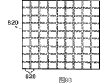
Fig. 8 B schematically shows the vertical view of grooved drum plate, and it shows vertically arranged many group parallel grooves;
Fig. 9 and 10 schematically shows the grooved drum plate with surface structure useful on the optics;
Figure 11 A, 11B, 12A and 12B schematically show the multiple optical thin film structure that comprises grooved drum plate;
Figure 13 A and 13B schematically show the structure that uses with the grooved drum plate of the attached ridge of optical thin film;
Figure 14 A and 14B schematically show the structure that uses with the grooved drum plate of the attached two-sided ridge of optical thin film;
Figure 15 and 16 schematically shows and is structured in two-sided ridge different film configuration on every side;
Figure 17 schematically shows the structure of the grooved drum plate that uses the ground floor with interconnecting component and the second layer; And
Figure 18 schematically shows the display system of the heat transmission medium stream with the groove that flows through grooved drum plate.
The present invention can have multiple modification and alternative form, and its concrete condition illustrates by way of example in the accompanying drawings and will be described in detail hereinafter.Yet should be appreciated that the present invention is not subjected to the restriction of described specific embodiment.On the contrary, whole modification, equivalents and the alternative form that belongs in the spirit and scope of the present invention that are limited by the accompanying claims contained in the present invention.
Embodiment
The present invention is applicable to LCD (LCD or LC display), and is applicable to and back side direct illumination formula LCD and edge-lit LCD for example, is used for the LCD of LCD monitor and liquid crystal TV set (LCD-TV).
The diffuser plate that uses in liquid crystal TV set at present is all based on the polymer substrate that forms rigid sheet (for example, polymethylmethacrylate (PMMA), polycarbonate (PC) or cycloolefin).This thin slice comprises granule proliferation, for example, and organic granular, inorganic particle or space (bubble).These plates be exposed to be used under the high temperature of light source of illuminated displays after, usually can deform or warpage.Make these plates and its cost that is assembled in the final display device is also more expensive.
Present patent application discloses direct illumination formula liquid crystal indicator, and this liquid crystal indicator has the optical control layer structure that is arranged between panel of LCD self and the light source.This optical control layer structure can comprise diffusion layer, and the transmissivity of this diffusion layer is designed to be used to provide the direct illumination formula LCD that has relative brightness uniformly on whole display with level of haze.
Fig. 1 shows the schematic, exploded of exemplary direct illumination formula liquid crystal indicator 100.This type of display device 100 can be used for (for example) LCD monitor or liquid crystal TV set.The basis of display device 100 is uses of liquid crystal panel 102, and this liquid crystal panel generally includes the liquid crystal layer 104 that is arranged between the display panel substrate 106.Display panel substrate 106 is formed by glass usually, and can comprise electrode structure and the both alignment layers that is arranged in liquid crystal aligning on its inside surface, that be used to control liquid crystal layer 104.Electrode structure is arranged to be used to limit the pixel of liquid crystal panel usually, and described pixel is can be independent of the zone that adjacent area is controlled liquid crystal aligning in the liquid crystal layer.One or more display panel substrates 106 also can comprise the color filter that is used for applying color on the image that shows.
Last absorptive polarizers 108 is arranged on the liquid crystal layer 104, and following absorptive polarizers 110 is arranged under the liquid crystal layer 104.In the illustrated embodiment, upper and lower absorptive polarizers all is positioned at outside the liquid crystal panel 102.Absorptive polarizers 108,110 and liquid crystal panel 102 jointly control the transmission process that arrives the observer from the light of backlight 112 by display device 100.In some LCD, can be arranged to make its axis of homology vertical mutually absorptive polarizers 108,110.When the pixel un-activation of liquid crystal layer 104, this pixel can not change the polarization state of light that passes therethrough.Correspondingly, when absorptive polarizers 108,110 homeotropic alignments, the light that passes down absorptive polarizers 110 is absorbed by last absorptive polarizers 108.On the other hand, when pixel is activated, rotate from the polarization state of light of wherein passing through, thus make have at least in the light of transmission by following absorptive polarizers 110 part also transmission by last absorptive polarizers 108.For example, the different pixels by 114 pairs of liquid crystal layers 104 of controller optionally activates, and makes light penetrate from display in some desired position, thereby forms the image that the observer sees.This controller can comprise (for example) computing machine or reception and show the TV set controller of television image.Can be provided with one or more optional layers 109 on last absorptive polarizers 108, (for example) is so that provide machinery and/or environmental protection to display surface.In one exemplary embodiment, layer 109 can comprise the hard coat that is positioned at absorptive polarizers 108 tops.
The working method that should be appreciated that the LCD of some types can be different with aforesaid way.For example, absorptive polarizers can be arranged in parallel, and liquid crystal panel can make polarization state of light rotate under unactivated state.In any case the basic structure of this display is still similar to above-mentioned basic structure.
Backlight 112 comprises a plurality of light sources 116 of the light that produces illumination liquid crystal panel 102.The linear cold cathode fluorescent tube that extends in display device 100 is usually as the light source 116 in the display device 100.Yet, also can use the light source of other type, for example, incandescent lamp or arc lamp, light emitting diode (LED), laser instrument, plane fluorescent plate or external electrode fluorescent lamp.This list of light sources is not that intention limits or exhaustive list, and only is exemplary.
Backlight 112 can also comprise reverberator 118, and this reverberator 118 is used to reflect from light source 116 along the light that is directed downwards propagation that deviates from liquid crystal panel 102.As described below, reverberator 118 can also be used for recycling the light of display device 100.Reverberator 118 can be a specular reflector, perhaps can be diffuse reflector.An example of specular reflector that can be used as reverberator 118 is for can derive from 3M Company (St.Paul, Vikuiti Minnesota)
TMEnhanced specular reflectivity (ESR) film (Vikuiti
TMEnhanced Specular Reflection (ESR) film).The example of suitable diffuse reflector comprises the polymkeric substance that is filled with such as diffuse reflective particles such as titania, barium sulphate, lime carbonate, for example, and polyethylene terephthalate (PET), polycarbonate (PC), polypropylene, polystyrene etc.Other example of diffuse reflector (comprise poromerics and contain fibril material) is at United States Patent (USP) 6,780, describes to some extent among 355 people such as () Kretman.
Optical control layer structure 120 is arranged between backlight 112 and the liquid crystal panel 102.This optical control layer influence is propagated the light of coming out from backlight 112, to improve the operating performance of display device 100.For example, optical control layer structure 120 can comprise diffusion layer 122.Diffusion layer 122 is used to spread the light that receives from light source, and this can improve the illumination uniformity of light that incides on the liquid crystal panel 102.Thereby make the observer feel that the brightness of image is more even.Diffusion layer 122 can comprise the body granule proliferation that is distributed in the whole layer, maybe can comprise one or more surface diffusion structures, or comprise its combination.
Optical control layer structure 120 can also comprise gain diffuser, and this gain diffuser is the layer that light is mainly spread to direction of observation.In certain embodiments, gain diffuser comprises from the transparent grain of film surface projection, thereby provides focal power for the light that passes these particles.This can reduce dispersing of light, thereby makes on-axis luminance increase, and this is called as gain sometimes.The gain diffuser of some types has more detailed description in U.S. Patent No. 6,572 among 961 (people such as Koyama).
Optical control layer structure 120 can also comprise reflective polarizer 124.Light source 116 produces nonpolarized lights usually, but the absorptive polarizers 110 single a kind of polarization state of transmission only down, so has half can not be transmitted to liquid crystal layer 104 approximately in the light that produces of light source 116.Yet, can use reflective polarizer 124 to be reflected in the light that absorptive polarizers absorbs under the meeting quilt under the situation that this reflecting polarizer device is not set, thereby can recycle these light by the reflection between reflective polarizer 124 and reverberator 118.At least a portion in the light that the polarizer 124 that is reflected reflects can be by depolarization, subsequently can transmission returning reflective polarizer 124 by the polarization state that reflective polarizer 124 and following absorptive polarizers 110 arrive liquid crystal layers 104.Like this, reflective polarizer 124 can be used for increasing the ratio that light that light source 116 sends arrives the light of liquid crystal layer 104, thereby the image that makes display device 100 be produced is more bright.
Can use the reflective polarizer of any adequate types, for example, multilayer optical film (MOF) reflective polarizer; Such as diffuse reflective polarizing films (DRPF) such as external phase/disperse phase polarizer, wire grid type reflective polarizer or cholesteric reflective polarizer.
MOF reflective polarizer and external phase/disperse phase reflective polarizer all relies on the refractive index difference between at least two kinds of materials (being generally polymeric material) optionally to reflect a kind of light of polarization state, and the light of transmission orthogonal polarization state.Some examples of MOF reflective polarizer have been described in the U.S. Patent No. of owning together 5,882,774 (people such as Jonza).The example of the MOF reflective polarizer of commercially available acquisition comprises Vikuiti
TMDBEF-D200 and DBEF-D440 reflection multilayer polarizer, these polarizers comprise diffusing surface and can derive from 3M Company (St.Paul, Minnesota).
The example of suitable DRPF is included in the U.S. Patent No. of owning together 5,825, external phase/disperse phase the reflective polarizer described among 543 people such as () Ouderkirk and the U.S. Patent No. of owning together (for example) 5, the diffuse reflection multilayer polarizer of describing among 867,316 people such as () Carlson.The DRPF of other adequate types describes among 388 (Larson) to some extent in U.S. Patent No. 5,751.
The example of the wire grid polarizer that some are suitable comprises U.S. Patent No. 6,122, those wire grid polarizers of describing among 103 people such as () Perkins.Wire grid polarizer especially can from Moxtek Inc. (Orem, Utah) commercially available.
The example of the cholesteric polarizer that some are suitable is included in those cholesteric polarizers of describing in (for example) U.S. Patent No. 5,793,456 people such as () Broer and the United States Patent (USP) 6,917,399 people such as () Pekorny.Cholesteric polarizer is provided with the quarter-wave retardation layer at outgoing side usually, so that the light of transmission by cholesteric polarizer is converted to linearly polarized photon.
Optical control layer structure 120 can also comprise brightness enhancement layer 128.Brightness enhancement layer is the layer that comprises as lower surface configuration, and this surface structure makes the direction that turns to the axis of more close display from axle light.This has increased the axle that passes liquid crystal layer 104 and has gone up the light quantity of propagating, thereby increases the brightness of the image that the observer saw.An example is the prismatic brightness layer, and it has a plurality of apexs of prism that illumination light turned to by refraction and reflection.The example that can be used for the prismatic brightness layer of display device comprises can derive from 3M Company (St.Paul, Vikuiti Minnesota)
TMBEFII and BEFIII series prism film comprise BEFII90/24, BEFII 90/50, BEFIIIM 90/50 and BEFIIIT.
Optical control layer structure 120 can also comprise the supporting course 130 that is used to other optical control layer to provide support.In some constructions, one of other optical control layer and supporting course 130 can be combined.For example, some existing televisors contain granule proliferation in the rigid polymer thin slice of thicker relatively (2-3mm), thereby supporting functions and light diffusion function are merged in single one deck.
Supporting course 130 advantageously comprises grooved drum plate, has groove or interval between two surfaces of this plate.Fig. 2 A schematically shows the cut-open view of exemplary grooved drum plate 200.Grooved drum plate 200 comprises the ground floor 202 and the second layer 204, and the web member 206 that connects the ground floor 202 and the second layer 204.Can think that the open space 208 that web member 206, ground floor 202 and the second layer 204 are surrounded is grooves.
Grooved drum plate 200 is supportings certainly, and can be used for providing supporting for other optical control layer in some exemplary embodiments.Grooved drum plate 200 can be made by any suitable material, for example, and the organic material such as polymkeric substance.For example, grooved drum plate 200 can use any suitable method to form, and for example, extrudes, molded etc.
Can be according to the size of the thickness and the groove 208 of concrete application choice grooved drum plate 200.For example, grooved drum plate can be several millimeters thick, for example, in about 1mm-4mm scope, also can be thicker.Grooved drum plate 200 also can be thinner, for example, has about 50 μ m or bigger thickness.And the center distance of groove 208 can be chosen as any suitable value.For example, this spacing can be in the scope of about 1-4mm or is bigger.In other embodiments, this groove pitch can be less, and is for example, little of about 50 μ m or littler.
The use grooved drum plate can reduce the weight such as display systems such as televisors.For example, in 40 inches liquid crystal TV set, the weight of traditional solid-state diffusion plate is generally about 2.31bs (1kg), accounts for about 5% of televisor general assembly (TW).The weight of grooved drum plate is the sub-fraction of the weight of similar solid-state diffusion plate only, be generally about 25%, so grooved drum plate only accounts for about 1% of televisor general assembly (TW).
In addition, grooved drum plate also has the mechanical advantage of " I-beam " structure, and in this structure, upper and lower plate is spaced apart by air-gap and web member.Therefore, the high illumination conditions hyposulculus frid that has usually in many display systems can anti-well warpage and curling.
Can be directed on the required direction with reference to the direction of light source groove.For example, if light source is elongated as most of fluorescent lights, so can be with groove directed for parallel with light source or be orientated not parallel with light source.For the given design of light source and grooved drum plate, specific oriented approach can improve illuminance uniformity and can improve thermo-responsive between light source and the groove, as warpage, curl etc.
The polymeric material that is suitable for grooved drum plate can be for amorphous or have hemicrystalline, and can comprise homopolymer, multipolymer or its blend.Also can use foam of polymers.The example of polymeric material includes but not limited to amorphous polymer, such as: polycarbonate (PC); Polystyrene (PS); Polyacrylate, for example, by Cyro Industries (Rockaway, New Jersey) with brand
 The polyacrylate thin slice that provides; Acrylate copolymer such as Isooctyl acrylate monomer/acrylic acid; Polymethylmethacrylate (PMMA); The PMMA multipolymer; Cycloolefin; Cyclic olefine copolymer; Acrylonitrile-butadiene-styrene (ABS) (ABS); Styrene-acrylonitrile copolymer (SAN); Epoxy resin; Polyvinyl eyclohexane; PMMA/ polyvinyl fluoride blend; Random polypropylene; Polyphenylene oxide alloy; Styrene block copolymer; Polyimide; Polysulfones; Polyvinylchloride; Dimethyl silicone polymer (PDMS); Polyurethane; Polycarbonate/aliphatic poly ethylene glycol terephthalate blend; The example of polymeric material also comprises semicrystalline polymeric, such as: tygon (PE); Polypropylene (PP); Olefin copolymer such as the PP/PE multipolymer; Polyethylene terephthalate (PET); PEN (PEN); Polyamide; Ionomer; Vinyl acetate/polyethylene and ethylene copolymers; Cellulose acetate; Cellulose acetate-butyrate; Fluoropolymer; The polystyrene-poly ethylene copolymer; PET and PEN multipolymer; And comprise one or more blend in the listed polymkeric substance.
Some exemplary embodiments of grooved drum plate 200 comprise the polymeric material of printing opacity basically.The other exemplary embodiment can contain diffusion material in grooved drum plate 200, what described grooved drum plate 200 adopted is the polymer substrate that (for example) comprises granule proliferation.This polymer substrate can be the polymkeric substance that sees through any adequate types of visible light substantially, for example, and above listed any polymeric material.
Granule proliferation can be the particle that is used for any kind of diffusion light, and for example, refractive index is different from space or the bubble in transparent grain, diffuse reflective particles or the matrix of polymer substrate on every side.The example of suitable transparent grain comprises solid or hollow inorganic particle, for example, and beaded glass or glass shell, solid or hollow polymer beads, for example polymkeric substance medicine ball or polymkeric substance hollow shell.The example of suitable diffuse reflective particles comprises PS, PMMA, polysiloxane, titania (TiO
2), lime carbonate (CaCO
3), barium sulphate (BaSO
4), magnesium sulphate (MgSO
4) particle or the globule that wait material to constitute.In addition, the space in the polymer substrate can be used for diffusion light.This class space available gas is filled, and for example fills with air or carbon dioxide.
Can provide other adjuvant to grooved drum plate.For example, grooved drum plate can comprise antioxidant, for example, can derive from the Irganox 1010 of Ciba Specialty Chemicals (Tarrytown, New York).Other example of adjuvant can comprise following one or more: antiaging agent, ultraviolet light absorber, hindered amine as light stabilizer, spreading agent, lubricant, antistatic agent, pigment or dyestuff, nucleator, fire retardant, gas-development agent or nano_scale particle.
Whole grooved drum plate 200 can be made by diffusion material, or the selected portion of grooved drum plate 200 can be made by diffusion material.For example, the ground floor 202 or the second layer 204 can be made by diffusion material, and the remainder of grooved drum plate 200 is made by the other material.In further embodiments, the ground floor 202 and the second layer 204 can be made by diffusion material.When using the grooved drum plate of being made by diffusion material 200 in display system (example as shown in Figure 1), this grooved drum plate provides mechanical support and diffusion function is provided, thereby can omit independent diffusion layer.
In other exemplary embodiments, grooved drum plate 200 can be provided with diffusion layer 210 (for example being schematically shown as Fig. 2 B).Diffusion layer 210 can be attached to the ground floor 202 or the second layer 204.In addition, in certain embodiments, diffusion layer can be attached in the ground floor 202 and the second layer 204 each the layer on.Can use the adhesive phase (not shown) that diffusion layer 210 is attached to grooved drum plate 200, perhaps, in further embodiments, diffusion layer 210 self can be attached to grooved drum plate 200 for adhesive phase.
Material commercially available acquisition, that be suitable for using in diffusion layer comprises the 3M of 3635-70 type and 3635-30 type
TMScotchcal
TMDiffusion barrier (3M
TMScotchcal
TMAnd the 3M of 7725-314 type Diffuser Film),
TMScotchcal
TMElectroCut
TMPicture pad pasting (3M
TMScotchcal
TMElectroCut
TMGraphic Film), above-mentioned material can derive from 3M Company (St.Paul, Minnesota).The diffusion sheet of other commercially available acquisition comprises acrylic foam tape, for example, and 3M
TMVHB
TMAcrylic foam tape No.4920 (3M
TMVHB
TMAcrylic FoamTape No.4920).
In some exemplary embodiments, diffusion layer 210 has uniform diffusion characteristic on its whole width, and in other words, for the point on the diffusion layer 210 whole width, the diffusing capacity that light experienced is identical.
Can carry out patterned process to diffusion layer 210 alternatively, or replenish or substitute by optional patterned diffuser 210a.Optionally patterned diffuser 210a can comprise the diffusing surface or diffuser (for example, the titania (TiO of (for example) patterning
2) particle) printed layers.Patterned diffuser 210a can be above the diffusion layer 210, between diffusion layer 210 and grooved drum plate 200.In addition, patterned diffuser can be arranged at least in part on the grooved drum plate of making by diffusion material 200.
Each layer of grooved drum plate 200 can comprise other material, to reduce the adverse effect of ultraviolet light.An example of this material is hindered amine as light stabilizer (HALS).In general, the most useful HALS is that those are derived from the HALS of tetramethyl piperidine and the HALS that can be considered polymeric tertiary amines.The commercially available acquisition of appropriate H ALS agent, for example, can with trade name " Tinuvin " derive from CibaSpecialty Chemicals Corporation (Tarrytown, N.Y).A kind of so available HALS agent is Tinuvin 622.Ultraviolet absorption material and HALS have further description in U.S. Patent No. 6,613 among 819 (people such as Johnson).
In further embodiments, grooved drum plate 200 can have the ground floor 202 that is attached to grooved drum plate 200 respectively and two diffusion layers 210,212 on the second layer 204.Shown in Fig. 2 C, diffusion layer 210,212 directly can be arranged on the respective layer 202,204 of grooved drum plate 200, it is attached perhaps can to use the adhesive phase (not shown).
Two diffusion layers 210,212 can have identical diffusion property, maybe can have different diffusion properties.For example, diffusion layer 210 can have transmissivity or the level of haze different with second diffusion layer 212, maybe can have different thickness.
The optical characteristics of grooved drum plate can be uniformly on its whole width, but this is optional.In some exemplary embodiments (grooved drum plate 300 as shown in Figure 3), the diffusing capacity that grooved drum plate 300 is provided self can be with spatial variations on the whole width of grooved drum plate 300.This can (for example) realize by introduce the body granule proliferation unevenly in the whole grooved drum plate of extruding.The curve map of grooved drum plate top shows single pass transmission T variation spatially.Single pass transmission is the ratio that the light of grooved drum plate 300 is passed through in transmission in the incident light: the high more expression diffusion of level of transmittance is few more, and the low more expression diffusion of level of transmittance is many more.In illustrated example, the cycle that transmissivity spatially changes equals the spacing between the web member 306.Variation on this space of diffusion may be useful for the irregularity in brightness that reduces the transmitted light that is caused by web member 306.Yet, and do not require that the variation of T necessarily has this cycle, and the variation of T can have the other cycle or not need to have periodicity.
Illustrate to property as schematically shown in Figure 4, for grooved drum plate, another optical signature that can change in whole grooved drum plate 400 is the refractive index of the ground floor 402 and/or the second layer 404.This variation can (for example) realize by introduce the material with different refractivity unevenly in the whole grooved drum plate of extruding.The curve map of grooved drum plate 400 tops shows refractive index variation spatially.In illustrated example, the cycle that refractive index spatially changes equals the spacing between the web member 406.Variation on this space of diffusion for reduce by web member 406 cause the irregularity in brightness of transmitted light may be useful.Yet, and do not require that change of refractive necessarily has this cycle, and change of refractive can have the other cycle or not need to have periodicity.
In some exemplary embodiments, one or more layers of grooved drum plate can have the thickness of variation in whole plate.For example, in the schematically illustrated grooved drum plate 500 of Fig. 5 A, the thickness of ground floor 502 is from being varied in plate 500 centers thicklyer relatively in that plate 500 edges are relatively thin, and the thickness of the second layer 504 remains unchanged on the whole width of this plate.The variation in thickness of ground floor 502 especially can be used to plate that added strength is provided, or the optical signature of plate is changed.In illustrated example (wherein ground floor 502 comprises the uniform body granule proliferation of concentration), the variation in thickness of ground floor 502 can be used for providing the diffusion characteristic that spatially changes.In illustrated example, to compare with the edge of plate 500, the light that the core of slave plate 500 passes spreads more.
In further embodiments, the second layer 504 (or ground floor 502 and the second layer 504 both) can have variable thickness.For example, shown in Fig. 5 B, grooved drum plate 520 has the ground floor 522 of consistency of thickness and the second layer 524 of variable thickness.The variation in thickness that should be appreciated that the ground floor 502,522 and/or the second layer 504,524 can be also can not be periodic.
In certain embodiments, the surface that surrounds the material of described interval or groove can be parallel or vertical with the outside surface of grooved drum plate, but this is not a necessary condition.In some exemplary embodiments, the surface that groove is limited of the ground floor or the second layer can be not parallel with the upper surface of grooved drum plate.Schematically show this point at a kind of concrete grooved drum plate 600 among Fig. 6 A, in this grooved drum plate, the lower surface 602a of ground floor 602 and the upper surface 604b of the second layer 604 are not parallel, are such in the groove 608 some at least.Therefore, the shape of cross section of some groove 608a is not square or rectangle.
The lower surface of groove can be not parallel with the lower surface of the second layer yet.For example, in the embodiment of Fig. 6 B, the thickness of the ground floor 622 and the second layer 624 all is uneven on the width of plate 620.In other exemplary embodiment, ground floor can have homogeneous thickness, and only second plate has uneven thickness.
The shape of groove does not need one to be decided to be quadrilateral, but can adopt other shape.For example, in the schematically illustrated exemplary embodiment of Fig. 7 A, grooved drum plate 700 has the triangle web member 706 that plays the connection effect between the ground floor 702 and the second layer 704.Therefore, groove 708 also has triangular cross section.In another exemplary embodiment, schematically illustrated as Fig. 7 B, grooved drum plate 720 has upper strata 722 and lower floor 724, and upper strata 722 and lower floor 724 have sinusoidal inner surfaces 722a, the 724a that limits groove 728.Form web member 726 at the sinusoidal surface joint.
In another exemplary embodiment, schematically illustrated as Fig. 7 C, grooved drum plate 730 has upper strata 732 and the lower floor 734 that the web member 736 by bending links together.In the illustrated embodiment, crooked web member 736 is in and towards relative direction crooked this two states between alternately change crooked towards a direction, to produce ripple effect.
Except xsect shown in this article, web member also can use many different xsects with groove.In addition, providing illustrated embodiment only for purposes of illustration, is not that intention limits the scope of the invention to these xsects shown in this paper.
In some exemplary embodiments, for example, in the schematically illustrated grooved drum plate 800 of Fig. 8 A (the figure shows the vertical view of grooved drum plate 800), groove 808 is linear and is arranged parallel to each other.In other exemplary embodiments, for example, in the schematically illustrated grooved drum plate 820 of Fig. 8 B, but groove 828 is linear is provided with first group of groove parallel to each other, and parallel to each other but perpendicular to second group of groove 828 of first group of groove.In other embodiments, different grooves can be arranged in the mode each other in different angles.
In certain embodiments, the surface of the ground floor or the second layer can be smooth and be provided with antireflecting coating.In further embodiments, the ground floor and/or the second layer can provide some optical functions.For example, can matted finish (matte finish) be set for the outside surface or the inside surface of the ground floor and/or the second layer.In another exemplary embodiment, the ground floor and the second layer can be provided with certain surface structure.For example, the schematically illustrated grooved drum plate 900 of Fig. 9 has by web member 906 ground floor 902 and the second layer 904 attached together.In this specific embodiment, the upper surface 910 of ground floor 902 is provided with a series of prismatic ribs 912.These ribs 912 can arrange parallel to each other, and in this case, the effect that is similar to the prismatic brightness layer is played on surface 910, propagate thereby some are re-oriented into along the direction more parallel with axis 916 from axle light (shown as light 914).
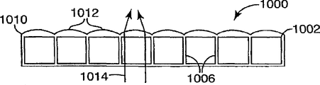
Grooved drum plate can have the surface of other type.In another example, schematically illustrated as Figure 10, the ground floor 1002 of grooved drum plate 1000 has upper surface 1010, and this upper surface is included as a series of lens 1012 that the light 1014 that passes grooved drum plate provides focal power.Lens 1012 can but and nonessential have and web member 1006 between the spacing equal widths.Lens 1012 can be the biconvex lens that extends on the whole width of plate 1000.These class lens are particularly suitable for using the plate of expressing technique manufacturing.Also can use other method (for example, molded) to make lens 1012.
Grooved drum plate can be used for supporting other optical layers of display.For example, one or more other layers can be attached on the grooved drum plate.Provide following example so that some possible combinations of other layer and grooved drum plate to be shown.Figure 11 A shows the optical layers structure 1100 with grooved drum plate 1101, and reflecting polarizing layer 1110 is attached to the upper surface on the upper strata 1102 of grooved drum plate.Can use the attached reflecting polarizing layer 1110 of bonding agent (for example, clear binder or light diffusive adhesive).Prismatic brightness layer 1112 is attachable to the top of reflecting polarizing layer 1110.In some exemplary embodiments, may need at least some light to enter brightness enhancement layer 1112 by air interface or by formed interface from the low-refraction to the high index of refraction.Therefore, low-index material (for example, fluorinated polymer) layer can be disposed in brightness enhancement layer 1112 and between the next-door neighbour's layer below the brightness enhancement layer 1112.
In other exemplary embodiments, can air gap be set in brightness enhancement layer 1112 with between the layer below the brightness enhancement layer 1112.A kind of method that air gap is set is, in brightness enhancement layer 1112 be arranged on apparent surface's the one or both of the layer below the brightness enhancement layer 1112 structure is set.In the illustrated embodiment, the lower surface 1114 of brightness enhancement layer 1112 is configured with the projection 1116 that contacts with adjacent layer.Therefore, form space 1118 between projection 1116, consequently, the light that enters brightness enhancement layer 1112 from the position between the projection 1116 has passed air interface really.In other embodiments, can omit reflecting polarizing layer 1110, and prismatic brightness layer 1112 directly is attached on the grooved drum plate 1101.In certain embodiments, grooved drum plate 1101 can provide the light diffusion, perhaps, independent diffusion layer can be set, this diffusion layer (for example) is attached to the lower floor 1104 of channeled layer 1101, or be attached on the ground floor 1102 of channeled layer 1101, promptly be positioned at (i) channeled layer and (ii) between reflecting polarizing layer 1110 and/or the prismatic brightness layer 1112.
Can use other method to form the space, thereby provide air interface for the light that enters brightness enhancement layer.For example, brightness enhancement layer can have smooth lower surface, and its adjacent layer is configured with projection.These methods and other method be in U.S. Patent No. 7,010, discusses to some extent among 212 people such as () Emmons.Any embodiment that can adjust the grooved drum plate of this paper discussion provides air interface to be used to the light that enters brightness enhancement layer.
Film is attached to the order of grooved drum plate 1101 can be different.For example, reflecting polarizing layer 1110 can be attached to the prism surface of brightness enhancement layer 1112, and brightness enhancement layer 1112 is attached to grooved drum plate 1101.Figure 11 B schematically shows this structure 1120.The prism surface of optical thin film and brightness enhancement layer be attached in U.S. Patent No. 6,846, further describe among 089 (people such as Stevenson).
Schematically show such exemplary embodiment among Figure 12 A: in the structure shown in this embodiment 1200, one or more pieces films are attached to the lower floor of grooved drum plate.In this embodiment, reflective polarizer 1210 is attached to the second layer 1204 of grooved drum plate 1201, and prismatic brightness layer 1212 is attached to the ground floor of grooved drum plate 1201.Optionally diffusion layer 1214 is attachable on the lower surface of reflective polarizer 1210.In other embodiments, grooved drum plate self can provide some diffusions.In this case, may need grooved drum plate 1201 also to make the light depolarization that passes reflective polarizer 1210 indistinctively.
Figure 12 B schematically shows another exemplary embodiment 1220 of the grooved drum plate 1201 that is attached to the light control film structure.In this embodiment 1220, diffusion layer 1222 is attached to grooved drum plate 1201.Middle layer 1224 is arranged on the diffusion layer 1222, and prismatic brightness layer 1226 is arranged on the middle layer 1224.Diffusion layer 1222 can be (for example) acrylic foam tape: after middle layer 1224 was pushed this foam tape, this foam tape can deform, thereby formed the sunk area of placing the middle layer.Middle layer 1224 can have optical function: for example, middle layer 1224 can be reflective polarizer films.The example of other suitable light control film structure that can together use with grooved drum plate has more detailed description in U.S. Patent Application Publication No.2006/0082699 people such as () Gehlsen.
Except molded, also there is other method of making grooved drum plate.A kind of method is that the ridge that will be provided with web member is attached to another sheet optical thin film.Figure 13 A and 13B schematically show this method.Ridge 1302 has cross member 1304 and web member 1306 arrays.Web member 1306 can be an one with cross member 1304.For example, can be by molded or extrude and form ridge 1302.Ridge 1302 can be by making with the material type identical materials of above-mentioned grooved drum plate.Therefore, ridge 1302 can be made by optical clear or light-scattering material.
Optical thin film 1310 is attached to web member 1306.This optical thin film can be the film of any adequate types.For example, film 1310 can be prismatic brightness film, diffusion barrier, reflective polarizer films, enhanced diffusion film, lens coating, absorptive polarizers, matt film etc.In addition, optical thin film 1310 can only be a transparent membrane.In addition, optical thin film can also be attached to the below of the cross member 1304 of ridge 1302.
Figure 13 B shows the optical thin film 1310 that is attached to web member 1306.Can use any suitable method that film 1310 is attached to web member.For example, bonding agent can be put on the top 1314 of the lower surface 1312 and/or the web member 1306 of film 1310, with after web member top 1314 contacts, this bonding agent be solidified at lower surface 1312.Another kind method is that film 1310 and web member 1306 form by polymeric material, in this method, before each polymeric material is crosslinked fully, film 1310 are contacted with web member 1306, and be subsequently that film 1310 and web member 1306 is crosslinked together.Can use the other method, for example, optical thin film be contacted with the polymkeric substance of fusing, to form combining between optical thin film and the groove.In another approach, can heat (extruding the back), carry out laminated after a while again groove.In addition, can also adopt the groove of coextrusion, wherein groove forms matrix (non-adhesive type, structure member) by a kind of material and at the another kind of material (adhesive type material) of top coextrusion.
After attach film 1310, film 1310 and the ridge 1302 common plates that form with groove 1316.
In another embodiment, schematically illustrated as Figure 14 A (element is separated) and 14B (element is attached together), ridge 1402 has web member group 1406a, 1406b respectively in the both sides of cross member 1404.Two optical thin film 1410a, 1410b can be attached to web member group 1406a, 1406b separately.Optical thin film 1406a, 1406b can be the optical thin film of any required type, for example, and transparent membrane, diffusion barrier, prismatic brightness film, reflective polarizer films etc.
In film 1410a, 1410b at least one is attached to after the ridge 1402, film 1410a and 1410b and the ridge 1402 common plates with groove 1416 that form.
Figure 15 schematically shows a specific embodiment of optical thin film structure 1500, and optical thin film structure 1500 comprises the ridge 1502 of Figure 14 B shown type.In this embodiment, diffusion layer 1510 is attached to down web member 1506b, and prismatic brightness layer 1512 is attached to upper connector.Reflecting polarizing layer 1514 can be attached to the structured side of prismatic brightness layer 1512 alternatively.
Figure 16 schematically shows another representative configuration 1600, and wherein reflective polarizer 1514 is arranged between diffusion layer 1510 and the ridge 1502.
Two-layer another kind of method attached together is to use the layer that can interconnect.For example, can use and be similar to the used bindiny mechanism of sealed food preservation bag this two-layerly mechanically is connected to each other.Figure 17 shows the exemplary embodiment of this mechanism, and it shows the part of upper strata 1702 and lower floor 1704.Each layer 1702,1704 has the interconnecting component 1706,1708 at another layer respectively.When two layers 1702,1704 were pressed together, interconnecting component 1706,1708 was buckled together and forms web member.Can (for example) use expressing technique formation to have layer 1702, the layer 1704 of interconnecting component 1706,1708 respectively.Interconnecting component 1706 can but and nonessentially have a shape identical with interconnecting component 1708.
No matter whether ridge is used to connect the upper and lower, can use partial continuous formula technology to form grooved drum plate.Film that can the formation the upper and lower are used and optional ridge unreel separately and are attached together.In case these layers are attached to each other, and the fluted product of gained is just harder relatively.The plate of monolithic can be formed by continuous fluted product cutting.
Grooved drum plate can be used for improving the heat management situation in the display system (for example, television indicator or monitor).Figure 18 schematically shows the exemplary embodiment of display system 1800, and display system 1800 comprises one or more light sources 1802, grooved drum plate 1804, optical control layer structure 1806 and display panel 1808.Cooling medium can flow along the groove of grooved drum plate 1804, thereby reduces the running temperature of display system.Cooling medium can be air, in certain embodiments, and the groove that air can only be flowed through and be vertically oriented owing to natural convection.In further embodiments, can use the circulate coolant device to force the cooling medium groove of flowing through.For example, can use fan 1810 to force the groove of air through grooved drum plate 1804.In other embodiments, can force transparent fluid (for example, the water) groove of flowing through by pump.
Should be appreciated that there are many possible not isostructures within the scope of the present invention that wherein different layers are arranged with different order to the top from the bottom of structure, perhaps are arranged in the diverse location with respect to ridge.
Should not be considered as the present invention and be confined to above-mentioned each instantiation, contain all aspects of the present invention that offer some clarification on as appended claims and be interpreted as the present invention.For those skilled in the art in the invention, after reading instructions of the present invention, be applicable to that various altered form of the present invention, the technology that is equal to and multiple structure will be conspicuous.For example, in display device, also can use the self-supporting optical thin film, be the attached grooved drum plate that other optical layers is arranged on this optical thin film next door.And display can use a plurality of grooved drum plates.The groove of a plurality of grooved drum plates can be arranged as parallel to each other, and perhaps, the groove of a plate can be orientated with the groove of another grooved drum plate not parallel.Claims are intended to contain these modification and device.
Claims (19)
1. light control unit that uses between display panel and backlight, described light control unit have towards the display panel side of described display panel with towards the source backlight of described backlight, and described unit comprises:
Channeled layer, it comprise first optical control layer, with the described first optical control layer almost parallel and spatially isolated cross member and first web member structure that becomes one with described cross member, described first web member is attached to described first optical control layer.
2. unit according to claim 1, wherein said first optical control layer comprises one in diffusion layer, brightness enhancement layer and the reflecting polarizing layer.
3. unit according to claim 1 also comprises second optical control layer that is attached to described channeled layer.
4. unit according to claim 3, wherein second web member structure makes described second optical control layer be connected with described cross member.
5. unit according to claim 3, wherein said second optical control layer is connected to described first optical control layer, makes described first optical control layer between described cross member and described second optical control layer.
6. unit according to claim 1, wherein said first web member is arranged on the display panel side of described cross member and from described cross member and begins to extend, described unit also comprises second web member on the source backlight that is arranged on described cross member, described second web member begins to extend from described cross member, and described unit also comprises second optical control layer that is attached to described second web member.
7. display system comprises:
Light source;
Display panel; And
Be arranged on the optical control layer structure between described light source and the described display panel, make described light source throw light on to described display panel by described optical control layer structure, described optical control layer structure comprises that grooved drum plate, described grooved drum plate comprise towards the anterior layer of described display panel, towards the back layer of described light source and connect described anterior layer and a plurality of web members of described back layer.
8. system according to claim 7, wherein said optical control layer structure comprises at least one in reflecting polarizing layer, diffusion layer and the prismatic brightness layer.
9. system according to claim 7, at least a portion of wherein said grooved drum plate is formed by diffusion material.
10. system according to claim 7, wherein said optical control layer structure also comprises at least one in diffusion layer, reflecting polarizing layer and the prismatic brightness layer.
11. system according to claim 7, at least one in wherein said anterior layer and the described back layer comprises first optical control layer.
12. system according to claim 11, wherein said first optical control layer comprises at least one in prismatic brightness layer, diffusion layer and the reflecting polarizing layer.
13. system according to claim 11, wherein said web member comprises first web member and second web member, described first web member is attached to cross member and is connected with described anterior layer, described second web member is attached to described cross member and is connected with described back layer, described first optical control layer is attached to one in described first web member and described second web member, and described system also comprises second optical control layer on another person who is connected in described first web member and described second web member.
14. system according to claim 7 also comprises the controller of connection, described controller is used to control the shown image of described display panel.
15. system according to claim 7, wherein said display panel comprises LCD (LCD).
16. system according to claim 7 also comprises the circulate coolant device, described circulate coolant device is used to force the heat eliminating medium groove of described grooved drum plate of flowing through.
17. system according to claim 16, wherein said circulate coolant device is a fan, and described cooling medium is an air.
18. system according to claim 7, the groove of wherein said grooved drum plate is vertically arranged, allow to form airflow through wherein natural convection passage.
19. system according to claim 7, wherein said web member comprises first web member that is attached to described anterior layer and is attached to second web member, described first web member and the described second web member interlocking of described back layer.
Applications Claiming Priority (2)
| Application Number | Priority Date | Filing Date | Title |
|---|---|---|---|
| US11/276,442 | 2006-02-28 | ||
| US11/276,442 US20070203267A1 (en) | 2006-02-28 | 2006-02-28 | Optical display with fluted optical plate |
Publications (1)
| Publication Number | Publication Date |
|---|---|
| CN101390002A true CN101390002A (en) | 2009-03-18 |
Family
ID=38444883
Family Applications (1)
| Application Number | Title | Priority Date | Filing Date |
|---|---|---|---|
| CNA2007800061516A Pending CN101390002A (en) | 2006-02-28 | 2007-02-23 | Optical display with fluted optical plate |
Country Status (7)
| Country | Link |
|---|---|
| US (1) | US20070203267A1 (en) |
| JP (1) | JP2009528571A (en) |
| KR (1) | KR20080109732A (en) |
| CN (1) | CN101390002A (en) |
| DE (1) | DE112007000458T5 (en) |
| TW (1) | TW200741309A (en) |
| WO (1) | WO2007100742A1 (en) |
Cited By (2)
| Publication number | Priority date | Publication date | Assignee | Title |
|---|---|---|---|---|
| CN107077062A (en) * | 2014-11-04 | 2017-08-18 | 日本轻金属株式会社 | Epidermis supporting frame and manufacture method |
| CN113250589A (en) * | 2017-10-12 | 2021-08-13 | 苹果公司 | Light-transmitting panel with active component |
Families Citing this family (12)
| Publication number | Priority date | Publication date | Assignee | Title |
|---|---|---|---|---|
| KR100719658B1 (en) * | 2005-11-17 | 2007-05-17 | 삼성에스디아이 주식회사 | Portable display device |
| CN101408628A (en) * | 2007-10-10 | 2009-04-15 | 群康科技(深圳)有限公司 | Diffusion chip and manufacturing process thereof and backlight module unit and LCD device |
| WO2011123795A1 (en) | 2010-04-02 | 2011-10-06 | Battelle Memorial Institute | Methods for associating or dissociating guest materials with a metal organic framework, systems for associating or dissociating guest materials within a series of metal organic frameworks, and gas separation assemblies |
| SE534994C2 (en) | 2010-07-28 | 2012-03-06 | Anders Rensmo | light plate |
| EP2823216B1 (en) | 2012-03-05 | 2022-04-27 | LMPG Inc. | Light emitting panel assemblies and light guides therefor |
| TWI667498B (en) | 2014-10-23 | 2019-08-01 | 美商康寧公司 | A light diffusing component and a method of manufacturing a light diffusing component |
| US10705266B2 (en) * | 2015-08-05 | 2020-07-07 | 3M Innovative Properties Company | Optical diffusing film laminate and method of making |
| US10480752B2 (en) | 2016-02-27 | 2019-11-19 | Svv Technology Innovations, Inc. | Structurally reinforced illumination panels and a method of making the same |
| KR102519932B1 (en) * | 2017-10-19 | 2023-04-11 | 삼성전자주식회사 | Display apparatus |
| KR102399433B1 (en) * | 2017-12-06 | 2022-05-19 | 엘지디스플레이 주식회사 | Backlight unit and display device having the same |
| CN110095929A (en) * | 2018-01-29 | 2019-08-06 | 精工爱普生株式会社 | Projector |
| US20220350063A1 (en) * | 2021-04-29 | 2022-11-03 | Meta Platforms Technologies, Llc | High surface quality optical film |
Family Cites Families (63)
| Publication number | Priority date | Publication date | Assignee | Title |
|---|---|---|---|---|
| US2841904A (en) * | 1957-01-29 | 1958-07-08 | Theodore M Jablon | Slide mountings |
| US3655263A (en) * | 1970-04-20 | 1972-04-11 | Mark Hoffman | Light diffusion device |
| US4415509A (en) * | 1981-07-07 | 1983-11-15 | Mitsubishi Rayon Company, Ltd. | Acrylic laminated diffuser panel having high light-diffusing property and process for preparing same |
| US4830899A (en) * | 1986-07-04 | 1989-05-16 | Nissen Chemical Industry Co., Ltd. | Light reflection material, its manufacture and application |
| US4904079A (en) * | 1986-08-13 | 1990-02-27 | Sharp Kabushiki Kaisha | Liquid crystal display device for overhead projector |
| US5379139A (en) * | 1986-08-20 | 1995-01-03 | Semiconductor Energy Laboratory Co., Ltd. | Liquid crystal device and method for manufacturing same with spacers formed by photolithography |
| JPS6363020A (en) * | 1986-09-04 | 1988-03-19 | Semiconductor Energy Lab Co Ltd | Preparation of liquid crystal electro-optic device |
| JPS63118718A (en) * | 1986-11-07 | 1988-05-23 | Toyota Motor Corp | Production of liquid crystal display element |
| US5112722A (en) * | 1989-04-12 | 1992-05-12 | Nippon Sheet Glass Co., Ltd. | Method of producing light control plate which induces scattering of light at different angles |
| US6153289A (en) * | 1992-04-29 | 2000-11-28 | Murray; Nicholas J. | Laminates |
| TW289095B (en) * | 1993-01-11 | 1996-10-21 | ||
| US5428468A (en) * | 1993-11-05 | 1995-06-27 | Alliedsignal Inc. | Illumination system employing an array of microprisms |
| US5396350A (en) * | 1993-11-05 | 1995-03-07 | Alliedsignal Inc. | Backlighting apparatus employing an array of microprisms |
| US5882774A (en) * | 1993-12-21 | 1999-03-16 | Minnesota Mining And Manufacturing Company | Optical film |
| US5751388A (en) * | 1995-04-07 | 1998-05-12 | Honeywell Inc. | High efficiency polarized display |
| KR100407101B1 (en) * | 1995-10-12 | 2004-02-18 | 인터내셔널 비지네스 머신즈 코포레이션 | Light-transmitting material, planar light source device and liquid crystal display device |
| DE69636109T2 (en) * | 1995-11-06 | 2006-09-21 | Seiko Epson Corp. | Lighting device, including liquid crystal display and electronic device |
| US6104454A (en) * | 1995-11-22 | 2000-08-15 | Hitachi, Ltd | Liquid crystal display |
| US5825543A (en) * | 1996-02-29 | 1998-10-20 | Minnesota Mining And Manufacturing Company | Diffusely reflecting polarizing element including a first birefringent phase and a second phase |
| US5867316A (en) * | 1996-02-29 | 1999-02-02 | Minnesota Mining And Manufacturing Company | Multilayer film having a continuous and disperse phase |
| JP3669541B2 (en) * | 1997-06-12 | 2005-07-06 | 株式会社エンプラス | Sidelight type surface light source device |
| US6497946B1 (en) * | 1997-10-24 | 2002-12-24 | 3M Innovative Properties Company | Diffuse reflective articles |
| US6343865B1 (en) * | 1998-02-17 | 2002-02-05 | Dai Nippon Printing Co., Ltd. | Non-glare film, polarizing device and display device |
| US6282821B1 (en) * | 1998-06-25 | 2001-09-04 | 3M Innovative Properties Company | Low-loss face diffuser films for backlit signage and methods for using same |
| US6352759B2 (en) * | 1998-08-20 | 2002-03-05 | Physical Optics Corporation | Non-lambertian glass diffuser and method of making |
| US6160663A (en) * | 1998-10-01 | 2000-12-12 | 3M Innovative Properties Company | Film confined to a frame having relative anisotropic expansion characteristics |
| US6827456B2 (en) * | 1999-02-23 | 2004-12-07 | Solid State Opto Limited | Transreflectors, transreflector systems and displays and methods of making transreflectors |
| KR20000060073A (en) * | 1999-03-11 | 2000-10-16 | 구본준 | Backlight of a liquid crystal display device |
| WO2000060384A1 (en) * | 1999-03-31 | 2000-10-12 | Daicel Chemical Industries, Ltd. | Light scattering sheet, light scattering composite sheet, and liquid crystal display |
| JP3594868B2 (en) * | 1999-04-26 | 2004-12-02 | 日東電工株式会社 | Laminated polarizing plate and liquid crystal display |
| US6122103A (en) * | 1999-06-22 | 2000-09-19 | Moxtech | Broadband wire grid polarizer for the visible spectrum |
| KR100673796B1 (en) * | 1999-09-09 | 2007-01-24 | 키모토 컴파니 리미티드 | Transparent hard coat film |
| JP3882428B2 (en) * | 1999-10-29 | 2007-02-14 | セイコーエプソン株式会社 | Manufacturing method of liquid crystal device |
| WO2001058991A1 (en) * | 2000-02-10 | 2001-08-16 | Teijin Limited | Polyester film composite, light diffuser plate, and utilization thereof |
| WO2001079340A1 (en) * | 2000-04-13 | 2001-10-25 | 3M Innovative Properties Company | Light stable articles |
| US6917399B2 (en) * | 2001-02-22 | 2005-07-12 | 3M Innovative Properties Company | Optical bodies containing cholesteric liquid crystal material and methods of manufacture |
| US7173677B2 (en) * | 2001-04-12 | 2007-02-06 | Rohm Co., Ltd. | Back light unit for liquid crystal display device and method for manufacturing the unit |
| US6642974B2 (en) * | 2001-05-29 | 2003-11-04 | Chun-Chi Liao | Assembly of backlight mask |
| US6642977B2 (en) * | 2001-06-20 | 2003-11-04 | 3M Innovative Properties Company | Liquid crystal displays with repositionable front polarizers |
| JP3850241B2 (en) * | 2001-07-19 | 2006-11-29 | シャープ株式会社 | LIGHTING DEVICE AND LIQUID CRYSTAL DISPLAY DEVICE USING THE SAME |
| TWI293704B (en) * | 2002-02-19 | 2008-02-21 | Au Optronics Corp | |
| US6636363B2 (en) * | 2002-03-11 | 2003-10-21 | Eastman Kodak Company | Bulk complex polymer lens light diffuser |
| US7010212B2 (en) * | 2002-05-28 | 2006-03-07 | 3M Innovative Properties Company | Multifunctional optical assembly |
| JP3952168B2 (en) * | 2002-06-11 | 2007-08-01 | 富士通株式会社 | Electronic device, liquid crystal display device and light guide plate |
| KR20040009902A (en) * | 2002-07-26 | 2004-01-31 | 삼성전자주식회사 | Back light assembly using the same and liquid crystal display device |
| KR100878206B1 (en) * | 2002-08-13 | 2009-01-13 | 삼성전자주식회사 | Optical sheet and back light assembly using the same and liquid crystal display device using the same |
| US6842204B1 (en) * | 2002-09-06 | 2005-01-11 | Rockwell Collins | Color display system for NVIS Class A compatibility |
| DE10245580B4 (en) * | 2002-09-27 | 2006-06-01 | Siemens Ag | Device for generating an image |
| US7236217B2 (en) * | 2003-01-16 | 2007-06-26 | 3M Innovative Properties Company | Package of optical films with zero-gap bond outside viewing area |
| CN101441292A (en) * | 2003-02-28 | 2009-05-27 | 夏普株式会社 | Surface radiating conversion element, an LCD and a method for fabricating the surface radiating conversion element |
| KR20040090667A (en) * | 2003-04-18 | 2004-10-26 | 삼성전기주식회사 | light unit for displaying |
| US7041365B2 (en) * | 2003-05-12 | 2006-05-09 | 3M Innovative Properties Company | Static dissipative optical construction |
| US6846089B2 (en) * | 2003-05-16 | 2005-01-25 | 3M Innovative Properties Company | Method for stacking surface structured optical films |
| JP2005044744A (en) * | 2003-07-25 | 2005-02-17 | Clariant Internatl Ltd | Surface light source device |
| US7413336B2 (en) * | 2003-08-29 | 2008-08-19 | 3M Innovative Properties Company | Adhesive stacking for multiple optical films |
| TWM254613U (en) * | 2003-11-14 | 2005-01-01 | Litemax Electronics Inc | Backlight module of liquid crystal display |
| EP1636683A4 (en) * | 2003-12-15 | 2007-08-22 | Schott Corp | Touch control assembly |
| TWI272421B (en) * | 2004-05-13 | 2007-02-01 | Au Optronics Corp | Backlight unit and liquid crystal display utilizing the same |
| JP4305850B2 (en) * | 2004-05-24 | 2009-07-29 | 株式会社 日立ディスプレイズ | Backlight device and display device |
| US7165856B2 (en) * | 2005-02-22 | 2007-01-23 | Chunghwa Picture Tubes, Ltd. | Light-duide plate and backlight module |
| KR20060105346A (en) * | 2005-04-04 | 2006-10-11 | 삼성전자주식회사 | Back light unit and liquid crystal display apparatus employing the same |
| US20070236413A1 (en) * | 2006-03-29 | 2007-10-11 | 3M Innovative Properties Company | Fluted optical plate with internal light sources and systems using same |
| US7766531B2 (en) * | 2006-03-29 | 2010-08-03 | 3M Innovative Properties Company | Edge-lit optical display with fluted optical plate |
-
2006
- 2006-02-28 US US11/276,442 patent/US20070203267A1/en not_active Abandoned
-
2007
- 2007-02-23 CN CNA2007800061516A patent/CN101390002A/en active Pending
- 2007-02-23 JP JP2008557320A patent/JP2009528571A/en not_active Withdrawn
- 2007-02-23 WO PCT/US2007/004867 patent/WO2007100742A1/en active Application Filing
- 2007-02-23 KR KR1020087020626A patent/KR20080109732A/en not_active Application Discontinuation
- 2007-02-23 DE DE112007000458T patent/DE112007000458T5/en not_active Withdrawn
- 2007-02-27 TW TW096106734A patent/TW200741309A/en unknown
Cited By (2)
| Publication number | Priority date | Publication date | Assignee | Title |
|---|---|---|---|---|
| CN107077062A (en) * | 2014-11-04 | 2017-08-18 | 日本轻金属株式会社 | Epidermis supporting frame and manufacture method |
| CN113250589A (en) * | 2017-10-12 | 2021-08-13 | 苹果公司 | Light-transmitting panel with active component |
Also Published As
| Publication number | Publication date |
|---|---|
| KR20080109732A (en) | 2008-12-17 |
| US20070203267A1 (en) | 2007-08-30 |
| WO2007100742A1 (en) | 2007-09-07 |
| JP2009528571A (en) | 2009-08-06 |
| DE112007000458T5 (en) | 2009-01-22 |
| TW200741309A (en) | 2007-11-01 |
Similar Documents
| Publication | Publication Date | Title |
|---|---|---|
| CN101390002A (en) | Optical display with fluted optical plate | |
| CN102590907B (en) | Diffuse multilayer optical assembly | |
| CN101310198B (en) | Multi-function enhancement film | |
| US7766531B2 (en) | Edge-lit optical display with fluted optical plate | |
| EP2023166B1 (en) | Optical Element Comprising Restrained Asymmetrical Diffuser | |
| CN101080661B (en) | Liquid crystal displays with laminated diffuser plates | |
| KR101396001B1 (en) | Backlight suitable for display devices | |
| US20070159699A1 (en) | Diffuser plate with higher light diffusion efficiency and brightness | |
| US20090201441A1 (en) | Tensioned optical element having crimping frame and spring | |
| US20060290253A1 (en) | Enhanced Diffusing Plates, Films and Backlights | |
| CN101251680A (en) | Optical diffuser film and light assembly | |
| CN101535880A (en) | Back-lit displays with high illumination uniformity | |
| CN101535878A (en) | Back-lit displays with high illumination uniformity | |
| CN101251679B (en) | Optical device with self-supporting film assembly | |
| JP2010015133A (en) | Optical diffuser film with linear domain of varying diffusion | |
| JP2012003279A (en) | Liquid crystal display with laminate diffuser plate | |
| CN101535879A (en) | Back-lit displays with high illumination uniformity | |
| CN113296312A (en) | Display device | |
| CN102165359A (en) | Optical sheet and composite sheet with MOIRE FRINGE, and backlight assembly having the same | |
| JP2010044270A (en) | Light diffusion plate, optical sheet, back light unit and display device | |
| JP5256723B2 (en) | Light diffusion plate, optical sheet, backlight unit, and display device | |
| JP2010044268A (en) | Light diffusion plate, optical sheet, back light unit and display device | |
| JP5120210B2 (en) | Light diffusion plate, optical sheet, backlight unit, and display device | |
| CN101285962A (en) | Optical elements covering member, backlight and liquid crystal display device | |
| KR20080099404A (en) | Manufacturing method of light-diffusing film |
Legal Events
| Date | Code | Title | Description |
|---|---|---|---|
| C06 | Publication | ||
| PB01 | Publication | ||
| C10 | Entry into substantive examination | ||
| SE01 | Entry into force of request for substantive examination | ||
| AD01 | Patent right deemed abandoned |
Effective date of abandoning: 20090318 |
|
| C20 | Patent right or utility model deemed to be abandoned or is abandoned |