JP2009512467A - Analytical support means with lancet and test room - Google Patents
Analytical support means with lancet and test room Download PDFInfo
- Publication number
- JP2009512467A JP2009512467A JP2008535945A JP2008535945A JP2009512467A JP 2009512467 A JP2009512467 A JP 2009512467A JP 2008535945 A JP2008535945 A JP 2008535945A JP 2008535945 A JP2008535945 A JP 2008535945A JP 2009512467 A JP2009512467 A JP 2009512467A
- Authority
- JP
- Japan
- Prior art keywords
- lancet
- protective cap
- needle
- tip
- analysis
- Prior art date
- Legal status (The legal status is an assumption and is not a legal conclusion. Google has not performed a legal analysis and makes no representation as to the accuracy of the status listed.)
- Pending
Links
Images


Classifications
-
- A—HUMAN NECESSITIES
- A61—MEDICAL OR VETERINARY SCIENCE; HYGIENE
- A61B—DIAGNOSIS; SURGERY; IDENTIFICATION
- A61B5/00—Measuring for diagnostic purposes; Identification of persons
- A61B5/145—Measuring characteristics of blood in vivo, e.g. gas concentration, pH value; Measuring characteristics of body fluids or tissues, e.g. interstitial fluid, cerebral tissue
- A61B5/1468—Measuring characteristics of blood in vivo, e.g. gas concentration, pH value; Measuring characteristics of body fluids or tissues, e.g. interstitial fluid, cerebral tissue using chemical or electrochemical methods, e.g. by polarographic means
- A61B5/1477—Measuring characteristics of blood in vivo, e.g. gas concentration, pH value; Measuring characteristics of body fluids or tissues, e.g. interstitial fluid, cerebral tissue using chemical or electrochemical methods, e.g. by polarographic means non-invasive
-
- A—HUMAN NECESSITIES
- A61—MEDICAL OR VETERINARY SCIENCE; HYGIENE
- A61B—DIAGNOSIS; SURGERY; IDENTIFICATION
- A61B5/00—Measuring for diagnostic purposes; Identification of persons
- A61B5/145—Measuring characteristics of blood in vivo, e.g. gas concentration, pH value; Measuring characteristics of body fluids or tissues, e.g. interstitial fluid, cerebral tissue
- A61B5/14532—Measuring characteristics of blood in vivo, e.g. gas concentration, pH value; Measuring characteristics of body fluids or tissues, e.g. interstitial fluid, cerebral tissue for measuring glucose, e.g. by tissue impedance measurement
-
- A—HUMAN NECESSITIES
- A61—MEDICAL OR VETERINARY SCIENCE; HYGIENE
- A61B—DIAGNOSIS; SURGERY; IDENTIFICATION
- A61B5/00—Measuring for diagnostic purposes; Identification of persons
- A61B5/15—Devices for taking samples of blood
- A61B5/150007—Details
- A61B5/150015—Source of blood
- A61B5/150022—Source of blood for capillary blood or interstitial fluid
-
- A—HUMAN NECESSITIES
- A61—MEDICAL OR VETERINARY SCIENCE; HYGIENE
- A61B—DIAGNOSIS; SURGERY; IDENTIFICATION
- A61B5/00—Measuring for diagnostic purposes; Identification of persons
- A61B5/15—Devices for taking samples of blood
- A61B5/150007—Details
- A61B5/150206—Construction or design features not otherwise provided for; manufacturing or production; packages; sterilisation of piercing element, piercing device or sampling device
- A61B5/150213—Venting means
-
- A—HUMAN NECESSITIES
- A61—MEDICAL OR VETERINARY SCIENCE; HYGIENE
- A61B—DIAGNOSIS; SURGERY; IDENTIFICATION
- A61B5/00—Measuring for diagnostic purposes; Identification of persons
- A61B5/15—Devices for taking samples of blood
- A61B5/150007—Details
- A61B5/150206—Construction or design features not otherwise provided for; manufacturing or production; packages; sterilisation of piercing element, piercing device or sampling device
- A61B5/150274—Manufacture or production processes or steps for blood sampling devices
- A61B5/150282—Manufacture or production processes or steps for blood sampling devices for piercing elements, e.g. blade, lancet, canula, needle
-
- A—HUMAN NECESSITIES
- A61—MEDICAL OR VETERINARY SCIENCE; HYGIENE
- A61B—DIAGNOSIS; SURGERY; IDENTIFICATION
- A61B5/00—Measuring for diagnostic purposes; Identification of persons
- A61B5/15—Devices for taking samples of blood
- A61B5/150007—Details
- A61B5/150358—Strips for collecting blood, e.g. absorbent
-
- A—HUMAN NECESSITIES
- A61—MEDICAL OR VETERINARY SCIENCE; HYGIENE
- A61B—DIAGNOSIS; SURGERY; IDENTIFICATION
- A61B5/00—Measuring for diagnostic purposes; Identification of persons
- A61B5/15—Devices for taking samples of blood
- A61B5/150007—Details
- A61B5/150374—Details of piercing elements or protective means for preventing accidental injuries by such piercing elements
- A61B5/150381—Design of piercing elements
- A61B5/150412—Pointed piercing elements, e.g. needles, lancets for piercing the skin
- A61B5/150435—Specific design of proximal end
-
- A—HUMAN NECESSITIES
- A61—MEDICAL OR VETERINARY SCIENCE; HYGIENE
- A61B—DIAGNOSIS; SURGERY; IDENTIFICATION
- A61B5/00—Measuring for diagnostic purposes; Identification of persons
- A61B5/15—Devices for taking samples of blood
- A61B5/150007—Details
- A61B5/150374—Details of piercing elements or protective means for preventing accidental injuries by such piercing elements
- A61B5/150381—Design of piercing elements
- A61B5/150503—Single-ended needles
- A61B5/150511—Details of construction of shaft
-
- A—HUMAN NECESSITIES
- A61—MEDICAL OR VETERINARY SCIENCE; HYGIENE
- A61B—DIAGNOSIS; SURGERY; IDENTIFICATION
- A61B5/00—Measuring for diagnostic purposes; Identification of persons
- A61B5/15—Devices for taking samples of blood
- A61B5/150007—Details
- A61B5/150374—Details of piercing elements or protective means for preventing accidental injuries by such piercing elements
- A61B5/150534—Design of protective means for piercing elements for preventing accidental needle sticks, e.g. shields, caps, protectors, axially extensible sleeves, pivotable protective sleeves
- A61B5/150572—Pierceable protectors, e.g. shields, caps, sleeves or films, e.g. for hygienic purposes
-
- A—HUMAN NECESSITIES
- A61—MEDICAL OR VETERINARY SCIENCE; HYGIENE
- A61B—DIAGNOSIS; SURGERY; IDENTIFICATION
- A61B5/00—Measuring for diagnostic purposes; Identification of persons
- A61B5/15—Devices for taking samples of blood
- A61B5/151—Devices specially adapted for taking samples of capillary blood, e.g. by lancets, needles or blades
- A61B5/15101—Details
- A61B5/15103—Piercing procedure
- A61B5/15107—Piercing being assisted by a triggering mechanism
- A61B5/15113—Manually triggered, i.e. the triggering requires a deliberate action by the user such as pressing a drive button
-
- A—HUMAN NECESSITIES
- A61—MEDICAL OR VETERINARY SCIENCE; HYGIENE
- A61B—DIAGNOSIS; SURGERY; IDENTIFICATION
- A61B5/00—Measuring for diagnostic purposes; Identification of persons
- A61B5/15—Devices for taking samples of blood
- A61B5/151—Devices specially adapted for taking samples of capillary blood, e.g. by lancets, needles or blades
- A61B5/15186—Devices loaded with a single lancet, i.e. a single lancet with or without a casing is loaded into a reusable drive device and then discarded after use; drive devices reloadable for multiple use
- A61B5/15188—Constructional features of reusable driving devices
- A61B5/1519—Constructional features of reusable driving devices comprising driving means, e.g. a spring, for propelling the piercing unit
-
- A—HUMAN NECESSITIES
- A61—MEDICAL OR VETERINARY SCIENCE; HYGIENE
- A61B—DIAGNOSIS; SURGERY; IDENTIFICATION
- A61B5/00—Measuring for diagnostic purposes; Identification of persons
- A61B5/15—Devices for taking samples of blood
- A61B5/151—Devices specially adapted for taking samples of capillary blood, e.g. by lancets, needles or blades
- A61B5/15186—Devices loaded with a single lancet, i.e. a single lancet with or without a casing is loaded into a reusable drive device and then discarded after use; drive devices reloadable for multiple use
- A61B5/15188—Constructional features of reusable driving devices
- A61B5/15192—Constructional features of reusable driving devices comprising driving means, e.g. a spring, for retracting the lancet unit into the driving device housing
- A61B5/15194—Constructional features of reusable driving devices comprising driving means, e.g. a spring, for retracting the lancet unit into the driving device housing fully automatically retracted, i.e. the retraction does not require a deliberate action by the user, e.g. by terminating the contact with the patient's skin
-
- A—HUMAN NECESSITIES
- A61—MEDICAL OR VETERINARY SCIENCE; HYGIENE
- A61B—DIAGNOSIS; SURGERY; IDENTIFICATION
- A61B5/00—Measuring for diagnostic purposes; Identification of persons
- A61B5/15—Devices for taking samples of blood
- A61B5/157—Devices characterised by integrated means for measuring characteristics of blood
-
- A—HUMAN NECESSITIES
- A61—MEDICAL OR VETERINARY SCIENCE; HYGIENE
- A61B—DIAGNOSIS; SURGERY; IDENTIFICATION
- A61B2562/00—Details of sensors; Constructional details of sensor housings or probes; Accessories for sensors
- A61B2562/02—Details of sensors specially adapted for in-vivo measurements
- A61B2562/0295—Strip shaped analyte sensors for apparatus classified in A61B5/145 or A61B5/157
-
- A—HUMAN NECESSITIES
- A61—MEDICAL OR VETERINARY SCIENCE; HYGIENE
- A61B—DIAGNOSIS; SURGERY; IDENTIFICATION
- A61B5/00—Measuring for diagnostic purposes; Identification of persons
- A61B5/145—Measuring characteristics of blood in vivo, e.g. gas concentration, pH value; Measuring characteristics of body fluids or tissues, e.g. interstitial fluid, cerebral tissue
- A61B5/1486—Measuring characteristics of blood in vivo, e.g. gas concentration, pH value; Measuring characteristics of body fluids or tissues, e.g. interstitial fluid, cerebral tissue using enzyme electrodes, e.g. with immobilised oxidase
- A61B5/14865—Measuring characteristics of blood in vivo, e.g. gas concentration, pH value; Measuring characteristics of body fluids or tissues, e.g. interstitial fluid, cerebral tissue using enzyme electrodes, e.g. with immobilised oxidase invasive, e.g. introduced into the body by a catheter or needle or using implanted sensors
Landscapes
- Health & Medical Sciences (AREA)
- Life Sciences & Earth Sciences (AREA)
- Engineering & Computer Science (AREA)
- Physics & Mathematics (AREA)
- Animal Behavior & Ethology (AREA)
- Veterinary Medicine (AREA)
- Biophysics (AREA)
- Biomedical Technology (AREA)
- Heart & Thoracic Surgery (AREA)
- Medical Informatics (AREA)
- Molecular Biology (AREA)
- Surgery (AREA)
- Pathology (AREA)
- General Health & Medical Sciences (AREA)
- Public Health (AREA)
- Hematology (AREA)
- Manufacturing & Machinery (AREA)
- Optics & Photonics (AREA)
- Chemical & Material Sciences (AREA)
- Chemical Kinetics & Catalysis (AREA)
- General Chemical & Material Sciences (AREA)
- Emergency Medicine (AREA)
- Dermatology (AREA)
- Measurement Of The Respiration, Hearing Ability, Form, And Blood Characteristics Of Living Organisms (AREA)
- Investigating Or Analysing Biological Materials (AREA)
Abstract
Description
本発明は、滅菌状態に防護されたランセットと、分析テスト室とを含んでいる分析補助手段に関する。さらに本発明は、このような分析補助手段を製造する方法に関する。 The present invention relates to an analytical aid means comprising a sterilized protected lancet and an analytical test chamber. Furthermore, the present invention relates to a method for manufacturing such an analytical auxiliary means.
血液試料の検査は、病理状態を早期かつ確実に臨床診断で発見し、根拠のある的確な身体状態のコントロールをすることを可能にする。医療上の血液診断のためには、常に、検査されるべき個体の血液試料を得ることが前提条件となる。診療所や開業医のもとでは、通常、静脈穿刺によって、検査されるべき人物の数ミリリットルの血液を分析用として得ており、それにより多数の研究室テストを実施できるようにしているが、1つのパラメータに目標をはっきりと定めている個々の分析のためには、一般的には、数マイクロリットルから1マイクロリットル以下の血液があれば十分である。このように少ない血液量は、高いコストのかかる痛みの強い静脈穿刺を必要としない。むしろその場合、血液取得のために、検査されるべき人物のたとえば指頭腹面や耳たぶなどに滅菌した鋭いランセットを用いて皮膚を刺し、そのようにして数マイクロリットルまたはそれ以下の血液を分析用に取得するだけで足りる。特にこの方式は、血液試料の分析を血液取得の直後に実施することができる場合に適している。 Examination of blood samples makes it possible to detect pathological conditions early and reliably in clinical diagnosis, and to control the appropriate physical condition with evidence. For medical blood diagnostics, it is always a prerequisite to obtain a blood sample of the individual to be examined. Under clinics and practitioners, a few milliliters of blood from a person to be examined is usually obtained for analysis by venipuncture, which allows many laboratory tests to be performed. For individual analyzes that are specifically targeted to one parameter, it is generally sufficient to have a few microliters to 1 microliter or less of blood. Such a small blood volume does not require costly and painful venipuncture. Rather, in that case, to obtain blood, the skin should be punctured with a sterilized sharp lancet on the person to be examined, such as the abdominal surface of the finger or the earlobe, and so a few microliters or less of blood for analysis Just getting it is enough. This method is particularly suitable when a blood sample can be analyzed immediately after blood acquisition.
特にいわゆる「ホームモニタリング」の分野では、すなわち、特に糖尿病患者によって血中グルコース濃度の管理のために1日に何度も定期的に行われるべき血液取得のために医療の素人が自分で簡単な血液分析を行うような場面では、できるだけ痛みが少なく再現可能な血液取得を可能にする、ランセットおよびこれに適合した器具(いわゆる血液採取器具、血液ランセット装置、あるいは−以下に掲げるような−穿刺補助具)が提供されている。さらに、穿刺補助具を備えるランセットの使用は、自分の身体に穿刺をするときの心理的な抵抗感を下げることが意図されており、このことは、特に糖尿病を患っていて定期的な血中グルコーステストを受けざるを得ない子供にとって特別な意義がある。 Especially in the field of so-called “home monitoring”, that is, medical profession is easy for himself to obtain blood which should be performed regularly many times a day, especially for diabetics to manage blood glucose levels. In situations where blood analysis is performed, a lancet and a device suitable for it (so-called blood collection device, blood lancet device, or -as described below) that enables reproducible blood acquisition with as little pain as possible Tools) are provided. In addition, the use of a lancet with a puncture aid is intended to reduce the psychological resistance when puncturing one's body, which is particularly common in people with diabetes who have regular blood flow. Of particular significance to children who are forced to take a glucose test.
ランセットと穿刺補助具の例として、市販されている器具(穿刺補助具)およびランセットであるBayer AG社のGlucolet(登録商標)とRoche Diagnostics GmbH社のSoftclix(登録商標)を挙げておく。このようなランセットおよび器具(穿刺補助具)は、たとえば国際公開第98/48695号パンフレット、欧州特許出願公開第0565970号明細書、米国特許第4,442,836号明細書、米国特許第5,554,166号明細書などの対象となっている。 Examples of lancets and puncture aids include commercially available instruments (puncture aids) and lancets such as Bayer AG's Glucolet (registered trademark) and Roche Diagnostics GmbH's Softclix (registered trademark). Such lancets and instruments (puncture aids) are disclosed, for example, in WO 98/48695, EP 0 565 970, US Pat. No. 4,442,836, US Pat. 554,166 specification and the like.
自分の手で行う血糖測定(いわゆる「ホームモニタリング」)は、今日、世界中に普及している糖尿病コントロールの手法である。たとえばAccu−Chek Sensor(Roche Diagnostics社)などの従来技術における血糖器具は測定器具で構成されており、これにテスト部材(テストテープ、センサ)が挿入される。テストテープを、あらかじめ穿刺補助具によって指頭腹面やその他の身体部位から取得された血液滴と接触させる。数多くのシステムコンポーネント(ランセット、穿刺補助具、テストテープ、測定器具)は広いスペースを必要とし、比較的複雑な取扱がなされる。最近では統合度がいっそう高く、それによって取り扱いがより簡単なシステムもある。これには、たとえばAccuChek Compact(Roche Diagnostics社)、Glucometer Dex(Bayer Diagnostics社)、Soft−Sense(Medisense社)などが含まれる。前者の2つのシステムでは、テストテープが測定器具にマガジン収納されており、測定のために提供される。 Blood glucose measurement (so-called “home monitoring”) performed by one's hand is a method of diabetes control that is widely used all over the world today. For example, a blood glucose device in the prior art such as Accu-Chek Sensor (Roche Diagnostics) is composed of a measuring device, into which a test member (test tape, sensor) is inserted. A test tape is brought into contact with a blood drop previously obtained from the abdominal surface of a fingertip or other body part by a puncture assisting tool. Many system components (lancets, puncture aids, test tapes, measuring instruments) require a large amount of space and are relatively complicated to handle. Some systems are more integrated and are easier to handle. This includes, for example, AccuChek Compact (Roche Diagnostics), Glucometer Dex (Bayer Diagnostics), Soft-Sense (Medisense). In the former two systems, a test tape is stored in a measuring instrument in a magazine and provided for measurement.
たとえば複数の機能ないし機能部材を単一の分析補助手段(使い捨て)へ統合することによって、いっそうの小型化のステップを実現することができる。穿刺プロセスと、テストテープ上でのセンサによる分析物濃度検出とを適切に組み合わせることで、たとえば操作手順を明らかに簡素化することができる。これについて従来技術には次のような例がある。 For example, a further miniaturization step can be realized by integrating a plurality of functions or function members into a single analysis assisting means (disposable). By appropriately combining the puncture process and the analyte concentration detection by the sensor on the test tape, for example, the operation procedure can be clearly simplified. In this regard, there are the following examples in the prior art.
欧州特許出願公告第0199484号明細書(Audio Bionics社)は、器具側で作動させる一体化されたランセットを備える分析補助手段(「ディスポーザブル」;略して「ディスポ」)を記載している(たとえば図9参照)。専用のスプリング支持部("spring-mounted lance means")によって、ランセットは穿刺後に再び引き戻される。このディスポはいわゆる芯材手段("wick means")を含んでおり、これにより、試料液が身体表面から分析領域へ、すなわち光学的に評価可能なテスト区画へと誘導される。 European Patent Application Publication No. 0199484 (Audio Bionics) describes an analytical aid (“disposable”; “dispos” for short) with an integrated lancet that is actuated on the instrument side (eg FIG. 9). The lancet is pulled back after puncture by a dedicated spring support ("spring-mounted lance means"). This disposable contains so-called “wick means”, which lead the sample liquid from the body surface to the analysis area, ie to the optically evaluable test compartment.
米国特許第6,143,164号明細書(E.Heller&Comp.社)には、身体の開口部(たとえば皮膚の小さい針穴や切開部)をつくり、次いで体液をセンサまで移送して、そこで分析物の存在に関して検査が行われる方法が記載されている。米国特許第6,143,164号明細書はそのために、ランセット装置がセンサのテストテープの上に取り付けられた分析補助手段を開示している。身体の開口部から本来のセンサの検証部材までの試料液の移送は、たとえば同じく「芯材手段」を通じて行われ、あるいは毛管間隙/毛管通路を通じて行われる。 In US Pat. No. 6,143,164 (E. Heller & Comp.), A body opening (eg, a small needle hole or incision in the skin) is made and then body fluid is transferred to the sensor where it is analyzed. It describes how the test is performed for the presence of objects. For this purpose, US Pat. No. 6,143,164 discloses analytical aid means in which a lancet device is mounted on the test tape of the sensor. The sample liquid is transferred from the opening of the body to the verification member of the original sensor, for example, through the “core member means” or through the capillary gap / capillary passage.
米国特許第4,627,445号明細書には、ランセットの取出しと器具への血液の取込みのためにただ1つの開口部しか有していない統合システムが記載されている。しかしこの発明では、ランセット先端部と開口部の両方を滅菌状態に閉鎖する滅菌防護は利用されない。 U.S. Pat. No. 4,627,445 describes an integrated system that has only one opening for removal of the lancet and blood into the instrument. However, this invention does not utilize sterilization protection that closes both the lancet tip and the opening in a sterilized state.
さらにテスト部材の統合は、ランセットのために新たな防護部材が開発されるという結果につながっている。統合システムにおけるランセットの使用は、手動式で挿入されるランセットの場合とは違った手順進行で行われるので、ランセットを滅菌状態に、しかしそれにもかかわらず常時利用可能に保つための手段を見出さなくてはならなかった。手動式で挿入されるランセットの場合に通常行われるように、利用者が使用前に滅菌防護部を取り外すことは、統合システムではもはや必要ない。これに関して従来技術では次のような解決の提案がなされている。 Furthermore, the integration of the test members has led to the development of new protective members for the lancet. The use of a lancet in an integrated system takes place in a different procedure than that of a manually inserted lancet, so that no means are found to keep the lancet sterile but nevertheless available at all times. I didn't. It is no longer necessary in an integrated system for the user to remove the sterilization guard before use, as is usually the case with manually inserted lancets. In this regard, the following solutions have been proposed in the prior art.
米国特許第2003153939号明細書は、先端部を穿刺プロセスのときまで滅菌状態に保ち、引き続いて衛生的な保管がなされるように作用するランセットないしそのランセット先端部のための防護メカニズムを記載している。この防護メカニズムは穿刺プロセスのときに突き破られ、ランセットは穿刺プロセスの後に再び防護体で取り囲まれるので、使用済みランセットによる周囲の汚染が生じないようになっている。 U.S. Patent No. 2003153939 describes a lancet or protective mechanism for the lancet tip that acts to keep the tip sterile until the time of the puncture process and subsequent hygienic storage. Yes. This protective mechanism is breached during the puncturing process, and the lancet is again surrounded by a protective body after the puncturing process, so that surrounding contamination by the used lancet does not occur.
米国特許第2003050573号明細書は、ランセット先端部を穿刺プロセスのときまで滅菌状態に保つ、統合システムにおけるランセット防護に関するものである。この場合、滅菌されたランセット先端部は、血液試料が採取される開口部とは場所的に切り離された出口開口部から外に出る。 US2003050573 relates to lancet protection in an integrated system that keeps the lancet tip sterile until the time of the puncture process. In this case, the sterilized lancet tip exits through an exit opening that is separated from the opening from which the blood sample is collected.
公知のディスポの1つの欠点は、患者が介入することを必要としない、ランセット滅菌防護、テスト室の滅菌防護、血液移送のできるだけ短い経路といった種々の機能の統合がなされていないことである。たとえば単一の側面についての解決法はあるが、これらすべての要求事項を組み合わせるための解決法は存在しない。たとえば従来技術ではハウジング開口部を封止するときに封止材料が刺し通され、封止材料は変位可能ではないので、試料を採取するために追加の開口部をつくらなくてはならない。それにより、滅菌防護を用いて作動する統合システムのために、穿刺プロセスと血液採取との空間的な分離を意図する複雑な構造が必要となる。そのために患者は、血液採取プロセスへ能動的に介入することを強いられる。このことは快適性の大幅な損失を意味しており、特に、視力の弱い患者にとっては非常に厄介である。 One disadvantage of known disposables is that they do not integrate various functions such as lancet sterilization protection, test room sterilization protection, and the shortest possible path of blood transfer that do not require patient intervention. For example, there is a solution for a single aspect, but there is no solution for combining all these requirements. For example, in the prior art, the sealing material is pierced when sealing the housing opening, and the sealing material is not displaceable, so an additional opening must be made to collect the sample. Thereby, a complex structure intended for spatial separation of the puncture process and blood collection is required for an integrated system operating with sterilization protection. This forces the patient to actively intervene in the blood collection process. This represents a significant loss of comfort and is particularly troublesome for patients with poor vision.
そこで本発明の課題は、従来技術の欠点を取り除くことにある。特に本発明の課題は、従来技術の欠点を有していない分析補助手段(または、この同義語として:「ディスポーザブル」、略して「ディスポ」)を提供することである。きわめて限定的には、本発明のディスポにより、使用期限までの期間全体を通じてのランセット滅菌状態の確保が、同時にランセットとテスト部材とを統合したうえで保証されるのが望ましい。このとき、ディスポ開口部からテスト部材までの、分析されるべき液体のできるだけ短い経路が保証されているのが望ましい。患者にとってこのシステムは、穿刺後に患者がそれ以上血液取得に関わらなくてよい、高い操作快適性を有しているのがよい。 An object of the present invention is to eliminate the drawbacks of the prior art. In particular, it is an object of the present invention to provide an analysis aid (or as a synonym: “disposable”, “dispos” for short) that does not have the disadvantages of the prior art. In a very limited way, it is desirable that the disposable according to the invention ensures that the lancet sterilization is ensured throughout the period up to the expiration date, simultaneously integrating the lancet and the test member. At this time, it is desirable to ensure as short a path as possible of the liquid to be analyzed from the disposable opening to the test member. For the patient, the system should have high operational comfort so that the patient may not be involved in further blood collection after puncture.
さらに本発明の課題は、少なくともランセット針先端部が未使用状態のときに使用直前まで滅菌状態すなわち無菌状態に保たれるとともに、使用済み状態では衛生的に保管することができる、ランセットを備えた分析補助手段を提供することにある。理想的には、利用者が衛生的な保管のために別途の措置を講じることなく、この課題が解決されるのが望ましい。さらに、ランセットによる、特に使用済みのランセットによる意図しないけがから、利用者が守られるべきである。最後に、血液取得の個所から血液検査の個所までの簡単な試料移送が可能であるのが好ましい。 A further object of the present invention is to provide a lancet that can be kept in a sterilized state, that is, a sterilized state until just before use, at least when the tip of the lancet needle is unused, and can be stored hygienically in a used state It is to provide an analysis aid. Ideally, this issue should be solved without the user taking any additional steps for hygienic storage. In addition, users should be protected from unintended injuries from lancets, especially from used lancets. Finally, it is preferable that simple sample transfer from the blood acquisition location to the blood test location is possible.
これらの課題は、独立請求項に特徴が記載されている本発明の対象物によって解決される。好ましい実施形態は、従属請求項の対象となっている。 These objects are solved by the subject matter of the invention characterized in the independent claims. Preferred embodiments are the subject of the dependent claims.
本発明の第1の対象物は、ランセットを含んでいる分析補助手段である。ランセットは、構成要素として、先端部と防護キャップとを備えるランセット針を有していることが好ましく、この防護キャップはランセット針を少なくとも先端部の領域で完全に取り囲む。このときランセット針は防護キャップに対して相対的に変位可能である。このとき防護キャップは、刺し通し可能であるとともにランセット針の先端部が埋設される、さまざまな材料でできていてよい。さらに分析補助手段は、試薬系を備えた検証部材を含んでいる室からなる分析テスト部材を含んでいる。この室は開口部を有しており、ランセットは穿刺プロセスのときにこの開口部を通って運動する。この開口部はランセット針の防護キャップによって閉止される。 The first object of the present invention is an analysis auxiliary means including a lancet. The lancet preferably has as its components a lancet needle comprising a tip and a protective cap, the protective cap completely surrounding the lancet needle at least in the region of the tip. At this time, the lancet needle can be displaced relative to the protective cap. At this time, the protective cap may be made of various materials that can be pierced and in which the tip of the lancet needle is embedded. The analysis assisting means further includes an analysis test member comprising a chamber containing a verification member provided with a reagent system. This chamber has an opening through which the lancet moves during the puncture process. This opening is closed by a protective cap of the lancet needle.
最後に、このような分析補助手段を製造する方法も、本発明の対象物である。 Finally, a method for producing such an analysis aid is also an object of the present invention.
本発明による解決法は、穿刺と、穿刺によってできた傷口からテスト部材までの血液移送と、分析物の検証という3つの機能が1つのボディに集約されている、特に小型化されたディスポからなるものである。 The solution according to the invention consists of a particularly miniaturized disposable, in which three functions are integrated into one body: puncture, blood transfer from the wound made by puncture to the test member, and verification of the analyte. Is.
本発明による分析補助手段の本体は、好ましくは中空室を備え、その外側形状が好ましくはハウジング開口部を閉止する目的のために相応に適合化されている、剛性の高いプラスチック体でできている。このプラスチックにランセット針が埋設されて、その先端部が好ましくは本体の前端から突き出さないようになっている。したがって、この本体は防護キャップとも呼ぶことができる。本体は、1つの好ましい実施形態ではウェブを有しており、このウェブは針を本体に固定し、穿刺運動中にこれを案内する役目を果たす。しかしながら、穿刺運動のときの摩擦力を最低限に抑えるために、針の大半の部分は本体と結合されていないのが好ましい。針と防護キャップとの間の接触面は最低限に抑えられ、適当に前処理され、たとえばシリコン処理されるのが好ましい。 The body of the analysis aid according to the invention is preferably made of a rigid plastic body with a hollow chamber, whose outer shape is preferably adapted accordingly for the purpose of closing the housing opening. . A lancet needle is embedded in the plastic so that the tip thereof preferably does not protrude from the front end of the main body. Therefore, this body can also be called a protective cap. The body has a web in one preferred embodiment, which serves to secure the needle to the body and guide it during the lancing movement. However, in order to minimize the frictional force during the puncturing movement, it is preferred that most of the needle is not coupled to the body. The contact surface between the needle and the protective cap is minimized and is preferably pretreated, for example siliconized.
分析補助手段はハウジングからなっており、その中に防護キャップを備えるランセット針ならびにテスト部材がある。任意選択で、電気化学測定をする場合には、少なくとも1つの電極がテスト室内にある。ハウジングは、1つの好ましい実施形態では、2つのハウジング部分からなっている。これらのハウジング部分は射出成形法によりさまざまなプラスチックから製作することができる。全部を網羅するのではないポリマーの選択肢として、ポリエステル、ポリカーボネート、ポリ塩化ビニル、ポリメチルメタクリレート、コポリエステル、ならびにこれらの混合物がある。テスト部材の光学評価をする場合には、ハウジングの一部が透明な材料でできている。 The analysis assisting means comprises a housing in which there is a lancet needle with a protective cap and a test member. Optionally, for electrochemical measurements, at least one electrode is in the test chamber. The housing, in one preferred embodiment, consists of two housing parts. These housing parts can be made from various plastics by injection molding. Polymer options that are not exhaustive include polyesters, polycarbonates, polyvinyl chloride, polymethylmethacrylates, copolyesters, and mixtures thereof. For optical evaluation of the test member, a part of the housing is made of a transparent material.
本発明によるランセットは1回だけ使用するように構想されているのが好ましく、したがってワンウェイ血液ランセットまたは使い捨て血液ランセットとも呼ぶことができる。本発明のランセットは先端部を備える針(ランセット針)を含んでいる。針は通常、長さが数ミリメートル(mm)から数センチメートル(cm)であり、長尺状の形態を有している。典型的には、針は円筒状の形態を有している。この針形状が格別にうまく製造可能だからである。しかしながら、これと異なる形状を付与された針形状も可能である。針の先端領域は、ランセットを用途に従って使用するときに組織内へ刺し込まれる針先端部を含んでいる。したがってランセット針の先端部は、穿刺されるべき個体の皮膚と接触することになり、場合によりこれを傷つけ、そのようにして体液、特に血液や組織間液の流出を引き起すランセットの部分である。 The lancet according to the invention is preferably envisaged to be used only once and can therefore also be referred to as a one-way blood lancet or a disposable blood lancet. The lancet of the present invention includes a needle having a tip (lancet needle). Needles are typically a few millimeters (mm) to a few centimeters (cm) long and have an elongated form. Typically, the needle has a cylindrical form. This is because this needle shape can be manufactured particularly well. However, a needle shape with a different shape is also possible. The needle tip region includes the needle tip that is pierced into the tissue when the lancet is used according to the application. Thus, the tip of the lancet needle is the part of the lancet that will come into contact with the skin of the individual to be punctured, possibly damaging it and thus causing the outflow of body fluids, particularly blood and interstitial fluid .
ランセット針の先端部は、たとえば一般に穿刺針の場合に当てはまるような回転対称であってよい。しかしながら、針先端部に1つまたは複数の研削面を取り付けると好ましいことが判明している。この場合に生じる、針の長軸に対して傾いた、先端部で終わっているエッジ部は、穿刺のときに先鋭な切れ刃としての役目を果たし、研削されていない針を用いた場合よりも少ない痛みで穿刺プロセスを進行させる。 The tip of the lancet needle may be rotationally symmetric as is typically the case for puncture needles, for example. However, it has been found preferable to attach one or more grinding surfaces to the needle tip. In this case, the edge part that is inclined with respect to the long axis of the needle and ends at the tip part serves as a sharp cutting edge at the time of puncture, and is more than when an unground needle is used. Proceed the puncture process with less pain.
本発明によるランセットのランセット針は、穿刺プロセス中、加工段階中、または場合により生じるその他の負荷中に変形することなく機械的負荷に耐えるのに十分に硬い材料から製作されている。さらにこの材料は、穿刺プロセス中に粒子がこぼれたり剥離したりしない性質を備えていなくてはならない。最後に針材料は、針先端部が十分に尖っており、針先端部のエッジを場合により十分に鋭く研削することができるように加工可能でなくてはならない。ランセット針によく適した材料はとりわけ金属であり、その中でも特に貴金属である。ただし、液位計およびカウンター電極としてのランセットの特性を放棄するのであれば、シリコン、セラミック、またはプラスチックからなる針も考えられる。貴金属の針が格別に好ましい。 The lancet needle of the lancet according to the present invention is made of a material that is sufficiently hard to withstand mechanical loads without deformation during the puncturing process, during the processing stage, or during other loads that may occur. In addition, the material must have the property that the particles do not spill or flake off during the puncture process. Finally, the needle material must be machined so that the needle tip is sufficiently sharp and the edge of the needle tip can be ground sufficiently sharp in some cases. Materials that are well suited for lancet needles are especially metals, among which noble metals are particularly suitable. However, a needle made of silicon, ceramic, or plastic is also conceivable if the characteristics of the lancet as a liquid level meter and counter electrode are to be discarded. Precious metal needles are particularly preferred.
本発明によると、1つの実施形態では少なくとも本発明によるランセットのランセット針の先端部は防護キャップで取り囲まれている。その際に重要なのは、防護キャップがランセット針の先端部の領域で、ランセット先端部にとって突き破ることが可能な材料でできていることである。防護キャップが弾性材料で製作されていると、防護キャップはランセット先端部をいっそう好ましい仕方で全面的に取り囲む。したがってランセット先端部は周囲から遮断される。さまざまな実施形態で防護キャップを全面的または部分的に形成することができる防護キャップの弾性材料は、柔らかく、変形可能であり、ランセット針によってその先端部で突き破ることが可能であり、先端部を傷つけることがないという特徴を有している。非弾性的な防護キャップの場合、ランセット先端部は、ランセット先端部と防護キャップ壁部との間に中空スペースができるように防護キャップで取り囲まれるのが好ましい。このとき防護キャップ材料の壁厚は、この場合にも、突き破られたときにランセット先端部の研削エッジの変形や磨減が生じないように設計される。 According to the invention, in one embodiment at least the tip of the lancet needle of the lancet according to the invention is surrounded by a protective cap. What is important here is that the protective cap is made of a material that can penetrate the lancet tip in the region of the tip of the lancet needle. If the protective cap is made of an elastic material, the protective cap completely surrounds the lancet tip in a more favorable manner. Therefore, the lancet tip is blocked from the surroundings. The elastic material of the protective cap, which can form the protective cap in whole or in part in various embodiments, is soft and deformable and can be pierced at its tip by a lancet needle. It has the feature of not hurting. In the case of an inelastic protective cap, the lancet tip is preferably surrounded by a protective cap so that there is a hollow space between the lancet tip and the protective cap wall. At this time, the wall thickness of the protective cap material is designed so that the grinding edge at the tip of the lancet is not deformed or worn when it is pierced.
穿刺プロセスのとき、ランセット針はその長軸に沿って防護キャップに対して相対的に運動し、その先端部で防護キャップを通ってハウジングから外に出て、そのようにして血液取得のために、検査されるべき個体の皮膚へ突き刺すことができる。 During the puncture process, the lancet needle moves relative to the protective cap along its long axis and exits the housing through the protective cap at its tip, thus for blood collection Can pierce the skin of the individual to be examined.
ランセット針の先端部を全面的に取り囲む防護キャップの弾性材料は、その使用前に、好ましくは使用の直前まで、ランセット針先端部の滅菌状態を保証する。したがって弾性材料は、ランセット針の未使用状態のとき、菌の出入りに対して菌を通さないようになっている。さらに、弾性材料はランセット針先端部の機械的な防護部であり、そのようにして、ランセット針先端部に当たって意図しないけがをすることを防止する。 The elastic material of the protective cap that completely surrounds the tip of the lancet needle ensures sterility of the tip of the lancet needle before its use, preferably until just before use. Therefore, when the lancet needle is not used, the elastic material prevents the bacteria from entering and exiting the bacteria. Furthermore, the elastic material is a mechanical protection for the tip of the lancet needle, thus preventing unintentional injury from hitting the tip of the lancet needle.
本発明の防護キャップの弾性材料としては、合成ゴム、生ゴム、シリコン、エラストマー、および特に熱可塑性エラストマーなどが好適であることが判明している。これらは本発明にとって重要な特性を有しており、すなわち柔らかく、変形可能であり、先端部を傷つけることなくランセット針によって突き破ることが可能であり、未使用のランセット針先端部の周りを密閉して閉鎖する。さらにこれらの材料は、ランセットを多くの個数で大量生産することを可能にする射出成形プロセスに使用することができる。 As the elastic material of the protective cap of the present invention, it has been found that synthetic rubber, raw rubber, silicon, elastomer, and particularly thermoplastic elastomer are suitable. These have important properties for the present invention, i.e. they are soft and deformable, can be pierced by a lancet needle without damaging the tip, and seal around the tip of an unused lancet needle. And close. Furthermore, these materials can be used in an injection molding process that allows mass production of large numbers of lancets.
弾性プラスチックまたは熱可塑性樹脂または熱可塑性ゴムとも呼ばれる熱可塑性エラストマーは、理想的な場合、エラストマーの使用特性と熱可塑性樹脂の加工特性との組み合わせを有している。熱可塑性エラストマーは、たとえばスチロール−オリゴブロック−コポリマー(いわゆるTPE−S)、熱可塑性ポリオレフィン(TPE−O)、熱可塑性ポリウレタン(TPE−U)、熱可塑性コポリエステル(TPE−E)、および熱可塑性コポリアミド(TPE−A)である。特に、たとえばスチロール−エチレン−ブチレン−スチロール−ポリマー(SEBSポリマー、たとえばEvode Plastics社のEvoprene(登録商標)やGummiwerk Kraiburg GmbH社のThermolast K)をベースとする熱可塑性エラストマーが好適であることが判明している。 Thermoplastic elastomers, also called elastic plastics or thermoplastic resins or thermoplastic rubbers, ideally have a combination of elastomeric usage characteristics and thermoplastic resin processing characteristics. Thermoplastic elastomers are, for example, styrene-oligoblock copolymers (so-called TPE-S), thermoplastic polyolefins (TPE-O), thermoplastic polyurethanes (TPE-U), thermoplastic copolyesters (TPE-E), and thermoplastics. Copolyamide (TPE-A). In particular, thermoplastic elastomers based on, for example, styrene-ethylene-butylene-styrol-polymers (SEBS polymers, such as Evoprene® from Evode Plastics or Thermolast K from Gummiwerk Kraiburg GmbH) have proved suitable. ing.
穿刺プロセス中に、ランセット針は防護キャップに対して相対的に運動する。このとき防護キャップは、穿刺補助具または穿刺器具によってその位置で固定されるのが好ましい。ランセット針はその駆動の目的のために特別に成形されていてよく、たとえば先端部と反対側の端部に針頭部を有していてよく、あるいは先端部を取り囲む防護キャップに追加して、穿刺補助具の駆動部材によって把持することができる、さらに別のランセット体ないしランセット保持部を有していてよい。針または追加のランセット保持部の成形は、適当なやり方で、穿刺器具(穿刺補助具)にある相応の駆動装置と相互作用することができる。一般に、このような手段は針の駆動装置と呼ぶことができる。このような駆動装置は、たとえば米国特許出願公告第6,783,537B1号明細書や欧州特許出願公開第1336375号明細書などから、当業者には十分に知られている。 During the puncturing process, the lancet needle moves relative to the protective cap. At this time, the protective cap is preferably fixed at that position by a puncture assisting device or a puncture device. The lancet needle may be specially shaped for its driving purpose, for example it may have a needle head at the end opposite the tip, or it may be added to a protective cap surrounding the tip and punctured. There may be provided another lancet body or lancet holding part which can be held by the driving member of the auxiliary tool. The shaping of the needle or the additional lancet holder can interact in a suitable manner with a corresponding drive on the puncture device (puncture aid). In general, such means can be referred to as a needle drive. Such drive devices are well known to those skilled in the art, for example from US Patent Application Publication No. 6,783,537 B1 and European Patent Application Publication No. 1336375.
弾性材料の安定性を高めるために、たとえばこれを剛性の高い材料と、剛性の高いプラスチック材料と結合することが可能である。このとき弾性材料は、ランセット針の先端部と接触することがない外面で、剛性の高い材料の層により、剛性の高いプラスチックの層により、安定化されていてよい。ランセット防護部をランセット針先端部の領域でのみ弾性材料で製作し、それ以外はランセットの外装を従来式の剛性の高いプラスチックで製作することも可能である。この場合、弾性材料と剛性の高い材料は互いに接着されていてよく、または、二成分射出成形プロセスなどの射出成形プロセスによって互いに結合されていてよい。このときランセット外装の剛性の高い材料は、穿刺プロセス中に弾性材料を機械的に安定化するように作用し、穿刺補助具による穿刺プロセス中に防護キャップの弾性材料の固定を容易にする。剛性の高い材料はテスト部材の一部であってもよく、たとえば国際公開第99/29429号パンフレットに記載されているような毛管間隙テスト部材の一部であってよい。さらに別の実施形態では、防護キャップ全体が剛性の高いプラスチック材料からなっていてよい。 In order to increase the stability of the elastic material, for example, it can be combined with a rigid material and a rigid plastic material. At this time, the elastic material may be stabilized by a layer of high-rigidity material and a layer of high-rigidity plastic on the outer surface that does not contact the tip of the lancet needle. It is also possible to manufacture the lancet protection portion with an elastic material only in the region of the lancet needle tip, and otherwise, the lancet exterior can be manufactured with a conventional high-stiffness plastic. In this case, the elastic material and the rigid material may be bonded together or may be joined together by an injection molding process such as a two-component injection molding process. At this time, the highly rigid material of the lancet exterior acts to mechanically stabilize the elastic material during the puncture process, and facilitates fixing of the elastic material of the protective cap during the puncture process by the puncture assisting device. The stiff material may be part of the test member, for example a capillary gap test member as described in WO 99/29429. In yet another embodiment, the entire protective cap may be made of a rigid plastic material.
患者は穿刺プロセスのときに防護キャップと接触しないか、または部分的にしか接触しない。むしろ患者は指をハウジングの開口部に載せ、この開口部は、駆動装置の側にはなく、かつ測定器具とディスポの結合部の側にないのが好ましい。指を置いてから患者はメカニズムを作動させることができ、このメカニズムが、休止状態から活動状態になって再び休止状態へと戻るランセットの運動を惹起する。このときランセットはその遠位の端部が、すなわち先端部が、短い時間のあいだに開口部を通ってハウジングから外へ出る。ハウジングの中へ戻る途中で、ランセット体に連結された、またはこれと結合された捕捉装置によって、やはり穿刺中にハウジング内にとどまる防護キャップを一緒に引き戻す。 The patient does not contact or only partially contacts the protective cap during the puncture process. Rather, the patient places his finger on the housing opening, which is preferably not on the drive side and not on the measurement instrument / dispo joint. After placing the finger, the patient can activate the mechanism, which triggers the movement of the lancet from resting to active and back to rest. The lancet then has its distal end, i.e. the tip, exiting the housing through the opening for a short period of time. On the way back into the housing, the protective cap, which remains in the housing during puncture, is pulled back together by a capture device connected to or coupled to the lancet body.
測定地点におけるランセットの傷口/穿刺個所からの血液移送は、本発明によると次のような形式で具体化される。すなわち、血液移送は本発明によるディスポの利用者の関与なしに、いわば「自動式に」惹起されるのが好ましい。この目的のために、ディスポは試料液移送をするための手段を有していてよい。この手段は、毛管作用をもつように、たとえば定置の本体にある間隙または通路として、または吸引能力のある基質材料として構成されていると好ましい。これら両方の原理的可能性の組み合わせも可能であり、たとえば、血液がまず毛管通路を介して案内され、吸引能力のある基質材料によって引き取られて、テスト室へと放出されることも可能である。 According to the present invention, blood transfer from the wound / puncture site of the lancet at the measurement point is embodied in the following manner. That is, the blood transfer is preferably triggered “automatically” without the involvement of the user of the disposable according to the invention. For this purpose, the disposable may have means for transferring the sample liquid. This means is preferably configured to have a capillary action, for example as a gap or passage in the stationary body or as a matrix material with suction capability. A combination of both of these principle possibilities is also possible, for example, blood can be first guided through the capillary passage, taken up by the suction-capable substrate material and released into the test chamber .
本発明の意味における吸引能力のある基質材料としては、特に、吸引能力のある不織布、紙、芯材、または織物などが好適であることが判明している。 As a substrate material having a suction capability in the meaning of the present invention, it has been found that a nonwoven fabric, paper, core material, or woven fabric having a suction capability is particularly suitable.
1つの好ましい変形例では、分析補助手段の本体、特にテスト室は、試料液移送のための手段を含んでいる。この手段は室内に挿入された吸引能力のある芯材または(好ましくは)成形された毛管間隙であってよく、同時にランセットの出口開口部としての役目を果たす。それにより、ディスポを血液採取のために変位させなくてすむようにできる。吸入口の幾何学形状は、形成された血液滴をできるだけ容易に捕集して取り込むことができるように、たとえば漏斗または刻み目として構成されている。そうすれば、1マイクロリットルを明らかに下回っていてよい必要な血液量が吸引されるように毛管作用が働く。血液はこのような経路で室内に入ってテスト区画へと至り、そこでテスト薬品と反応し、その際に評価可能な電気信号または変色が生起される。毛管間隙は、射出成形のときにプラスチックに成形することができ、あるいは後からプラスチック体へ刻設することができ、たとえば型押しやフライス削りをすることができる。毛管通路への試料液滴の吸込みは、切欠きによって露出している面が親水化されているとともに、少なくとも毛管移送通路の方向で毛管作用のあるゾーンへじかに接していることによって実現されるのが格別に好ましい。 In one preferred variant, the body of the analysis aid means, in particular the test chamber, includes means for sample liquid transfer. This means can be a suction-capable core inserted into the chamber or (preferably) a shaped capillary gap, and at the same time serves as the outlet opening of the lancet. As a result, the disposable can be dispensed with for blood collection. The geometry of the inlet is configured, for example, as a funnel or notch so that the formed blood drop can be collected and taken up as easily as possible. The capillary action then works so that the necessary blood volume, which can be clearly below 1 microliter, is aspirated. The blood enters the room by such a route and reaches the test compartment where it reacts with the test drug, producing an electrical signal or discoloration that can be evaluated. The capillary gap can be molded into plastic at the time of injection molding or can be engraved into the plastic body later, for example by embossing or milling. The suction of the sample droplet into the capillary passage is realized by making the surface exposed by the notch hydrophilic, and at least in direct contact with the capillarity zone in the direction of the capillary transport passage. Is particularly preferred.
親水性の表面は、この関連では水を引き寄せる面である。血液も含めた水状の試料は、このような表面上でよく広がる。このような面は、特に、境界面でその上にある水滴が鋭角のぬれ角または接触角を形成することによって特徴づけられる。これとは対照的に疎水性の、すなわち水をはじく表面では、水滴と表面の間の境界面に鈍角のぬれ角が形成される。液体を吸い上げる毛管の準備態勢は、液体による通路表面の湿潤可能性にともなって変化する。これは水状の試料については、表面張力が水の表面張力に近いか(72mN/m)、もしくはこの値を上回る材料で毛管を製作するのがよいことを意味している。 A hydrophilic surface is a surface that draws water in this context. Watery samples including blood spread well on such surfaces. Such a surface is characterized in particular by the fact that the water drops above it at the interface form an acute wetting angle or contact angle. In contrast, a hydrophobic surface, i.e. a water repellent surface, forms an obtuse wetting angle at the interface between the water droplet and the surface. The readiness of the capillary to suck up the liquid changes with the possibility of wetting of the passage surface by the liquid. This means that for water samples, the capillary should be made of a material whose surface tension is close to that of water (72 mN / m) or above this value.
水状の試料を迅速に吸い上げる、毛管を構成するための十分に親水性の材料は、たとえばガラス、金属、またはセラミックである。しかしテスト支持体で使用するには、これらの材料は重大な欠点をいくつか有しているのであまり適していない。これは、たとえばガラスやセラミックの場合における破損の危険、あるいは数多くの金属における時間にともなう表面特性の変化である。したがって通常、テスト部材の製作にはプラスチックフィルムまたはプラスチック成形部品が使用される。このとき使用するプラスチックは、45mN/mの表面張力をほとんど超えていないのが通常である。相対的に見てもっとも親水性のプラスチック、たとえばポリメチルメタクリレート(PMMA)やポリアミド(PA)を用いても、(吸引をするにしても)非常にゆっくりと吸引をする毛管しか構成することができない。たとえばポリスチロール(PS)、ポリプロピレン(PP)、ポリエチレン(PE)といった疎水性プラスチックからなる毛管は、水状の試料を実質的に吸引しない。以上より、テスト部材の構成材料として使用するためのプラスチックに毛管作用のある通路を親水性で設け、すなわち親水化する必要性が生じる。 Sufficiently hydrophilic materials for constructing capillaries that quickly suck up watery samples are, for example, glass, metal, or ceramic. However, these materials are not well suited for use in test supports because they have some significant drawbacks. This is, for example, the risk of breakage in the case of glass or ceramic, or the change in surface properties with time in many metals. Therefore, plastic films or plastic molded parts are usually used for the production of test members. In general, the plastic used at this time hardly exceeds the surface tension of 45 mN / m. Even the most hydrophilic plastics, such as polymethylmethacrylate (PMMA) and polyamide (PA), can be used to form only very slowly sucked capillaries (even if sucked). . For example, a capillary made of a hydrophobic plastic such as polystyrene (PS), polypropylene (PP), or polyethylene (PE) does not substantially suck a water sample. As described above, there is a need to provide a capillary having a capillary action in a plastic for use as a constituent material of a test member, that is, to make it hydrophilic.
理想的には、毛管通路の表面の親水化は、その製造に親水性材料を用いることによって実現されるが、このような材料は試料液を自ら吸い上げることができず、もしくはさほど吸い上げることができない。これが可能でない場合、疎水性の表面またはごくわずかしか親水性でない表面の親水化は、試料材料に対して不活性で安定した親水性層による適当なコーティングによって実現することができ、たとえば、光反応性の加工が施された親水性ポリマーのプラスチック表面への共有結合によって、または湿潤剤を含有する層の塗布によって、またはゾル・ゲル技術によるナノコンポジットによる表面のコーティングによって実現することができる。さらには、表面の熱処理、物理的処理、または化学処理によって親水性の向上を実現することも可能である。これには、たとえば表面のプラズマ処理なども含まれる。このことは、たとえば高エネルギーの酸素またはその他の分極媒体を用いて行われる。 Ideally, the surface of the capillary passage is hydrophilized by using a hydrophilic material in its manufacture, but such a material cannot or cannot soak up the sample solution by itself. . If this is not possible, hydrophilization of a hydrophobic surface or a surface that is only slightly hydrophilic can be achieved by a suitable coating with a hydrophilic layer that is inert and stable with respect to the sample material, eg photoreaction It can be realized by covalent bonding of hydrophilic polymer to the plastic surface, or by application of a layer containing a wetting agent, or by coating the surface with a nanocomposite by sol-gel technology. Furthermore, hydrophilicity can be improved by heat treatment, physical treatment, or chemical treatment of the surface. This includes, for example, surface plasma treatment. This is done, for example, using high energy oxygen or other polarizing media.
親水化は、酸化アルミニウムの薄い層の使用によって実現されるのがきわめて格別に好ましい。このような層は、たとえば部品素材に金属アルミニウムを真空蒸着し、引き続いて金属を酸化させることによって、テスト部材の所望の構成部品へ直接塗布するか、または、金属フィルムもしくは金属被覆されたプラスチックフィルムの形態で、同じく所望の親水性を得るために酸化させなくてはならないテスト支持構造に対して使用することができる。このとき1から500nmの金属層厚があれば十分である。次いで、酸化形態をつくるために金属層が酸化され、その際には電気化学式の陽極酸化のほか、特に水蒸気の存在下での酸化や、水中での煮沸による酸化が格別に適した手法であることが判明している。こうして得られた酸化物層は、手法に応じて0.1から500nmの間の厚み、好ましくは10から100nmの間の厚みがある。金属層についても酸化物層についても、これ以上の厚みも原則として実際には実現可能であるが、新たな好ましい作用を示すものではない。 Hydrophilization is very particularly preferably achieved by the use of a thin layer of aluminum oxide. Such a layer can be applied directly to the desired component of the test member, for example by vacuum-depositing metallic aluminum on the component material and subsequently oxidizing the metal, or a metal film or a metal-coated plastic film. Can also be used for test support structures that must be oxidized to obtain the desired hydrophilicity. At this time, a metal layer thickness of 1 to 500 nm is sufficient. Next, the metal layer is oxidized to form an oxidized form. In this case, in addition to electrochemical anodic oxidation, oxidation in the presence of water vapor and oxidation by boiling in water are particularly suitable techniques. It has been found. The oxide layer thus obtained has a thickness between 0.1 and 500 nm, preferably between 10 and 100 nm, depending on the procedure. For the metal layer and the oxide layer, a thickness larger than this can be realized in principle, but does not show a new preferable action.
1つの好ましい実施形態では、本発明による分析テスト部材の検証部材は、試料中の目標分析物の検証反応のために必要な一切の試薬および場合により補助物質を含んでいる。検証部材は、試薬または補助物質の一部だけを含んでいてもよい。分析テスト部材の技術、または診断テスト支持体の技術に馴染んでいる当業者にとって、このような試薬や補助剤はたいへんよく周知である。酵素で検証されるべき分析物については、たとえば酵素、酵素基質、指示薬、緩衝塩、不活性充填剤などが検証部材に含まれていてよい。検証部材は1つまたは複数の層で構成されていてよく、場合により不活性の支持体を、好ましくは試薬と接触することがない検証部材の側に含んでいてよい。検証反応によって、本件との関連では色の変化、色の発生、または色の消滅のいずれかであると解されるべき観察可能な変色が起こる特別に好ましいケースについては、適当な方策によって、支持体が検証反応の視覚的または光学的な観察を可能にすることを保証することができる。そのために検証部材の支持体材料はそれ自体が透明であってよく、たとえば透明なプラスチックフィルム、たとえばポリカーボネートフィルムであってよく、あるいは検出側に透明な切欠きを有していてよい。変色につながる検証反応のほか、上述したテスト部材で具体化することができるそれ以外の検証原理、たとえば電気化学式のセンサなども当業者には周知である。 In one preferred embodiment, the verification member of the analytical test member according to the invention contains all reagents and optionally auxiliary substances necessary for the verification reaction of the target analyte in the sample. The verification member may include only a part of the reagent or auxiliary substance. Such reagents and adjuvants are very well known to those skilled in the art of analytical test member technology or diagnostic test support technology. For analytes to be verified with enzymes, for example, enzymes, enzyme substrates, indicators, buffer salts, inert fillers, etc. may be included in the verification member. The verification member may be composed of one or more layers and may optionally include an inert support, preferably on the side of the verification member that does not contact the reagent. Appropriate measures are supported for the particularly favorable case where the validation reaction causes an observable discoloration that should be understood as either a color change, color generation or color disappearance in the context of this case. It can be ensured that the body allows visual or optical observation of the verification reaction. For this purpose, the support material of the verification member may itself be transparent, for example a transparent plastic film, for example a polycarbonate film, or may have a transparent notch on the detection side. In addition to verification reactions that lead to discoloration, other verification principles that can be implemented with the test members described above, such as electrochemical sensors, are well known to those skilled in the art.
分析物の電気化学式の検証では、少なくとも1つの電極がテスト室内にある。この電極はディスポにある接点を介して測定器具と接続されている。このとき、ランセットを第2の電極として利用することができる。ランセットは、ばね接点を介して測定器具と接続されているのが好ましいが、測定器具とランセットとの固定的な接触も可能である。測定は直流電流でも交流電流でも行うことができる。これに加えて、ランセットを液位管理部として利用するという可能性もある。このことは同じく、ランセットの使用後にランセットを測定器具と接続するばね接点によって可能にすることができ、入ってくる液体とランセットが接触すると電流強度変化または電圧変化が生じる。 For verification of the electrochemical formula of the analyte, at least one electrode is in the test chamber. This electrode is connected to the measuring instrument via a contact point in the disposable. At this time, the lancet can be used as the second electrode. The lancet is preferably connected to the measuring instrument via a spring contact, but a fixed contact between the measuring instrument and the lancet is also possible. Measurements can be made with either direct current or alternating current. In addition to this, there is a possibility of using the lancet as a liquid level management unit. This can also be made possible by a spring contact connecting the lancet with the measuring instrument after use of the lancet, where a change in current intensity or voltage occurs when the incoming liquid and the lancet come into contact.
テスト室は、防護キャップを含むランセット先端部を含んでいるだけでなく、必要な検証薬品、および電気化学式の検証の場合にあっては電極も含んでいる。テスト室はそのサイズに関して、テスト液の最小容積が必要とされるように設計されている。これは理想的には1μl以下である。出口開口部を介して液体をテスト室へ最善に移送するために、テスト室の製造には親水性材料を使用するのが好ましい。 The test chamber contains not only the lancet tip that includes the protective cap, but also the required verification chemicals and, in the case of electrochemical verification, electrodes. The test chamber is designed such that a minimum volume of test fluid is required with respect to its size. This is ideally less than 1 μl. In order to best transfer the liquid to the test chamber through the outlet opening, it is preferred to use a hydrophilic material in the manufacture of the test chamber.
テスト室はさまざまな幾何学形態を有することができる。たとえば室は立方体または直方体であってよい。あるいは、室は円形または楕円形の半球の形態をとることもできる。室は少なくとも1つの開口部を有しており、この開口部を通ってランセットが作動時に外へ出る。使用前の休止状態にあるとき、この開口部は、ランセット先端部を取り囲む防護キャップによって閉止されている。ランセットが作動した後、室内への毛管作用を得るために、室の別の換気部が必要になる。このことは室の第2の開口部によって保証することができ、または、ランセットの使用前にはフィルムその他の封止材で閉止されている、ランセット保持部にある換気穴によって保証することができる。室の幾何学形状と容積は、室内の電極の個数に依存して決まる。電極の個数は、補助手段の使い方に準じて決まる。電気化学分析のためには少なくとも1つの電極がテスト室内にあり、ランセットをカウンター電極または基準電極として利用することができる。これをさらに別の電極によって補うことができる。別の電極を付け加えることで、1つを超える分析物を互いに無関係に判定するという可能性が生まれる。このような分析物は、たとえばコレステロール、トリグリセリドなどの血液成分や、凝固因子その他の血液パラメータであってよい。室の容積は100nlから1000nlの間であるが、多数の電極を使用する場合にはこれより大きくてもよい。1つの好ましい実施形態では、容積は300nlから600nlの間であり、特別に好ましくは500nlである。電極ならびにその接点は、導電性プラスチックや金属といった導電性材料でできている。ランセット先端部を電極として利用するときは、電極およびその接点だけでなくランセットも導電性材料でできており、たとえばアルミニウム、鉛、鉄、ガリウム、金、インジウム、イリジウム、炭素(たとえばグラファイト)、コバルト、銅、マグネシウム、ニッケル、ニオブ、オスミウム、パラジウム、白金、水銀(アマルガムとして)、レニウム、ロジウム、セレン、シリコン(たとえばドーピングされた多結晶シリコン)、銀、タンタル、チタン、ウラン、バナジウム、タングステン、スズ、亜鉛、ジルコニウム、これらの混合物ならびに合金でできている。接点と電極は、金、白金、パラジウム、イリジウム、またはこれらの金属の混合物ないし合金を含んでいるのが好ましい。このとき接点は、電極とは異なる材料でできていてもよい。同様に、ランセット先端部はランセット体の残りの部分とは異なる組成を有していてよい。1つの好ましい実施形態は、基準電極としての銀/銀ハロゲン化物の電極、ならびに作業電極としての(たとえばスクリーン印刷された)グラファイト電極である。 The test chamber can have various geometric forms. For example, the chamber may be a cube or a cuboid. Alternatively, the chamber can take the form of a circular or elliptical hemisphere. The chamber has at least one opening through which the lancet exits during operation. When in a rest state before use, the opening is closed by a protective cap that surrounds the lancet tip. After the lancet is activated, a separate ventilation section of the room is required to obtain capillary action into the room. This can be ensured by a second opening in the chamber or by a ventilation hole in the lancet holder that is closed with a film or other sealing material prior to use of the lancet. . The chamber geometry and volume depend on the number of electrodes in the chamber. The number of electrodes is determined according to how the auxiliary means is used. For electrochemical analysis, at least one electrode is in the test chamber and the lancet can be used as a counter electrode or a reference electrode. This can be supplemented by another electrode. The addition of another electrode creates the possibility of determining more than one analyte independently of each other. Such analytes may be blood components such as cholesterol and triglycerides, coagulation factors and other blood parameters. The chamber volume is between 100 nl and 1000 nl but may be larger if multiple electrodes are used. In one preferred embodiment, the volume is between 300 nl and 600 nl, particularly preferably 500 nl. The electrodes and their contacts are made of a conductive material such as conductive plastic or metal. When the tip of the lancet is used as an electrode, not only the electrode and its contact but also the lancet is made of a conductive material, such as aluminum, lead, iron, gallium, gold, indium, iridium, carbon (eg, graphite), cobalt , Copper, magnesium, nickel, niobium, osmium, palladium, platinum, mercury (as amalgam), rhenium, rhodium, selenium, silicon (eg doped polycrystalline silicon), silver, tantalum, titanium, uranium, vanadium, tungsten, Made of tin, zinc, zirconium, mixtures and alloys thereof. The contacts and electrodes preferably include gold, platinum, palladium, iridium, or a mixture or alloy of these metals. At this time, the contact may be made of a material different from that of the electrode. Similarly, the lancet tip may have a different composition than the rest of the lancet body. One preferred embodiment is a silver / silver halide electrode as a reference electrode and a graphite electrode (eg, screen printed) as a working electrode.
テスト室内で化学変化を光学式に検知する場合、器具のハウジングは、テスト薬品の上側または下側のいずれかに取り付けられた、光学的に透過性のある少なくとも1つのハウジング壁を有している。このとき、光学式のみの測定のためには、テスト室内に電極がある必要はないが、電気化学式の測定と光学式の測定の組み合わせも同じく可能である。光学式の検出をするには、光線がテスト区画に向けられ、光線と液体との相互作用を反射または透過に関して測定することができる。透過測定の場合には、入射側だけでなく検出側にも光学的に透過性のハウジング壁が使用される。光学式の検出の場合には、テスト部材の構成要素であり検証試薬を含んでいる検証部材が、テスト室の透過性表面に取り付けられる。検証部材のなかでテスト液がテスト試薬と反応すると光学的な指標が変化し、そのことが光学モジュールによって検知される。この光学モジュールはフォトセンサまたはフォトマルチプライアであってよく、あるいは、従来技術から知られているその他の光学センサユニットであってよい。放射源も同じく従来技術で知られているものであってよい。光学測定の場合、同じく引き込まれたランセットを液位計として利用することができる。 When optically detecting chemical changes in the test chamber, the instrument housing has at least one optically transmissive housing wall attached to either the upper or lower side of the test chemical. . At this time, it is not necessary to have an electrode in the test chamber for optical only measurement, but a combination of electrochemical measurement and optical measurement is also possible. For optical detection, the light beam is directed to the test compartment and the interaction of the light beam with the liquid can be measured with respect to reflection or transmission. In the case of transmission measurement, an optically transparent housing wall is used not only on the incident side but also on the detection side. In the case of optical detection, a verification member, which is a component of the test member and contains a verification reagent, is attached to the permeable surface of the test chamber. When the test liquid reacts with the test reagent in the verification member, the optical index changes, and this is detected by the optical module. This optical module may be a photosensor or photomultiplier, or may be another optical sensor unit known from the prior art. The radiation source may also be known from the prior art. In the case of optical measurement, a lancet that is also drawn can be used as a liquid level gauge.
防護キャップおよび/またはその他のシール材を引き戻す役目をする捕捉装置は、さまざまな実施形態を有することができる。本発明による1つの実施形態は、ランセット体の適当な個所におけるランセット表面の粗面化である。それにより、この粗面化された面と1つまたは複数のシール体とが接触したときに十分な摩擦作用が生じるので、ランセットが引き戻されるときに、1つないし複数のシール体もこれに付着したまま保たれる。 A capture device that serves to pull back a protective cap and / or other sealing material can have a variety of embodiments. One embodiment according to the present invention is roughening of the lancet surface at an appropriate location of the lancet body. As a result, sufficient frictional action occurs when the roughened surface comes into contact with one or more sealing bodies, so that one or more sealing bodies also adhere to it when the lancet is pulled back. Is kept.
本発明による第2の実施形態は、やはりさまざまな実施形態を有することができる捕捉フックである。その原理は、ランセットが最大限外に出たときに、ランセット体の逆鉤にシール体を引っ掛けることである。それにより1つまたは複数のシール体がランセットと一緒に引き戻される。このとき捕捉フックは、ランセットの近位端に向かう方向付けを有する、ランセットの剛毛状の成形部または鉤部で構成することができる。このようなフックは、金属、セラミック、またはポリマーのように、好ましくは変形が不可能なさまざまな材料でできていてよく、好ましくは金属でできている。 A second embodiment according to the present invention is a catch hook that can also have various embodiments. The principle is that the seal body is hooked on the reverse side of the lancet body when the lancet comes out to the maximum extent. Thereby, one or more seal bodies are pulled back together with the lancet. The catch hook can then consist of a bristle shaped or ridged portion of the lancet with an orientation towards the proximal end of the lancet. Such hooks may be made of a variety of materials that are preferably non-deformable, such as metal, ceramic, or polymer, and are preferably made of metal.
捕捉装置のさらに別の実施形態は、シール体の上を摺動してこれを包囲する捕捉フックである。シール体の包囲により、ランセットが作動後に再び引き戻されるときに、シール材の引き戻しが惹起される。このような捕捉フックは保持部を介してランセット体と結合されている。捕捉フックは、ランセット先端部の方向に延び、遠位端にフックを備えた少なくとも1つのアームを有している。このフックは、ランセットが最大限偏向したときに、1つまたは複数のシール体に上から被さる。シール材を確実な捕捉するためには、少なくとも2つのアームを備える好ましい実施形態が選択される。 Yet another embodiment of the capture device is a capture hook that slides over and surrounds the seal body. By enclosing the sealing body, when the lancet is pulled back again after operation, the sealing material is pulled back. Such a catching hook is coupled to the lancet body via a holding part. The catch hook extends in the direction of the lancet tip and has at least one arm with a hook at the distal end. This hook covers one or more seal bodies from above when the lancet is fully deflected. In order to reliably capture the sealing material, a preferred embodiment with at least two arms is selected.
このような捕捉フック、または粗面化されたランセットの表面は、防護キャップだけでなく、それ以外に設けられているシール材もハウジングの中へ引き戻す。引き戻されたシール材により、出口開口部だけでなく、テスト室を換気するためのその他の開口部も開放される。さらにこのようなテスト室の密閉は、電極やテスト試薬が保管時に汚染されるのを防止する。さらに防護キャップは、患者が意図せずランセットと早く接触してしまうのを防止する。 Such a catching hook, or the surface of the roughened lancet, pulls not only the protective cap but also the other sealing material provided back into the housing. The drawn back seal opens not only the exit opening, but also other openings for venting the test chamber. Furthermore, such a sealing of the test chamber prevents the electrodes and test reagents from being contaminated during storage. In addition, the protective cap prevents the patient from inadvertently coming into contact with the lancet.
一般に、本発明によるディスポーザブルの機能は次のように記述することができる。
1.このディスポは(血糖)測定器具の収容装置へ差し込まれ、それによって固定される。マガジン収納式のディスポのために、ディスポのマガジンが測定器具へ挿入される。
2.穿刺ユニットの駆動メカニズムに応力がかけられて、ディスポの駆動装置に結合される。
3.ディスポが測定器具に固定されたときに、ディスポの接点が測定器具にある電気供給部と接触する。
4.利用者が分析補助手段の開口部に指で、または測定が実施されるべき身体部位で接触する。
5.穿刺プロセスが作動すると針が前方に向かって動き、その際に、防護キャップを通って高い速度で開口部から外に出る。穿刺プロセス全体が数ミリ秒の単位で進行する。
6.皮膚への穿刺が完了した後、針が再び引き戻される。このとき、ランセットにある捕捉装置が防護キャップおよび場合によりその他のシール材を一緒に引き戻す。駆動装置が場合により再び結合解除される。
a)ランセットをカウンター電極として使用するときは、ランセットが、駆動ユニットに組み込まれていてよい追加のばね接点と接続される。
7.利用者は(引き続き)補助手段の開口部にその採取装置で接触しており、それにより、吸引開口部(たとえば毛管)が血液滴を採取することができる。
8.試料液移送のための手段の吸引作用により、ディスポの血液は、検証部材を備えたテスト部材があるテスト室内の個所に移送される。
9.検証部材では、検証されるべき血液成分と検証試薬との反応が行われ、この反応がたとえば測光式または電気化学式の検出によって検出される。
10.電子データから測定結果が算出され、利用者に視覚的または音響的に表示される。
11.マガジン収納式のディスポの場合、マガジンを1サイクルだけ先に進める。使い捨てディスポの場合、使用済みのディスポは廃棄されるか、または手で取り外される。
In general, the disposable function according to the present invention can be described as follows.
1. This disposable is inserted into the storage device of the (blood glucose) measuring instrument and fixed thereby. For magazine storage disposables, the disposable magazine is inserted into the measuring instrument.
2. The drive mechanism of the puncture unit is stressed and coupled to the disposable drive.
3. When the disposable is fixed to the measuring instrument, the contacts of the disposable come into contact with the electricity supply in the measuring instrument.
4). The user contacts the opening of the analysis assisting means with a finger or a body part where the measurement is to be performed.
5. When the puncture process is activated, the needle moves forward and then out of the opening at a high speed through the protective cap. The entire puncture process proceeds in units of milliseconds.
6). After the puncture to the skin is complete, the needle is pulled back again. At this time, the capture device in the lancet pulls back the protective cap and possibly other seals together. The drive is possibly uncoupled again.
a) When using a lancet as a counter electrode, the lancet is connected with an additional spring contact that may be incorporated in the drive unit.
7). The user is (continuously) in contact with the opening of the auxiliary means with its collection device, so that the suction opening (eg capillary) can collect blood drops.
8). Due to the suction action of the means for transferring the sample liquid, the blood in the disposable is transferred to a place in the test chamber where the test member having the verification member is located.
9. In the verification member, a reaction between the blood component to be verified and the verification reagent is performed, and this reaction is detected by, for example, photometric detection or electrochemical detection.
10. A measurement result is calculated from the electronic data and is displayed visually or acoustically to the user.
11. In the case of magazine storage disposables, the magazine is advanced one cycle. In the case of a disposable disposable, the used disposable is discarded or removed by hand.
評価をするためのアルゴリズムなどのさまざまな指標、ならびにディスポに供給をするためのさまざまなエネルギー源を有している、当業者には周知である測定器具は、次の特許出願に記載されている。米国特許第4,963,814号明細書、米国特許第4,999,632号明細書、米国特許第4,999,582号明細書、米国特許第5,243,516号明細書、米国特許第5,352,351号明細書、米国特許第5,366,609号明細書、米国特許第5,405,511号明細書、米国特許第5,438,271号明細書。 Measuring instruments well known to those skilled in the art having various indicators, such as algorithms for evaluating, as well as various energy sources for supplying to the disposable, are described in the following patent applications: . US Pat. No. 4,963,814, US Pat. No. 4,999,632, US Pat. No. 4,999,582, US Pat. No. 5,243,516, US Patent No. 5,352,351, US Pat. No. 5,366,609, US Pat. No. 5,405,511, US Pat. No. 5,438,271.
本発明によるディスポーザブルの製造は、原則として、次のような簡単なステップで具体化可能である。
(1)ハウジング部品を射出成形する。
(2)ランセット針の埋設を含めて、本体(防護キャップ)を射出成形する(場合により「針頭部」すなわち穿刺器具により把持可能な肉厚部の生成も含む)。
(3)針先端部を軟質プラスチックで押出被覆する。
(4)たとえば電離性放射線によって「未加工ディスポ」を滅菌する。
この「未加工ディスポ」は、たとえば断裁や打抜きによって個別ディスポに分割される帯状製品として存在しているのが好ましい。
(5)ハウジングへ電極を塗布(スパッタ、プリントなど)または埋設(レーザ剥離、エッチング、射出成形など)する。
(6)検証部材を備えるテスト部材をハウジングの電極の上に入れる。
(7)テスト組立、すなわち「未加工ディスポ」をハウジングと結合。
(8)ハウジングの閉鎖と梱包。
The production of the disposable according to the invention can in principle be embodied in the following simple steps.
(1) The housing part is injection molded.
(2) The body (protective cap) is injection-molded including the embedding of the lancet needle (including the generation of a thick portion that can be grasped by a “needle head”, that is, a puncture device in some cases).
(3) The tip of the needle is extrusion coated with a soft plastic.
(4) Sterilize the “raw dispos” by ionizing radiation, for example.
This “unprocessed disposable” is preferably present as a strip product which is divided into individual disposables, for example by cutting or punching.
(5) An electrode is applied to the housing (sputtering, printing, etc.) or embedded (laser peeling, etching, injection molding, etc.).
(6) A test member including a verification member is placed on the electrode of the housing.
(7) Combine test assembly, ie “raw disposable” with housing.
(8) Closing and packaging of housing.
本発明による「未加工ディスポ」がロール製品または帯状製品として連続的なプロセスで製造されるか、バッチごとに製造されるか、個別に製造されるかに関わりなく、ランセットとハウジングは、ランセットの滅菌の前または後で互いに結合することができる。組立後に滅菌するときは、滅菌のときにテスト薬品を十分に覆っておくことになる。そうしないと試薬の障害が起こる恐れがあるからである。 Regardless of whether the "raw disposable" according to the present invention is manufactured as a roll or strip product in a continuous process, batchwise or separately, the lancet and housing Can be bonded together before or after sterilization. When sterilizing after assembly, the test chemical should be well covered during sterilization. Otherwise, reagent failure may occur.
最後に本発明の対象物は、分析補助手段のランセットの構成要素としてのプラスチック材料の利用法であり、このプラスチック材料は、未使用状態のときにランセット針の少なくとも先端部の滅菌状態を維持する役目を果たす。 Finally, the object of the present invention is the use of a plastic material as a component of the lancet of the auxiliary analysis means, which plastic material maintains the sterility of at least the tip of the lancet needle when not in use. Play a role.
ランセット針の先端部を遮蔽するための本発明による弾性材料の利用法は、未使用のランセット針先端部の滅菌状態を保証することを可能にする。 The use of the elastic material according to the invention for shielding the tip of the lancet needle makes it possible to guarantee the sterility of the unused lancet needle tip.
未使用状態でのランセット針先端部の滅菌状態は、たとえば電離性放射線による処理などの適当な方策によって成立させることができる。いったん滅菌されたランセット針先端部は、特に弾性材料を含んでいる相応の防護キャップにより維持される。 The sterilized state of the tip of the lancet needle in the unused state can be established by an appropriate measure such as treatment with ionizing radiation. Once sterilized, the lancet needle tip is maintained by a corresponding protective cap, particularly containing an elastic material.
防護キャップの本発明による利用法は、追加的に、テスト室の少なくとも1つの開口部の密閉を可能にする。この少なくとも1つの開口部は、ランセットの出口開口部であると同時に体液の入口開口部である。 The use of the protective cap according to the invention additionally allows the sealing of at least one opening of the test chamber. This at least one opening is the outlet opening for the lancet and at the same time the body fluid inlet opening.
本発明は次のような利点を有している。
ランセット針の先端部は、どの実施形態でも未使用状態のときに菌を通さないよう遮蔽されており、すなわち、ランセットの使用直前まで菌がランセット先端部へ入ることがない。適当な滅菌の後、ランセット先端部は長期間にわたって滅菌状態に保たれる。
ランセット先端部の滅菌状態は、たとえばランセットとテスト部材を結合するための以後の製造ステップでも保証される。このとき、デリケートな針先端部は機械的な影響(曲げなど)から守られている。
本発明によるディスポの利用者は、未使用のランセット針による意図しないけがから守られる。本来の使用者以外の人物についても同様であるのは言うまでもない。
テスト室はランセットを使用する前に密閉されている。
テスト室のすべての開口部は防護キャップだけによって、もしくはさらに別のシール材との組み合わせで閉止されている。
本発明によるディスポは従来式の製造方法で低コストに大量個数を製造することができる。
本発明によるディスポは大幅に小型化されており、したがって、コンパクトな自動式のシステムで採用するのに適している。
分析テスト部材として、電気化学式または光学式のセンサの公知のバリエーションを採用することができる。
電気化学測定の場合、ランセットを(それが導電性材料で製作されていれば)液位計および/またはカウンター電極として利用することができる。
The present invention has the following advantages.
In any embodiment, the tip of the lancet needle is shielded from passing bacteria when not in use, that is, the bacteria do not enter the tip of the lancet until just before the lancet is used. After appropriate sterilization, the lancet tip is kept sterile for an extended period of time.
The sterilized state of the lancet tip is also ensured in subsequent manufacturing steps, for example, for joining the lancet and the test member. At this time, the delicate needle tip is protected from mechanical influences (bending, etc.).
The user of the disposable according to the present invention is protected from unintended injuries from unused lancet needles. It goes without saying that the same applies to persons other than the original user.
The test chamber is sealed before using the lancet.
All openings in the test chamber are closed by protective caps only or in combination with further seals.
Disposers according to the present invention can be manufactured in large numbers at low cost by a conventional manufacturing method.
The disposable according to the invention is greatly miniaturized and is therefore suitable for use in a compact automatic system.
As the analysis test member, a known variation of an electrochemical or optical sensor can be adopted.
For electrochemical measurements, the lancet can be used as a level gauge and / or counter electrode (if it is made of a conductive material).
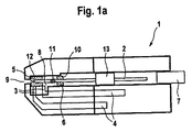
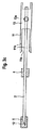
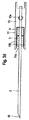
図1a〜cには、ディスポが3通りの異なる作動状態で示されている。図1aは、ランセット2を備えるディスポ1を未使用状態で示している。このときランセットの先端部12は防護キャップ5で取り囲まれている。このときランセット先端部12は、少なくとも1つの電極3とともにテスト室8の中にある。接点4が、電極3と測定器具との接続部を形成している。テスト室8は少なくとも2つの開口部9,10を有しており、開口部9は防護キャップ5で密閉されており、開口部10は同じく防護キャップ5で密閉されるか、または別のシール材6で密閉される。図1bには、使用時のディスポが示されている。保持部13は一方の側に切欠き13aを有しており、この切欠きは、駆動装置との結合を保証する役目を果たす(ここには図示せず)。このときランセット2は開口部9を通ってハウジングから外に出ている。図1cは、使用後にディスポ1の中にあるランセット2を示している。このときランセット2は、防護キャップ5だけでなくシール材6も一緒に引き込んでおり、開口部9と開口部10が両方とも空くようになっている。ランセットの近位端は、この状態のとき、接点7と接続されている。図1dには、複数の電極3を備えるディスポ1が示されている。本例では4つの電極があるが、この数はもっと多くてもよい。このことは、対照測定を実施するため、または試料液中の1つを超える分析物を測定するために利用される。本実施例ではテスト室の幾何学形状が改変されており、ランセット保持部13は、ランセットの作動後にテスト室の換気を保証する切欠き13aを追加的に有している。本実施形態では、保持部13は切欠き13aからテスト室まで換気通路を有している(ここには図示せず)。作動前には、テスト室の滅菌状態はこの切欠き13aの封止によって保証されており、作動時にはこの封止が取り外されるか、または傷つけられる(ここでは図示せず)。
In FIGS. 1a-c, the disposable is shown in three different operating states. FIG. 1 a shows the disposable 1 with the
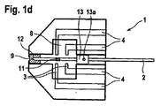
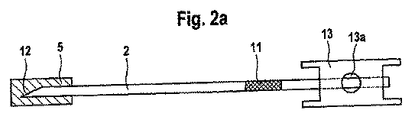
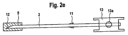
図2a〜fは、同じくランセット2をさまざまな作動状態で示している。ここでは捕捉装置11の原理が、さまざまな捕捉方法を図示しながら示されている。図2aには、捕捉装置11を備えるランセット2が休止状態で示されている。この捕捉装置は、ランセット2の近位端と遠位端の間にある。捕捉装置は、ランセット2が作動したときに防護キャップ5へ到達するように配置されている。防護キャップ5はハウジング開口部9よりも大きい直径を有しており、したがって防護キャップ5はもっとも遠くまで前方へ動くのを妨げられるからである。補足装置11は、ランセット2が最大に偏向したときに防護キャップ5に到達し、ランセット2が引き戻されると、捕捉装置11と防護キャップ5の協働作用に基づき、防護キャップ5も一緒に引き戻される。捕捉装置11は粗面化された面であるのが好ましく、図2a〜図2dに示すように、摩擦力に基づいて防護キャップ5が第2のシール材6と同じくこの面に付着する。図2cに示すような第2のシール材6は、ランセットが作動する前に、テスト室の第2の開口部10を閉止する役目をする。捕捉装置11の別の実施形態が図2eに示されている。ここでは捕捉装置11は捕捉剛毛によって具体化されている。捕捉装置11のさらに別の実施形態は、図3aに模式的に示されているような捕捉フックである。捕捉フックは保持部13によってランセットに固定されており、ランセット先端部12の方向に開口部11aを有している。開口部11aは、ランセット2が最大に偏向したときに防護キャップ5を把持し、ランセット2が引き戻されると同じく一緒にこれを運んでいく形態になっている。捕捉フックは少なくとも1つのアーム11bを有しており、その遠位端には、ランセット2の作動時に防護キャップ5の上を摺動し、それによって防護キャップ5を引っ掛ける逆鉤がある。図3bおよび図3dは、このような捕捉装置をランセット2の作動後に示している。これらの図面では、捕捉フックは2つの捕捉アーム11bを備えており、そのようにして防護キャップ5とシール材6を2つの側から包囲することができる。あるいは、捕捉フックは2つを超える捕捉アーム11bを有していてもよい。図3cおよび図3dには、少なくとも1つのアーム11bを備えるこのような捕捉フック原理が、追加のシール材6のケースについて示されている。このとき図3cはランセットを作動前の休止状態で示しており、図3dには、作動後のランセットが引き戻された防護キャップ5およびシール材6とともに示されている。
Figures 2a-f also show the
図3eおよび図3fは、作動後のランセット2の接触状態を示している。この状態のとき、ばね接点7はランセット保持部13の切欠き13aに係合する。このときばね接点7の屈曲した先端部15aが、ランセット2と接触する。液位管理部またはカウンター電極としてのランセット2の利用は、図4a〜図4cの対象となっている。ここではランセット2は作動後にばね接点7と接続される。
3e and 3f show the contact state of the
図4aに示す液位測定のために、ランセット2と電極3の間で変化する電位が計測される。テスト室8の充填は、直流電圧または交流電圧を印加したときの電流の測定によっても検知することができる。これに加えて、ランセット針を測定電極として利用することもでき、その様子は図4bに示されている。ここでもランセット2は引き戻された後に接点7と接触しており、直流電圧または交流電圧14が室内の作業電極3とランセット2の間で印加されている。テスト液とテスト薬品との反応による電極3での電流の変化を、このようにして測定することができる。このケースではテスト室内に1つの電極しか必要ない。図4cは、ランセット2の液位測定とカウンター電極という両方の追加特性の組み合わせを示している。ここでは2つの分離された電気回路14が、ランセット2と電極3に印加される。
For the liquid level measurement shown in FIG. 4a, the potential changing between the
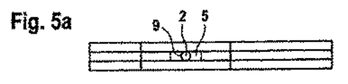
図5aはディスポ1の前面図を示しており、開口部9には防護キャップ5がランセット2とともに配置されている。テスト室を側面図として示す図5bには、テスト室8内でランセット2がどのように延びているかを見ることができる。
FIG. 5 a shows a front view of the disposable 1, and a
図5cは、電極を介して防護キャップ5にまで延びる楕円形のテスト室を示している。これに代わる室が図5dに示されており、ここでは楕円形の室が仕切によって電極と向かい合う側で仕切られており、それによって小さい室容積が具体化される。
FIG. 5 c shows an elliptical test chamber extending through the electrodes to the
図6は、防護キャップ5が第2の開口部10の閉止機構としても追加的に利用されるシステムを示しており、この開口部は本例ではカバーフィルムにある換気穴である。このシステムでは、室8内へ入り込む電極3と、室およびランセット先端部12を密閉してランセット3の別の部分を取り囲む防護キャップ5とを見ることができる。ランセット3の近位端にはランセット保持部13がある。ランセット保持部の手前には、捕捉装置11がランセット3の遠位端の方向に配置されている。
FIG. 6 shows a system in which the
Claims (12)
i)ランセットを含んでおり、該ランセットは、
ランセット針を含んでおり、該ランセット針は先端部と、
前記ランセット針を少なくとも前記先端部の領域で全面的に取り囲む防護キャップとを備えており、
前記ランセット針は前記防護キャップに対して相対的に変位可能であり、前記ランセットは、前記ランセットが引き戻されたときに前記防護キャップを一緒に引き戻すように前記防護キャップと協働作用し、
ii)試薬系を含む室を備えたテスト部材を含んでおり、前記室は前記防護キャップで閉止された開口部を有している分析補助手段。 In the analysis aid,
i) includes a lancet, the lancet
A lancet needle, the lancet needle having a tip,
A protective cap that entirely surrounds the lancet needle at least in the region of the tip,
The lancet needle is displaceable relative to the protective cap, the lancet cooperating with the protective cap to pull the protective cap back together when the lancet is pulled back;
ii) Analytical auxiliary means comprising a test member having a chamber containing a reagent system, the chamber having an opening closed by the protective cap.
ランセット針の先端部が防護キャップの中にあるランセットを準備するステップと、
前記ランセットが引き戻されるときに前記防護キャップを一緒に引き戻す捕捉装置を前記ランセットに準備するステップと、
試薬系と室の開口部とを含む、室を備えたテスト部材を準備するステップと、
前記ランセットを滅菌するステップと、
前記ランセットを前記室へ挿入し、前記防護キャップが前記室の前記開口部を閉止するようにするステップとを有している方法。 In a method for producing an analysis auxiliary means,
Preparing a lancet with the tip of the lancet needle in the protective cap;
Providing the lancet with a capture device that pulls the protective cap back together when the lancet is pulled back;
Providing a test member with a chamber comprising a reagent system and an opening of the chamber;
Sterilizing the lancet;
Inserting the lancet into the chamber such that the protective cap closes the opening of the chamber.
ランセットを含んでおり、該ランセットは、
ランセット針を含んでおり、該ランセット針は先端部と、
前記ランセット針を少なくとも前記先端部の領域で全面的に取り囲む防護キャップとを備えており、
前記ランセットが引き戻されるときに前記防護キャップを一緒に引き戻す、ランセットにある捕捉装置または表面構造と、
試薬変化が起きたときに生じる信号を検知する検出ユニットと、
前記信号に基づいて分析物の濃度を判定する評価装置とを含んでいる分析システム。 In an analysis system provided with an analysis auxiliary means,
A lancet, the lancet
A lancet needle, the lancet needle having a tip,
A protective cap that entirely surrounds the lancet needle at least in the region of the tip,
A capture device or surface structure on the lancet that pulls the protective cap back together when the lancet is pulled back;
A detection unit for detecting a signal generated when a reagent change occurs;
And an evaluation device for determining the concentration of the analyte based on the signal.
Applications Claiming Priority (2)
| Application Number | Priority Date | Filing Date | Title |
|---|---|---|---|
| EP05022830A EP1776925A1 (en) | 2005-10-20 | 2005-10-20 | Analyzing means with lancet and test element |
| PCT/EP2006/009944 WO2007045411A1 (en) | 2005-10-20 | 2006-10-14 | Analytical contrivance with sterile protection for the lancet and test chamber |
Publications (2)
| Publication Number | Publication Date |
|---|---|
| JP2009512467A true JP2009512467A (en) | 2009-03-26 |
| JP2009512467A5 JP2009512467A5 (en) | 2009-09-24 |
Family
ID=35892414
Family Applications (1)
| Application Number | Title | Priority Date | Filing Date |
|---|---|---|---|
| JP2008535945A Pending JP2009512467A (en) | 2005-10-20 | 2006-10-14 | Analytical support means with lancet and test room |
Country Status (8)
| Country | Link |
|---|---|
| US (1) | US20080243032A1 (en) |
| EP (2) | EP1776925A1 (en) |
| JP (1) | JP2009512467A (en) |
| CN (1) | CN101291621B (en) |
| AT (1) | ATE474502T1 (en) |
| DE (1) | DE502006007496D1 (en) |
| HK (1) | HK1125019A1 (en) |
| WO (1) | WO2007045411A1 (en) |
Cited By (3)
| Publication number | Priority date | Publication date | Assignee | Title |
|---|---|---|---|---|
| JP2022105703A (en) * | 2015-09-07 | 2022-07-14 | プラズマティカ リミテッド | Preventing fog on medical device viewport |
| US11974728B2 (en) | 2015-09-07 | 2024-05-07 | Plasmatica Ltd. | Preventing fog on a medical device viewport |
| US12070193B2 (en) | 2021-04-22 | 2024-08-27 | Plasmatica Ltd. | Multiple pumps for reducing pressure for plasma treatment |
Families Citing this family (13)
| Publication number | Priority date | Publication date | Assignee | Title |
|---|---|---|---|---|
| US8636672B2 (en) * | 2007-02-28 | 2014-01-28 | Nipro Diagnostics, Inc. | Test strip with integrated lancet |
| CN102415888A (en) * | 2006-01-05 | 2012-04-18 | 松下电器产业株式会社 | Blood test apparatus |
| KR20100031567A (en) * | 2007-04-29 | 2010-03-23 | 아크레이 가부시키가이샤 | Analyzing system |
| CN102325496B (en) | 2009-02-19 | 2015-10-07 | 霍夫曼-拉罗奇有限公司 | The joint space-efficient analyzing aid stores |
| EP2226008A1 (en) | 2009-02-19 | 2010-09-08 | Roche Diagnostics GmbH | Method for producing an analytical magazine |
| EP2226007A1 (en) | 2009-02-19 | 2010-09-08 | Roche Diagnostics GmbH | Test element magazine with covered test fields |
| EP2241252A1 (en) * | 2009-03-17 | 2010-10-20 | F. Hoffmann-La Roche AG | Testing device, in particular for blood sugar tests |
| US20130197452A1 (en) * | 2010-09-27 | 2013-08-01 | Terumo Kabushiki Kaisha | Medical instrument with attached needle |
| AU2012212655B2 (en) * | 2011-01-06 | 2015-12-24 | Pepex Biomedical, Inc. | Sensor module with enhanced capillary flow |
| US10631770B2 (en) | 2013-06-10 | 2020-04-28 | Facet Technologies, Llc | Lancet needle with alignment and retention notch |
| WO2016187780A1 (en) * | 2015-05-25 | 2016-12-01 | Coyote Bioscience Yixing Co., Ltd. | Device and method for sample collection |
| US10154809B2 (en) * | 2015-06-24 | 2018-12-18 | University Of Virginia Patent Foundation | Test strip device and related methods thereof |
| WO2024163311A1 (en) * | 2023-02-02 | 2024-08-08 | Siemens Healthcare Diagnostics Inc. | Laminate urinalysis assay strip and methods of producing and using same |
Citations (7)
| Publication number | Priority date | Publication date | Assignee | Title |
|---|---|---|---|---|
| US5125908A (en) * | 1990-10-19 | 1992-06-30 | Cohen Milton J | Hypodermic syringe with protective holder |
| JP2001133430A (en) * | 1999-11-08 | 2001-05-18 | Arkray Inc | Body-fluid measuring apparatus, and insertion body used by being inserted to the body-fluid-measuring apparatus |
| JP2003153885A (en) * | 2001-08-29 | 2003-05-27 | F Hoffmann La Roche Ag | Lancet and analytical apparatus having test element |
| JP2003527897A (en) * | 2000-03-04 | 2003-09-24 | エフ.ホフマン−ラ ロシュ アーゲー | Blood lancet with hygienic tip protection |
| JP2004512129A (en) * | 2000-10-31 | 2004-04-22 | エフ ホフマン−ラ ロッシュ アクチェン ゲゼルシャフト | Blood collection system |
| JP2004283568A (en) * | 2003-03-20 | 2004-10-14 | F Hoffmann-La Roche Ag | Incision aid with lancet system and prevention of reuse |
| JP4757301B2 (en) * | 2005-05-20 | 2011-08-24 | エフ ホフマン−ラ ロッシュ アクチェン ゲゼルシャフト | Lancet system with sterilization protection |
Family Cites Families (13)
| Publication number | Priority date | Publication date | Assignee | Title |
|---|---|---|---|---|
| DE3011211A1 (en) * | 1980-03-22 | 1981-10-01 | Clinicon Mannheim GmbH, 6800 Mannheim | BLOOD PLANT DEVICE FOR TAKING BLOOD FOR DIAGNOSTIC PURPOSES |
| US4627445A (en) * | 1985-04-08 | 1986-12-09 | Garid, Inc. | Glucose medical monitoring system |
| US4999582A (en) * | 1989-12-15 | 1991-03-12 | Boehringer Mannheim Corp. | Biosensor electrode excitation circuit |
| US5243516A (en) * | 1989-12-15 | 1993-09-07 | Boehringer Mannheim Corporation | Biosensing instrument and method |
| US4999632A (en) * | 1989-12-15 | 1991-03-12 | Boehringer Mannheim Corporation | Analog to digital conversion with noise reduction |
| US4963814A (en) * | 1989-12-15 | 1990-10-16 | Boehringer Mannheim Corporation | Regulated bifurcated power supply |
| US5352351A (en) * | 1993-06-08 | 1994-10-04 | Boehringer Mannheim Corporation | Biosensing meter with fail/safe procedures to prevent erroneous indications |
| WO1994029705A1 (en) * | 1993-06-08 | 1994-12-22 | Boehringer Mannheim Corporation | Biosensing meter which detects proper electrode engagement and distinguishes sample and check strips |
| US5366609A (en) * | 1993-06-08 | 1994-11-22 | Boehringer Mannheim Corporation | Biosensing meter with pluggable memory key |
| US5405511A (en) * | 1993-06-08 | 1995-04-11 | Boehringer Mannheim Corporation | Biosensing meter with ambient temperature estimation method and system |
| DE4320463A1 (en) * | 1993-06-21 | 1994-12-22 | Boehringer Mannheim Gmbh | Blood lancet device for drawing blood for diagnostic purposes |
| DE69809391T2 (en) * | 1997-02-06 | 2003-07-10 | Therasense, Inc. | SMALL VOLUME SENSOR FOR IN-VITRO DETERMINATION |
| DE19840856B4 (en) * | 1998-09-07 | 2008-04-10 | Roche Diagnostics Gmbh | System for obtaining a body fluid, lancet magazine, lancet, lancet set, lancing device and method for removing a lancet from a lancet magazine and use of the system |
-
2005
- 2005-10-20 EP EP05022830A patent/EP1776925A1/en not_active Withdrawn
-
2006
- 2006-10-14 WO PCT/EP2006/009944 patent/WO2007045411A1/en active Application Filing
- 2006-10-14 JP JP2008535945A patent/JP2009512467A/en active Pending
- 2006-10-14 DE DE502006007496T patent/DE502006007496D1/en active Active
- 2006-10-14 EP EP06806285A patent/EP1940289B1/en not_active Not-in-force
- 2006-10-14 AT AT06806285T patent/ATE474502T1/en active
- 2006-10-14 CN CN2006800392336A patent/CN101291621B/en not_active Expired - Fee Related
-
2008
- 2008-04-18 US US12/105,304 patent/US20080243032A1/en not_active Abandoned
-
2009
- 2009-04-09 HK HK09103371.4A patent/HK1125019A1/en not_active IP Right Cessation
Patent Citations (9)
| Publication number | Priority date | Publication date | Assignee | Title |
|---|---|---|---|---|
| US5125908A (en) * | 1990-10-19 | 1992-06-30 | Cohen Milton J | Hypodermic syringe with protective holder |
| JP2001133430A (en) * | 1999-11-08 | 2001-05-18 | Arkray Inc | Body-fluid measuring apparatus, and insertion body used by being inserted to the body-fluid-measuring apparatus |
| JP2003527897A (en) * | 2000-03-04 | 2003-09-24 | エフ.ホフマン−ラ ロシュ アーゲー | Blood lancet with hygienic tip protection |
| JP2005270679A (en) * | 2000-03-04 | 2005-10-06 | F Hoffmann La Roche Ag | Blood lancet with hygienic tip protection |
| JP2004512129A (en) * | 2000-10-31 | 2004-04-22 | エフ ホフマン−ラ ロッシュ アクチェン ゲゼルシャフト | Blood collection system |
| JP2003153885A (en) * | 2001-08-29 | 2003-05-27 | F Hoffmann La Roche Ag | Lancet and analytical apparatus having test element |
| JP2005185852A (en) * | 2001-08-29 | 2005-07-14 | F Hoffmann La Roche Ag | Method for manufacturing analytical device with lancet and test element |
| JP2004283568A (en) * | 2003-03-20 | 2004-10-14 | F Hoffmann-La Roche Ag | Incision aid with lancet system and prevention of reuse |
| JP4757301B2 (en) * | 2005-05-20 | 2011-08-24 | エフ ホフマン−ラ ロッシュ アクチェン ゲゼルシャフト | Lancet system with sterilization protection |
Cited By (4)
| Publication number | Priority date | Publication date | Assignee | Title |
|---|---|---|---|---|
| JP2022105703A (en) * | 2015-09-07 | 2022-07-14 | プラズマティカ リミテッド | Preventing fog on medical device viewport |
| JP7345923B2 (en) | 2015-09-07 | 2023-09-19 | プラズマティカ リミテッド | Preventing fogging of medical device viewports |
| US11974728B2 (en) | 2015-09-07 | 2024-05-07 | Plasmatica Ltd. | Preventing fog on a medical device viewport |
| US12070193B2 (en) | 2021-04-22 | 2024-08-27 | Plasmatica Ltd. | Multiple pumps for reducing pressure for plasma treatment |
Also Published As
| Publication number | Publication date |
|---|---|
| EP1776925A1 (en) | 2007-04-25 |
| DE502006007496D1 (en) | 2010-09-02 |
| WO2007045411A1 (en) | 2007-04-26 |
| CN101291621B (en) | 2010-09-01 |
| EP1940289A1 (en) | 2008-07-09 |
| CN101291621A (en) | 2008-10-22 |
| HK1125019A1 (en) | 2009-07-31 |
| ATE474502T1 (en) | 2010-08-15 |
| US20080243032A1 (en) | 2008-10-02 |
| EP1940289B1 (en) | 2010-07-21 |
Similar Documents
| Publication | Publication Date | Title |
|---|---|---|
| JP2009512467A (en) | Analytical support means with lancet and test room | |
| US8523784B2 (en) | Analytical device with lancet and test element | |
| JP4468324B2 (en) | Analysis aid | |
| JP6194307B2 (en) | Lancet operating method and apparatus | |
| EP1643908B1 (en) | System for withdrawing body fluid | |
| US8257276B2 (en) | Lancet device having capillary action | |
| US7819822B2 (en) | Body fluid sampling device | |
| JP2017140464A (en) | Integrated lancing device | |
| US8628724B2 (en) | Integrated needle and test strip with aspiration apparatus and method of use | |
| US20050283094A1 (en) | Disposable lancet and lancing cap combination for increased hygiene | |
| WO2010039447A1 (en) | Method and apparatus for a fluid sampling device | |
| JP2010519964A (en) | Test strip with integrated lancet | |
| JP2000232974A (en) | Specimen sampling implement and puncture device | |
| US8172866B2 (en) | Medical aid | |
| KR20190027240A (en) | Diagnostic strip with integrated lancet | |
| JP2003180663A (en) | Device for measuring body fluid component | |
| MXPA06010039A (en) | Body fluid sampling device |
Legal Events
| Date | Code | Title | Description |
|---|---|---|---|
| A521 | Request for written amendment filed |
Free format text: JAPANESE INTERMEDIATE CODE: A523 Effective date: 20090806 |
|
| A621 | Written request for application examination |
Free format text: JAPANESE INTERMEDIATE CODE: A621 Effective date: 20090806 |
|
| RD03 | Notification of appointment of power of attorney |
Free format text: JAPANESE INTERMEDIATE CODE: A7423 Effective date: 20100525 |
|
| A131 | Notification of reasons for refusal |
Free format text: JAPANESE INTERMEDIATE CODE: A131 Effective date: 20111206 |
|
| A02 | Decision of refusal |
Free format text: JAPANESE INTERMEDIATE CODE: A02 Effective date: 20120515 |