EP1776925A1 - Analyzing means with lancet and test element - Google Patents
Analyzing means with lancet and test element Download PDFInfo
- Publication number
- EP1776925A1 EP1776925A1 EP05022830A EP05022830A EP1776925A1 EP 1776925 A1 EP1776925 A1 EP 1776925A1 EP 05022830 A EP05022830 A EP 05022830A EP 05022830 A EP05022830 A EP 05022830A EP 1776925 A1 EP1776925 A1 EP 1776925A1
- Authority
- EP
- European Patent Office
- Prior art keywords
- lancet
- protective cap
- tip
- needle
- chamber
- Prior art date
- Legal status (The legal status is an assumption and is not a legal conclusion. Google has not performed a legal analysis and makes no representation as to the accuracy of the status listed.)
- Withdrawn
Links
Images


Classifications
-
- A—HUMAN NECESSITIES
- A61—MEDICAL OR VETERINARY SCIENCE; HYGIENE
- A61B—DIAGNOSIS; SURGERY; IDENTIFICATION
- A61B5/00—Measuring for diagnostic purposes; Identification of persons
- A61B5/145—Measuring characteristics of blood in vivo, e.g. gas concentration, pH value; Measuring characteristics of body fluids or tissues, e.g. interstitial fluid, cerebral tissue
- A61B5/1468—Measuring characteristics of blood in vivo, e.g. gas concentration, pH value; Measuring characteristics of body fluids or tissues, e.g. interstitial fluid, cerebral tissue using chemical or electrochemical methods, e.g. by polarographic means
- A61B5/1477—Measuring characteristics of blood in vivo, e.g. gas concentration, pH value; Measuring characteristics of body fluids or tissues, e.g. interstitial fluid, cerebral tissue using chemical or electrochemical methods, e.g. by polarographic means non-invasive
-
- A—HUMAN NECESSITIES
- A61—MEDICAL OR VETERINARY SCIENCE; HYGIENE
- A61B—DIAGNOSIS; SURGERY; IDENTIFICATION
- A61B5/00—Measuring for diagnostic purposes; Identification of persons
- A61B5/145—Measuring characteristics of blood in vivo, e.g. gas concentration, pH value; Measuring characteristics of body fluids or tissues, e.g. interstitial fluid, cerebral tissue
- A61B5/14532—Measuring characteristics of blood in vivo, e.g. gas concentration, pH value; Measuring characteristics of body fluids or tissues, e.g. interstitial fluid, cerebral tissue for measuring glucose, e.g. by tissue impedance measurement
-
- A—HUMAN NECESSITIES
- A61—MEDICAL OR VETERINARY SCIENCE; HYGIENE
- A61B—DIAGNOSIS; SURGERY; IDENTIFICATION
- A61B5/00—Measuring for diagnostic purposes; Identification of persons
- A61B5/15—Devices for taking samples of blood
- A61B5/150007—Details
- A61B5/150015—Source of blood
- A61B5/150022—Source of blood for capillary blood or interstitial fluid
-
- A—HUMAN NECESSITIES
- A61—MEDICAL OR VETERINARY SCIENCE; HYGIENE
- A61B—DIAGNOSIS; SURGERY; IDENTIFICATION
- A61B5/00—Measuring for diagnostic purposes; Identification of persons
- A61B5/15—Devices for taking samples of blood
- A61B5/150007—Details
- A61B5/150206—Construction or design features not otherwise provided for; manufacturing or production; packages; sterilisation of piercing element, piercing device or sampling device
- A61B5/150213—Venting means
-
- A—HUMAN NECESSITIES
- A61—MEDICAL OR VETERINARY SCIENCE; HYGIENE
- A61B—DIAGNOSIS; SURGERY; IDENTIFICATION
- A61B5/00—Measuring for diagnostic purposes; Identification of persons
- A61B5/15—Devices for taking samples of blood
- A61B5/150007—Details
- A61B5/150206—Construction or design features not otherwise provided for; manufacturing or production; packages; sterilisation of piercing element, piercing device or sampling device
- A61B5/150274—Manufacture or production processes or steps for blood sampling devices
- A61B5/150282—Manufacture or production processes or steps for blood sampling devices for piercing elements, e.g. blade, lancet, canula, needle
-
- A—HUMAN NECESSITIES
- A61—MEDICAL OR VETERINARY SCIENCE; HYGIENE
- A61B—DIAGNOSIS; SURGERY; IDENTIFICATION
- A61B5/00—Measuring for diagnostic purposes; Identification of persons
- A61B5/15—Devices for taking samples of blood
- A61B5/150007—Details
- A61B5/150358—Strips for collecting blood, e.g. absorbent
-
- A—HUMAN NECESSITIES
- A61—MEDICAL OR VETERINARY SCIENCE; HYGIENE
- A61B—DIAGNOSIS; SURGERY; IDENTIFICATION
- A61B5/00—Measuring for diagnostic purposes; Identification of persons
- A61B5/15—Devices for taking samples of blood
- A61B5/150007—Details
- A61B5/150374—Details of piercing elements or protective means for preventing accidental injuries by such piercing elements
- A61B5/150381—Design of piercing elements
- A61B5/150412—Pointed piercing elements, e.g. needles, lancets for piercing the skin
- A61B5/150435—Specific design of proximal end
-
- A—HUMAN NECESSITIES
- A61—MEDICAL OR VETERINARY SCIENCE; HYGIENE
- A61B—DIAGNOSIS; SURGERY; IDENTIFICATION
- A61B5/00—Measuring for diagnostic purposes; Identification of persons
- A61B5/15—Devices for taking samples of blood
- A61B5/150007—Details
- A61B5/150374—Details of piercing elements or protective means for preventing accidental injuries by such piercing elements
- A61B5/150381—Design of piercing elements
- A61B5/150503—Single-ended needles
- A61B5/150511—Details of construction of shaft
-
- A—HUMAN NECESSITIES
- A61—MEDICAL OR VETERINARY SCIENCE; HYGIENE
- A61B—DIAGNOSIS; SURGERY; IDENTIFICATION
- A61B5/00—Measuring for diagnostic purposes; Identification of persons
- A61B5/15—Devices for taking samples of blood
- A61B5/150007—Details
- A61B5/150374—Details of piercing elements or protective means for preventing accidental injuries by such piercing elements
- A61B5/150534—Design of protective means for piercing elements for preventing accidental needle sticks, e.g. shields, caps, protectors, axially extensible sleeves, pivotable protective sleeves
- A61B5/150572—Pierceable protectors, e.g. shields, caps, sleeves or films, e.g. for hygienic purposes
-
- A—HUMAN NECESSITIES
- A61—MEDICAL OR VETERINARY SCIENCE; HYGIENE
- A61B—DIAGNOSIS; SURGERY; IDENTIFICATION
- A61B5/00—Measuring for diagnostic purposes; Identification of persons
- A61B5/15—Devices for taking samples of blood
- A61B5/151—Devices specially adapted for taking samples of capillary blood, e.g. by lancets, needles or blades
- A61B5/15101—Details
- A61B5/15103—Piercing procedure
- A61B5/15107—Piercing being assisted by a triggering mechanism
- A61B5/15113—Manually triggered, i.e. the triggering requires a deliberate action by the user such as pressing a drive button
-
- A—HUMAN NECESSITIES
- A61—MEDICAL OR VETERINARY SCIENCE; HYGIENE
- A61B—DIAGNOSIS; SURGERY; IDENTIFICATION
- A61B5/00—Measuring for diagnostic purposes; Identification of persons
- A61B5/15—Devices for taking samples of blood
- A61B5/151—Devices specially adapted for taking samples of capillary blood, e.g. by lancets, needles or blades
- A61B5/15186—Devices loaded with a single lancet, i.e. a single lancet with or without a casing is loaded into a reusable drive device and then discarded after use; drive devices reloadable for multiple use
- A61B5/15188—Constructional features of reusable driving devices
- A61B5/1519—Constructional features of reusable driving devices comprising driving means, e.g. a spring, for propelling the piercing unit
-
- A—HUMAN NECESSITIES
- A61—MEDICAL OR VETERINARY SCIENCE; HYGIENE
- A61B—DIAGNOSIS; SURGERY; IDENTIFICATION
- A61B5/00—Measuring for diagnostic purposes; Identification of persons
- A61B5/15—Devices for taking samples of blood
- A61B5/151—Devices specially adapted for taking samples of capillary blood, e.g. by lancets, needles or blades
- A61B5/15186—Devices loaded with a single lancet, i.e. a single lancet with or without a casing is loaded into a reusable drive device and then discarded after use; drive devices reloadable for multiple use
- A61B5/15188—Constructional features of reusable driving devices
- A61B5/15192—Constructional features of reusable driving devices comprising driving means, e.g. a spring, for retracting the lancet unit into the driving device housing
- A61B5/15194—Constructional features of reusable driving devices comprising driving means, e.g. a spring, for retracting the lancet unit into the driving device housing fully automatically retracted, i.e. the retraction does not require a deliberate action by the user, e.g. by terminating the contact with the patient's skin
-
- A—HUMAN NECESSITIES
- A61—MEDICAL OR VETERINARY SCIENCE; HYGIENE
- A61B—DIAGNOSIS; SURGERY; IDENTIFICATION
- A61B5/00—Measuring for diagnostic purposes; Identification of persons
- A61B5/15—Devices for taking samples of blood
- A61B5/157—Devices characterised by integrated means for measuring characteristics of blood
-
- A—HUMAN NECESSITIES
- A61—MEDICAL OR VETERINARY SCIENCE; HYGIENE
- A61B—DIAGNOSIS; SURGERY; IDENTIFICATION
- A61B2562/00—Details of sensors; Constructional details of sensor housings or probes; Accessories for sensors
- A61B2562/02—Details of sensors specially adapted for in-vivo measurements
- A61B2562/0295—Strip shaped analyte sensors for apparatus classified in A61B5/145 or A61B5/157
-
- A—HUMAN NECESSITIES
- A61—MEDICAL OR VETERINARY SCIENCE; HYGIENE
- A61B—DIAGNOSIS; SURGERY; IDENTIFICATION
- A61B5/00—Measuring for diagnostic purposes; Identification of persons
- A61B5/145—Measuring characteristics of blood in vivo, e.g. gas concentration, pH value; Measuring characteristics of body fluids or tissues, e.g. interstitial fluid, cerebral tissue
- A61B5/1486—Measuring characteristics of blood in vivo, e.g. gas concentration, pH value; Measuring characteristics of body fluids or tissues, e.g. interstitial fluid, cerebral tissue using enzyme electrodes, e.g. with immobilised oxidase
- A61B5/14865—Measuring characteristics of blood in vivo, e.g. gas concentration, pH value; Measuring characteristics of body fluids or tissues, e.g. interstitial fluid, cerebral tissue using enzyme electrodes, e.g. with immobilised oxidase invasive, e.g. introduced into the body by a catheter or needle or using implanted sensors
Definitions
- the invention relates to an analytical device which contains a sterile-protected lancet and an analytical test chamber. Furthermore, the invention relates to a method for producing such an analytical aid.
- this method is suitable if the analysis of the blood sample can be carried out immediately after obtaining the blood.
- lancets and matching devices are used that allow a low-pain and reproducible blood collection.
- lancets with lancing devices to lower the psychological threshold for the stinging of one's own body, which is especially for children who are suffering from diabetes and rely on regular blood glucose tests, is of particular importance.
- lancets and lancing devices examples include the devices commercially available (lancing devices) and lancets Glucolet ® Bayer AG and Softclix ® from Roche Diagnostics GmbH may be mentioned. Such lancets and devices (lancing devices) are z. B. Subject of WO-A 98/48695 . EP-A 0 565 970 . US 4,442,836 or US 5,554,166 ,
- B. AccuChek Sensor (from Roche Diagnostics) consists of a meter into which a test element (test strip, sensor) is inserted. The test strip is brought into contact with a drop of blood previously obtained by means of a finger-stick or other part of the body.
- the numerous system components (lancet, lancing device, test strips and measuring device) require a lot of space and cause a relatively complex handling. Meanwhile, there are also systems with a higher degree of integration and thus a simpler handling.
- test strips are stored in the measuring device and made available for the measurement.
- a next step in miniaturization can be achieved, for example, by integrating multiple functions or functional elements in a single analytical tool (disposable).
- a suitable combination of lancing process and sensory analyte concentration detection on a test strip for example, the operating procedure can be significantly simplified.
- EP-B 0 199 484 (Audio Bionics) describes an analytical tool ("Disposable”, short: Dispo) with integrated lancet, which is actuated on the device side (see, for example, Figure 9). By means of a specific spring bearing (spring-mounted lance means), the lancet is pulled back after the puncture.
- the dispenser contains a so-called wick means by which the sample liquid is conducted from the body surface to the analysis area, an optically evaluable test field.
- US 6,143,164 (E. Heller & Comp.) Describes a method in which a body opening (for example a small puncture or cut through the skin) is produced and subsequently body fluid is transported into a sensor and examined there for the presence of an analyte.
- US 6,143,164 discloses an analytical aid, in which a lancet device mounted on a sensor test strip. The transport of the sample liquid from the body opening to the actual detection element of the sensor takes place, for example, again via a "wick means" or else via capillary gaps / channels.
- US 2003153939 describes a protective mechanism for a lancet or its lancet tip, which keeps the tip sterile until the lancing process and subsequently ensures hygienic storage.
- the protective mechanism is pierced during the lancing process and the lancet after the lancing process again surrounded by the protective body, so that no pollution of the environment is given by the lancet used.
- US 2003050573 relates to a lancet protection in an integrated system that keeps the lancet tip sterile until lancing. In doing so, the sterile lancet tip emerges from an exit opening that is locally separate from the opening into which the blood sample is taken.
- the object of the present invention was therefore to eliminate the disadvantages of the prior art.
- the guarantee of lancet sterility for the period of the exhaustion period should be granted by the inventive dispo with simultaneous integration of lancet and test element.
- the shortest possible path for the liquid to be analyzed should be ensured from the dispo-opening to the test element.
- this system should have a high level of operating comfort, in which the patient does not have to worry about the blood collection after the sting.
- the object of the present invention to provide analytical aids with lancets, in which at least the lancet needle tip in the unused state until immediately prior to use sterile, that is kept germ-free, and can be stored hygienically in the used state.
- this task should be solved without the user having to take separate measures for hygienic storage.
- the user should be protected against unintentional injury to the lancet, especially the lancet used.
- a simple sample transfer from the site of blood collection to the site of the blood test should be possible.
- a first subject of the invention is an analytical aid containing a lancet.
- the lancet has as preferred components a lancet needle with a tip and a protective cap which completely surrounds the lancet needle at least in the region of the tip.
- the lancet needle is displaceable relative to the protective cap.
- the protective cap may consist of different materials which are pierceable and in which the tip of the lancet needle is embedded.
- the analytical aid further contains an analytical test element consisting from a chamber containing a detection element with a reagent system. This chamber has an opening through which the lancet is moved during the lancing process. This opening is closed by the protective cap of the lancet needle.
- the solution according to the invention preferably consists of a miniaturized Dispo, in which the three functions stinging, blood transfer from the wound produced by the stinging to the test element, and detection of the analyte, are combined in one body.
- the main body of the analytical aid according to the invention consists of a rigid plastic body, preferably with cavities, the outer shape of which is preferably adapted accordingly for the purpose of closing a housing opening.
- a lancet needle is embedded such that its tip preferably does not protrude beyond the front edge of the body.
- the main body can therefore also be referred to as a protective cap.
- the basic body has in a preferred embodiment webs which serve to fix the needle in the body and to guide during the piercing movement.
- the majority of the needle is not connected to the main body in order to minimize the frictional forces during the lancing movement.
- the contact surfaces between the needle and the protective cap are preferably minimized and suitably pretreated, for example siliconized.
- the analytical aid consists of a housing in which the lancet needle with protective cap and the test element are located.
- at least one electrode is present in the test chamber during electrochemical measurement.
- the housing consists of two housing parts. These housing parts can be made by injection molding of different plastics. A non-limiting range of polymers are polyesters, polycarbonate, polyvinylchloride, polymethylmethacrylate, co-polyesters and mixtures thereof. In optical evaluation of the test element is a part of the housing made of transparent material.
- the lancets according to the invention are preferably designed for single use and can therefore also be referred to as disposable blood lancets or disposable blood lancets.
- the lancet of the invention includes a needle (lancet needle) with a tip.
- the needle is usually several millimeters (mm) to a few centimeters (cm) long and has an elongated shape on.
- needles typically have a cylindrical shape, since this needle shape is particularly easy to produce; However, there are also needle shapes with different shapes possible.
- the tip region of the needle includes the needle tip, which is inserted into tissue during proper use of the lancet. The tip of the lancet needle is thus the part of the lancet that comes into contact with the skin of the individual to be stung, possibly injuring the latter and thus causing the outflow of a body fluid, in particular blood or interstitial fluid.
- the tip of the lancet needle for example, be rotationally symmetric, as is generally the case with pins.
- the resulting, inclined to the longitudinal axis of the needle, tapering in a peak edges are used during piercing as a sharp edge and make the puncture pain less than is the case with unpolished needles.
- the lancet needle of the lancet according to the invention is made of a material which is sufficiently hard to withstand mechanical stress during the piercing process, the processing steps or possibly other stresses occurring without deformation. Furthermore, the material must be such that particles do not break off or peel off during the puncturing process. Finally, the needle material must also be machinable so that the needle tip sufficiently sharp and the edges of the needle tip can be ground sufficiently sharp, if necessary. Highly suitable materials for the lancet needle are mainly metals and of these, in particular stainless steels. If the property of the lancet as a level meter and counter electrode is dispensed with, however, also needles made of silicon, ceramic or plastics are conceivable. Stainless steel needles are particularly preferred.
- the tip of the lancet needle of the lancet according to the invention is surrounded by the protective cap.
- the protective cap in the region of the tip of the lancet needle consists of a material which can be pierced for the lancet tip. If the protective cap is made of an elastic material, it preferably completely surrounds the lancet tip. Thus, the lancet tip is sealed from the environment.
- the elastic material of the Schutzkappes which can form the protective cap completely or only partially in various embodiments, characterized in that it is soft, deformable and pierceable by the lancet needle with its tip, without damaging the tip.
- the lancet tip is surrounded by the protective cap such that there is a cavity between the lancet tip and the protective cap wall.
- the wall thickness of the protective cap material is designed so that here, too, no deformation and wear of the ground edges of the lancet tip occurs when piercing.
- the lancet needle is moved along its longitudinal axis relative to the protective cap and emerges with its tip through the protective cap from the housing so as to be able to pierce the skin of the individual to be examined in order to obtain blood.
- the elastic material of the protective cap which completely encloses the tip of the lancet needle, ensures the sterility of the lancet needle tip prior to its use, preferably until just prior to use.
- the elastic material is thus germ-proof for the penetration or escape of germs in the unused state of the lancet needle.
- the elastic material provides mechanical protection for the lancet needle tip and thus also prevents unintentional injury to the lancet needle tip.
- rubber, rubber, silicone, elastomers and especially thermoplastic elastomers have been found to be suitable. These have the characteristics essential to the present invention: they are soft, deformable, pierced by the lancet needle without injuring the tip, and close tightly around the unused lancet needle point. In addition, they can be used for injection molding processes that enable mass production of large numbers of lancets.
- Thermoplastic elastomers which are also called elastoplasts or thermoplastics or thermoplastic rubbers, ideally have a combination of the performance properties of elastomers and the processing properties of thermoplastics.
- Thermoplastic elastomers are, for example, styrene-oligoblock copolymers (so-called TPE-S), thermoplastic polyolefins (TPE-O), thermoplastic polyurethanes (TPE-U), thermoplastic copolyesters (TPE-E) and thermoplastic copolyamides (TPE-A).
- thermoplastic elastomers based on styrene-ethylene-butylene-styrene polymer (SEBS polymers, e.g., B. Evoprene ® from Evode Plastics or Thermolast K from Kunststoffwerk Kraiburg GmbH) have been found suitable.
- the lancet needle is moved relative to the protective cap.
- the protective cap is preferably fixed in position by the lancing device or the puncturing device.
- the lancet needle may be specially shaped for the purpose of its drive, for example, it may have a needle head at the tip opposite end, or in addition to the protective cap which surrounds the tip, have a further lancet body or lancet position, which are gripped by a drive element of the lancing device can.
- the shape of the needle or the additional lancet position can interact in a suitable manner with a corresponding drive device in the lancing device (lancing aid).
- such means may be referred to as a driving device of the needle.
- Such drive devices are well known to the person skilled in the art, for example from the patent applications US 6,783,537B1 or EP 1 336 375 ,
- the elastic material may be connected this with a rigid material, such as a rigid plastic material.
- the elastic material may be stabilized, for example, on its outside, which does not come into contact with the tip of the lancet needle, with a layer of a stiff material, for example a rigid plastic.
- a layer of a stiff material for example a rigid plastic.
- manufacture the lancet protection only in the region of the lancet needle tip from an elastic material, but otherwise to manufacture the sheath of the lancet from conventional, rigid plastics.
- the elastic material and the rigid material may be glued together or be connected to each other by an injection molding process, for example a two-component injection molding process.
- the rigid material of the lancet sheath ensures a mechanical stabilization of the elastic material during the lancing process and facilitates the fixation of the elastic part of the protective cap during the lancing process by the lancing device.
- the rigid material may also be part of the test element, for example a capillary gap test element as shown in FIG WO 99/29429 is described.
- the entire protective cap may consist of a rigid plastic material.
- the patient comes during the lancing process with the cap or only partially in contact. Rather, the patient puts his finger on the opening of the housing, which is preferably not on the side of the drive and the coupling of the Dispos to the meter. After applying the finger, the patient can trigger a mechanism that causes the lancet to move from rest to an actuated state and back to rest.
- the lancet moves with its distal end, so the tip, for a short period of time through the opening out of the housing.
- a catching device which is coupled to the lancet body or with him, the protective cap, which also remains during the engraving in the housing.
- the transfer of blood from the wound / puncture site of the lancet to the measuring site is realized according to the invention in the following way:
- the blood transfer is accomplished without any intervention by the user of the device according to the invention, so to speak "automatically".
- the Dispo may have means for sample liquid transport.
- these agents are capillary active, for example, formed as a column or channels in a rigid body or as absorbent matrix materials. It is also possible a combination of these two principal possibilities, for example, that the blood is first passed through a capillary channel, taken over by an absorbent matrix material and discharged into a test chamber.
- Absorbent nonwovens, papers, wicks or fabrics have proven to be suitable as absorbent matrix materials for the purposes of this invention.
- the base body, preferably the test chamber, of the analytical aid contains the means for transporting sample liquid.
- This may be an absorbent wick embedded in the chamber or, preferably, a shaped capillary gap which also serves as an outlet for the lancet. This ensures that the collection for blood intake does not have to be postponed.
- the geometry of the inlet opening is designed such that the blood drop formed can be collected and entered as easily as possible, for example as a funnel or notch.
- the capillary action then ensures the suction of the required amount of blood, which can be well below 1 microliter.
- the blood passes in this way into the chamber to the test field and reacts there with the test chemistry, whereby an evaluable electrical signal or a color change is generated.
- the capillary gap can be molded during injection molding in the plastic or subsequently introduced into the Kunststofflcörper, for example, embossed or milled.
- the aspiration of the sample drop into the capillary channel is achieved by hydrophilizing the surface exposed by the recess and bordering directly on a capillary-active zone, at least in the direction of the capillary transport channel.
- Hydrophilic surfaces are water-attracting surfaces in this context. Aqueous samples, including blood, spread well on such surfaces. Such areas are among other things characterizes that at the interface a drop of water on them forms a sharp edge or contact angle. In contrast, on hydrophobic, that is, water-repellent surfaces, formed at the interface between water droplets and surface an obtuse edge angle. The readiness of a capillary to absorb a liquid is associated with the wettability of the channel surface with the liquid. For aqueous samples, this means that a capillary should be made of a material whose surface tension is close to, or greater than, that of water (72 mN / m).
- Hydrophobic plastic capillaries such as polystyrene (PS), polypropylene (PP) or polyethylene (PE), do not substantially wick aqueous samples. This implies the need to render plastics hydrophilic for use as construction material for test elements with capillary-active channels, ie to hydrophilize them.
- PS polystyrene
- PP polypropylene
- PE polyethylene
- the hydrophilization of the surface of the capillary channel is achieved in that a hydrophilic material is used for its production, which, however, is not able to absorb the sample liquid itself or at least substantially.
- the hydrophilization of a hydrophobic or only slightly hydrophilic surface can be achieved by suitable coating with a stable hydrophilic layer inert to the sample material, for example by covalent bonding of photoreactively-treated, hydrophilic polymers to a plastic surface by application wetting agent-containing layers or by coating surfaces with nanocomposites by means of sol-gel technology.
- the hydrophilization is achieved by the use of thin layers of oxidized aluminum. These layers are either applied directly to the desired components of the test element, for example by vacuum evaporation of the workpieces with metallic aluminum and subsequent oxidation of the metal, or in the form of metal foils or metal-coated plastic films for the test carrier structure, which also oxidizes to achieve the desired hydrophilicity Need to become. Metal layer thicknesses of 1 to 500 nm are sufficient. The metal layer is then oxidized to form the oxidized form, wherein, in addition to the electrochemical, anodic oxidation especially the oxidation in the presence of steam or by boiling in water have been found to be particularly suitable methods. Depending on the method, the oxide layers obtained in this way are between 0.1 and 500 nm, preferably between 10 and 100 nm thick. Although larger layer thicknesses of both the metal layer and the oxide layer are in principle practically feasible, but show no further advantageous effects.
- the detection element of the analytical test element according to the invention contains all the reagents necessary for the detection reaction of the target analyte in the sample and optionally excipients.
- the detection element can also contain only parts of the reagents or auxiliaries. Those skilled in the art of analytical test elements or diagnostic test carriers are well aware of such reagents and auxiliaries.
- enzymes, enzyme substrates, indicators, buffer salts, inert fillers and the like may be more contained in the detection element.
- the detection element may be composed of one or more layers and optionally contain an inert support, preferably on the side of the detection element that is not brought into contact with the sample.
- the detection reaction leads to an observable color change, which in this context is to be understood as either the change of a color, the appearance of a color or the disappearance of color, it is to be ensured that the support by appropriate measures a visual or optical observation of the detection reaction allows.
- the support material of the detection element itself may be transparent, for example a transparent plastic film, such as polycarbonate film, or have a transparent recess on the detection side.
- detection reactions that lead to color changes those skilled in the art also other detection principles are known, which can be implemented with the test element described, for example, electrochemical sensors.
- At least one electrode is in the test chamber.
- the electrode is connected to the meter via a contact on the dispo.
- the lancet can be used as a second electrode.
- the lancet is preferably connected via a spring contact with the meter, but also rigid contacts of the lancet with the meter are possible.
- the measurement can be carried out with both direct current and alternating current.
- the test chamber contains both the lancet tip with protective cap and the necessary detection chemicals and, with electrochemical detection, the electrodes.
- the size of the test chamber is such that a minimal volume of the test fluid is needed. This is ideally below one ⁇ l.
- hydrophilic materials are used to produce the test chamber.
- the test chamber can have different geometries.
- the chamber can be cubic or cuboid.
- the chamber can also take the form of a round or oval Habkugel.
- the chamber has at least one opening through which the lancet exits upon actuation. At rest, prior to use, this opening is closed by the protective cap surrounding the lancet tip. After actuation of the lancet further ventilation of the chamber is needed to achieve capillary action in the chamber. This can be ensured by a second opening of the chamber or by a ventilation hole in the lancet holder, which is closed by a foil or other Verresslung before use of the lancet.
- the geometry and volume of the chamber are dependent on the number of electrodes in the chamber. The number of electrodes depends on the type of use of the auxiliary.
- At least one electrode is in the test chamber and the lancet can be used as a counter or reference electrode. This can be supplemented by additional electrodes. By adding more electrodes, it is possible to determine more than one analyte independently. These analytes may be, for example, blood components such as cholesterol, triglycerides, coagulation factors and other blood parameters.
- the volume of the chamber is between 100 nl and 1000 nl, but may also be greater when using a plurality of electrodes. In a preferred embodiment, the volume is between 300 nl and 600 nl, more preferably at 500 nl.
- the electrodes and their contacts are made of a conductive material, such as conductive plastics or metal.
- both the electrodes and their contacts and the lancet made of conductive material, such.
- conductive material such as aluminum, lead, iron, gallium, gold, indium, iridium, carbon (such as graphite), cobalt, copper, magnesium, nickel, niobium, osmium, palladium, platinum, mercury (as amalgam), rhenium, rhodium, selenium, Silicon (such as highly doped polycrystalline silicon), silver, tantalum, titanium, uranium, vanadium, tungsten, tin, zinc, zirconium, mixtures and alloys thereof, oxides or metal mixtures of the listed elements.
- the contacts and electrodes include gold, platinum, palladium, iridium or mixtures or alloys of these metals.
- the contacts may be made of a different material than the electrodes.
- the lancet tip may have a different composition than the rest of the lancet body.
- a preferred embodiment is a silver / silver halide electrode as a reference electrode and a (eg, screen printed) graphite electrode as a working electrode.
- the housing of the device has at least one optically transparent housing wall, which is mounted either below or above the test chemistry.
- the housing of the device has at least one optically transparent housing wall, which is mounted either below or above the test chemistry.
- a combination of electrochemical and optical measurement is also possible.
- a light beam is directed onto the test field, the interaction of which with the liquid can be measured either in reflection or transmission.
- an optically transparent housing wall is used both on the side of the irradiation and on the detection side.
- a detection element which is part of the test element and contains the detection reagents, is fixed on the transparent surface of the test chamber.
- an optical feature changes, which is detected by means of an optical module.
- This optical module may be a photosensor or a photomultiplier, or else an optical sensor unit known from the prior art.
- the radiation source may also be one known in the art.
- the retracted lancet can also be used as a level gauge.
- the catching device which serves to retract the protective cap and / or another seal, may have various embodiments.
- An embodiment of the invention is the roughening of the lancet surface at a suitable location of the lancet body. This arises during the Contact this roughened surface with the sealing bodies or a sufficient frictional effect, so that when retracting the lancet or the seal body adhere to it.
- a second embodiment of the invention is a fishing hook, which in turn may have various embodiments.
- the principle is the hooking of the seal body to the barbs of the lancet body at the maximum outlet of the lancet.
- the catch hook may consist of bristle-shaped formations or hooks from the lancet, which have their orientation to the proximal end of the lancet.
- These hooks may be made of various preferably non-deformable materials such as metal, ceramic or polymers, preferably of metal.
- a catch hook that slides over the seal body and encloses it. By enclosing the seal body retraction of the seals is effected when the lancet is withdrawn after Aktuation again.
- This fishing hook is connected to the lancet body via a holder.
- the catch hook has at least one arm which extends in the direction of the lancet tip and is equipped with a hook at the distal end. The hook inverts at maximum deflection of the lancet over the or the seal body.
- a preferred embodiment is selected with at least two arms.
- This catch hook or the roughened surface on the lancet pulls back both the protective cap, as well as other existing seals in the housing.
- the retracted seals open both the exit opening and another opening for venting the test chamber.
- This seal of the test chamber prevents the electrodes and the test reagents from becoming contaminated during storage.
- the protective cap also prevents unwanted, premature contact of the patient with the lancet.
- Measuring devices which are known to those skilled in the art, which have various features such as algorithms for evaluation as well as different energy sources for the supply of the Dispos are in the following applications US 4,963,814; US 4,999,632 ; US 4,999,582 ; US 5,243,516 ; US 5,352,351 ; US 5,366,609 ; US 5,405,511 ; US 5,438,271 ,
- the lancet and housing can be connected to one another before or after sterilization of the lancet. Sterilization after assembly has the consequence that the test chemistry is adequately covered during sterilization, as otherwise damage to the reagents may occur.
- the invention relates to the use of a plastic material as part of a lancet of an analytical aid, wherein the plastic material serves to maintain the sterility of at least the tip of a lancet needle in the unused state.
- the sterility of the lancet needle tip in the unused state must be established by appropriate measures, such as treatment with ionizing radiation. Once sterilized, the lancet needle tips remain preserved by the corresponding protective caps, which include, inter alia, an elastic material.
- the use of the protective cap according to the invention additionally enables the sealing of at least one opening of the test chamber. This at least one opening is at the same time the outlet opening for the lancet and the inlet opening for the body fluid.
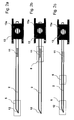
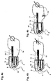
- FIG. 1 a-c the disposition is shown in three different action states.
- Figure 1 a shows the Dispo (1) with the lancet (2) in unused condition.
- the tip (12) of the lancet is surrounded by a protective cap (5).
- the lancet tip (12) is located here with at least one electrode (3) in a test chamber (8).
- Contacts (4) form a connection of the electrodes (3) with a measuring device.
- the test chamber (8) has at least two openings (9, 10) wherein the opening (9) is sealed by the protective cap (5) and the opening (10) is either also sealed by the protective cap (5) or by another seal ( 6).
- Figure 1 b the Dispo is shown in use.
- the holder (13) has on one side a recess (13a) which serves to ensure a connection to a drive (not shown here).
- the lancet (2) emerges from the housing through the opening (9).
- FIG. 1 c shows the lancet (2) after its use in the dispenser (1).
- the lancet (2) has withdrawn both the protective cap (5) and the seal (6) so far that both the opening (9) and the opening (10) are released.
- the proximal end of the lancet in this state communicates with a contact (7).
- FIG. 1 d shows a disposition (1) with a plurality of electrodes (3). In this case, there are 4 electrodes, but this can be more. This is to perform control measurements or measure more than one analyte in the sample fluid.
- the geometry of the test chamber is changed, so that lancet holder (13) additionally has a recess (13a), which ensures ventilation of the test chamber after actuation of the lancet.
- the holder (13) has a ventilation channel from the recess (13a) to the test chamber (not shown here). Prior to actuation, the sterility of the test chamber is ensured by a seal of this recess (13a), which is eliminated or injured upon actuation (not shown here).
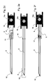
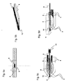
- FIG. 2a the lancet (2) is shown with a catching device (11) at rest.
- the catcher is located between the proximal and distal ends of the lancet (2). It is arranged so that it reaches the protective cap (5) upon actuation of the lancet (2), since the protective cap (5) has a larger diameter than the housing opening (9) and thus the Protective cap (5) is prevented from moving forward further.
- the catcher (11) reaches at maximum deflection of the lancet (2), the protective cap (5) and when retracting the lancet (2), the protective cap (5) due to the interaction of catcher (11) and protective cap (5) with retracted.
- the catching device (11) is preferably a roughened surface on which due to frictional forces the protective cap (5) as well as a second seal (6) hang, as shown in Figures 2 a to 2 d.
- the second seal (6) serves to close a second opening (10) of the test chamber before the lancet is actuated.
- Another embodiment of the catcher (11) is shown in Figure 2 e.
- the catcher (11) is realized by Fangborsten.
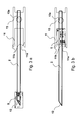
- a further embodiment of the catching device (11) is a catch hook as shown schematically in FIG. 3a.
- the catch hook is fixed by means of a holder (13) on the lancet and has an opening (11a) in the direction of the lancet tip (12).
- the opening (11a) is of the shape that it engages the protective cap (5) at maximum deflection of the lancet (2) and also with the retraction of the lancet (2) also transported back.
- the catch hook has at least one arm (11b) at the distal end of a barb, which pushes upon actuation of the lancet (2) on the protective cap (5) and thus captures the protective cap (5).
- FIGS. 3b and 3d show this catching device after actuation of the lancet (2).
- the catch hook is equipped with two catch arms (11b) and can thus enclose the protective cap (5) and the seal (6) from two sides.
- the catch hook can also have more than 2 tentacles (11b).
- Figures 3c and 3d of this fishing hook principle with at least one arm (11b) for the case of an additional seal (6) is shown.
- FIG. 3c shows the lancet at rest before the actuation
- FIG. 3d shows the lancet after the actuation with the protective cap (5) and seal (6) withdrawn.
- FIGS. 3e and 3f show the contacting of the lancet (2) after the actuation.
- a spring contact (7) engages in a recess (13a) of the lancet holder (13).
- the bent tip (15 a) of the spring contact (7) with the lancet (2) comes into contact.
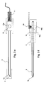
- the use of the lancet (2) as fill level control or counter electrode is the subject of FIGS. 4a to 4c. In this case, the lancet (2) after Aktuation with a spring contact (7) in connection.
- FIG. 4 a For level measurement, shown in FIG. 4 a, the changing potential between lancet (2) and electrode (3) is measured.
- the filling of the test chamber (8) can also be detected by measuring a current when applying a DC or AC voltage.
- the Lancet needle can be used as a measuring electrode, which is shown in Figure 4 b.
- the lancet (2) after withdrawal with a contact (7) in connection and it is a DC or AC voltage (14) between the working electrode (3) in the chamber and the lancet (2) applied.
- the change of the current flow through the reaction of the test liquid with the test chemistry on the electrode (3) can be measured in this way. In this case, only one electrode is needed in the test chamber.
- FIG. 4 c shows a combination of the two additional properties of level measurement and counterelectrode of the lancet (2).
- two separate circuits (14) are applied to lancet (2) and electrode (3).
- FIG. 5a shows a front view of the device (1), wherein the protective cap (5) with the lancet (2) is arranged in the opening (9).
- Figure 5b which shows the test chamber in a side view, the course of the lancet (2) in the test chamber (8) can be seen.
- Fig. 5c shows an oval test chamber which extends over the electrodes to the protective cap (5).
- An alternative chamber is shown in Figure 5d, wherein the oval chamber is delimited by a boundary on the opposite side of the electrodes and thereby a smaller chamber volume is realized.
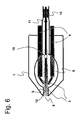
- FIG. 6 shows a system in which the protective cap (5) additionally serves as a closing mechanism for the second opening (10), which in this case is a venting hole in the lidding film.
- the electrodes (3) which extend into the chamber (8) and the protective cap (5), which seals the chamber and the lancet tip (12) and encloses another part of the lancet (3).
- the lancet holder 13
- the catching device (11) is arranged in the direction of the distal end of the lancet (3).
Abstract
Description
Die Erfindung betrifft ein analytisches Hilfsmittel, welches eine steril geschützte Lanzette und eine analytische Testkammer enthält. Weiterhin betrifft die Erfindung ein Verfahren zur Herstellung eines solchen analytischen Hilfsmittels.The invention relates to an analytical device which contains a sterile-protected lancet and an analytical test chamber. Furthermore, the invention relates to a method for producing such an analytical aid.
Die Untersuchung von Blutproben ermöglicht in der klinischen Diagnostik das frühzeitige und zuverlässige Erkennen von pathologischen Zuständen sowie die gezielte und fundierte Kontrolle von Körperzuständen. Die medizinische Blutdiagnostik setzt stets die Gewinnung einer Blutprobe des zu untersuchenden Individuums voraus. Während in Kliniken und bei niedergelassenen Ärzten oftmals durch eine Venenpunktion mehrere Milliliter Blut einer zu untersuchenden Person für die Analyse gewonnen werden, um damit eine Vielzahl von Labortests durchführen zu lassen, reichen für einzelne Analysen, die gezielt auf einen Parameter gerichtet sind, heutzutage oftmals wenige Mikroliter bis hin zu weniger als einem Mikroliter Blut aus. Solch geringe Blutmengen erfordern keine aufwendige und schmerzhafte Venenpunktion. Vielmehr genügt es hier, zur Blutgewinnung durch die Haut z. B. in die Fingerbeere oder das Ohrläppchen der zu untersuchenden Person mit Hilfe einer sterilen, scharfen Lanzette zu stoßen, um so einige wenige Mikroliter Blut oder weniger für die Analyse zu gewinnen. Insbesondere eignet sich diese Methode, wenn die Analyse der Blutprobe unmittelbar nach der Blutgewinnung durchgeführt werden kann.The examination of blood samples in clinical diagnostics allows the early and reliable detection of pathological conditions as well as the targeted and well-founded control of body conditions. Medical blood diagnostics always requires obtaining a blood sample from the individual to be examined. While clinicians and general practitioners often use venipuncture to extract several milliliters of blood from a person to be examined for analysis, and to run a variety of laboratory tests, nowadays only a few of those targeted for one parameter are often sufficient Microliters down to less than a microliter of blood. Such small amounts of blood do not require elaborate and painful venipuncture. Rather, it is sufficient here for blood through the skin z. B. in the fingertip or earlobe of the person to be examined using a sterile, sharp lancet, so as to win a few microliters of blood or less for analysis. In particular, this method is suitable if the analysis of the blood sample can be carried out immediately after obtaining the blood.
Vor allem im Bereich des sogenannten "Home-Monitoring", also dort, wo medizinische Laien selbst einfache Analysen des Bluts durchführen, und dort insbesondere für die regelmäßige, mehrmals täglich durchzuführende Blutgewinnung durch Diabetiker für die Kontrolle der Blutglucosekonzentration, werden Lanzetten und dazu passende Geräte (sogenannte Blutentnahmegeräte, Blutlanzettenvorrichtungen oder - wie sie im Folgenden genannt werden sollen - Stechhilfen), angeboten, die eine möglichst schmerzarme und reproduzierbare Blutgewinnung ermöglichen. Zudem soll die Verwendung von Lanzetten mit Stechhilfen die psychologische Schwelle beim Stechen des eigenen Körpers senken, was vor allem für Kinder, die an Diabetes erkrankt sind und auf regelmäßige Blutglucosetests angewiesen sind, von besonderer Bedeutung ist.Especially in the field of so-called "home monitoring", ie where medical laymen even carry out simple analyzes of the blood, and there especially for the regular, several times a day to be performed blood collection by diabetics for the control of blood glucose concentration, lancets and matching devices (so-called blood collection devices, blood lancet devices or - as they are to be mentioned below - lancing devices), offered that allow a low-pain and reproducible blood collection. In addition, the use of lancets with lancing devices to lower the psychological threshold for the stinging of one's own body, which is especially for children who are suffering from diabetes and rely on regular blood glucose tests, is of particular importance.
Als Beispiele für Lanzetten und Stechhilfen seien die kommerziell erhältlichen Geräte (Stechhilfen) und Lanzetten Glucolet® der Bayer AG und Softclix® der Roche Diagnostics GmbH genannt. Solche Lanzetten und Geräte (Stechhilfen) sind z. B. Gegenstand von
Die eigenhändige Blutzuckerbestimmung (das sogenannte "Home Monitoring") ist heute eine weltweit verbreitete Methode in der Diabetes-Kontrolle. Blutzuckergeräte im Stand der Technik wie z. B. AccuChek Sensor (von Roche Diagnostics) bestehen aus einem Messgerät, in das ein Testelement (Teststreifen, Sensor) eingeführt wird. Der Teststreifen wird mit einem Blutstropfen in Kontakt gebracht, der zuvor mittels einer Stechhilfe aus der Fingerbeere oder einem anderen Körperteil gewonnen wurde. Die zahlreichen Systemkomponenten (Lanzette, Stechhilfe, Teststreifen und Messgerät) benötigen viel Platz und bedingen ein relativ komplexes Handling. Inzwischen gibt es auch Systeme mit einem höheren Grad der Integration und damit einer einfacheren Handhabung. Hierzu gehören beispielsweise das AccuChek Compact (von Roche Diagnostics), das Glucometer Dex (von Bayer Diagnostics) sowie das Soft-Sense (von Medisense). Bei den beiden erstgenannten Systemen werden die Teststreifen im Messgerät magaziniert und für die Messung zur Verfügung gestellt.Autonomous blood glucose monitoring (so-called "home monitoring") is today a worldwide used method in diabetes control. Blood sugar devices in the prior art such. B. AccuChek Sensor (from Roche Diagnostics) consists of a meter into which a test element (test strip, sensor) is inserted. The test strip is brought into contact with a drop of blood previously obtained by means of a finger-stick or other part of the body. The numerous system components (lancet, lancing device, test strips and measuring device) require a lot of space and cause a relatively complex handling. Meanwhile, there are also systems with a higher degree of integration and thus a simpler handling. These include, for example, the AccuChek Compact (from Roche Diagnostics), the Glucometer Dex (from Bayer Diagnostics) and the Soft-Sense (from Medisense). In the first two systems, the test strips are stored in the measuring device and made available for the measurement.
Ein nächster Schritt der Miniaturisierung ist beispielsweise durch die Integration von mehreren Funktionen bzw. Funktionselementen in einem einzigen analytischen Hilfsmittel (Disposable) zu erreichen. Durch geeignete Kombination von Stechvorgang und sensorischer Analytkonzentrations-Erfassung auf einem Teststreifen lässt sich beispielsweise der Bedienablauf deutlich vereinfachen. Hierfür gibt es im Stand der Technik folgende Beispiele:A next step in miniaturization can be achieved, for example, by integrating multiple functions or functional elements in a single analytical tool (disposable). By a suitable combination of lancing process and sensory analyte concentration detection on a test strip, for example, the operating procedure can be significantly simplified. For this purpose, there are the following examples in the prior art:
In
In dem
Die Integration von Testelementen hat außerdem dazu geführt, dass neue Schutzelemente für die Lanzetten entwickelt wurden. Da die Benutzung der Lanzette bei einem integrierten System anders abläuft als bei manuell eingelegten Lanzetten, musste eine Möglichkeit gefunden werden, die Lanzette steril, aber trotzdem jederzeit verfügbar zu halten. Das Abziehen eines Sterilschutzes vor der Benutzung durch den Anwender, wie es bei manuell eingelegten Lanzetten üblich ist, ist bei integrierten Systemen nicht mehr nötig. Hierzu gibt es im Stand der Technik folgende Lösungsansätze:The integration of test elements has also led to the development of new protective elements for the lancets. Since the use of the lancet in an integrated system is different than with manually inserted lancets, a way had to be found to keep the lancet sterile, but still available at all times. The removal of a sterile protection before use by the user, as is customary with manually inserted lancets, is no longer necessary in integrated systems. For this purpose, the following approaches are available in the prior art:
Ein Manko bekannter Dispos ist die mangelnde Integration verschiedener Funktionen wie Lanzettensterilschutz, Sterilschutz des Testraumes und möglichst kurzen Wegen für den Bluttransport ohne, dass der Patient einwirken muss. So gibt es zwar Lösungen für die Einzelaspekte, aber keine Lösung für die Kombination all dieser Anforderungen. So wird beispielsweise im Stand der Technik bei Versiegelung von Gehäuseöffnungen das Versiegelungsmaterial durchstochen und da das Versiegelungsmaterial nicht verschiebbar ist, muss eine zusätzliche Öffnung generiert werden, um die Probe aufzunehmen. Dadurch ist für integrierte Systeme, die mit Sterilschutz arbeiten ein komplizierter Aufbau nötig, der eine räumliche Trennung von Stechvorgang und Blutaufnahme vorsieht. Dadurch ist der Patient gezwungen aktiv in den Blutentnahmeprozess einzugreifen. Dies bedeutet einen großen Komfortverlust und ist insbesondere für Patienten mit geringem Sehvermögen sehr kompliziert.One drawback of known Dispos is the lack of integration of various functions such as lancet protection, sterile protection of the test room and the shortest possible routes for blood transport without the patient having to work. So there are solutions for the individual aspects, but no solution for the combination of all these requirements. For example, in the prior art, when sealing housing openings, the sealing material is pierced, and because the sealing material is not displaceable, an additional opening must be generated to receive the sample. This is for integrated systems that work with sterile protection complicated structure necessary, which provides a spatial separation of lancing and blood intake. This forces the patient to actively intervene in the blood collection process. This means a great loss of comfort and is very complicated especially for patients with low vision.
Die Aufgabe der vorliegenden Erfindung war es daher, die Nachteile des Standes der Technik, zu beseitigen. Insbesondere war es die Aufgabe der vorliegenden Erfindung, analytische Hilfsmittel (oder synonym dazu: "Disposables", kurz: "Dispos") zur Verfügung zu stellen, die die Nachteile des Standes der Technik nicht zeigen. Ganz besonders sollte die Sicherstellung der Lanzettensterilität für den Zeitraum der Aufbrauchfrist durch das erfindungsgemäße Dispo bei gleichzeitiger Integration von Lanzette und Testelement gewährt werden. Dabei sollte ein möglichst kurzer Weg für die zu analysierende Flüssigkeit von der Dispo-Öffnung zum Testelement gewährleistet sein. Für den Patienten sollte dieses System einen hohen Bedienkomfort aufweisen, in dem der Patient nach dem Stechen sich nicht weiter um die Blutgewinnung kümmern muss.The object of the present invention was therefore to eliminate the disadvantages of the prior art. In particular, it was the object of the present invention to provide analytical aids (or synonymously: "disposables", in short "disposables"), which do not show the disadvantages of the prior art. In particular, the guarantee of lancet sterility for the period of the exhaustion period should be granted by the inventive dispo with simultaneous integration of lancet and test element. In this case, the shortest possible path for the liquid to be analyzed should be ensured from the dispo-opening to the test element. For the patient, this system should have a high level of operating comfort, in which the patient does not have to worry about the blood collection after the sting.
Weiterhin ist es die Aufgabe der vorliegenden Erfindung, analytische Hilfsmittel mit Lanzetten bereitzustellen, bei denen zumindest die Lanzettennadelspitze im unbenutzten Zustand bis unmittelbar vor der Benutzung steril, das heißt keimfrei, gehalten wird und im benutzten Zustand hygienisch aufbewahrt werden kann. Idealerweise sollte diese Aufgabe gelöst werden, ohne dass der Benutzer für die hygienische Aufbewahrung separate Maßnahmen zu ergreifen hat. Zudem sollte der Benutzer vor unbeabsichtigter Verletzung mit der Lanzette, insbesondere der benutzten Lanzette geschützt sein. Schließlich sollte vorzugsweise ein einfacher Probentransfer von der Stelle der Blutgewinnung zur Stelle der Blutuntersuchung möglich sein.Furthermore, it is the object of the present invention to provide analytical aids with lancets, in which at least the lancet needle tip in the unused state until immediately prior to use sterile, that is kept germ-free, and can be stored hygienically in the used state. Ideally, this task should be solved without the user having to take separate measures for hygienic storage. In addition, the user should be protected against unintentional injury to the lancet, especially the lancet used. Finally, preferably a simple sample transfer from the site of blood collection to the site of the blood test should be possible.
Diese Aufgaben werden durch den Gegenstand der Erfindung, wie er in den unabhängigen Patentansprüchen charakterisiert wird, gelöst. Bevorzugte Ausführungsformen sind Gegenstand der abhängigen Ansprüche.These objects are achieved by the subject matter of the invention as characterized in the independent patent claims. Preferred embodiments are subject of the dependent claims.
Ein erster Gegenstand der Erfindung ist ein analytisches Hilfsmittel, das eine Lanzette enthält. Die Lanzette weist als bevorzugte Bestandteile eine Lanzettennadel mit einer Spitze und einer Schutzkappe auf, die die Lanzettennadel zumindest im Bereich der Spitze vollständig umgibt. Die Lanzettennadel ist dabei relativ zur Schutzkappe verschiebbar. Die Schutzkappe kann dabei aus verschiedenen Materialien bestehen die durchstechbar sind und in die die Spitze der Lanzettennadel eingebettet ist. Das analytische Hilfsmittel enthält weiterhin ein analytisches Testelement, bestehend aus einer Kammer, die ein Nachweiselement mit einem Reagenzsystem enthält. Diese Kammer weist eine Öffnung auf, durch die die Lanzette beim Stechvorgang bewegt wird. Diese Öffnung wird durch die Schutzkappe der Lanzettennadel verschlossen.A first subject of the invention is an analytical aid containing a lancet. The lancet has as preferred components a lancet needle with a tip and a protective cap which completely surrounds the lancet needle at least in the region of the tip. The lancet needle is displaceable relative to the protective cap. The protective cap may consist of different materials which are pierceable and in which the tip of the lancet needle is embedded. The analytical aid further contains an analytical test element consisting from a chamber containing a detection element with a reagent system. This chamber has an opening through which the lancet is moved during the lancing process. This opening is closed by the protective cap of the lancet needle.
Schließlich ist ein Verfahren zur Herstellung solcher analytischer Hilfsmittel Gegenstand der Erfindung.Finally, a method for producing such analytical aids is the subject of the invention.
Die erfindungsgemäße Lösung besteht vorzugsweise aus einem miniaturisierten Dispo, bei dem die drei Funktionen Stechen, Bluttransfer von der durch das Stechen erzeugten Wunde zum Testelement, und Nachweis des Analyten, in einem Körper zusammengefasst sind.The solution according to the invention preferably consists of a miniaturized Dispo, in which the three functions stinging, blood transfer from the wound produced by the stinging to the test element, and detection of the analyte, are combined in one body.
Der Grundkörper des erfindungsgemäßen analytischen Hilfsmittels besteht aus einem starren Kunststoffkörper vorzugsweise mit Hohlräumen, dessen äußere Form vorzugsweise zum Zwecke des Verschlusses einer Gehäuseöffnung entsprechend angepasst ist. In diesem Kunststoff wird eine Lanzettennadel derart eingebettet, dass ihre Spitze vorzugsweise nicht über die Vorderkante des Grundkörpers herausragt. Der Grundkörper kann daher auch als Schutzkappe bezeichnet werden. Der Grundköper besitzt in einer bevorzugten Ausführungsform Stege, die zur Fixierung der Nadel im Grundkörper und zur Führung während der Stechbewegung dienen. Vorzugsweise ist der überwiegende Teil der Nadel jedoch nicht mit dem Grundkörper verbunden, um die Reibungskräfte bei der Stechbewegung zu minimieren. Bevorzugt werden die Kontaktflächen zwischen Nadel und Schutzkappe minimiert und geeignet vorbehandelt, beispielsweise silikonisiert.The main body of the analytical aid according to the invention consists of a rigid plastic body, preferably with cavities, the outer shape of which is preferably adapted accordingly for the purpose of closing a housing opening. In this plastic, a lancet needle is embedded such that its tip preferably does not protrude beyond the front edge of the body. The main body can therefore also be referred to as a protective cap. The basic body has in a preferred embodiment webs which serve to fix the needle in the body and to guide during the piercing movement. Preferably, however, the majority of the needle is not connected to the main body in order to minimize the frictional forces during the lancing movement. The contact surfaces between the needle and the protective cap are preferably minimized and suitably pretreated, for example siliconized.
Das analytische Hilfsmittel besteht aus einem Gehäuse in dem sich die Lanzettennadel mit Schutzkappe sowie das Testelement befinden. Optional ist bei elektrochemischer Messung mindestens eine Elektrode in der Testkammer vorhanden Das Gehäuse besteht in einer bevorzugten Ausführungsform aus 2 Gehäuseteilen. Diese Gehäuseteile können durch Spritzgussverfahren aus verschiedenen Kunststoffen hergestellt werden. Eine nicht abschließende Auswahl an Polymeren sind Polyester, Polycarbonat, Polyvinylchlorid, Polymethylmethacrylat, Co-Polyester sowie Gemische daraus. Bei optischer Auswertung des Testelementes ist ein Teil des Gehäuses aus durchsichtigem Material.The analytical aid consists of a housing in which the lancet needle with protective cap and the test element are located. Optionally, at least one electrode is present in the test chamber during electrochemical measurement. In a preferred embodiment, the housing consists of two housing parts. These housing parts can be made by injection molding of different plastics. A non-limiting range of polymers are polyesters, polycarbonate, polyvinylchloride, polymethylmethacrylate, co-polyesters and mixtures thereof. In optical evaluation of the test element is a part of the housing made of transparent material.
Die erfindungsgemäßen Lanzetten sind vorzugsweise für den einmaligen Gebrauch konzipiert und können daher auch als Einweg-Blutlanzetten oder Wegwerf-Blutlanzetten bezeichnet werden. Die Lanzette der Erfindung beinhaltet eine Nadel (Lanzettennadel) mit einer Spitze. Die Nadel ist in der Regel mehrere Millimeter (mm) bis wenige Zentimeter (cm) lang und weist eine längliche Gestalt auf. Typischerweise besitzen Nadeln eine zylindrische Gestalt, da diese Nadelform besonders gut herstellbar ist; es sind jedoch auch Nadelformen mit abweichender Formgebung möglich. Der Spitzenbereich der Nadel beinhaltet die Nadelspitze, die beim bestimmungsgemäßen Gebrauch der Lanzette in Gewebe eingestochen wird. Die Spitze der Lanzettennadel ist folglich der Teil der Lanzette, der mit der Haut des zu stechenden Individuums in Berührung kommt, diese ggf. verletzt und so den Ausfluss einer Körperflüssigkeit, insbesondere Blut oder interstitieller Flüssigkeit, verursacht.The lancets according to the invention are preferably designed for single use and can therefore also be referred to as disposable blood lancets or disposable blood lancets. The lancet of the invention includes a needle (lancet needle) with a tip. The needle is usually several millimeters (mm) to a few centimeters (cm) long and has an elongated shape on. Typically, needles have a cylindrical shape, since this needle shape is particularly easy to produce; However, there are also needle shapes with different shapes possible. The tip region of the needle includes the needle tip, which is inserted into tissue during proper use of the lancet. The tip of the lancet needle is thus the part of the lancet that comes into contact with the skin of the individual to be stung, possibly injuring the latter and thus causing the outflow of a body fluid, in particular blood or interstitial fluid.
Die Spitze der Lanzettennadel kann beispielsweise rotationssymmetrisch sein, wie dies im Allgemeinen bei Stecknadeln der Fall ist. Es hat sich jedoch als vorteilhaft herausgestellt, wenn man an der Nadelspitze einen oder mehrere Schliffe anbringt. Die hierbei entstehenden, zur Längsachse der Nadel geneigten, in einer Spitze zulaufenden Kanten dienen beim Einstich als scharfe Schneide und gestalten den Einstichvorgang schmerzärmer, als dies mit ungeschliffenen Nadeln der Fall ist.The tip of the lancet needle, for example, be rotationally symmetric, as is generally the case with pins. However, it has proven to be advantageous if one attaches to the needle tip one or more cuts. The resulting, inclined to the longitudinal axis of the needle, tapering in a peak edges are used during piercing as a sharp edge and make the puncture pain less than is the case with unpolished needles.
Die Lanzettennadel der erfindungsgemäßen Lanzette ist aus einem Material gefertigt, das ausreichend hart ist, um eine mechanische Beanspruchung während des Einstichvorgangs, der Bearbeitungsschritte oder eventuell sonstige auftretende Beanspruchungen ohne Deformation zu überstehen. Weiterhin muss das Material so beschaffen sein, dass während des Einstichvorgangs keine Partikel abbrechen oder sich ablösen. Schließlich muss das Nadelmaterial auch so bearbeitbar sein, dass die Nadelspitze ausreichend spitz und die Kanten der Nadelspitze gegebenenfalls ausreichend scharf geschliffen werden können. Gut geeignete Materialien für die Lanzettennadel sind vor allem Metalle und von diesen insbesondere Edelstähle. Wenn auf die Eigenschaft der Lanzette als Füllstandsmesser und Gegenelektrode verzichtet wird, sind jedoch auch Nadeln aus Silizium, Keramik oder Kunststoffen denkbar. Edelstahlnadeln sind besonders bevorzugt.The lancet needle of the lancet according to the invention is made of a material which is sufficiently hard to withstand mechanical stress during the piercing process, the processing steps or possibly other stresses occurring without deformation. Furthermore, the material must be such that particles do not break off or peel off during the puncturing process. Finally, the needle material must also be machinable so that the needle tip sufficiently sharp and the edges of the needle tip can be ground sufficiently sharp, if necessary. Highly suitable materials for the lancet needle are mainly metals and of these, in particular stainless steels. If the property of the lancet as a level meter and counter electrode is dispensed with, however, also needles made of silicon, ceramic or plastics are conceivable. Stainless steel needles are particularly preferred.
Erfindungsgemäß ist in einer Ausführungsform zumindest die Spitze der Lanzettennadel der erfindungsgemäßen Lanzette von der Schutzkappe umgeben. Wesentlich ist dabei, dass die Schutzkappe im Bereich der Spitze der Lanzettennadel aus einem Material besteht das für die Lanzettenspitze durchstoßbar ist. Ist die Schutzkappe aus einem elastischen Material gefertigt, so umgibt sie die Lanzettenspitze bevorzugter weise vollständig. Somit ist die Lanzettenspitze von der Umgebung abgeschlossen. Das elastische Material der Schutzkappes, welches in unterschiedlichen Ausführungsformen die Schutzkappe vollständig oder nur teilweise bilden kann, zeichnet sich dadurch aus, dass es weich, verformbar und von der Lanzettennadel mit ihrer Spitze durchstoßbar ist, ohne die Spitze zu verletzen. Im Falle einer nicht elastischen Schutzkappe wird die Lanzettenspitze vorzugsweise so von der Schutzkappe umgeben, dass ein Hohlraum zwischen Lanzettenspitze und der Schutzkappenwandung vorliegt. Die Wandungsstärke des Schutzkappenmaterials ist dabei so ausgelegt, dass auch hier keine Verformung und Abnutzung der Schliffkanten der Lanzettenspitze beim Durchstoßen auftritt.According to the invention, in one embodiment at least the tip of the lancet needle of the lancet according to the invention is surrounded by the protective cap. It is essential that the protective cap in the region of the tip of the lancet needle consists of a material which can be pierced for the lancet tip. If the protective cap is made of an elastic material, it preferably completely surrounds the lancet tip. Thus, the lancet tip is sealed from the environment. The elastic material of the Schutzkappes, which can form the protective cap completely or only partially in various embodiments, characterized in that it is soft, deformable and pierceable by the lancet needle with its tip, without damaging the tip. In the case of a non-elastic cap, the Preferably, the lancet tip is surrounded by the protective cap such that there is a cavity between the lancet tip and the protective cap wall. The wall thickness of the protective cap material is designed so that here, too, no deformation and wear of the ground edges of the lancet tip occurs when piercing.
Beim Stechvorgang wird die Lanzettennadel entlang ihrer Längsachse relativ zur Schutzkappe bewegt und tritt mit ihrer Spitze durch die Schutzkappe aus dem Gehäuse aus, um so zur Blutgewinnung in die Haut des zu untersuchenden Individuums einstechen zu können.During the lancing process, the lancet needle is moved along its longitudinal axis relative to the protective cap and emerges with its tip through the protective cap from the housing so as to be able to pierce the skin of the individual to be examined in order to obtain blood.
Das elastische Material der Schutzkappe, welches die Spitze der Lanzettennadel vollständig umschließt, gewährleistet die Sterilität der Lanzettennadelspitze vor deren Benutzung, vorzugsweise bis unmittelbar vor deren Benutzung. Das elastische Material ist folglich keimdicht für das Eindringen oder Entweichen von Keimen im unbenutzten Zustand der Lanzettennadel. Zudem stellt das elastische Material einen mechanischen Schutz für die Lanzettennadelspitze dar und verhindert so auch ein unbeabsichtigtes Verletzen an der Lanzettennadelspitze.The elastic material of the protective cap, which completely encloses the tip of the lancet needle, ensures the sterility of the lancet needle tip prior to its use, preferably until just prior to use. The elastic material is thus germ-proof for the penetration or escape of germs in the unused state of the lancet needle. In addition, the elastic material provides mechanical protection for the lancet needle tip and thus also prevents unintentional injury to the lancet needle tip.
Als elastisches Material für die Schutzkappe der vorliegenden Erfindung haben sich Gummi, Kautschuk, Silikon, Elastomere und insbesondere thermoplastische Elastomere als geeignet herausgestellt. Diese weisen die für die vorliegende Erfindung wesentlichen Eigenschaften auf: sie sind weich, verformbar, von der Lanzettennadel zu durchstoßen, ohne die Spitze zu verletzen, und schließen sich dicht um die unbenutzte Lanzettennadelspitze. Des Weiteren können Sie für Spritzgussprozesse verwendet werden, die eine Massenfertigung von Lanzetten in großen Stückzahlen ermöglichen.As the elastic material for the protective cap of the present invention, rubber, rubber, silicone, elastomers and especially thermoplastic elastomers have been found to be suitable. These have the characteristics essential to the present invention: they are soft, deformable, pierced by the lancet needle without injuring the tip, and close tightly around the unused lancet needle point. In addition, they can be used for injection molding processes that enable mass production of large numbers of lancets.
Thermoplastische Elastomere, die auch Elastoplaste oder Thermoplaste oder thermoplastische Kautschuke genannt werden, besitzen im Idealfall eine Kombination der Gebrauchseigenschaften von Elastomeren und den Verarbeitungseigenschaften von Thermoplasten. Thermoplastische Elastomere sind beispielsweise Styrol-Oligoblock-Copolymere (sogenannte TPE-S), thermoplastische Polyolefine (TPE-O), thermoplastische Polyurethane (TPE-U), thermoplastische Copolyester (TPE-E) und thermoplastische Copolyamide (TPE-A). Insbesondere haben sich beispielsweise thermoplastische Elastomere auf der Basis von Styrol-Ethylen-Butylen-StyrolPolymeren (SEBS-Polymere, z. B. Evoprene® von Evode Plastics oder Thermolast K von Gummiwerk Kraiburg GmbH) als geeignet erwiesen.Thermoplastic elastomers, which are also called elastoplasts or thermoplastics or thermoplastic rubbers, ideally have a combination of the performance properties of elastomers and the processing properties of thermoplastics. Thermoplastic elastomers are, for example, styrene-oligoblock copolymers (so-called TPE-S), thermoplastic polyolefins (TPE-O), thermoplastic polyurethanes (TPE-U), thermoplastic copolyesters (TPE-E) and thermoplastic copolyamides (TPE-A). In particular, for example, thermoplastic elastomers based on styrene-ethylene-butylene-styrene polymer (SEBS polymers, e.g., B. Evoprene ® from Evode Plastics or Thermolast K from Gummiwerk Kraiburg GmbH) have been found suitable.
Während des Stechvorgangs wird die Lanzettennadel relativ zur Schutzkappe bewegt. Die Schutzkappe wird dabei vorzugsweise von der Stechhilfe oder dem Stechgerät in seiner Position fixiert. Die Lanzettennadel kann zum Zwecke ihres Antriebs besonders ausgeformt sein, beispielsweise kann sie einen Nadelkopf an dem der Spitze entgegengesetzten Ende besitzen, oder zusätzlich zur Schutzkappe, der die Spitze umschließt, einen weiteren Lanzettenkörper bzw. Lanzettenhaltung aufweisen, der von einem Antriebselement der Stechhilfe ergriffen werden kann. Die Ausformung der Nadel oder der zusätzliche Lanzettenhaltung können in geeigneter Weise mit einer entsprechenden Antriebsvorrichtung im Stechgerät (Stechhilfe) wechselwirken. Allgemein können solche Mittel als Antriebsvorrichtung der Nadel bezeichnet werden. Solche Antriebsvorrichtungen sind dem Fachmann hinreichend bekannt, wie zum Beispiel aus den Patentanmeldungen
Zur Erhöhung der Stabilität des elastischen Materials ist es möglich, dieses mit einem steifen Material, beispielsweise einem steifen Kunststoffmaterial, zu verbinden. Das elastische Material kann dabei beispielsweise auf seiner Außenseite, die nicht mit der Spitze der Lanzettennadel in Berührung kommt, mit einer Schicht eines steifen Materials, beispielsweise eines steifen Kunststoffs, stabilisiert sein. Es ist auch möglich, den Lanzettenschutz nur im Bereich der Lanzettennadelspitze aus einem elastischen Material zu fertigen, im Übrigen die Umhüllung der Lanzette jedoch aus herkömmlichen, steifen Kunststoffen zu fertigen. Dabei können das elastische Material und das steife Material miteinander verklebt sein oder durch einen Spritzgussprozess, beispielsweise einen Zweikomponenten-Spritzgussprozess, miteinander verbunden sein. Das steife Material der Lanzettenumhüllung sorgt dabei für eine mechanische Stabilisierung des elastischen Materials während des Stechvorgangs und erleichtert die Fixierung des elastischen Teils der Schutzkappe während des Stechvorgangs durch die Stechhilfe. Das steife Material kann auch Teil des Testelements sein, beispielsweise eines Kapillarspalttestelements wie es in
Der Patient kommt beim Stechvorgang mit der Schutzkappe nicht oder nur partiell in Berührung. Vielmehr legt der Patient seinen Finger auf die Öffnung des Gehäuses, die sich bevorzugterweise nicht auf der Seite des Antriebs und der Ankopplung des Dispos an das Messgerät befindet. Nach Anlegen des Fingers kann der Patient einen Mechanismus auslösen, der die Bewegung der Lanzette aus dem Ruhezustand in einen Aktuationszustand und wieder zurück in den Ruhezustand bewirkt.The patient comes during the lancing process with the cap or only partially in contact. Rather, the patient puts his finger on the opening of the housing, which is preferably not on the side of the drive and the coupling of the Dispos to the meter. After applying the finger, the patient can trigger a mechanism that causes the lancet to move from rest to an actuated state and back to rest.
Dabei bewegt sich die Lanzette mit ihrem distalen Ende, also der Spitze, für eine kurze Zeitspanne durch die Öffnung aus dem Gehäuse heraus. Auf ihrem Weg zurück in das Gehäuse, zieht sie mittels einer Fangeinrichtung, die an den Lanzettenkörper gekoppelt oder mit ihm verbunden ist, die Schutzkappe, die auch während des Stichs im Gehäuse verbleibt, mit zurück.The lancet moves with its distal end, so the tip, for a short period of time through the opening out of the housing. On its way back into the housing, it pulls back by means of a catching device, which is coupled to the lancet body or with him, the protective cap, which also remains during the engraving in the housing.
Der Bluttransfer von der Wunde/Einstichstelle der Lanzette zum Messort wird erfindungsgemäß auf folgende Art realisiert: Vorzugsweise wird der Bluttransfer ohne Zutun des Benutzers des erfindungsgemäßen Dispos, quasi "automatisch" bewerkstelligt. Zu diesem Zweck kann das Dispo Mittel zum Probenflüssigkeitstransport aufweisen. Vorzugsweise sind diese Mittel kapillaraktiv, beispielsweise als Spalte oder Kanäle in einem starren Grundkörper oder als saugfähige Matrixmaterialien ausgebildet. Möglich ist auch eine Kombination dieser beiden prinzipiellen Möglichkeiten, beispielsweise dass das Blut zunächst über einen Kapillarkanal geführt, von einem saugfähigen Matrixmaterial übernommen und in eine Testkammer abgegeben wird.The transfer of blood from the wound / puncture site of the lancet to the measuring site is realized according to the invention in the following way: Preferably, the blood transfer is accomplished without any intervention by the user of the device according to the invention, so to speak "automatically". For this purpose, the Dispo may have means for sample liquid transport. Preferably, these agents are capillary active, for example, formed as a column or channels in a rigid body or as absorbent matrix materials. It is also possible a combination of these two principal possibilities, for example, that the blood is first passed through a capillary channel, taken over by an absorbent matrix material and discharged into a test chamber.
Als saugfähige Matrixmaterialien im Sinne dieser Erfindung haben sich insbesondere saugfähige Vliese, Papiere, Dochte, oder Gewebe als geeignet erwiesen.Absorbent nonwovens, papers, wicks or fabrics have proven to be suitable as absorbent matrix materials for the purposes of this invention.
In einer bevorzugten Variante enthält der Grundköper, bevorzugt die Testkammer, des analytischen Hilfsmittels das Mittel zum Probenflüssigkeitstransport. Dies kann ein saugfähiger, in die Kammer eingelassener Docht oder - was bevorzugt ist - ein ausgeformter Kapillarspalt sein, der gleichzeitig als Austrittsöffnung für die Lanzette dient. Dadurch wird erreicht, dass das Dispo zur Blutaufnahme nicht verschoben werden muss. Die Geometrie der Einlassöffnung ist derart gestaltet, dass sich der gebildete Blutstropfen möglichst leicht auffangen und eingeben lässt, beispielsweise als Trichter oder Kerbe. Die Kapillarwirkung sorgt dann für das Ansaugen der benötigten Blutmenge, die deutlich unterhalb von 1 Mikroliter liegen kann. Das Blut gelangt auf diesem Wege in die Kammer zum Testfeld und reagiert dort mit der Testchemie, wobei ein auswertbares elektrisches Signal oder eine Farbänderung erzeugt wird. Der Kapillarspalt kann beim Spritzgießen in den Kunststoff eingeformt werden oder nachträglich in den Kunststofflcörper eingebracht werden, beispielsweise geprägt oder gefräst. Besonders bevorzugt wird das Einsaugen des Probentropfens in den kapillaren Kanal dadurch erreicht, dass die durch die Aussparung frei liegende Fläche hydrophiliert ist und zumindest in Richtung des kapillaren Transportkanals direkt an eine kapillaraktive Zone grenzt.In a preferred variant, the base body, preferably the test chamber, of the analytical aid contains the means for transporting sample liquid. This may be an absorbent wick embedded in the chamber or, preferably, a shaped capillary gap which also serves as an outlet for the lancet. This ensures that the collection for blood intake does not have to be postponed. The geometry of the inlet opening is designed such that the blood drop formed can be collected and entered as easily as possible, for example as a funnel or notch. The capillary action then ensures the suction of the required amount of blood, which can be well below 1 microliter. The blood passes in this way into the chamber to the test field and reacts there with the test chemistry, whereby an evaluable electrical signal or a color change is generated. The capillary gap can be molded during injection molding in the plastic or subsequently introduced into the Kunststofflcörper, for example, embossed or milled. Particularly preferably, the aspiration of the sample drop into the capillary channel is achieved by hydrophilizing the surface exposed by the recess and bordering directly on a capillary-active zone, at least in the direction of the capillary transport channel.
Hydrophile Oberflächen sind in diesem Zusammenhang Wasser anziehende Flächen. Wässrige Proben, darunter auch Blut, spreiten auf solchen Oberflächen gut. Solche Flächen sind unter anderem dadurch charakterisiert, dass an der Grenzfläche ein Wassertropfen auf ihnen einen spitzen Rand- oder Kontaktwinkel ausbildet. Im Gegensatz dazu wird auf hydrophoben, das heißt Wasser abweisenden Oberflächen, an der Grenzfläche zwischen Wassertropfen und Oberfläche ein stumpfer Randwinkel ausgebildet. Die Bereitschaft einer Kapillare, eine Flüssigkeit aufzusaugen, geht mit der Benetzbarkeit der Kanaloberfläche mit der Flüssigkeit einher. Für wässrige Proben bedeutet dies, dass eine Kapillare aus einem Material gefertigt werden sollte, dessen Oberflächenspannung nahe an die von Wasser heranreicht (72 mN/m) oder diesen Wert übertrifft.Hydrophilic surfaces are water-attracting surfaces in this context. Aqueous samples, including blood, spread well on such surfaces. Such areas are among other things characterizes that at the interface a drop of water on them forms a sharp edge or contact angle. In contrast, on hydrophobic, that is, water-repellent surfaces, formed at the interface between water droplets and surface an obtuse edge angle. The readiness of a capillary to absorb a liquid is associated with the wettability of the channel surface with the liquid. For aqueous samples, this means that a capillary should be made of a material whose surface tension is close to, or greater than, that of water (72 mN / m).
Ausreichend hydrophile Materialien zum Aufbau einer Kapillare, die schnell wässrige Proben aufsaugt, sind beispielsweise Glas, Metall oder Keramik. Für den Einsatz in Testträgern sind diese Materialien jedoch weniger geeignet, da sie einige gravierende Nachteile aufweisen. Dies ist beispielsweise die Bruchgefahr bei Glas oder Keramik, oder Veränderung der Oberflächeneigenschaften mit der Zeit bei zahlreichen Metallen. Üblicherweise werden deshalb zur Fertigung von Testelementen Kunststofffolien oder -formteile eingesetzt. Die verwendeten Kunststoffe übertreffen dabei in der Regel kaum eine Oberflächenspannung von 45 mN/m. Selbst mit den, relativ betrachtet, hydrophilsten Kunststoffen wie beispielsweise Polymethylmethacrylat (PMMA) oder Polyamid (PA) lassen sich - wenn überhaupt - nur sehr langsam saugende Kapillaren aufbauen. Kapillaren aus hydrophoben Kunststoffen wie beispielsweise Polystyrol (PS), Polypropylen (PP) oder Polyethylen (PE) saugen im Wesentlichen keine wässrigen Proben. Hieraus ergibt sich die Notwendigkeit, Kunststoffe für die Verwendung als Konstruktionsmaterial für Testelemente mit kapillaraktiven Kanälen hydrophil auszustatten, das heißt zu hydrophilieren.Sufficiently hydrophilic materials for building up a capillary which quickly absorbs aqueous samples are, for example, glass, metal or ceramic. However, these materials are less suitable for use in test carriers, since they have some serious disadvantages. This is, for example, the risk of breakage in glass or ceramic, or change in surface properties over time in many metals. Usually therefore plastic films or molded parts are used for the production of test elements. As a rule, the plastics used hardly exceed a surface tension of 45 mN / m. Even with the, relatively speaking, most hydrophilic plastics such as polymethyl methacrylate (PMMA) or polyamide (PA) can be - if at all - build up very slowly sucking capillaries. Hydrophobic plastic capillaries, such as polystyrene (PS), polypropylene (PP) or polyethylene (PE), do not substantially wick aqueous samples. This implies the need to render plastics hydrophilic for use as construction material for test elements with capillary-active channels, ie to hydrophilize them.
Idealerweise wird die Hydrophilierung der Oberfläche des kapillaren Kanals dadurch erreicht, dass zu seiner Fertigung ein hydrophiles Material eingesetzt wird, das jedoch die Probenflüssigkeit selbst nicht oder nicht wesentlich aufzusaugen vermag. Wo dies nicht möglich ist, kann die Hydrophilierung einer hydrophoben oder nur sehr wenig hydrophilen Oberfläche durch geeignete Beschichtung mit einer stabilen, gegenüber dem Probenmaterial inerten, hydrophilen Schicht erreicht werden, beispielsweise durch kovalente Bindung von photoreaktiv ausgerüsteten, hydrophilen Polymeren auf eine Kunststoffoberfläche, durch Aufbringen netzmittelhaltiger Schichten oder durch Beschichtung von Oberflächen mit Nanokompositen mittels Sol-Gel-Technologie. Darüber hinaus ist es möglich, durch thermische, physikalische oder chemische Behandlung der Oberfläche eine gesteigerte Hydrophilie zu erzielen. Hierzu zählt z.B. auch die Plasmabehandlung der Oberfläche. Dies geschieht beispielsweise mit hochenergetischem Sauerstoff oder anderen polarisierenden Medien.Ideally, the hydrophilization of the surface of the capillary channel is achieved in that a hydrophilic material is used for its production, which, however, is not able to absorb the sample liquid itself or at least substantially. Where this is not possible, the hydrophilization of a hydrophobic or only slightly hydrophilic surface can be achieved by suitable coating with a stable hydrophilic layer inert to the sample material, for example by covalent bonding of photoreactively-treated, hydrophilic polymers to a plastic surface by application wetting agent-containing layers or by coating surfaces with nanocomposites by means of sol-gel technology. In addition, it is possible to achieve increased hydrophilicity by thermal, physical or chemical treatment of the surface. This includes, for example, the plasma treatment of the surface. This happens, for example, with high-energy oxygen or other polarizing media.
Ganz besonders bevorzugt wird die Hydrophilierung durch die Verwendung von dünnen Schichten oxidierten Aluminiums erreicht. Diese Schichten werden entweder direkt auf die gewünschten Bauteile des Testelements aufgebracht, beispielsweise durch Vakuumbedampfen der Werkstücke mit metallischem Aluminium und anschließende Oxidation des Metalls, oder in Form von Metallfolien oder metallbeschichteten Kunststoff-Folien für den Testträgeraufbau verwendet, die ebenfalls zur Erzielung der erwünschten Hydrophilie oxidiert werden müssen. Metallschichtdicken von 1 bis 500 nm sind dabei ausreichend. Die Metallschicht wird anschließend zu Bildung der oxidierten Form oxidiert, wobei sich neben der elektrochemischen, anodischen Oxidation vor allem die Oxidation in Gegenwart von Wasserdampf oder durch Kochen in Wasser als besonders geeignete Methoden herausgestellt haben. Die so erzielten Oxidschichten sind je nach Methode zwischen 0,1 und 500 nm, bevorzugt zwischen 10 und 100 nm dick. Größere Schichtdicken sowohl der Metallschicht als auch der Oxidschicht sind zwar prinzipiell praktisch realisierbar, zeigen aber keine weiteren vorteilhaften Wirkungen.Most preferably, the hydrophilization is achieved by the use of thin layers of oxidized aluminum. These layers are either applied directly to the desired components of the test element, for example by vacuum evaporation of the workpieces with metallic aluminum and subsequent oxidation of the metal, or in the form of metal foils or metal-coated plastic films for the test carrier structure, which also oxidizes to achieve the desired hydrophilicity Need to become. Metal layer thicknesses of 1 to 500 nm are sufficient. The metal layer is then oxidized to form the oxidized form, wherein, in addition to the electrochemical, anodic oxidation especially the oxidation in the presence of steam or by boiling in water have been found to be particularly suitable methods. Depending on the method, the oxide layers obtained in this way are between 0.1 and 500 nm, preferably between 10 and 100 nm thick. Although larger layer thicknesses of both the metal layer and the oxide layer are in principle practically feasible, but show no further advantageous effects.
In einer bevorzugten Ausführungsform enthält das Nachweiselement des erfindungsgemäßen analytischen Testelements alle für die Nachweisreaktion des Zielananlyten in der Probe notwendigen Reagenzien und gegebenenfalls Hilfsstoffe. Das Nachweiselement kann auch nur Teile der Reagenzien oder Hilfsstoffe enthalten. Dem mit der Technik von analytischen Testelementen oder diagnostischen Testträgern vertrauten Fachmann sind solche Reagenzien und Hilfsmittel bestens bekannt. Für Analyten, die enzymatisch nachzuweisen sind, können beispielsweise Enzyme, Enzymsubstrate, Indikatoren, Puffersalze, inerte Füllstoffe und dergleichen mehr im Nachweiselement enthalten sein. Das Nachweiselement kann aus einer oder mehreren Schichten aufgebaut sein und gegebenenfalls einen inerten Träger, bevorzugt auf der Seite des Nachweiselements, die nicht mit der Probe in Kontakt gebracht wird, enthalten. Für den besonders bevorzugten Fall, dass die Nachweisreaktion zu einer beobachtbaren Farbveränderung führt, worunter in diesem Zusammenhang entweder die Änderung einer Farbe, das Entstehen einer Farbe oder das Verschwinden von Farbe verstanden werden soll, ist sicherzustellen, dass der Träger durch geeignete Maßnahmen eine visuelle oder optische Beobachtung der Nachweisreaktion zulässt. Dazu kann das Trägermaterial des Nachweiselements selbst durchsichtig sein, beispielsweise eine durchsichtige Kunststoff-Folie, wie beispielsweise Polycarbonatfolie, oder auf der Detektionsseite eine durchsichtige Aussparung besitzen. Neben Nachweisreaktionen, die zu Farbveränderungen führen, sind dem Fachmann auch andere Nachweisprinzipien bekannt, die mit dem beschriebenen Testelement realisiert werden können, beispielsweise elektrochemische Sensoren.In a preferred embodiment, the detection element of the analytical test element according to the invention contains all the reagents necessary for the detection reaction of the target analyte in the sample and optionally excipients. The detection element can also contain only parts of the reagents or auxiliaries. Those skilled in the art of analytical test elements or diagnostic test carriers are well aware of such reagents and auxiliaries. For analytes to be detected enzymatically, for example, enzymes, enzyme substrates, indicators, buffer salts, inert fillers and the like may be more contained in the detection element. The detection element may be composed of one or more layers and optionally contain an inert support, preferably on the side of the detection element that is not brought into contact with the sample. For the particularly preferred case that the detection reaction leads to an observable color change, which in this context is to be understood as either the change of a color, the appearance of a color or the disappearance of color, it is to be ensured that the support by appropriate measures a visual or optical observation of the detection reaction allows. For this purpose, the support material of the detection element itself may be transparent, for example a transparent plastic film, such as polycarbonate film, or have a transparent recess on the detection side. In addition to detection reactions that lead to color changes, those skilled in the art also other detection principles are known, which can be implemented with the test element described, for example, electrochemical sensors.
Beim elektrochemischen Nachweis des Analyten befindet sich mindestens eine Elektrode in der Testkammer. Die Elektrode wird über einen Kontakt am Dispo mit dem Messgerät verbunden. Hierbei kann die Lanzette als zweite Elektrode verwendet werden. Die Lanzette wird vorzugsweise über einen Federkontakt mit dem Messgerät verbunden, aber auch starre Kontakte der Lanzette mit dem Messgerät sind möglich. Die Messung kann sowohl mit Gleichstrom wie auch mit Wechselstrom durchgeführt werden. Es besteht darüber hinaus die Möglichkeit, die Lanzette als Füllstandskontrolle zu benutzen. Dies kann ebenfalls durch einen Federkontakt ermöglicht werden, der nach Benutzung der Lanzette, die Lanzette mit dem Messgerät verbindet und bei Kontakt der Lanzette mit der eintretenden Flüssigkeit eine Stromstärken - oder Spannungsänderung auftritt.In electrochemical detection of the analyte, at least one electrode is in the test chamber. The electrode is connected to the meter via a contact on the dispo. In this case, the lancet can be used as a second electrode. The lancet is preferably connected via a spring contact with the meter, but also rigid contacts of the lancet with the meter are possible. The measurement can be carried out with both direct current and alternating current. There is also the option of using the lancet as level control. This can also be made possible by a spring contact which, after use of the lancet, connects the lancet to the meter and, upon contact of the lancet with the incoming liquid, a current or voltage change occurs.
Die Testkammer beinhaltet sowohl die Lanzettenspitze mit Schutzkappe sowie die nötigen Nachweischemikalien und bei elektrochemischem Nachweis die Elektroden. Die Testkammer ist in ihrer Größe so ausgelegt, dass ein minimales Volumen der Testflüssigkeit benötigt wird. Dies liegt idealer Weise unterhalb einem µl. Zum optimalen Transport der Flüssigkeit in die Testkammer über die Austrittsöffnung, werden vorzugsweise hydrophile Materialien zur Herstellung der Testkammer genutzt.The test chamber contains both the lancet tip with protective cap and the necessary detection chemicals and, with electrochemical detection, the electrodes. The size of the test chamber is such that a minimal volume of the test fluid is needed. This is ideally below one μl. For optimal transport of the liquid into the test chamber via the outlet opening, preferably hydrophilic materials are used to produce the test chamber.
Die Testkammer kann verschiedene Geometrien besitzen. So kann die Kammer Würfel- oder Quaderförmig sein. Die Kammer kann aber auch die Form einer runden oder ovalen Habkugel einnehmen. Die Kammer besitzt mindestens eine Öffnung, durch die die Lanzette bei Aktuation austritt. Im Ruhezustand, vor der Benutzung, ist diese Öffnung durch die Schutzkappe, die die Lanzettenspitze umgibt, verschlossen. Nach Aktuation der Lanzette wird eine weitere Belüftung der Kammer benötigt, um Kapillarwirkung in die Kammer zu erzielen. Dies kann durch eine zweite Öffnung der Kammer gewährleistet werden oder durch ein Belüftungsloch in der Lanzettenhalterung, die vor Benutzung der Lanzette durch eine Folie oder sonstige Versieglung verschlossen ist. Die Geometrie und das Volumen der Kammer sind abhängig von der Anzahl der Elektroden in der Kammer. Die Anzahl der Elektroden richtet sich nach der Art der Verwendung des Hilfsmittels. Für die elektrochemische Analyse ist mindestens eine Elektrode in der Testkammer, wobei die Lanzette als Gegen- oder Bezugselektrode benutzt werden kann. Dies kann durch weitere Elektroden ergänzt werden. Durch das Hinzufügen weiterer Elektroden besteht die Möglichkeit, mehr als einen Analyten unabhängig voneinander zu bestimmen. Bei diesen Analyten kann es sich z.B. um Blutbestandteile wie Cholesterin, Triglyceride, Gerinnungsfaktoren und andere Blutparameter handeln. Das Volumen der Kammer liegt zwischen 100 nl und 1000 nl, kann aber bei Verwendung einer Vielzahl von Elektroden auch größer sein. In einer bevorzugten Ausführungsform liegt das Volumen zwischen 300 nl und 600 nl, besonders bevorzugt bei 500 nl. Die Elektroden sowie Ihre Kontakte sind aus einem leitfähigen Material, wie leitende Kunststoffe oder Metall. Bei der Verwendung der Lanzettenspitze als Elektrode bestehen sowohl die Elektroden und deren Kontakte als auch die Lanzette aus leitfähigem Material, wie z. B. Aluminium, Blei, Eisen, Gallium, Gold, Indium, Iridium, Kohlenstoff (wie Graphite), Kobalt, Kupfer, Magnesium, Nickel, Niob, Osmium, Palladium, Platin, Quecksilber (als Amalgam), Rhenium, Rhodium, Selen, Silizium (wie hoch dotiertes polykristallines Silizium), Silber, Tantal, Titan, Uran, Vanadium, Wolfram, Zinn, Zink, Zirkonium, Mischungen sowie Legierungen daraus, Oxide oder Metallgemische der aufgeführten Elemente. Bevorzugt beinhalten die Kontakte und Elektroden Gold, Platin, Palladium, Iridium oder Gemische bzw. Legierungen aus diesen Metallen. Dabei können die Kontakte aus einem anderen Material sein als die Elektroden. Genauso kann die Lanzettenspitze eine andere Zusammensetzung aufweisen als der Rest des Lanzettenkörpers. Eine bevorzugte Ausführungsform ist eine Silber/Silberhalogenid Elektrode als Referenzelektrode sowie eine (z.B., siebgedruckte) Graphitelektrode als Arbeitselektrode.The test chamber can have different geometries. Thus, the chamber can be cubic or cuboid. The chamber can also take the form of a round or oval Habkugel. The chamber has at least one opening through which the lancet exits upon actuation. At rest, prior to use, this opening is closed by the protective cap surrounding the lancet tip. After actuation of the lancet further ventilation of the chamber is needed to achieve capillary action in the chamber. This can be ensured by a second opening of the chamber or by a ventilation hole in the lancet holder, which is closed by a foil or other Versieglung before use of the lancet. The geometry and volume of the chamber are dependent on the number of electrodes in the chamber. The number of electrodes depends on the type of use of the auxiliary. For electrochemical analysis, at least one electrode is in the test chamber and the lancet can be used as a counter or reference electrode. This can be supplemented by additional electrodes. By adding more electrodes, it is possible to determine more than one analyte independently. These analytes may be, for example, blood components such as cholesterol, triglycerides, coagulation factors and other blood parameters. The volume of the chamber is between 100 nl and 1000 nl, but may also be greater when using a plurality of electrodes. In a preferred embodiment, the volume is between 300 nl and 600 nl, more preferably at 500 nl. The electrodes and their contacts are made of a conductive material, such as conductive plastics or metal. When using the lancet tip as an electrode, both the electrodes and their contacts and the lancet made of conductive material, such. Aluminum, lead, iron, gallium, gold, indium, iridium, carbon (such as graphite), cobalt, copper, magnesium, nickel, niobium, osmium, palladium, platinum, mercury (as amalgam), rhenium, rhodium, selenium, Silicon (such as highly doped polycrystalline silicon), silver, tantalum, titanium, uranium, vanadium, tungsten, tin, zinc, zirconium, mixtures and alloys thereof, oxides or metal mixtures of the listed elements. Preferably, the contacts and electrodes include gold, platinum, palladium, iridium or mixtures or alloys of these metals. The contacts may be made of a different material than the electrodes. Likewise, the lancet tip may have a different composition than the rest of the lancet body. A preferred embodiment is a silver / silver halide electrode as a reference electrode and a (eg, screen printed) graphite electrode as a working electrode.
Bei optischer Detektion der chemischen Umsetzung in der Testkammer, besitzt das Gehäuse des Gerätes mindestens eine optisch transparente Gehäusewand, die entweder unterhalb oder oberhalb der Testchemie angebracht ist. Für ausschließlich optische Messung braucht in der Testkammer hierbei keine Elektrode vorhanden sein, eine Kombination aus elektrochemischer und optischer Messung ist ebenfalls möglich. Zur optischen Detektion wird ein Lichtstrahl auf das Testfeld gerichtet, dessen Wechselwirkung mit der Flüssigkeit entweder in Reflektion oder Transmission gemessen werden kann. Im Falle der Transmissionsmessung wird sowohl auf der Seite der Einstrahlung als auch auf der Detektionsseite eine optisch transparente Gehäusewand verwendet. Bei der optischen Detektion wird ein Nachweiselement, das Bestandteil des Testelements ist und die Nachweisreagenzien beinhaltet, auf der transparenten Oberfläche der Testkammer befestigt. Bei der Reaktion der Testflüssigkeit mit dem Testreagenz im Nachweiselement, ändert sich ein optisches Merkmal, was mit Hilfe eines optischen Moduls detektiert wird. Dieses optische Modul kann ein Photosensor oder ein Photomultiplier sein, oder sonst eine optische Sensoreinheit bekannt aus dem Stand der Technik. Die Strahlungsquelle kann ebenfalls eine im Stand der Technik bekannte sein. Bei der optischen Messung kann ebenfalls die zurückgezogene Lanzette als Füllstandsmesser benutzt werden.For optical detection of the chemical reaction in the test chamber, the housing of the device has at least one optically transparent housing wall, which is mounted either below or above the test chemistry. For optical measurement only, there need be no electrode in the test chamber, a combination of electrochemical and optical measurement is also possible. For optical detection, a light beam is directed onto the test field, the interaction of which with the liquid can be measured either in reflection or transmission. In the case of the transmission measurement, an optically transparent housing wall is used both on the side of the irradiation and on the detection side. In the case of optical detection, a detection element, which is part of the test element and contains the detection reagents, is fixed on the transparent surface of the test chamber. In the reaction of the test liquid with the test reagent in the detection element, an optical feature changes, which is detected by means of an optical module. This optical module may be a photosensor or a photomultiplier, or else an optical sensor unit known from the prior art. The radiation source may also be one known in the art. In the optical measurement, the retracted lancet can also be used as a level gauge.
Die Fangeinrichtung, die zum Zurückziehen der Schutzkappe und/oder einer weiteren Dichtung dient, kann verschiedene Ausführungsformen besitzen. Eine erfindungsgemäße Ausführungsform ist das Aufrauen der Lanzettenoberfläche an geeigneter Stelle des Lanzettenkörpers. Hierdurch entsteht beim Kontakt dieser aufgerauten Fläche mit dem bzw. den Dichtungskörpern eine ausreichende Reibungswirkung, sodass beim Zurückziehen der Lanzette der bzw. die Dichtungskörper daran haften bleiben.The catching device, which serves to retract the protective cap and / or another seal, may have various embodiments. An embodiment of the invention is the roughening of the lancet surface at a suitable location of the lancet body. This arises during the Contact this roughened surface with the sealing bodies or a sufficient frictional effect, so that when retracting the lancet or the seal body adhere to it.
Eine zweite erfindungsgemäße Ausführungsform ist ein Fanghaken, der wiederum verschiedene Ausführungsformen besitzen kann. Das Prinzip ist das Verhaken der Dichtungskörper an den Widerhaken des Lanzettenkörpers beim maximalen Austritt der Lanzette. Somit wird der bzw. die Dichtungskörper mit der Lanzette zurückgezogen. Der Fanghaken kann dabei aus borstenförmigen Ausformungen oder Haken aus der Lanzette bestehen, die Ihre Ausrichtung zum proximalen Ende der Lanzette haben. Diese Haken können aus verschiedenen vorzugsweise unverformbaren Materialien wie Metall, Keramik oder Polymeren sein, bevorzugt aus Metall.A second embodiment of the invention is a fishing hook, which in turn may have various embodiments. The principle is the hooking of the seal body to the barbs of the lancet body at the maximum outlet of the lancet. Thus, the or the sealing body is withdrawn with the lancet. The catch hook may consist of bristle-shaped formations or hooks from the lancet, which have their orientation to the proximal end of the lancet. These hooks may be made of various preferably non-deformable materials such as metal, ceramic or polymers, preferably of metal.
Eine weitere Ausführungsform für die Fangeinrichtung ist ein Fanghaken, der sich über die Dichtungskörper schiebt und diese umschließt. Durch das Umschließen der Dichtungskörper wird das Zurückziehen der Dichtungen bewirkt, wenn die Lanzette nach Aktuation wieder zurückgezogen wird. Dieser Fanghaken ist mit dem Lanzettenkörper über eine Halterung verbunden. Der Fanghaken besitzt mindestens einen Arm der sich in Richtung Lanzettenspitze erstreckt und mit einem Haken an dem distalen Ende ausgerüstet ist. Der Haken stülpt sich bei maximaler Auslenkung der Lanzette über den oder die Dichtungskörper. Zum sicheren Einfangen der Dichtungen wird eine bevorzugte Ausführungsform mit mindestens zwei Armen gewählt.Another embodiment for the catcher is a catch hook that slides over the seal body and encloses it. By enclosing the seal body retraction of the seals is effected when the lancet is withdrawn after Aktuation again. This fishing hook is connected to the lancet body via a holder. The catch hook has at least one arm which extends in the direction of the lancet tip and is equipped with a hook at the distal end. The hook inverts at maximum deflection of the lancet over the or the seal body. For safe capture of the seals, a preferred embodiment is selected with at least two arms.
Dieser Fanghaken oder auch die aufgeraute Oberfläche an der Lanzette, zieht sowohl die Schutzkappe, wie auch weitere vorhandene Dichtungen in das Gehäuse zurück. Durch die zurückgezogenen Dichtungen wird sowohl die Austrittsöffnung als auch eine weitere Öffnung zur Belüftung der Testkammer geöffnet. Diese Abdichtung der Testkammer verhindert zu dem, dass die Elektroden und die Testreagenzien bei der Lagerung verunreinigt werden. Die Schutzkappe verhindert zudem einen ungewollten, vorzeitigen Kontakt des Patienten mit der Lanzette.This catch hook or the roughened surface on the lancet pulls back both the protective cap, as well as other existing seals in the housing. The retracted seals open both the exit opening and another opening for venting the test chamber. This seal of the test chamber prevents the electrodes and the test reagents from becoming contaminated during storage. The protective cap also prevents unwanted, premature contact of the patient with the lancet.
Allgemein lässt sich die Funktion des erfindungsgemäßen Disposables wie folgt schildern:
- 1. Das Dispo wird in die Aufnahmevorrichtung eines (Blutzucker-) Messgerätes gesteckt und damit fixiert. Für magazinierte Dispos wird ein Magazin von Dispos in das Messgerät eingelegt.
- 2. Der Antriebsmechanismus der Stecheinheit wird gespannt und koppelt an die Antriebsvorrichtung des Dispos an.
- 3. Die Kontakte des Dispos treten bei der Fixierung des Dispos an das Messgerät mit der elektrischen Versorgung in dem Messgerät in Kontakt.
- 4. Der Benutzer kontaktiert die Öffnung des analytischen Hilfsmittels mit dem Finger oder der Körperstelle, an der die Messung durchgeführt werden soll.
- 5. Beim Auslösen des Stechvorgangs wird die Nadel nach vorne bewegt und tritt dabei durch die Schutzkappe mit hoher Geschwindigkeit aus der Öffnung. Der gesamte Stechvorgang spielt sich im Bereich weniger Millisekunden ab.
- 6. Nach erfolgtem Einstich in die Haut wird die Nadel wieder zurückgezogen. Dabei zieht eine Fangeinrichtung, die sich an der Lanzette befindet, die Schutzkappe und ggf. weitere Dichtungen mit sich. Der Antrieb wird gegebenenfalls wieder abgekoppelt.
- a) bei Verwendung der Lanzette als Gegenelektrode wird die Lanzette mit einem zusätzlichen Federkontakt verbunden, der in die Antriebseinheit integriert sein kann.
- 7. Der Benutzer kontaktiert (weiterhin) die Öffnung des Hilfsmittels an seiner Aufnahmevorrichtung, so dass die Ansaugöffnung (z. B. Kapillare) einen Bluttropfen aufnehmen kann.
- 8. Durch die Saugwirkung der Mittel zum Probenflüssigkeitstransport, wird das Blut im Dispo an eine Stelle in der Testkammer transportiert, in der sich ein Testelement mit Nachweiselement befindet.
- 9. Im Nachweiselement findet eine Reaktion der nachzuweisenden Blutbestandteile mit den Nachweisreagenzien statt, die beispielsweise mittels photometrischer oder elektrochemischer Detektion detektiert wird..
- 10. Aus den elektronischen Daten wird ein Messergebnis berechnet und dem Benutzer optisch oder akustisch angezeigt.
- 11. Bei magazinierten Dispos wird das Magazin weitergetaktet. Bei Einmal-Dispos wird das benutzte Dispo ausgeworfen oder per Hand entfernt.
- 1. The dispenser is inserted into the receiving device of a (blood sugar) measuring device and fixed with it. For magazinated Dispos a magazine of Dispos is inserted into the meter.
- 2. The drive mechanism of the lancing unit is tensioned and coupled to the drive device of Dispos.
- 3. The contacts of the Dispos come in the fixation of Dispos to the meter in contact with the electrical supply in the meter.
- 4. The user contacts the opening of the analytical device with the finger or body site where the measurement is to be made.
- 5. When the lancing is triggered, the needle is moved forward, passing through the protective cap at high speed out of the opening. The entire lancing process takes place in the range of a few milliseconds.
- 6. After penetration into the skin, the needle is withdrawn. In this case attracts a catching device, which is located on the lancet, the protective cap and possibly other seals with it. If necessary, the drive is disconnected again.
- a) when using the lancet as a counter electrode, the lancet is connected to an additional spring contact, which may be integrated into the drive unit.
- 7. The user contacts (further) the opening of the tool on its receiving device, so that the suction port (eg capillary) can absorb a drop of blood.
- 8. Due to the suction effect of the means for sample liquid transport, the blood is transported in the Dispo to a point in the test chamber in which a test element with detection element is located.
- 9. In the detection element, a reaction of the blood components to be detected with the detection reagents takes place, which is detected for example by means of photometric or electrochemical detection.
- 10. A measurement result is calculated from the electronic data and visually or acoustically displayed to the user.
- 11. The magazine will continue to be indexed on magazines. With disposable Dispos the used Dispo is ejected or removed by hand.
Messgeräte die dem Fachmann bekannt sind, die verschiedene Merkmale wie Algorithmen zur Auswertung sowie verschiedene Energiequellen zur Versorgung des Dispos besitzen sind in den folgenden Anmeldungen beschrieben U.S 4,963,814;
Die Herstellung eines erfindungsgemäßen Disposables ist prinzipiell in den folgenden einfachen Schritten realisierbar:
- (1) Spritzgießen der Gehäuseteile.
- (2) Spritzgießen des Grundköpers (Schutzkappe) inklusive Einbettung der Lanzettennadel (ggf. mit Erzeugung des "Nadelkopfes", d. h. der von einem Stechgerät greifbaren Verdickung).
- (3) Umspritzung der Nadelspitze mit Weichkunststoff.
- (4) Sterilisation der "Rohdispos", beispielsweise mittels ionisierender Strahlung.
Vorzugsweise können diese "Rohdispos" als Bandware vorliegen, die in Einzeldispos aufgeteilt wird, beispielsweise durch Schneiden oder Stanzen. - (5) Aufbringen (Sputtern, Drucken etc.) oder Einbetten (Ablasern, Ätzen, Spritzguss etc.) der Elektroden in das Gehäuse.
- (6) Einbringen des Testelements mit Nachweiselement in das Gehäuse auf die Elektroden.
- (7) Testmontage, d. h. Verbinden des "Rohdispos" mit dem Gehäuse.
- (8) Verschließen und Verpacken des Gehäuses
- (1) Injection molding of the housing parts.
- (2) Injection molding of the main body (protective cap) including embedding of the lancet needle (if necessary with creation of the "needle head", ie the thickening that can be grasped by a puncturing device).
- (3) Overmoulding the needle tip with soft plastic.
- (4) Sterilization of the "crude dispositions", for example by means of ionizing radiation.
Preferably, these "Rohdispos" can be present as a tape product, which is divided into Einzeldispos, for example by cutting or punching. - (5) Application (sputtering, printing, etc.) or embedding (laser ablation, etching, injection molding, etc.) of the electrodes in the housing.
- (6) placing the test element with detection element in the housing on the electrodes.
- (7) Test mounting, ie connecting the "raw dispos" to the housing.
- (8) Closing and packaging the housing
Unabhängig davon, ob die erfindungsgemäßen "Rohdispos" als Rollen- oder Bandware in einem kontinuierlichen Prozess oder batchweise oder einzeln gefertigt werden, können Lanzette und Gehäuse vor oder nach der Sterilisation der Lanzette miteinander verbunden werden. Eine Sterilisation nach der Montage hat zur Folge, dass die Testchemie bei der Sterilisation ausreichend abgedeckt wird, da sonst eine Schädigung der Reagenzien eintreten kann.Irrespective of whether the "raw dispersions" according to the invention are produced as roll or ribbon goods in a continuous process or batchwise or individually, the lancet and housing can be connected to one another before or after sterilization of the lancet. Sterilization after assembly has the consequence that the test chemistry is adequately covered during sterilization, as otherwise damage to the reagents may occur.
Schließlich ist Gegenstand der Erfindung die Verwendung eines Kunststoff Materials als Bestandteil einer Lanzette eines analytischen Hilfsmittels, wobei das kunststoff Material dazu dient, die Sterilität zumindest der Spitze einer Lanzettennadel im unbenutzten Zustand zu erhalten.Finally, the invention relates to the use of a plastic material as part of a lancet of an analytical aid, wherein the plastic material serves to maintain the sterility of at least the tip of a lancet needle in the unused state.
Die erfindungsgemäße Verwendung eines elastischen Materials zum Abschirmen der Spitze der Lanzettennadel erlaubt es, die Sterilität einer unbenutzten Lanzettennadelspitze zu gewährleisten.The use according to the invention of an elastic material for shielding the tip of the lancet needle makes it possible to ensure the sterility of an unused lancet needle tip.
Die Sterilität der Lanzettennadelspitze im unbenutzten Zustand ist durch geeignete Maßnahmen, wie beispielsweise Behandlung mit ionisierender Strahlung, herzustellen. Einmal sterilisiert bleiben die Lanzettennadelspitzen durch die entsprechenden Schutzkappen, die unter anderem ein elastisches Material beinhalten, erhalten.The sterility of the lancet needle tip in the unused state must be established by appropriate measures, such as treatment with ionizing radiation. Once sterilized, the lancet needle tips remain preserved by the corresponding protective caps, which include, inter alia, an elastic material.
Die erfindungsgemäße Verwendung der Schutzkappe, ermöglicht zusätzlich die Abdichtung mindestens einer Öffnung der Testkammer. Diese mindestens eine Öffnung ist gleichzeitig die Austrittsöffnung für die Lanzette und die Eintrittsöffnung für die Körperflüssigkeit.The use of the protective cap according to the invention additionally enables the sealing of at least one opening of the test chamber. This at least one opening is at the same time the outlet opening for the lancet and the inlet opening for the body fluid.
Die Erfindung weist die folgenden Vorteile auf:
- Die Spitze der Lanzettennadel ist bei allen Ausführungsformen im unbenutzten Zustand keimdicht abgeschirmt, das heißt, Keime können bis unmittelbar vor Benutzung der Lanzette nicht an die Lanzettenspitze vordringen. Nach geeigneter Sterilisierung bleiben die Lanzettenspitzen über lange Zeit steril.
- Die Sterilität der Lanzettenspitze wird auch bei nachfolgenden Fertigungsschritten, wie zum Beispiel dem Verbinden von Lanzette und Testelement, gewährleistet. Dabei ist die empfindliche Nadelspitze vor mechanischen Einflüssen (Verbiegung etc.) geschützt.
- Der Benutzer der erfindungsgemäßen Dispos ist vor unbeabsichtigter Verletzung an einer unbenutzten Lanzettennadel geschützt. Gleiches gilt natürlich für andere Personen als den eigentlichen Benutzer.
- die Testkammer ist vor Benutzung der Lanzette abgedichtet.
- alle Öffnungen der Testkammer sind durch die Schutzkappe allein, oder in Kombination mit einer weiteren Dichtung verschlossen.
- Die erfindungsgemäßen Dispos sind kostengünstig in großen Stückzahlen mit herkömmlichen Herstellverfahren herzustellen.
- Die erfindungsgemäßen Dispos sind weitgehend miniaturisierbar und eignen sich deshalb für den Einsatz in kompakten, automatisierten Systemen.
- Als analytische Testelemente können bekannte Varianten von elektrochemischen oder optischen Sensoren eingesetzt werden.
- bei elektrochemischer Messung kann die Lanzette (wenn sie aus leitfähigem Material gefertigt ist) als Füllstandsmesser und/oder Gegenelektrode benutzt werden.
- The tip of the lancet needle is germ-tightly shielded in all embodiments in the unused state, that is, germs can not penetrate to the lancet tip until just before use of the lancet. After suitable sterilization, the lancet tips remain sterile for a long time.
- The sterility of the lancet tip is also ensured in subsequent manufacturing steps, such as the connection of lancet and test element. The sensitive needle tip is protected against mechanical influences (bending, etc.).
- The user of Dispos invention is protected against accidental injury to an unused lancet needle. The same applies of course to people other than the actual user.
- the test chamber is sealed before use of the lancet.
- all openings of the test chamber are closed by the protective cap alone, or in combination with another seal.
- The Dispos invention are inexpensive to produce in large quantities with conventional manufacturing processes.
- The Dispos invention are largely miniaturized and are therefore suitable for use in compact, automated systems.
- As analytical test elements known variants of electrochemical or optical sensors can be used.
- For electrochemical measurement, the lancet (if made of conductive material) can be used as a level gauge and / or counter electrode.
- Figur 1 (a-c): Schematische Darstellung des Dispos in Seitenansicht im unbenutzten Zustand, während der Aktion und im Messzustand mit 2 ElektrodenFigure 1 (a-c): Schematic representation of the Dispos in side view in the unused state, during the action and in the measuring state with 2 electrodes
- Figur 1 d: Schematische Darstellung des Dispos in Aufsicht vor der Benutzung mit 4 Elektroden.Figure 1 d: Schematic representation of the Dispos in supervision before use with 4 electrodes.
- Figur 2 (a - d):Schematische Darstellung einer Fangeinrichtung (aufgeraute Fläche) an der Lanzettennadel vor (a) und nach (b) der Benutzung sowie vor (c) und nach (d) Benutzung mit zusätzlicher Dichtung.Figure 2 (a - d): Schematic representation of a catching device (roughened surface) on the lancet needle before (a) and after (b) the use and before (c) and after (d) use with additional seal.
- Figur 2 (e, f): Schematische Darstellung einer weiteren Fangeinrichtung (Fangborsten) an der Lanzettennadel, vor (e) und nach (f) Benutzung.Figure 2 (e, f): Schematic representation of another capture device (Fang bristles) on the lancet needle, before (e) and after (f) use.
- Figur 3 (a-d): Schematische Darstellung der Lanzette mit Schutzkappe und Fanghaken (a, b) sowie Schutzkappe, Dichtung und Fanghaken (c, d) sowohl im Ruhezustand (a, c) als auch im benutzten Zustand (b, d).Figure 3 (a-d): Schematic representation of the lancet with protective cap and fishing hooks (a, b) and protective cap, seal and fishing hooks (c, d) both at rest (a, c) and in the used state (b, d).
- Figur 3 (e, f): Schematische Darstellung der Kontaktierung über die Lanzettenhaltung in Seitenansicht vor Aktuation (a) und in Aufsicht nach Aktuation (b).FIG. 3 (e, f): Schematic representation of the contacting via the lancet position in side view before actuation (a) and in top view after actuation (b).
- Figur 4 (a-c): Schematische Darstellung der Verwendung der Lanzette als Füllstandskontrolle (a) oder Gegenelektrode (b), oder in Kombination von Füllstandsmessung und Gegenelektrode (c).Figure 4 (a-c): Schematic representation of the use of the lancet as level control (a) or counter electrode (b), or in combination of level measurement and counter electrode (c).
- Figur 5 (a-d): Schematische Darstellung verschiedener Kammergeometrien wie quaderförmig (a), ovale Vollkammer (b) oder ovale Halbkammer (c).Figure 5 (ad): Schematic representation of various chamber geometries such as parallelepiped (a), oval full chamber (b) or oval half chamber (c).
- Figur 6: Schematische Darstellung der Schutzkappe mit zusätzlicher Dichtungsfunktion einer zweiten Öffnung.Figure 6: Schematic representation of the protective cap with additional sealing function of a second opening.
In Figur 1 a-c wird das Dispo in drei verschiedenen Aktionszuständen gezeigt. Figur 1 a zeigt das Dispo (1) mit der Lanzette (2) in unbenutztem Zustand. Die Spitze (12) der Lanzette ist dabei von einer Schutzkappe (5) umgeben. Die Lanzettenspitze (12) befindet sich dabei mit mindestens einer Elektrode (3) in einer Testkammer (8). Kontakte (4) bilden eine Verbindung der Elektroden (3) mit einem Messgerät. Die Testkammer (8) besitzt mindestens zwei Öffnungen (9, 10) wobei die Öffnung (9) durch die Schutzkappe (5) abgedichtet wird und die Öffnung (10) entweder ebenfalls durch die Schutzkappe (5) abgedichtet wird oder durch eine weitere Dichtung (6). In Figur 1 b wird das Dispo in Benutzung gezeigt. Die Halterung (13) weist an einer Seite eine Aussparung (13a) auf, die dazu dient eine Verbindung mit einem Antrieb zu gewährleisten (hier nicht gezeigt). Hierbei tritt die Lanzette (2) durch die Öffnung (9) aus dem Gehäuse aus. Figur 1 c zeigt die Lanzette (2) nach ihrer Benutzung im Dispo (1). Die Lanzette (2) hat dabei sowohl die Schutzkappe (5) als auch die Dichtung (6) soweit mit zurückgezogen, dass sowohl die Öffnung (9) als auch die Öffnung (10) freigegeben werden. Das proximale Ende der Lanzette tritt in diesem Zustand mit einem Kontakt (7) in Verbindung. In Figur 1 d ist ein Dispo (1) mit mehreren Elektroden (3) dargestellt. In diesem Fall sind es 4 Elektroden, dies können aber auch mehr sein. Dies dient dazu, Kontrollmessungen durchzuführen oder mehr als einen Analyten in der Probeflüssigkeit zu messen. In diesem Ausführungsbeispiel ist die Geometrie der Testkammer verändert, sodass Lanzettenhalterung (13) zusätzlich eine Aussparung (13a) aufweist, die nach Aktuation der Lanzette die Belüftung der Testkammer gewährleistet. In dieser Ausführungsform besitzt die Halterung (13) einen Belüftungskanal von der Aussparung (13a) zur Testkammer (hier nicht gezeigt). Vor der Aktuation wird die Sterilität der Testkammer durch eine Versiegelung dieser Aussparung (13a) gewährleistet, die bei Aktuation beseitigt oder verletzt wird (hier nicht gezeigt).In FIG. 1 a-c, the disposition is shown in three different action states. Figure 1 a shows the Dispo (1) with the lancet (2) in unused condition. The tip (12) of the lancet is surrounded by a protective cap (5). The lancet tip (12) is located here with at least one electrode (3) in a test chamber (8). Contacts (4) form a connection of the electrodes (3) with a measuring device. The test chamber (8) has at least two openings (9, 10) wherein the opening (9) is sealed by the protective cap (5) and the opening (10) is either also sealed by the protective cap (5) or by another seal ( 6). In Figure 1 b, the Dispo is shown in use. The holder (13) has on one side a recess (13a) which serves to ensure a connection to a drive (not shown here). In this case, the lancet (2) emerges from the housing through the opening (9). FIG. 1 c shows the lancet (2) after its use in the dispenser (1). The lancet (2) has withdrawn both the protective cap (5) and the seal (6) so far that both the opening (9) and the opening (10) are released. The proximal end of the lancet in this state communicates with a contact (7). FIG. 1 d shows a disposition (1) with a plurality of electrodes (3). In this case, there are 4 electrodes, but this can be more. This is to perform control measurements or measure more than one analyte in the sample fluid. In this embodiment, the geometry of the test chamber is changed, so that lancet holder (13) additionally has a recess (13a), which ensures ventilation of the test chamber after actuation of the lancet. In this embodiment, the holder (13) has a ventilation channel from the recess (13a) to the test chamber (not shown here). Prior to actuation, the sterility of the test chamber is ensured by a seal of this recess (13a), which is eliminated or injured upon actuation (not shown here).
Figuren 2a - f zeigen ebenfalls die Lanzette (2) in verschiedenen Aktuationszuständen. Hier ist das Prinzip der Fangeinrichtung (11) unter Darstellung verschiedener Fangmöglichkeiten dargestellt. In der Figur 2 a wird die Lanzette (2) mit einer Fangeinrichtung (11) im Ruhezustand gezeigt. Die Fangeinrichtung befindet sich zwischen dem proximalen und dem distalen Ende der Lanzette (2). Sie ist so angeordnet, dass sie bei Aktuation der Lanzette (2), die Schutzkappe (5) erreicht, da die Schutzkappe (5) einen größeren Durchmesser besitzt als die Gehäuseöffnung (9) und somit die Schutzkappe (5) am weiteren vorwärts Bewegen gehindert wird. Die Fangeinrichtung (11) erreicht bei maximaler Auslenkung der Lanzette (2) die Schutzkappe (5) und beim Zurückziehen der Lanzette (2) wird die Schutzkappe (5) aufgrund des Zusammenwirkens von Fangeinrichtung (11) und Schutzkappe (5) mit zurückgezogen. Die Fangeinrichtung (11) ist vorzugsweise eine aufgeraute Fläche an der aufgrund von Reibungskräften die Schutzkappe (5) wie auch eine zweite Dichtung (6) hängen bleiben, wie in Figuren 2 a bis 2 d dargestellt. Die zweite Dichtung (6), wie sie in Figur 2c dargestellt ist, dient dazu eine zweite Öffnung (10) der Testkammer zu verschließen bevor die Lanzette aktuiert wird. Eine weitere Ausführungsform der Fangeinrichtung (11) ist in Figur 2 e abgebildet. Hier ist die Fangeinrichtung (11) durch Fangborsten realisiert. Eine weitere Ausführungsform der Fangeinrichtung (11) ist ein Fanghaken wie er schematisch in Figur 3a gezeigt wird. Der Fanghaken ist mittels einer Halterung (13) an der Lanzette fixiert und weist eine Öffnung (11a) in Richtung der Lanzettespitze (12) auf. Die Öffnung (11a) ist der Gestalt, dass sie die Schutzkappe (5) bei maximaler Auslenkung der Lanzette (2) ergreift und beim Zurückziehen der Lanzette (2) ebenfalls mit zurück befördert. Der Fanghaken besitzt mindestens einen Arm (11b) an dessen distalem Ende ein Widerhaken ist, der sich bei Aktuation der Lanzette (2) über die Schutzkappe (5) schiebt und somit die Schutzkappe (5) einfängt. Figuren 3b und 3d zeigen diese Fangeinrichtung nach Aktuation der Lanzette (2). In diesen Darstellungen ist der Fanghaken mit zwei Fangarmen (11b) ausgestattet und kann somit die Schutzkappe (5) sowie die Dichtung (6) von zwei Seiten umschließen. Der Fanghaken kann aber auch mehr als 2 Fangarme (11b) besitzen. In den Figuren 3c und 3d ist dieses Fanghakenprinzip mit mindestens einem Arm (11b) für den Fall einer zusätzlichen Dichtung (6) gezeigt. Hierbei zeigt Figur 3c die Lanzette im Ruhezustand vor der Aktuation und in Figur 3d ist die Lanzette nach der Aktuation mit zurückgezogener Schutzkappe(5) und Dichtung (6) gezeigt.Figures 2a-f also show the lancet (2) in different states of actuation. Here is the principle of the catcher (11) showing various fishing opportunities. In FIG. 2a, the lancet (2) is shown with a catching device (11) at rest. The catcher is located between the proximal and distal ends of the lancet (2). It is arranged so that it reaches the protective cap (5) upon actuation of the lancet (2), since the protective cap (5) has a larger diameter than the housing opening (9) and thus the Protective cap (5) is prevented from moving forward further. The catcher (11) reaches at maximum deflection of the lancet (2), the protective cap (5) and when retracting the lancet (2), the protective cap (5) due to the interaction of catcher (11) and protective cap (5) with retracted. The catching device (11) is preferably a roughened surface on which due to frictional forces the protective cap (5) as well as a second seal (6) hang, as shown in Figures 2 a to 2 d. The second seal (6), as shown in Figure 2c, serves to close a second opening (10) of the test chamber before the lancet is actuated. Another embodiment of the catcher (11) is shown in Figure 2 e. Here, the catcher (11) is realized by Fangborsten. A further embodiment of the catching device (11) is a catch hook as shown schematically in FIG. 3a. The catch hook is fixed by means of a holder (13) on the lancet and has an opening (11a) in the direction of the lancet tip (12). The opening (11a) is of the shape that it engages the protective cap (5) at maximum deflection of the lancet (2) and also with the retraction of the lancet (2) also transported back. The catch hook has at least one arm (11b) at the distal end of a barb, which pushes upon actuation of the lancet (2) on the protective cap (5) and thus captures the protective cap (5). FIGS. 3b and 3d show this catching device after actuation of the lancet (2). In these illustrations, the catch hook is equipped with two catch arms (11b) and can thus enclose the protective cap (5) and the seal (6) from two sides. The catch hook can also have more than 2 tentacles (11b). In Figures 3c and 3d of this fishing hook principle with at least one arm (11b) for the case of an additional seal (6) is shown. Here, FIG. 3c shows the lancet at rest before the actuation, and FIG. 3d shows the lancet after the actuation with the protective cap (5) and seal (6) withdrawn.
Die Figuren 3e und 3f zeigen die Kontaktierung der Lanzette (2) nach der Aktuation. In diesem Zustand greift ein Federkontakt (7) in eine Aussparung (13a) der Lanzettenhalterung (13) ein. Dabei tritt die abgeknickte Spitze (15 a) des Federkontaktes (7) mit der Lanzette (2) in Kontakt. Die Verwendung der Lanzette (2) als Füllstandskontrolle oder Gegenelektrode ist Gegenstand der Figur 4a bis 4c. Hierbei tritt die Lanzette(2) nach Aktuation mit einem Federkontakt (7) in Verbindung.FIGS. 3e and 3f show the contacting of the lancet (2) after the actuation. In this state, a spring contact (7) engages in a recess (13a) of the lancet holder (13). In this case, the bent tip (15 a) of the spring contact (7) with the lancet (2) comes into contact. The use of the lancet (2) as fill level control or counter electrode is the subject of FIGS. 4a to 4c. In this case, the lancet (2) after Aktuation with a spring contact (7) in connection.
Zur Füllstandsmessung, abgebildet in Figur 4 a, wird das sich ändernde Potenzial zwischen Lanzette (2) und Elektrode (3) gemessen. Die Befüllung der Testkammer (8) kann auch durch Messen eines Stromes bei Anlegen einer Gleich- oder Wechselspannung detektiert werden. Zusätzlich kann die Lanzettennadel als Messelektrode benutzt werden, was in Figur 4 b dargestellt ist. Auch hier tritt die Lanzette (2) nach Rückzug mit einem Kontakt (7) in Verbindung und es wird eine Gleich- oder Wechselspannung (14) zwischen Arbeitselektrode (3) in der Kammer und der Lanzette (2) angelegt. Die Änderung des Stromflusses durch die Reaktion der Testflüssigkeit mit der Testchemie auf der Elektrode (3) kann auf diese Art und Weise gemessen werden. In diesem Fall wird nur eine Elektrode in der Testkammer benötigt. Figur 4 c zeigt eine Kombination der beiden Zusatzeigenschaften Füllstandsmessung und Gegenelektrode der Lanzette (2). Hierbei werden 2 getrennte Stromkreise (14) an Lanzette (2) und Elektrode (3) angelegt.For level measurement, shown in FIG. 4 a, the changing potential between lancet (2) and electrode (3) is measured. The filling of the test chamber (8) can also be detected by measuring a current when applying a DC or AC voltage. In addition, the Lancet needle can be used as a measuring electrode, which is shown in Figure 4 b. Again, the lancet (2) after withdrawal with a contact (7) in connection and it is a DC or AC voltage (14) between the working electrode (3) in the chamber and the lancet (2) applied. The change of the current flow through the reaction of the test liquid with the test chemistry on the electrode (3) can be measured in this way. In this case, only one electrode is needed in the test chamber. FIG. 4 c shows a combination of the two additional properties of level measurement and counterelectrode of the lancet (2). Here, two separate circuits (14) are applied to lancet (2) and electrode (3).
Figur 5a zeigt eine Frontansicht des Dispos (1) wobei in der Öffnung (9) die Schutzkappe (5) mit der Lanzette (2) angeordnet ist. In Figur 5b, die die Testkammer in seitlicher Ansicht zeigt, ist der Verlauf der Lanzette (2) in der Testkammer (8) zu erkennen.FIG. 5a shows a front view of the device (1), wherein the protective cap (5) with the lancet (2) is arranged in the opening (9). In Figure 5b, which shows the test chamber in a side view, the course of the lancet (2) in the test chamber (8) can be seen.
Fig. 5c zeigt eine ovale Testkammer, die sich über den Elektroden bis hin zur Schutzkappe (5) erstreckt. Eine alternative Kammer ist in Figur 5d abgebildet, wobei die ovale Kammer durch eine Abgrenzung an der den Elektroden gegenüberliegenden Seite begrenzt ist und dadurch ein kleineres Kammervolumen verwirklicht wird.Fig. 5c shows an oval test chamber which extends over the electrodes to the protective cap (5). An alternative chamber is shown in Figure 5d, wherein the oval chamber is delimited by a boundary on the opposite side of the electrodes and thereby a smaller chamber volume is realized.
Figur 6 zeigt ein System bei dem die Schutzkappe (5) zusätzlich als Verschlussmechanismus für die zweite Öffnung (10) dient, die in diesem Fall ein Entlüftungsloch in der Deckelfolie ist. Zu erkennen sind in diesem System die Elektroden (3), die in die Kammer (8) hineinreichen, sowie die Schutzkappe (5), die die Kammer und die Lanzettenspitze (12) abdichtet sowie einen weiteren Teil der Lanzette (3) umschließt. Am proximalen Ende der Lanzette (3) befindet sich die Lanzettenhalterung (13). Vor der Lanzettenhalterung ist die Fangeinrichtung (11) in Richtung distalem Ende der Lanzette (3) angeordnet.Figure 6 shows a system in which the protective cap (5) additionally serves as a closing mechanism for the second opening (10), which in this case is a venting hole in the lidding film. Evident in this system are the electrodes (3) which extend into the chamber (8) and the protective cap (5), which seals the chamber and the lancet tip (12) and encloses another part of the lancet (3). At the proximal end of the lancet (3) is the lancet holder (13). Before the lancet holder, the catching device (11) is arranged in the direction of the distal end of the lancet (3).
Claims (12)
eine Lanzettennadel mit einer Spitze und
einer Schutzkappe, die die Lanzettennadel zumindest im Bereich der Spitze vollständig umgibt,
wobei die Lanzettennadel relativ zur Schutzkappe verschiebbar ist und die Lanzette so mit der Schutzkappe zusammenwirkt, dass die Lanzette bei ihrem Zurückziehen die Schutzkappe mit zurückzieht, sowie
a lancet needle with a tip and
a protective cap which completely surrounds the lancet needle at least in the region of the tip,
wherein the lancet needle is displaceable relative to the protective cap and the lancet cooperates with the protective cap so that the lancet retracts the protective cap with its retraction, as well as
Bereitstellen einer Lanzette, bei der sich die Spitze einer Lanzettennadel in einer Schutzkappe befindet und
Bereitstellen einer Fangeinrichtung an der Lanzette, die die Schutzkappe beim Zurückziehen der Lanzette mit zurückzieht,
Bereitstellen eines Testelements mit einer Kammer, enthaltend ein Reagenzsystem und eine Öffnung in die Kammer, und
Sterilisieren der Lanzette,
Einbringen der Lanzette in die Kammer, sodass die Schutzkappe die Öffnung der Kammer verschließt.Process for the preparation of an analytical aid, comprising the steps
Providing a lancet in which the tip of a lancet needle is in a protective cap and
Providing a catching device on the lancet which retracts the protective cap when the lancet is withdrawn,
Providing a test element having a chamber containing a reagent system and an opening into the chamber, and
Sterilizing the lancet,
Insertion of the lancet into the chamber so that the protective cap closes the opening of the chamber.
eine Lanzette, umfassend
eine Lanzettennadel mit einer Spitze und
mindestens einer Schutzkappe, die die Lanzettennadel zumindest im Bereich der Spitze vollständig umgibt, sowie
eine Fangeinrichtung oder eine Oberflächenstruktur an der Lanzette, die die Schutzkappe beim Zurückziehen der Lanzette mit zurückzieht, sowie
eine Detektionseinheit, die die bei der Reagenzienumsetzung entstehenden Signale detektiert, und
ein Auswertegerät, das aus den Signalen, eine Konzentration des Analyten bestimmt.An analysis system, containing an analytical tool
a lancet, comprising
a lancet needle with a tip and
at least one protective cap which completely surrounds the lancet needle at least in the region of the tip, as well as
a catching device or a surface structure on the lancet, which retracts the protective cap when retracting the lancet, as well as
a detection unit which detects the signals resulting from reagent conversion, and
an evaluation device, which determines from the signals, a concentration of the analyte.
Priority Applications (9)
| Application Number | Priority Date | Filing Date | Title |
|---|---|---|---|
| EP05022830A EP1776925A1 (en) | 2005-10-20 | 2005-10-20 | Analyzing means with lancet and test element |
| DE502006007496T DE502006007496D1 (en) | 2005-10-20 | 2006-10-14 | ANALYTICAL TOOL WITH STERILE PROTECTION FOR THE LANZETTE AND TEST CHAMBER |
| PCT/EP2006/009944 WO2007045411A1 (en) | 2005-10-20 | 2006-10-14 | Analytical contrivance with sterile protection for the lancet and test chamber |
| CN2006800392336A CN101291621B (en) | 2005-10-20 | 2006-10-14 | Analyzing means with lancet and test element |
| JP2008535945A JP2009512467A (en) | 2005-10-20 | 2006-10-14 | Analytical support means with lancet and test room |
| EP06806285A EP1940289B1 (en) | 2005-10-20 | 2006-10-14 | Analytical contrivance with sterile protection for the lancet and test chamber |
| AT06806285T ATE474502T1 (en) | 2005-10-20 | 2006-10-14 | ANALYTICAL TOOL WITH STERILE PROTECTION FOR THE LANCET AND TEST CHAMBER |
| US12/105,304 US20080243032A1 (en) | 2005-10-20 | 2008-04-18 | Analytical device including sterile protection |
| HK09103371.4A HK1125019A1 (en) | 2005-10-20 | 2009-04-09 | Analytical contrivance with sterile protection for the lancet and test chamber |
Applications Claiming Priority (1)
| Application Number | Priority Date | Filing Date | Title |
|---|---|---|---|
| EP05022830A EP1776925A1 (en) | 2005-10-20 | 2005-10-20 | Analyzing means with lancet and test element |
Publications (1)
| Publication Number | Publication Date |
|---|---|
| EP1776925A1 true EP1776925A1 (en) | 2007-04-25 |
Family
ID=35892414
Family Applications (2)
| Application Number | Title | Priority Date | Filing Date |
|---|---|---|---|
| EP05022830A Withdrawn EP1776925A1 (en) | 2005-10-20 | 2005-10-20 | Analyzing means with lancet and test element |
| EP06806285A Not-in-force EP1940289B1 (en) | 2005-10-20 | 2006-10-14 | Analytical contrivance with sterile protection for the lancet and test chamber |
Family Applications After (1)
| Application Number | Title | Priority Date | Filing Date |
|---|---|---|---|
| EP06806285A Not-in-force EP1940289B1 (en) | 2005-10-20 | 2006-10-14 | Analytical contrivance with sterile protection for the lancet and test chamber |
Country Status (8)
| Country | Link |
|---|---|
| US (1) | US20080243032A1 (en) |
| EP (2) | EP1776925A1 (en) |
| JP (1) | JP2009512467A (en) |
| CN (1) | CN101291621B (en) |
| AT (1) | ATE474502T1 (en) |
| DE (1) | DE502006007496D1 (en) |
| HK (1) | HK1125019A1 (en) |
| WO (1) | WO2007045411A1 (en) |
Families Citing this family (13)
| Publication number | Priority date | Publication date | Assignee | Title |
|---|---|---|---|---|
| US8636672B2 (en) * | 2007-02-28 | 2014-01-28 | Nipro Diagnostics, Inc. | Test strip with integrated lancet |
| KR101010797B1 (en) * | 2006-01-05 | 2011-01-25 | 파나소닉 주식회사 | Blood test apparatus |
| WO2008136472A1 (en) * | 2007-04-29 | 2008-11-13 | Arkray, Inc. | Analyzing system |
| EP2226008A1 (en) | 2009-02-19 | 2010-09-08 | Roche Diagnostics GmbH | Method for producing an analytical magazine |
| EP2226007A1 (en) | 2009-02-19 | 2010-09-08 | Roche Diagnostics GmbH | Test element magazine with covered test fields |
| WO2010094427A2 (en) | 2009-02-19 | 2010-08-26 | Roche Diagnostics Gmbh | Compact storage of auxiliary analytical devices in a cartridge |
| EP2241252A1 (en) * | 2009-03-17 | 2010-10-20 | F. Hoffmann-La Roche AG | Testing device, in particular for blood sugar tests |
| US20130197452A1 (en) * | 2010-09-27 | 2013-08-01 | Terumo Kabushiki Kaisha | Medical instrument with attached needle |
| WO2012106060A2 (en) * | 2011-01-06 | 2012-08-09 | Pepex Biomedical, Inc. | Sensor module with enhanced capillary flow |
| EP3007623B1 (en) | 2013-06-10 | 2019-02-20 | Facet Technologies, LLC | Lancet needle with alignment and retention notch |
| WO2016187780A1 (en) * | 2015-05-25 | 2016-12-01 | Coyote Bioscience Yixing Co., Ltd. | Device and method for sample collection |
| US10154809B2 (en) * | 2015-06-24 | 2018-12-18 | University Of Virginia Patent Foundation | Test strip device and related methods thereof |
| JP6678744B2 (en) * | 2015-09-07 | 2020-04-08 | プラズマティカ リミテッド | Prevent fogging of medical device viewport |
Citations (2)
| Publication number | Priority date | Publication date | Assignee | Title |
|---|---|---|---|---|
| EP1333756A1 (en) * | 2000-10-31 | 2003-08-13 | Roche Diagnostics GmbH | System for withdrawing blood |
| EP1466558A2 (en) * | 2001-08-29 | 2004-10-13 | Roche Diagnostics GmbH | Method for the manufacturing of analysing means with lancet and test element |
Family Cites Families (18)
| Publication number | Priority date | Publication date | Assignee | Title |
|---|---|---|---|---|
| DE8007991U1 (en) * | 1980-03-22 | 1981-04-09 | Clinicon Mannheim GmbH, 6800 Mannheim | Blood lancet device for drawing blood for diagnostic purposes |
| US4627445A (en) * | 1985-04-08 | 1986-12-09 | Garid, Inc. | Glucose medical monitoring system |
| US4963814A (en) * | 1989-12-15 | 1990-10-16 | Boehringer Mannheim Corporation | Regulated bifurcated power supply |
| US4999632A (en) * | 1989-12-15 | 1991-03-12 | Boehringer Mannheim Corporation | Analog to digital conversion with noise reduction |
| US4999582A (en) * | 1989-12-15 | 1991-03-12 | Boehringer Mannheim Corp. | Biosensor electrode excitation circuit |
| US5243516A (en) * | 1989-12-15 | 1993-09-07 | Boehringer Mannheim Corporation | Biosensing instrument and method |
| US5125908A (en) * | 1990-10-19 | 1992-06-30 | Cohen Milton J | Hypodermic syringe with protective holder |
| US5352351A (en) * | 1993-06-08 | 1994-10-04 | Boehringer Mannheim Corporation | Biosensing meter with fail/safe procedures to prevent erroneous indications |
| CA2153883C (en) * | 1993-06-08 | 1999-02-09 | Bradley E. White | Biosensing meter which detects proper electrode engagement and distinguishes sample and check strips |
| US5366609A (en) * | 1993-06-08 | 1994-11-22 | Boehringer Mannheim Corporation | Biosensing meter with pluggable memory key |
| US5405511A (en) * | 1993-06-08 | 1995-04-11 | Boehringer Mannheim Corporation | Biosensing meter with ambient temperature estimation method and system |
| DE4320463A1 (en) * | 1993-06-21 | 1994-12-22 | Boehringer Mannheim Gmbh | Blood lancet device for drawing blood for diagnostic purposes |
| JP3394262B2 (en) * | 1997-02-06 | 2003-04-07 | セラセンス、インク. | Small volume in vitro analyte sensor |
| DE19840856B4 (en) * | 1998-09-07 | 2008-04-10 | Roche Diagnostics Gmbh | System for obtaining a body fluid, lancet magazine, lancet, lancet set, lancing device and method for removing a lancet from a lancet magazine and use of the system |
| JP3985022B2 (en) * | 1999-11-08 | 2007-10-03 | アークレイ株式会社 | Body fluid measuring device and insertion body used by being inserted into the body fluid measuring device |
| DE10010694A1 (en) * | 2000-03-04 | 2001-09-06 | Roche Diagnostics Gmbh | Lancet including tipped needle with body surrounding tip |
| DE10312357B3 (en) * | 2003-03-20 | 2004-07-08 | Roche Diagnostics Gmbh | Pricking aid for needle system for extraction of blood for medical diagnosis enclosing needle with opening for passage of needle point during puncturing of skin |
| DE502005004113D1 (en) * | 2005-05-20 | 2008-06-26 | Roche Diagnostics Gmbh | Lancet system with sterile protection |
-
2005
- 2005-10-20 EP EP05022830A patent/EP1776925A1/en not_active Withdrawn
-
2006
- 2006-10-14 CN CN2006800392336A patent/CN101291621B/en not_active Expired - Fee Related
- 2006-10-14 EP EP06806285A patent/EP1940289B1/en not_active Not-in-force
- 2006-10-14 WO PCT/EP2006/009944 patent/WO2007045411A1/en active Application Filing
- 2006-10-14 DE DE502006007496T patent/DE502006007496D1/en active Active
- 2006-10-14 AT AT06806285T patent/ATE474502T1/en active
- 2006-10-14 JP JP2008535945A patent/JP2009512467A/en active Pending
-
2008
- 2008-04-18 US US12/105,304 patent/US20080243032A1/en not_active Abandoned
-
2009
- 2009-04-09 HK HK09103371.4A patent/HK1125019A1/en not_active IP Right Cessation
Patent Citations (2)
| Publication number | Priority date | Publication date | Assignee | Title |
|---|---|---|---|---|
| EP1333756A1 (en) * | 2000-10-31 | 2003-08-13 | Roche Diagnostics GmbH | System for withdrawing blood |
| EP1466558A2 (en) * | 2001-08-29 | 2004-10-13 | Roche Diagnostics GmbH | Method for the manufacturing of analysing means with lancet and test element |
Also Published As
| Publication number | Publication date |
|---|---|
| ATE474502T1 (en) | 2010-08-15 |
| HK1125019A1 (en) | 2009-07-31 |
| US20080243032A1 (en) | 2008-10-02 |
| CN101291621A (en) | 2008-10-22 |
| CN101291621B (en) | 2010-09-01 |
| DE502006007496D1 (en) | 2010-09-02 |
| JP2009512467A (en) | 2009-03-26 |
| EP1940289B1 (en) | 2010-07-21 |
| EP1940289A1 (en) | 2008-07-09 |
| WO2007045411A1 (en) | 2007-04-26 |
Similar Documents
| Publication | Publication Date | Title |
|---|---|---|
| EP1940289B1 (en) | Analytical contrivance with sterile protection for the lancet and test chamber | |
| EP1287785B1 (en) | Analyzing means with lancet and test element | |
| EP1420694B1 (en) | System for collecting small amounts of body fluid | |
| DE69733486T2 (en) | BLOOD GENERATION DEVICE FOR DIAGNOSTIC TESTS | |
| DE60311176T2 (en) | Process for the preparation of devices for the extraction of physiological samples | |
| DE60214087T2 (en) | Device for taking biological fluids and analyte measurement | |
| DE60303987T2 (en) | Liquid sensor with integrated lancet | |
| EP1263320B1 (en) | Blood lancet with hygienic tip protection | |
| DE69733836T2 (en) | BODY FLUID DETECTION AND ANALYSIS DEVICE | |
| EP1781173B1 (en) | Method for the selective sterilisation of diagnostic test elements | |
| US7766845B2 (en) | Disposable lancet and lancing cap combination for increased hygiene | |
| DE19855458C2 (en) | Lancet cassette for blood sampling | |
| DE19861320B4 (en) | Procedure for blood sampling and analysis | |
| EP2237717B1 (en) | Rapid blood expression and sampling | |
| EP2129289B1 (en) | Analytical system for determining an analyte in a body fluid and disposable integrated sample collection and analytical element | |
| DE19855443A1 (en) | Reproducible lancing for blood sampling | |
| EP1714614A2 (en) | Analyzing means | |
| DE60215645T2 (en) | DEVICES FOR EXPRESSING BODY FLUIDS FROM ONE SECTION | |
| EP2059169B1 (en) | Medical contrivance | |
| EP1220641A1 (en) | System for transdermally obtaining body fluids |
Legal Events
| Date | Code | Title | Description |
|---|---|---|---|
| PUAI | Public reference made under article 153(3) epc to a published international application that has entered the european phase |
Free format text: ORIGINAL CODE: 0009012 |
|
| AK | Designated contracting states |
Kind code of ref document: A1 Designated state(s): AT BE BG CH CY CZ DE DK EE ES FI FR GB GR HU IE IS IT LI LT LU LV MC NL PL PT RO SE SI SK TR |
|
| AX | Request for extension of the european patent |
Extension state: AL BA HR MK YU |
|
| 17P | Request for examination filed |
Effective date: 20071025 |
|
| AKX | Designation fees paid |
Designated state(s): AT BE BG CH CY CZ DE DK EE ES FI FR GB GR HU IE IS IT LI LT LU LV MC NL PL PT RO SE SI SK TR |
|
| 17Q | First examination report despatched |
Effective date: 20071213 |
|
| STAA | Information on the status of an ep patent application or granted ep patent |
Free format text: STATUS: THE APPLICATION IS DEEMED TO BE WITHDRAWN |
|
| 18D | Application deemed to be withdrawn |
Effective date: 20080624 |