JP2009507330A - Plate type heater and manufacturing method thereof - Google Patents
Plate type heater and manufacturing method thereof Download PDFInfo
- Publication number
- JP2009507330A JP2009507330A JP2008521478A JP2008521478A JP2009507330A JP 2009507330 A JP2009507330 A JP 2009507330A JP 2008521478 A JP2008521478 A JP 2008521478A JP 2008521478 A JP2008521478 A JP 2008521478A JP 2009507330 A JP2009507330 A JP 2009507330A
- Authority
- JP
- Japan
- Prior art keywords
- plate
- wiring
- outer cover
- manufacturing
- heater according
- Prior art date
- Legal status (The legal status is an assumption and is not a legal conclusion. Google has not performed a legal analysis and makes no representation as to the accuracy of the status listed.)
- Pending
Links
Images


Classifications
-
- H—ELECTRICITY
- H05—ELECTRIC TECHNIQUES NOT OTHERWISE PROVIDED FOR
- H05B—ELECTRIC HEATING; ELECTRIC LIGHT SOURCES NOT OTHERWISE PROVIDED FOR; CIRCUIT ARRANGEMENTS FOR ELECTRIC LIGHT SOURCES, IN GENERAL
- H05B3/00—Ohmic-resistance heating
- H05B3/20—Heating elements having extended surface area substantially in a two-dimensional plane, e.g. plate-heater
- H05B3/22—Heating elements having extended surface area substantially in a two-dimensional plane, e.g. plate-heater non-flexible
- H05B3/28—Heating elements having extended surface area substantially in a two-dimensional plane, e.g. plate-heater non-flexible heating conductor embedded in insulating material
- H05B3/286—Heating elements having extended surface area substantially in a two-dimensional plane, e.g. plate-heater non-flexible heating conductor embedded in insulating material the insulating material being an organic material, e.g. plastic
-
- H—ELECTRICITY
- H05—ELECTRIC TECHNIQUES NOT OTHERWISE PROVIDED FOR
- H05B—ELECTRIC HEATING; ELECTRIC LIGHT SOURCES NOT OTHERWISE PROVIDED FOR; CIRCUIT ARRANGEMENTS FOR ELECTRIC LIGHT SOURCES, IN GENERAL
- H05B2203/00—Aspects relating to Ohmic resistive heating covered by group H05B3/00
- H05B2203/032—Heaters specially adapted for heating by radiation heating
Abstract
【解決手段】本発明ではヒーター全面に均等に熱を発生させることができるように設計されたプレート型ヒーターが提供される。かかるプレート型ヒーターは、相互に接合された第1外側カバーおよび第1中間層を含む上側要素と、相互に接合された第2外側カバーおよび第2中間層を含む下側要素とを有して成る。また、かかるプレート型ヒーターでは、上側要素と下側要素との間に加熱要素が設けられており、かかる加熱要素の2つの端部面上に配線が積層されている。The present invention provides a plate-type heater designed so that heat can be evenly generated on the entire surface of the heater. Such a plate heater has an upper element including a first outer cover and a first intermediate layer joined together, and a lower element including a second outer cover and a second intermediate layer joined together. Become. Further, in such a plate-type heater, a heating element is provided between the upper element and the lower element, and wiring is laminated on two end surfaces of the heating element.
Description
本発明は、ヒーターに関し、より詳細にはプレート型ヒーターおよびその製造方法に関する。 The present invention relates to a heater, and more particularly to a plate heater and a method for manufacturing the same.
ヒーターに電気を加えることによって熱を発生する常套的なプレート型ヒーターは、クリーンで大気汚染を生じないだけでなく、その温度を容易に調節することができ、更には騒音がない。従って、プレート型ヒーターは、マット、ベッド、ベッドマットレス、電気キルトおよび毛布に幅広く用いられていたり、アパートや一般住宅住居における住宅用途用加熱デバイス等にも用いられている。更に、プレート型ヒーターは、オフィスおよび店舗などの商業用建物のためのヒーター、工場、倉庫およびバラックのための産業用ヒーター、更には工業用途のヒーター、および、農業設備(例えば、農産物用のビニールハウスおよび乾燥システム)のためのヒーターに使用されていたり、種々の凍結防止システム(例えば、雪を融かし道路や駐車場の凍結を防止するための装置)にも使用されている。また、プレート型ヒーターは、レクリエーション用途、防寒用途、家庭用電気器具の用途、鏡やガラス上に蒸気が形成されるのを防止する装置の用途、ヘルスケア用途、家畜の飼育等の用途も有している。 A conventional plate-type heater that generates heat by applying electricity to the heater is not only clean and does not cause air pollution, but also its temperature can be easily adjusted, and furthermore, there is no noise. Accordingly, plate heaters are widely used for mats, beds, bed mattresses, electric quilts, and blankets, and are also used for heating devices for residential use in apartments and general residential buildings. In addition, plate heaters are heaters for commercial buildings such as offices and stores, industrial heaters for factories, warehouses and barracks, as well as industrial heaters and agricultural equipment (eg vinyl for agricultural products). It is used in heaters for house and drying systems) and in various freeze protection systems (for example, devices for melting snow and preventing roads and parking lots from freezing). Plate heaters are also used for recreational applications, cold protection applications, household appliances, devices that prevent the formation of vapor on mirrors and glass, healthcare applications, livestock breeding, etc. is doing.
図1は、従来技術のプレート型ヒーターの構造を示している図である。図1を参照して説明すると、従来技術のヒーターは、実質的に、一定間隔を置いて設けられた複数のはしご形状の加熱ライン(11)から構成されている。かかる加熱ライン(11)から熱が発生する。加熱ライン(11)の両端部に設けられている通電フィルム(12)によって電気が供給される。加熱ライン(11)とフィルム(12)との双方は透明フィルム(13)によって覆われている。この場合、透明フィルム(13)は、加熱ライン(11)の上部および底部ならびにフィルム(12)を覆うように構成されている。 FIG. 1 is a diagram showing the structure of a conventional plate heater. Referring to FIG. 1, the prior art heater is substantially composed of a plurality of ladder-shaped heating lines (11) provided at regular intervals. Heat is generated from the heating line (11). Electricity is supplied by the energizing film (12) provided at both ends of the heating line (11). Both the heating line (11) and the film (12) are covered with a transparent film (13). In this case, the transparent film (13) is configured to cover the top and bottom of the heating line (11) and the film (12).
図1の従来技術の装置では、加熱ライン(11)がカーボン(炭素)から形成されている。また、通電フィルム(12)は、銅または銀から形成された薄膜の形態を有している。フィルム(12)と加熱ライン(11)とは、導電性接着剤を用いて相互に取り付けられている。透明フィルム(13)は、ポリエチレン(PET)から形成されている。 In the prior art apparatus of FIG. 1, the heating line (11) is formed from carbon. Moreover, the electricity supply film (12) has the form of the thin film formed from copper or silver. The film (12) and the heating line (11) are attached to each other using a conductive adhesive. The transparent film (13) is formed from polyethylene (PET).
図1に示すプレート型ヒーターの製造方法は次の通りである。 The manufacturing method of the plate heater shown in FIG. 1 is as follows.
まず、導電性インク(加熱材料)を用いたプリンタによって、はしごパターン構造の加熱ライン(11)を透明PETフィルム上に印刷する。 First, a heating line (11) having a ladder pattern structure is printed on a transparent PET film by a printer using conductive ink (heating material).
次に、隣接する加熱ライン(11)の端部が接続されるように、導電性接着剤を用いて、銅または銀から成る薄い通電フィルム(12)を取り付ける。 Next, a thin conductive film (12) made of copper or silver is attached using a conductive adhesive so that the ends of adjacent heating lines (11) are connected.
その後、透明フィルム(13)を加熱ライン(11)および通電フィルム(12)の表面に、乾燥積層法(より具体的には接着−結合法)によって取り付ける。 Thereafter, the transparent film (13) is attached to the surface of the heating line (11) and the energizing film (12) by a dry lamination method (more specifically, an adhesion-bonding method).
図1に示すプレート型ヒーターの態様では、はしごパターンで構成された加熱ライン(11)によって熱が発生するようにヒーターが構成されている。従来技術のプレート型ヒーターは、全面に熱を供するプレート型ヒーターではなくライン型ヒーターの形態を実質的に有している。より具体的にいえば、従来技術のプレート型ヒーターでは、ヒーターの全面から熱が発生するのではなく、加熱材料が設けられた加熱ライン(11)に限定して熱が発生する。 In the embodiment of the plate heater shown in FIG. 1, the heater is configured so that heat is generated by the heating line (11) configured in a ladder pattern. Prior art plate heaters are substantially in the form of line heaters rather than plate heaters that provide heat to the entire surface. More specifically, in the conventional plate type heater, heat is not generated from the entire surface of the heater, but is generated only in the heating line (11) provided with the heating material.
それゆえ、加熱ライン(11)にしか熱が発生しないヒーターは、加熱効果が大幅に低下するといった欠点を有している。 Therefore, the heater that generates heat only in the heating line (11) has a drawback that the heating effect is greatly reduced.
更に、従来技術においては、通電フィルムにおける電気抵抗自体に制約があり、通電フィルム(12)に使用される導電性接着剤の迅速な炭化現象について懸念があるために、加熱領域で50℃以上の温度を発生させることは為されておらず、あるいは、長期間このような加熱装置を使用することは為されていなかった。従って、従来技術のヒーターでは、より厚い配線を使用し、これを約1メートル以下の区画に切断し、加熱要素を相互に接続すべくハンダ付けまたは接着によって接続することが好ましい。 Furthermore, in the prior art, there is a limitation on the electric resistance itself in the current-carrying film, and there is a concern about the rapid carbonization phenomenon of the conductive adhesive used in the current-carrying film (12). No temperature has been generated, or such a heating device has not been used for a long time. Thus, prior art heaters preferably use thicker wires, cut them into sections of about 1 meter or less, and connect them by soldering or gluing to connect the heating elements together.
更に、従来技術では、電気および熱の伝導は、加熱要素が印刷された領域でのみ可能であるので、装置全体に熱を輸送するには比較的高い温度を発生させる必要があり、通電領域および通電フィルムに負荷がかかり過ぎる。更に、通電フィルムに使用される導電性接着剤の炭化現象のために、機能の急速な低下が生じ、通電フィルムまたは導電性印刷要素の加熱に起因して火災の危険性が高まる。 Furthermore, in the prior art, electrical and heat conduction is possible only in the area where the heating element is printed, so that it is necessary to generate a relatively high temperature to transport heat throughout the device, The conductive film is overloaded. Furthermore, due to the carbonization phenomenon of the conductive adhesive used in the current-carrying film, a rapid decline in function occurs, increasing the risk of fire due to heating of the current-carrying film or conductive printing element.
更に、従来技術では、特定の長さ(約40cm〜100cm)以上に切断された厚い配線を用いて接続を行わなければならない。これは、セメント上にタイルを施したような大面積の建設プロジェクトでの接続を非常に複雑にし、多大な手間を要することになる。 Furthermore, in the prior art, connection must be made using thick wiring cut to a specific length (about 40 cm to 100 cm) or more. This greatly complicates connections in large-area construction projects such as tiles on cement and requires a lot of work.
更に、従来技術では、導電性印刷領域しか遠赤外線を放出しないので、加熱されるべき領域全体に対する放射線の実際の量は半分に低下する。従来技術の方法を用いる場合、熱が発生する領域と熱が発生しない領域とが明確に分けられているので、均一な加熱が達成できない。従って、熱を確実に伝達できる熱伝導体でもって加熱要素を覆う必要がある。また、加熱要素に発生した誘導電流を処理する方法がないので、静電気によって引き起こされるダメージを容認しなければならない。更に、通電プレートは面積が大きいので、比較的大量の電磁波を発生することになる。 Furthermore, in the prior art, only the conductive printed area emits far infrared radiation, so the actual amount of radiation for the entire area to be heated is reduced by half. When using the method of the prior art, a region where heat is generated and a region where heat is not generated are clearly separated, so uniform heating cannot be achieved. It is therefore necessary to cover the heating element with a heat conductor that can reliably transfer heat. Also, since there is no way to handle the induced current generated in the heating element, damage caused by static electricity must be tolerated. Furthermore, since the energizing plate has a large area, it generates a relatively large amount of electromagnetic waves.
最後に、接着剤を用いて通電フィルムを所定の位置に固定しようとすれば、かかる接着に起因してできるだけ厚いフィルムを使用しなければならない。 Finally, if an adhesive is used to fix the current-carrying film in place, the thickest possible film must be used due to such adhesion.
本発明の目的は、ヒーターの面全体(または表面全体)に熱を均一に発生させることができるプレート型ヒーターおよびその製造方法を提供することによって、上述の従来技術の問題を解決することである。 An object of the present invention is to solve the above-mentioned problems of the prior art by providing a plate-type heater that can uniformly generate heat on the entire surface (or the entire surface) of the heater and a method for manufacturing the same. .
以下では添付の図面を参照しながら本発明を説明する。図面は、十分かつ詳細に発明を説明すべく本発明の好ましい実施例を示したものである。つまり、図面では好ましい実施例が示されているので、発明の技術分野における一般的知識を有する者は、本明細書で開示される技術情報を用いて発明を容易に実施できる。 Hereinafter, the present invention will be described with reference to the accompanying drawings. The drawings illustrate preferred embodiments of the invention in order to explain the invention in full and detailed terms. That is, since the preferred embodiments are shown in the drawings, those who have general knowledge in the technical field of the invention can easily implement the invention using the technical information disclosed in this specification.
以下では、ライン型の加熱要素構造を備えたプレート型ヒーターと異なり、面全体(または表面全体)にわたって熱を発生させる全面プレート型ヒーター(all-surface plate-type heater)を開示する。 The following discloses an all-surface plate-type heater that generates heat over the entire surface (or the entire surface), unlike a plate-type heater having a line-type heating element structure.
上記目的を達成するために、本発明のプレート型ヒーターは、相互に接合された第1外側カバーおよび第1中間層を含む上側要素と、相互に接合された第2外側カバーおよび第2中間層を含む下側要素とを有して成り、加熱要素(または発熱要素、heating element)が前記上側要素と下側要素との間に配置されており、かかる加熱要素の表面には配線(または電線、wire)が積層(またはラミネート、laminate)されている。 In order to achieve the above object, a plate-type heater according to the present invention includes an upper element including a first outer cover and a first intermediate layer bonded to each other, and a second outer cover and a second intermediate layer bonded to each other. A heating element (or heating element) is disposed between the upper element and the lower element, and a wiring (or electric wire) is provided on the surface of the heating element. , Wire) is laminated (or laminated).
本発明のプレート型ヒーターの製造方法は、接合された外側カバーと中間層とをそれぞれ含む上側要素および下側要素を製造する工程と、下側要素の上部表面全体に加熱要素を設ける工程と、電気エネルギーの供給に使用される導電性配線を加熱要素の端部(または末端)に積層によって取り付ける工程と、上側要素と加熱要素を設けた下側要素とを接合する工程とを含んで成る。 The method of manufacturing the plate heater of the present invention includes a step of manufacturing an upper element and a lower element each including a bonded outer cover and an intermediate layer, a step of providing a heating element over the entire upper surface of the lower element, A step of attaching a conductive wiring used for supplying electric energy to the end (or end) of the heating element by lamination, and a step of joining the upper element and the lower element provided with the heating element are included.
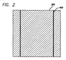
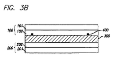
図2は本発明の実施例のプレート型ヒーターの平面図を示している。図3Aはかかるプレート型ヒーターの構造を示す図であり、図3Bはかかるプレート型ヒーターの最終の製造完成図である。 FIG. 2 is a plan view of a plate heater according to an embodiment of the present invention. FIG. 3A is a view showing the structure of such a plate heater, and FIG. 3B is a final completed production view of such a plate heater.
以下では、図2、3Aおよび3Bを参照して説明を行う。 In the following, description will be made with reference to FIGS. 2, 3A and 3B.
本発明の実施例のプレート型ヒーターは、相互に接合された第1外側カバー(101)および第1中間層(102)を含む上側要素(100)と、相互に接合された第2外側カバー(201)および第2中間層(202)を含む下側要素(200)とを有して成り、炭素化合物(300)が上側要素(100)と下側要素(200)との間に配置され、熱発生層(300)の表面に配線(400)が溶融接合されている。 The plate heater according to an embodiment of the present invention includes an upper element (100) including a first outer cover (101) and a first intermediate layer (102) bonded to each other, and a second outer cover ( 201) and a lower element (200) comprising a second intermediate layer (202), the carbon compound (300) being disposed between the upper element (100) and the lower element (200), The wiring (400) is melt bonded to the surface of the heat generating layer (300).
かかる場合、炭素化合物(300)によって電気エネルギーが熱エネルギーに変換され、それによって遠赤外線が放出される。 In such a case, electrical energy is converted into thermal energy by the carbon compound (300), and far infrared rays are thereby emitted.
更に、第1中間層(102)および第2中間層(202)は、熱発生炭素化合物(300)からの電気を遮断し、装置(またはヒーター)の当初の形状を維持する主たる要素として機能している。つまり、第1中間層(102)および第2中間層(202)は、炭素化合物(300)の印刷を改良する絶縁材を成している。 Furthermore, the first intermediate layer (102) and the second intermediate layer (202) function as main elements that block the electricity from the heat generating carbon compound (300) and maintain the original shape of the device (or heater). ing. That is, the first intermediate layer (102) and the second intermediate layer (202) constitute an insulating material that improves the printing of the carbon compound (300).
一方、第1外側カバー(101)および第2外側カバー(201)は、炭素化合物(300)からの電気を遮断し、装置(またはヒーター)の当初の形状を維持する二次的な要素として機能している。第1外側カバー(101)および第2外側カバー(201)は、印刷可能な表面を有するポリオレフィン系材料の外側カバーを形成している。 On the other hand, the first outer cover (101) and the second outer cover (201) function as secondary elements that cut off electricity from the carbon compound (300) and maintain the original shape of the device (or heater). is doing. The first outer cover (101) and the second outer cover (201) form an outer cover of a polyolefin-based material having a printable surface.
また、配線(400)は、接着剤を使用せずに積層によってのみ通電フィルム(通電配線)上の所定位置に固定されている。配線(400)は、導電性材料(たとえば銅)から成るものであってよく、あるいは、実質的に平坦(またはフラット)な形状に押圧(またはプレス)された編組配線(braided wire)であってよい。 Moreover, the wiring (400) is being fixed to the predetermined position on an electricity supply film (energization wiring) only by lamination | stacking, without using an adhesive agent. The wiring (400) may be made of a conductive material (eg, copper), or a braided wire pressed (or pressed) into a substantially flat (or flat) shape. Good.
本発明のプレート型ヒーターの製造方法では、まず、第1外側カバー(101)および第1中間層(102)から成る上側要素(100)と、第2外側カバー(201)および第2中間層(202)から成る下側要素(200)とを製造する。かかる場合、上側要素を構成する第1外側カバー(101)と下側要素を構成する第2外側カバー(201)とは同じ材料から成っており、また、上側要素を構成する第1中間層(102)と下側要素を構成する第2中間層(202)とは同じ材料からなるので、以下の説明では第1外側カバーおよび第1中間層についてのみ説明を行う。 In the manufacturing method of the plate heater of the present invention, first, the upper element (100) composed of the first outer cover (101) and the first intermediate layer (102), the second outer cover (201) and the second intermediate layer ( 202) of the lower element (200). In such a case, the first outer cover (101) constituting the upper element and the second outer cover (201) constituting the lower element are made of the same material, and the first intermediate layer ( 102) and the second intermediate layer (202) constituting the lower element are made of the same material. Therefore, in the following description, only the first outer cover and the first intermediate layer will be described.
第1外側カバー(101)では、耐熱性および熱保持性および寸法安定性を考慮すると、150℃以下の温度で変形することのないポリエチレン(PET)、ポリプロピレン(PP)、ナイロンまたは同様の材料を含む樹脂フィルムが、その耐久性、耐熱性、透明性、印刷特性等の理由でフィルムとして選択される。これらのフィルムはプレート型ヒーターの最外側部の外側カバーとして用いられる。また、これらのフィルムの背面にはロゴや広告宣伝用のスローガンなどが印刷され得る。 In the first outer cover (101), in consideration of heat resistance, heat retention and dimensional stability, polyethylene (PET), polypropylene (PP), nylon or similar material which does not deform at a temperature of 150 ° C. or lower is used. The resin film to be included is selected as a film for reasons such as durability, heat resistance, transparency, and printing characteristics. These films are used as the outer cover of the outermost part of the plate heater. In addition, logos, advertising slogans, and the like can be printed on the back of these films.
尚、第2中間層(102)は、従来のプレート型ヒーターまたはライン型ヒーターには見られない。従来のプレート型ヒーターまたはライン型ヒーターでは、中間層を用いることなく外側カバーフィルムが熱発生層に接着剤を用いて直接的に取り付けられているので(乾燥積層法)、ヒーター自体の絶縁特性や熱保持特性に関して多くの問題を生じ、安定性について極めて深刻な問題が引き起こされる。このような電気的安定性の問題に起因して火災の危険が常に存在している。 The second intermediate layer (102) is not found in the conventional plate type heater or line type heater. In the conventional plate type heater or line type heater, the outer cover film is directly attached to the heat generating layer using an adhesive without using an intermediate layer (dry lamination method). Many problems arise with respect to the heat retention properties, causing very serious problems with stability. Due to such electrical stability problems, there is always a fire hazard.
これらの欠点を改善し、電気絶縁特性および熱保持特性を向上させ、既存の乾燥積層法に関する問題を考慮して安定性を向上させるために、不織布(例えば、ポリエチレンやポリプロピレンなど)、紙またはコットン布が、第1中間層(102)に選択される。通常、これらの材料は、幅が約50cm〜約200cmで使用され、150℃の温度で変形しないものである。 Non-wovens (eg, polyethylene and polypropylene), paper or cotton to improve these deficiencies, improve electrical insulation and heat retention properties, and improve stability taking into account problems with existing dry lamination methods A fabric is selected for the first intermediate layer (102). Typically, these materials are used with a width of about 50 cm to about 200 cm and do not deform at a temperature of 150 ° C.
上述したように、第1外側カバー(101)および第1中間層(102)を接合して上側要素(100)を製作する。ここで、接合に使用される樹脂は100〜170℃の融点を有するポリオレフィン樹脂であるので、かかる樹脂は300℃で溶融する。押出コーティングを個々に又は組み合わせて行い、第1外側カバー(101)と第1中間層(102)とを接合して上側要素(100)の製作を行う。 As described above, the first outer cover (101) and the first intermediate layer (102) are joined to produce the upper element (100). Here, since the resin used for joining is a polyolefin resin having a melting point of 100 to 170 ° C., the resin melts at 300 ° C. Extrusion coating is performed individually or in combination to join the first outer cover (101) and the first intermediate layer (102) to produce the upper element (100).
このような方法を使用することによって、次に、第2外側カバー(201)と第2中間層(202)とを接合して下側要素(200)を製作する。 By using such a method, the second outer cover (201) and the second intermediate layer (202) are then joined to produce the lower element (200).
ここで、外側カバーおよび中間層を接合するのに使用される押出コーティング法(押出積層法)は、あらゆるプレート型ヒーターまたはライン型ヒーターの製造時の接着に際して従来技術で用いられる乾燥積層法とは全く異なる。 Here, the extrusion coating method (extrusion laminating method) used to join the outer cover and the intermediate layer is the dry laminating method used in the prior art for bonding during production of any plate type heater or line type heater. Completely different.
上述したように、最外側カバー(101)および中間層(102)を有して成る上側要素(100)(上側要素の表面には社名ロゴまたはスローガンが印刷される場合がある)と、下側要素(200)(下側要素は使用時に地面に置かれ、スローガンを有していない)とを製作した後、炭素化合物材料(硬化した状態の炭素化合物材料)を下側要素(200)の表面上に配置し、第2炭素化合物(300)を、その導電性および熱発生特性を考慮して、グラビア印刷(gravure printing)によって積層する。尚、グラビア印刷では、グラビア印刷ローラのメッシュサイズを80#〜150#とし、加熱幅に合わせてメッシュ印刷面の幅を50cm〜200cmに調節する。 As described above, the upper element (100) comprising the outermost cover (101) and the middle layer (102) (the company element logo or slogan may be printed on the surface of the upper element) and the lower side After manufacturing the element (200) (the lower element is placed on the ground in use and does not have a slogan), the carbon compound material (cured carbon compound material) is applied to the surface of the lower element (200). Arranged above, the second carbon compound (300) is laminated by gravure printing in view of its conductivity and heat generation characteristics. In the gravure printing, the mesh size of the gravure printing roller is set to 80 # to 150 #, and the width of the mesh printing surface is adjusted to 50 cm to 200 cm according to the heating width.
ヒーター製造に常套的に使用される印刷法はスクリーン印刷法である。スクリーン印刷法では積層印刷ができないので、高粘度インクを用いて、スクリーン印刷法による印刷の後に、最外側カバーを乾燥積層法によって取り付けていた。しかしながら、導電率および熱量を粘度によって調節しなければならず、かかる調節を正確に行うことは非常に困難である。従って、製造される製品はシンプルなものとなってしまう。 A printing method conventionally used in the manufacture of heaters is the screen printing method. Since screen printing cannot be used for lamination printing, the outermost cover was attached by dry lamination after printing by screen printing using high viscosity ink. However, the conductivity and amount of heat must be adjusted by viscosity, and it is very difficult to make such adjustment accurately. Accordingly, the manufactured product is simple.
これを補うために、本発明の場合のようにグラビア印刷法を用いる場合、炭素複合化合物(300)の濃度および積層の厚さを考慮することになり、単層または多層から成る積層を顧客の要求および目的とする用途に応じて行うことができる。印刷ローラのメッシュサイズを調節することによって、より正確な調節を行うことができる。この場合に重要な事項について言えば、80メッシュ以下のサイズでは、インクがにじみ、精密な製品製造を困難にする一方で、150以上のメッシュサイズでは、インクが十分に適用されず、製品製造を不可能にする。従って、本発明のグラビア印刷法では、あらゆる場合において、80#〜150#のメッシュサイズで製造を行う必要がある。これにより、いかなる条件下であっても、必要とされる導電性および熱量の調節が可能となる。 In order to compensate for this, when using the gravure printing method as in the present invention, the concentration of the carbon composite compound (300) and the thickness of the stack will be taken into account. This can be done according to the requirements and intended use. More accurate adjustments can be made by adjusting the mesh size of the printing roller. In this case, if the size is 80 mesh or less, the ink bleeds and it is difficult to manufacture a precise product. On the other hand, if the mesh size is 150 mesh or more, the ink is not sufficiently applied and the product is manufactured. Make impossible. Therefore, in the gravure printing method of the present invention, it is necessary to manufacture with a mesh size of 80 # to 150 # in all cases. This makes it possible to adjust the required conductivity and heat quantity under any conditions.
上述したように上側要素(100)および下側要素(200)の製作が完了し、これに炭素化合物(300)を設けた後、上側要素(100)と下側要素(200)とを接合してプレート型ヒーターを完成させる。10本以上の薄い撚り合された銅線のストランドから成り、2〜3mm、より好ましくは2〜2.3mmの外径を有する通電配線または通電編組配線(400)を埋め込むために、任意に穴を空けた銅板完成品を、ポリオレフィン樹脂を用いて溶解させて積層された炭素化合物(300)の端部(または必要なら炭素化合物の中央)に取り付け、押出積層法(または押出ラミネーション、extrusion lamination method)によって接合し完成させる。 After the fabrication of the upper element (100) and the lower element (200) is completed as described above and the carbon compound (300) is provided thereon, the upper element (100) and the lower element (200) are joined. Complete the plate heater. To embed energized wiring or energized braided wiring (400) consisting of 10 or more thin twisted strands of copper wire and having an outer diameter of 2-3 mm, more preferably 2-2.3 mm, an optional hole The finished copper plate with a gap is attached to the end of the carbon compound (300) (or the center of the carbon compound, if necessary) dissolved and laminated using polyolefin resin, and extrusion lamination (or extrusion lamination method) ) To complete.
本発明では、既存のプレート(ライン)型ヒーターの欠点(即ち、導電性接着剤を用いる際の通電フィルムに対する接着に起因した問題)を解決するために、配線(400)を接着剤を用いずに単に積層によって所定の位置に固定している、このように配線(400)を固定するために、全体で約2〜3mm以上(フラットなストリップ配線または薄い編組配線(撚られた配線))の直径を有する配線をできるだけフラットな形状となるように圧縮処理して使用する。炭素化合物(300)の設置面に接着させる面を広くするために、または、製造に際して表面から突出する領域を最小限にして審美的に好ましい外観を維持するために、配線を平坦な形状にまで処理する。 In the present invention, in order to solve the drawbacks of the existing plate (line) type heater (that is, the problem caused by adhesion to the current-carrying film when using a conductive adhesive), the wiring (400) is not used as an adhesive. In order to fix the wiring (400) in this way, the total of about 2 to 3 mm (flat strip wiring or thin braided wiring (twisted wiring)) A wire having a diameter is used after being compressed so as to be as flat as possible. In order to widen the surface to be bonded to the installation surface of the carbon compound (300), or to maintain an aesthetically pleasing appearance while minimizing the area protruding from the surface during manufacture, the wiring is made flat. To process.
上述したように、全体の幅は目的とする用途に応じて調節することができる。より具体的には、配線(400)の厚さを調節することによって、1メートル以上(かつ100メートル以下)の最小構造幅を有する製品を切断することなく製造できる。 As described above, the overall width can be adjusted according to the intended application. More specifically, by adjusting the thickness of the wiring (400), a product having a minimum structure width of 1 meter or more (and 100 meters or less) can be manufactured without cutting.
プレート型ヒーターの幅は大きくなければならないが、高温を要する場合には、より厚い配線を用いてもよい。使用電圧としては交流(AC)か直流(DC)のいずれかを使用できる。電圧範囲は6V〜400Vが好ましい。更に、導電率は0〜102であり、電気抵抗は0〜900Ωであり、炭素化合物の適用厚さは10〜100μmであり、熱発生幅は50〜200cmであり、遠赤外線パーセンテージ(far infrared radiation percentage)は87.5%である。 The width of the plate heater must be large, but thicker wiring may be used when high temperatures are required. As the working voltage, either alternating current (AC) or direct current (DC) can be used. The voltage range is preferably 6V to 400V. Furthermore, electric conductivity was 0-10 2, the electrical resistance is 0~900Omu, applied thickness of the carbon compound is 10 to 100 [mu] m, the heat generation width is 50 to 200 cm, far infrared percentage (_far infrared radiation percentage) is 87.5%.
本発明のプレート型ヒーターの炭素化合物(遠赤外線伝導性インク)のおおよその組成は、30.4%のウレタンポリマー樹脂、15.6%の導電性粉末(例えば、炭素ポリマー)、4%の添加剤(例えば、接着剤)、および50%の希釈溶剤(例えば、水または希釈剤)となっている。 The approximate composition of the carbon compound (far-infrared conductive ink) of the plate-type heater of the present invention is 30.4% urethane polymer resin, 15.6% conductive powder (for example, carbon polymer), 4% addition Agent (eg, adhesive) and 50% diluent solvent (eg, water or diluent).
図4は、本発明の実施例におけるプレート型ヒーターの仕様例を示す。これとは異なるサイズのものを同様に製造してもよい。 FIG. 4 shows a specification example of the plate heater in the embodiment of the present invention. Different sizes may be produced in the same way.
図4に示すように、プレート型ヒーターの全体の幅(A)は100cmである。そして、電流を加えた際に熱を発生する部分の幅(B)は45cmであり、電流を加えた際に熱を発生しない部分の幅(C)は47cmである。電流も通さず、熱も発生しない残りの部分の幅(D)は1.5cmである。 As shown in FIG. 4, the overall width (A) of the plate heater is 100 cm. The width (B) of the portion that generates heat when current is applied is 45 cm, and the width (C) of the portion that does not generate heat when current is applied is 47 cm. The width (D) of the remaining portion through which no current flows and no heat is generated is 1.5 cm.
全幅のうち半分のみが必要な場合には、製品を中央(E)で切断して使用することができ、これは電気的観点からは何の問題も引き起こすものでない。 If only half of the full width is required, the product can be cut and used at the center (E), which does not cause any problems from an electrical point of view.
上述したように、本発明では、ライン型ヒーターに比べて、表面全体にわたって容易に電流および熱が発生するので、熱量の半分を用いて全表面を均一に加熱することができる。それゆえ、無駄がなく、通電領域となる配線を、用途や懸案の表面領域が求める薄い厚さとなるようにできる。 As described above, in the present invention, since current and heat are easily generated over the entire surface as compared with the line heater, the entire surface can be uniformly heated using half the amount of heat. Therefore, there is no waste, and the wiring that becomes the energization region can be made as thin as required by the surface region of the application and the problem.
更に、配線に対して接着剤を使用しないので、時間の経過に伴って炭化現象が発生するという可能性が低くなり、配線の厚さを調節することができるので、加熱に起因する火災の危険性がない。 In addition, since no adhesive is used for the wiring, the possibility of carbonization over time decreases, and the thickness of the wiring can be adjusted, so there is a risk of fire caused by heating. There is no sex.
切断または接続することなく本発明を利用することができるので、ライン型ヒーターと比べて、操作はシンプルかつ容易であり、生じる熱および遠赤外線は全表面積に基づいて約2倍の増加となり得る。 Since the present invention can be utilized without disconnection or connection, operation is simple and easy compared to line heaters, and the resulting heat and far infrared can be increased by a factor of about 2 based on total surface area.
更に、他の熱電式導電体を必要としないので、ラミネート紙で覆われたフロアの場合および誘導電流がヒーターにて発生する場合に本発明を利用することができる。その場合、かかる電流は、シールドを用いることおよび装置を接地することによって完全に取り除くことができる。 Furthermore, since no other thermoelectric conductor is required, the present invention can be used in the case of a floor covered with laminated paper and when an induced current is generated by a heater. In that case, such current can be completely removed by using a shield and grounding the device.
電磁波の発生する程度も比較的低く、炭素化合物が実質的に損傷を受けることなく電磁波を吸収する。 The degree of generation of electromagnetic waves is relatively low, and the carbon compound absorbs electromagnetic waves without being substantially damaged.
押出積層法では接着剤ではなくポリオレフィン樹脂を用いるので、通電銅フィルムの厚さは用途および対象とする条件に基づいて選択することができ、幅の大きい製品(従来技術のライン型ヒーターの幅の5倍までの幅を有する製品)も製造することができる。 Since the extrusion lamination method uses polyolefin resin instead of adhesive, the thickness of the current-carrying copper film can be selected based on the application and target conditions. Products with a width up to 5 times) can also be produced.
本発明のプレート型ヒーターに用いられる炭素化合物中の炭素は、多くの応用例(または適用)および特性を有することで周知であり、熱についての利点だけでなく、遠赤外線についての利点も備えており、例えば、電磁波の吸収、脱臭、重金属の吸収、遠赤外線の発生、湿度の調節、バクテリアの除去、農薬や酸性化の影響の防止およびアニオンの生成といったような効果を有している。 The carbon in the carbon compound used in the plate heater of the present invention is well known for having many applications (or applications) and properties, and has not only advantages for heat but also advantages for far infrared. For example, it has effects such as absorption of electromagnetic waves, deodorization, absorption of heavy metals, generation of far infrared rays, adjustment of humidity, removal of bacteria, prevention of the effects of agricultural chemicals and acidification, and generation of anions.
炭素を上述したように熱発生物質として使用する場合、電気抵抗加熱要素を介して少ない電気エネルギーを用いて多くの熱量を得ることができるので、未来志向のエネルギー用途に用いることができる。例えば、発明を、米や野菜の稚苗等の育成、乾燥(遠赤外線乾燥および乾燥後の再給湿に際して原型の80%が回復する殺菌作用)、マッシュルーム育成、畜産、寝具(ヘルスベッドおよびフロアクッション)、構造物(加熱材)、および食料品(ローストした肉や魚の家庭での食品加工)等の領域に適用することができる。 When carbon is used as a heat generating material as described above, a large amount of heat can be obtained using a small amount of electric energy via an electric resistance heating element, and therefore it can be used for future-oriented energy applications. For example, the invention can be applied to breeding seedlings of rice and vegetables, drying (disinfection action that recovers 80% of the original form during far-infrared drying and rehumidification after drying), mushroom breeding, livestock, bedding (health bed and floor It can be applied to areas such as cushions), structures (heating materials), and food products (food processing at home for roasted meat and fish).
以下の表1では、本発明の実施例のプレート型ヒーターを使用した場合と個々の加熱材を使用した場合とのエネルギー消費量が比較されている。 In Table 1 below, energy consumption is compared between the case where the plate heater of the embodiment of the present invention is used and the case where individual heating materials are used.

2)韓国ウォン基準
2) Korean won standards
表1は、1日当たり8時間の作動を30日間行ったものである(外部温度が0℃に維持され、内部温度が22℃に維持された)。 Table 1 shows the operation for 8 hours per day for 30 days (the external temperature was maintained at 0 ° C. and the internal temperature was maintained at 22 ° C.).
表1から分かるように、プレート型ヒーターを使用した場合、単位pyong当たりの加熱コストを大きく減少させることができ、同様のユニットを使用した1ヶ月の深夜の消費電力と比べて、約半分の低減を達成することができる。 As can be seen from Table 1, when a plate heater is used, the heating cost per unit of pyong can be greatly reduced, and it is reduced by about half compared to the power consumption in the middle of the night using the same unit. Can be achieved.
好ましい実施例に従って本発明の技術的概念について具体的に説明してきたが、かかる実施例は単に例示にすぎず、本発明を限定するものではないことに留意されたい。更に、本発明の分野の当業者は、本発明の技術的概念の範囲から外れることなく多くの実施例が可能であることを理解されるであろう。 Although the technical concepts of the present invention have been specifically described according to preferred embodiments, it should be noted that such embodiments are merely illustrative and do not limit the present invention. Further, those skilled in the art of the present invention will appreciate that many embodiments are possible without departing from the scope of the technical concept of the present invention.
本発明では全面ヒーター構造を有するプレート型ヒーターが提供されるので、発生する熱量または遠赤外線量を増加させることが可能であるといった効果を有している。 In the present invention, since a plate-type heater having a full-surface heater structure is provided, the amount of generated heat or far-infrared rays can be increased.
また、本発明は、接着法を用いるのではなく押出積層法によって、通電フィルムの取付けを行うので、幅の大きい製品を製造することが可能であるといった効果も有している。 In addition, the present invention has an effect that it is possible to manufacture a product having a large width because the current-carrying film is attached by an extrusion lamination method rather than using an adhesion method.
本発明のプレート型ヒーターは、マット、ベッド、ベッドマットレス、電気キルトおよび毛布、ならびに、アパートおよび一般住宅住居の住宅用加熱デバイス等に幅広く使用される。更に、本発明のプレート型ヒーターは、オフィスおよび店舗などの商業用建物のためのヒーター、工場、倉庫およびバラックのための産業用ヒーター、更には工業用途のヒーター、および、農業設備(例えば、農産物用のビニールハウスおよび乾燥システム)のためのヒーターに使用されていたり、種々の凍結防止システム(例えば、雪を融かし道路や駐車場の凍結を防止するための装置)にも使用される。また、プレート型ヒーターは、レクリエーション用途、防寒用途、家庭用電気器具の用途、鏡やガラス上に蒸気が形成されるのを防止する装置の用途、ヘルスケア用途、家畜の飼育等の用途も有している。 The plate heater of the present invention is widely used for mats, beds, bed mattresses, electric quilts and blankets, and heating devices for residential use in apartments and general dwellings. Further, the plate heater of the present invention is a heater for commercial buildings such as offices and stores, an industrial heater for factories, warehouses and barracks, and an industrial heater, and agricultural equipment (eg, agricultural products). Used in heaters for commercial greenhouses and drying systems) and in various anti-freezing systems (for example, devices for melting snow and preventing roads and parking lots from freezing). Plate heaters are also used for recreational applications, cold protection applications, household appliances, devices that prevent the formation of vapor on mirrors and glass, healthcare applications, livestock breeding, etc. is doing.
100:上側要素
101:第1外側カバー
102:第1中間層
200:下側要素
201:第2外側カバー
202:第2中間層
300:炭素化合物
400:配線(または電線)
100: upper element 101: first outer cover 102: first intermediate layer 200: lower element 201: second outer cover 202: second intermediate layer 300: carbon compound 400: wiring (or electric wire)
Claims (17)
接合された第2外側カバーおよび第2中間層から成る下側要素、
上側要素と下側要素との間に配置された加熱要素、および
加熱要素の両端部の表面上に積層された配線
を有して成るプレート型ヒーター。 An upper element comprising a joined first outer cover and a first intermediate layer;
A lower element comprising a joined second outer cover and a second intermediate layer;
A plate-type heater comprising: a heating element disposed between an upper element and a lower element; and wiring laminated on surfaces of both ends of the heating element.
接合された外側カバーと中間層とから成る上側要素および下側要素を製造すること、
下側要素の上部表面全体に加熱要素を設けること、
電気エネルギーの供給に使用する配線を加熱要素の端部に積層させて取り付けること、および
加熱要素を設けた下側要素を上側要素に接合させること
を含んで成る製造方法。 A method of manufacturing a plate heater,
Manufacturing an upper element and a lower element consisting of a joined outer cover and an intermediate layer;
Providing a heating element over the entire upper surface of the lower element;
A manufacturing method comprising: stacking and attaching wiring used for supplying electric energy to an end of a heating element; and joining a lower element provided with the heating element to an upper element.
Applications Claiming Priority (2)
| Application Number | Priority Date | Filing Date | Title |
|---|---|---|---|
| KR1020050062812A KR100750707B1 (en) | 2004-07-12 | 2005-07-12 | Plate heater and method for manufacturing the same |
| PCT/US2006/026639 WO2007008734A2 (en) | 2005-07-12 | 2006-07-07 | A plate-type heater and a method for the manufacture thereof |
Publications (1)
| Publication Number | Publication Date |
|---|---|
| JP2009507330A true JP2009507330A (en) | 2009-02-19 |
Family
ID=39615593
Family Applications (1)
| Application Number | Title | Priority Date | Filing Date |
|---|---|---|---|
| JP2008521478A Pending JP2009507330A (en) | 2005-07-12 | 2006-07-07 | Plate type heater and manufacturing method thereof |
Country Status (8)
| Country | Link |
|---|---|
| US (1) | US8138457B2 (en) |
| EP (1) | EP1907759B1 (en) |
| JP (1) | JP2009507330A (en) |
| CN (1) | CN101496445B (en) |
| AU (1) | AU2006269207A1 (en) |
| CA (1) | CA2615156C (en) |
| ES (1) | ES2522282T3 (en) |
| WO (1) | WO2007008734A2 (en) |
Cited By (1)
| Publication number | Priority date | Publication date | Assignee | Title |
|---|---|---|---|---|
| KR101576545B1 (en) * | 2014-04-25 | 2015-12-11 | (주) 파루 | Heating mat using electromagnetic shielding film |
Families Citing this family (10)
| Publication number | Priority date | Publication date | Assignee | Title |
|---|---|---|---|---|
| US8575523B2 (en) * | 2008-04-25 | 2013-11-05 | Innovative Heating Technologies Inc | Planar heating element for underfloor heating |
| EP2281579A1 (en) | 2009-08-05 | 2011-02-09 | BioNTech AG | Vaccine composition comprising 5'-Cap modified RNA |
| CN102162294B (en) * | 2010-02-23 | 2013-03-20 | 北京富纳特创新科技有限公司 | Heating floor tile and heating floor using the same |
| CA2724165A1 (en) | 2010-12-02 | 2012-06-02 | Alternative Heating Systems Inc. | Electrical safety grounding system |
| US10201039B2 (en) * | 2012-01-20 | 2019-02-05 | Gentherm Gmbh | Felt heater and method of making |
| CN103982010B (en) * | 2014-05-30 | 2016-08-24 | 唐山德生防水股份有限公司 | Gutter snow melting waterproof roll |
| CN106162957A (en) * | 2016-09-07 | 2016-11-23 | 芜湖桑乐金电子科技有限公司 | Fire-retardant carbon crystal heating panel and preparation method thereof |
| CN106455153A (en) * | 2016-09-07 | 2017-02-22 | 芜湖桑乐金电子科技有限公司 | Flame-retardant carbon crystal heating plate and preparation method thereof |
| CN106413150A (en) * | 2016-09-07 | 2017-02-15 | 芜湖桑乐金电子科技有限公司 | High-tenacity carbon crystal heating plate and preparation method thereof |
| DE102017001513A1 (en) * | 2017-02-17 | 2018-08-23 | K. L. Kaschier- Und Laminier Gmbh | Lens hood of an image acquisition device |
Citations (6)
| Publication number | Priority date | Publication date | Assignee | Title |
|---|---|---|---|---|
| EP0409393A2 (en) * | 1989-07-17 | 1991-01-23 | Metal Manufactures Limited | Heating mats |
| JPH0589952A (en) | 1991-09-30 | 1993-04-09 | Dainippon Ink & Chem Inc | Manufacture of planar heating element |
| JPH06281174A (en) | 1993-03-30 | 1994-10-07 | Toyo Tire & Rubber Co Ltd | Floor heating panel |
| JPH08111282A (en) | 1994-10-11 | 1996-04-30 | Idemitsu Kosan Co Ltd | Multi-layer sheet form heater and method for covering exterior sheet |
| JP2000086872A (en) | 1998-09-17 | 2000-03-28 | Ougi Kagaku Kogyo Kk | Resin composition having ptc characteristic |
| JP2001267042A (en) * | 2000-03-22 | 2001-09-28 | Minato Giken:Kk | Planar heating element |
Family Cites Families (4)
| Publication number | Priority date | Publication date | Assignee | Title |
|---|---|---|---|---|
| JPS522915Y2 (en) * | 1972-02-09 | 1977-01-22 | ||
| CA1314581C (en) * | 1988-07-08 | 1993-03-16 | Yoshinori Nishino | Heater device used for floor material etc. and floor material with heater contained therein |
| US6263158B1 (en) * | 1999-05-11 | 2001-07-17 | Watlow Polymer Technologies | Fibrous supported polymer encapsulated electrical component |
| CN1183805C (en) * | 1999-12-10 | 2005-01-05 | 热离子体系国际公司 | Thermoplastic laminate fabric heater and methods for making same |
-
2006
- 2006-07-07 JP JP2008521478A patent/JP2009507330A/en active Pending
- 2006-07-07 ES ES06786703.6T patent/ES2522282T3/en active Active
- 2006-07-07 CA CA2615156A patent/CA2615156C/en active Active
- 2006-07-07 US US11/995,226 patent/US8138457B2/en not_active Expired - Fee Related
- 2006-07-07 AU AU2006269207A patent/AU2006269207A1/en not_active Abandoned
- 2006-07-07 WO PCT/US2006/026639 patent/WO2007008734A2/en active Application Filing
- 2006-07-07 EP EP06786703.6A patent/EP1907759B1/en not_active Not-in-force
- 2006-07-07 CN CN200680033428XA patent/CN101496445B/en not_active Expired - Fee Related
Patent Citations (6)
| Publication number | Priority date | Publication date | Assignee | Title |
|---|---|---|---|---|
| EP0409393A2 (en) * | 1989-07-17 | 1991-01-23 | Metal Manufactures Limited | Heating mats |
| JPH0589952A (en) | 1991-09-30 | 1993-04-09 | Dainippon Ink & Chem Inc | Manufacture of planar heating element |
| JPH06281174A (en) | 1993-03-30 | 1994-10-07 | Toyo Tire & Rubber Co Ltd | Floor heating panel |
| JPH08111282A (en) | 1994-10-11 | 1996-04-30 | Idemitsu Kosan Co Ltd | Multi-layer sheet form heater and method for covering exterior sheet |
| JP2000086872A (en) | 1998-09-17 | 2000-03-28 | Ougi Kagaku Kogyo Kk | Resin composition having ptc characteristic |
| JP2001267042A (en) * | 2000-03-22 | 2001-09-28 | Minato Giken:Kk | Planar heating element |
Cited By (1)
| Publication number | Priority date | Publication date | Assignee | Title |
|---|---|---|---|---|
| KR101576545B1 (en) * | 2014-04-25 | 2015-12-11 | (주) 파루 | Heating mat using electromagnetic shielding film |
Also Published As
| Publication number | Publication date |
|---|---|
| CA2615156C (en) | 2015-04-07 |
| WO2007008734A3 (en) | 2009-03-26 |
| EP1907759B1 (en) | 2014-08-13 |
| US20080264929A1 (en) | 2008-10-30 |
| WO2007008734A2 (en) | 2007-01-18 |
| US8138457B2 (en) | 2012-03-20 |
| EP1907759A2 (en) | 2008-04-09 |
| CN101496445B (en) | 2012-06-20 |
| EP1907759A4 (en) | 2010-03-24 |
| AU2006269207A1 (en) | 2007-01-18 |
| WO2007008734A8 (en) | 2008-07-17 |
| ES2522282T3 (en) | 2014-11-14 |
| CN101496445A (en) | 2009-07-29 |
| CA2615156A1 (en) | 2007-01-18 |
Similar Documents
| Publication | Publication Date | Title |
|---|---|---|
| JP2009507330A (en) | Plate type heater and manufacturing method thereof | |
| US8304694B2 (en) | Electric heating material and laminate floor containing same and method for producing the laminate floor | |
| KR100750707B1 (en) | Plate heater and method for manufacturing the same | |
| KR101180037B1 (en) | A film heater that can be controled by a independent cell | |
| CA2235697C (en) | Heating apparatus | |
| CN103687098A (en) | PTC (Positive Temperature Coefficient) heating sheet, low-temperature radiating electrothermal film and preparation method of low-temperature radiating electrothermal film | |
| KR100491225B1 (en) | Surface type heater which emits infrared rays | |
| CN202148667U (en) | Wiring structure of electric hot plate of electric floor heating system | |
| KR20100087907A (en) | Film heater with improved stability and its manufacturing method | |
| CN201255464Y (en) | Dry-type floor warming device | |
| WO2008063173A1 (en) | A method for manufacturing a plate-type heater | |
| CN212086511U (en) | Electroluminescence thin film | |
| KR100813928B1 (en) | Method for fabricating plate heater | |
| KR20080079517A (en) | Dry laminated type apparatus for manufacturing plate heater | |
| KR101171470B1 (en) | Method for fabricating low voltage plane heating sheet and plane heating sheet fabricated using the same | |
| KR100783184B1 (en) | Method for producing of heating fabrics for AC ? DC power | |
| JP3997179B2 (en) | Linear / planar heating elements and snow melting mats and hotbed mats with linear / planar heating elements | |
| KR200247329Y1 (en) | Far-infrared radiating sheet heater | |
| KR101766581B1 (en) | The electrical heating matt of far infrared emission | |
| CN208241919U (en) | Electroluminescent heating film | |
| CN107809811A (en) | One kind is without metal heater element and heating pad | |
| KR20070054134A (en) | Method for fabricating plate heater | |
| CN202692216U (en) | Floor heating system | |
| JP2000283482A (en) | Laminate having heating function and structure for taking out electrode part | |
| KR20110002203A (en) | Plane heater of wiring type make use of polyethylene pet and a manufacturing method of it |
Legal Events
| Date | Code | Title | Description |
|---|---|---|---|
| A621 | Written request for application examination |
Free format text: JAPANESE INTERMEDIATE CODE: A621 Effective date: 20090703 |
|
| A131 | Notification of reasons for refusal |
Free format text: JAPANESE INTERMEDIATE CODE: A131 Effective date: 20111129 |
|
| A601 | Written request for extension of time |
Free format text: JAPANESE INTERMEDIATE CODE: A601 Effective date: 20120228 |
|
| A602 | Written permission of extension of time |
Free format text: JAPANESE INTERMEDIATE CODE: A602 Effective date: 20120306 |
|
| A601 | Written request for extension of time |
Free format text: JAPANESE INTERMEDIATE CODE: A601 Effective date: 20120327 |
|
| A602 | Written permission of extension of time |
Free format text: JAPANESE INTERMEDIATE CODE: A602 Effective date: 20120403 |
|
| A02 | Decision of refusal |
Free format text: JAPANESE INTERMEDIATE CODE: A02 Effective date: 20121023 |
|
| A521 | Written amendment |
Free format text: JAPANESE INTERMEDIATE CODE: A523 Effective date: 20130225 |
|
| A911 | Transfer to examiner for re-examination before appeal (zenchi) |
Free format text: JAPANESE INTERMEDIATE CODE: A911 Effective date: 20130408 |
|
| A912 | Re-examination (zenchi) completed and case transferred to appeal board |
Free format text: JAPANESE INTERMEDIATE CODE: A912 Effective date: 20130705 |
|
| A601 | Written request for extension of time |
Free format text: JAPANESE INTERMEDIATE CODE: A601 Effective date: 20131022 |
|
| A602 | Written permission of extension of time |
Free format text: JAPANESE INTERMEDIATE CODE: A602 Effective date: 20131028 |
|
| A601 | Written request for extension of time |
Free format text: JAPANESE INTERMEDIATE CODE: A601 Effective date: 20131121 |
|
| A602 | Written permission of extension of time |
Free format text: JAPANESE INTERMEDIATE CODE: A602 Effective date: 20131126 |
|
| A601 | Written request for extension of time |
Free format text: JAPANESE INTERMEDIATE CODE: A601 Effective date: 20131219 |
|
| A602 | Written permission of extension of time |
Free format text: JAPANESE INTERMEDIATE CODE: A602 Effective date: 20131225 |
|
| A601 | Written request for extension of time |
Free format text: JAPANESE INTERMEDIATE CODE: A601 Effective date: 20140711 |
|
| A602 | Written permission of extension of time |
Free format text: JAPANESE INTERMEDIATE CODE: A602 Effective date: 20140716 |
|
| A601 | Written request for extension of time |
Free format text: JAPANESE INTERMEDIATE CODE: A601 Effective date: 20140811 |
|
| A602 | Written permission of extension of time |
Free format text: JAPANESE INTERMEDIATE CODE: A602 Effective date: 20140818 |
|
| A601 | Written request for extension of time |
Free format text: JAPANESE INTERMEDIATE CODE: A601 Effective date: 20140912 |
|
| A602 | Written permission of extension of time |
Free format text: JAPANESE INTERMEDIATE CODE: A602 Effective date: 20140919 |