JP2009506263A - Expandable wave energy conversion system - Google Patents
Expandable wave energy conversion system Download PDFInfo
- Publication number
- JP2009506263A JP2009506263A JP2008529191A JP2008529191A JP2009506263A JP 2009506263 A JP2009506263 A JP 2009506263A JP 2008529191 A JP2008529191 A JP 2008529191A JP 2008529191 A JP2008529191 A JP 2008529191A JP 2009506263 A JP2009506263 A JP 2009506263A
- Authority
- JP
- Japan
- Prior art keywords
- float
- wave energy
- energy converter
- envelope
- water
- Prior art date
- Legal status (The legal status is an assumption and is not a legal conclusion. Google has not performed a legal analysis and makes no representation as to the accuracy of the status listed.)
- Pending
Links
Images


Classifications
-
- F—MECHANICAL ENGINEERING; LIGHTING; HEATING; WEAPONS; BLASTING
- F03—MACHINES OR ENGINES FOR LIQUIDS; WIND, SPRING, OR WEIGHT MOTORS; PRODUCING MECHANICAL POWER OR A REACTIVE PROPULSIVE THRUST, NOT OTHERWISE PROVIDED FOR
- F03B—MACHINES OR ENGINES FOR LIQUIDS
- F03B13/00—Adaptations of machines or engines for special use; Combinations of machines or engines with driving or driven apparatus; Power stations or aggregates
- F03B13/12—Adaptations of machines or engines for special use; Combinations of machines or engines with driving or driven apparatus; Power stations or aggregates characterised by using wave or tide energy
- F03B13/14—Adaptations of machines or engines for special use; Combinations of machines or engines with driving or driven apparatus; Power stations or aggregates characterised by using wave or tide energy using wave energy
- F03B13/16—Adaptations of machines or engines for special use; Combinations of machines or engines with driving or driven apparatus; Power stations or aggregates characterised by using wave or tide energy using wave energy using the relative movement between a wave-operated member, i.e. a "wom" and another member, i.e. a reaction member or "rem"
- F03B13/18—Adaptations of machines or engines for special use; Combinations of machines or engines with driving or driven apparatus; Power stations or aggregates characterised by using wave or tide energy using wave energy using the relative movement between a wave-operated member, i.e. a "wom" and another member, i.e. a reaction member or "rem" where the other member, i.e. rem is fixed, at least at one point, with respect to the sea bed or shore
- F03B13/1805—Adaptations of machines or engines for special use; Combinations of machines or engines with driving or driven apparatus; Power stations or aggregates characterised by using wave or tide energy using wave energy using the relative movement between a wave-operated member, i.e. a "wom" and another member, i.e. a reaction member or "rem" where the other member, i.e. rem is fixed, at least at one point, with respect to the sea bed or shore and the wom is hinged to the rem
- F03B13/181—Adaptations of machines or engines for special use; Combinations of machines or engines with driving or driven apparatus; Power stations or aggregates characterised by using wave or tide energy using wave energy using the relative movement between a wave-operated member, i.e. a "wom" and another member, i.e. a reaction member or "rem" where the other member, i.e. rem is fixed, at least at one point, with respect to the sea bed or shore and the wom is hinged to the rem for limited rotation
- F03B13/1815—Adaptations of machines or engines for special use; Combinations of machines or engines with driving or driven apparatus; Power stations or aggregates characterised by using wave or tide energy using wave energy using the relative movement between a wave-operated member, i.e. a "wom" and another member, i.e. a reaction member or "rem" where the other member, i.e. rem is fixed, at least at one point, with respect to the sea bed or shore and the wom is hinged to the rem for limited rotation with an up-and-down movement
-
- F—MECHANICAL ENGINEERING; LIGHTING; HEATING; WEAPONS; BLASTING
- F03—MACHINES OR ENGINES FOR LIQUIDS; WIND, SPRING, OR WEIGHT MOTORS; PRODUCING MECHANICAL POWER OR A REACTIVE PROPULSIVE THRUST, NOT OTHERWISE PROVIDED FOR
- F03B—MACHINES OR ENGINES FOR LIQUIDS
- F03B13/00—Adaptations of machines or engines for special use; Combinations of machines or engines with driving or driven apparatus; Power stations or aggregates
- F03B13/12—Adaptations of machines or engines for special use; Combinations of machines or engines with driving or driven apparatus; Power stations or aggregates characterised by using wave or tide energy
- F03B13/14—Adaptations of machines or engines for special use; Combinations of machines or engines with driving or driven apparatus; Power stations or aggregates characterised by using wave or tide energy using wave energy
- F03B13/16—Adaptations of machines or engines for special use; Combinations of machines or engines with driving or driven apparatus; Power stations or aggregates characterised by using wave or tide energy using wave energy using the relative movement between a wave-operated member, i.e. a "wom" and another member, i.e. a reaction member or "rem"
- F03B13/18—Adaptations of machines or engines for special use; Combinations of machines or engines with driving or driven apparatus; Power stations or aggregates characterised by using wave or tide energy using wave energy using the relative movement between a wave-operated member, i.e. a "wom" and another member, i.e. a reaction member or "rem" where the other member, i.e. rem is fixed, at least at one point, with respect to the sea bed or shore
- F03B13/1845—Adaptations of machines or engines for special use; Combinations of machines or engines with driving or driven apparatus; Power stations or aggregates characterised by using wave or tide energy using wave energy using the relative movement between a wave-operated member, i.e. a "wom" and another member, i.e. a reaction member or "rem" where the other member, i.e. rem is fixed, at least at one point, with respect to the sea bed or shore and the wom slides relative to the rem
- F03B13/1875—Adaptations of machines or engines for special use; Combinations of machines or engines with driving or driven apparatus; Power stations or aggregates characterised by using wave or tide energy using wave energy using the relative movement between a wave-operated member, i.e. a "wom" and another member, i.e. a reaction member or "rem" where the other member, i.e. rem is fixed, at least at one point, with respect to the sea bed or shore and the wom slides relative to the rem and the wom is the piston or the cylinder in a pump
-
- F—MECHANICAL ENGINEERING; LIGHTING; HEATING; WEAPONS; BLASTING
- F03—MACHINES OR ENGINES FOR LIQUIDS; WIND, SPRING, OR WEIGHT MOTORS; PRODUCING MECHANICAL POWER OR A REACTIVE PROPULSIVE THRUST, NOT OTHERWISE PROVIDED FOR
- F03B—MACHINES OR ENGINES FOR LIQUIDS
- F03B13/00—Adaptations of machines or engines for special use; Combinations of machines or engines with driving or driven apparatus; Power stations or aggregates
- F03B13/12—Adaptations of machines or engines for special use; Combinations of machines or engines with driving or driven apparatus; Power stations or aggregates characterised by using wave or tide energy
- F03B13/14—Adaptations of machines or engines for special use; Combinations of machines or engines with driving or driven apparatus; Power stations or aggregates characterised by using wave or tide energy using wave energy
- F03B13/16—Adaptations of machines or engines for special use; Combinations of machines or engines with driving or driven apparatus; Power stations or aggregates characterised by using wave or tide energy using wave energy using the relative movement between a wave-operated member, i.e. a "wom" and another member, i.e. a reaction member or "rem"
- F03B13/18—Adaptations of machines or engines for special use; Combinations of machines or engines with driving or driven apparatus; Power stations or aggregates characterised by using wave or tide energy using wave energy using the relative movement between a wave-operated member, i.e. a "wom" and another member, i.e. a reaction member or "rem" where the other member, i.e. rem is fixed, at least at one point, with respect to the sea bed or shore
- F03B13/188—Adaptations of machines or engines for special use; Combinations of machines or engines with driving or driven apparatus; Power stations or aggregates characterised by using wave or tide energy using wave energy using the relative movement between a wave-operated member, i.e. a "wom" and another member, i.e. a reaction member or "rem" where the other member, i.e. rem is fixed, at least at one point, with respect to the sea bed or shore and the wom is flexible or deformable
-
- B—PERFORMING OPERATIONS; TRANSPORTING
- B63—SHIPS OR OTHER WATERBORNE VESSELS; RELATED EQUIPMENT
- B63B—SHIPS OR OTHER WATERBORNE VESSELS; EQUIPMENT FOR SHIPPING
- B63B35/00—Vessels or similar floating structures specially adapted for specific purposes and not otherwise provided for
- B63B35/44—Floating buildings, stores, drilling platforms, or workshops, e.g. carrying water-oil separating devices
- B63B2035/442—Spar-type semi-submersible structures, i.e. shaped as single slender, e.g. substantially cylindrical or trussed vertical bodies
-
- B—PERFORMING OPERATIONS; TRANSPORTING
- B63—SHIPS OR OTHER WATERBORNE VESSELS; RELATED EQUIPMENT
- B63B—SHIPS OR OTHER WATERBORNE VESSELS; EQUIPMENT FOR SHIPPING
- B63B35/00—Vessels or similar floating structures specially adapted for specific purposes and not otherwise provided for
- B63B35/44—Floating buildings, stores, drilling platforms, or workshops, e.g. carrying water-oil separating devices
- B63B2035/4433—Floating structures carrying electric power plants
- B63B2035/4466—Floating structures carrying electric power plants for converting water energy into electric energy, e.g. from tidal flows, waves or currents
-
- F—MECHANICAL ENGINEERING; LIGHTING; HEATING; WEAPONS; BLASTING
- F05—INDEXING SCHEMES RELATING TO ENGINES OR PUMPS IN VARIOUS SUBCLASSES OF CLASSES F01-F04
- F05B—INDEXING SCHEME RELATING TO WIND, SPRING, WEIGHT, INERTIA OR LIKE MOTORS, TO MACHINES OR ENGINES FOR LIQUIDS COVERED BY SUBCLASSES F03B, F03D AND F03G
- F05B2240/00—Components
- F05B2240/90—Mounting on supporting structures or systems
- F05B2240/93—Mounting on supporting structures or systems on a structure floating on a liquid surface
-
- F—MECHANICAL ENGINEERING; LIGHTING; HEATING; WEAPONS; BLASTING
- F05—INDEXING SCHEMES RELATING TO ENGINES OR PUMPS IN VARIOUS SUBCLASSES OF CLASSES F01-F04
- F05B—INDEXING SCHEME RELATING TO WIND, SPRING, WEIGHT, INERTIA OR LIKE MOTORS, TO MACHINES OR ENGINES FOR LIQUIDS COVERED BY SUBCLASSES F03B, F03D AND F03G
- F05B2240/00—Components
- F05B2240/90—Mounting on supporting structures or systems
- F05B2240/98—Mounting on supporting structures or systems which is inflatable
-
- Y—GENERAL TAGGING OF NEW TECHNOLOGICAL DEVELOPMENTS; GENERAL TAGGING OF CROSS-SECTIONAL TECHNOLOGIES SPANNING OVER SEVERAL SECTIONS OF THE IPC; TECHNICAL SUBJECTS COVERED BY FORMER USPC CROSS-REFERENCE ART COLLECTIONS [XRACs] AND DIGESTS
- Y02—TECHNOLOGIES OR APPLICATIONS FOR MITIGATION OR ADAPTATION AGAINST CLIMATE CHANGE
- Y02E—REDUCTION OF GREENHOUSE GAS [GHG] EMISSIONS, RELATED TO ENERGY GENERATION, TRANSMISSION OR DISTRIBUTION
- Y02E10/00—Energy generation through renewable energy sources
- Y02E10/30—Energy from the sea, e.g. using wave energy or salinity gradient
Landscapes
- Engineering & Computer Science (AREA)
- Chemical & Material Sciences (AREA)
- Combustion & Propulsion (AREA)
- Mechanical Engineering (AREA)
- General Engineering & Computer Science (AREA)
- Other Liquid Machine Or Engine Such As Wave Power Use (AREA)
- Connection Of Motors, Electrical Generators, Mechanical Devices, And The Like (AREA)
Abstract
水塊上の表面波に含まれるエネルギーを有用なエネルギーに変換する波力エネルギー変換器(WEC)は、通過表面波に応じて互いに対して可動である2つのフロートを備える。両方のフロートが、完全拡張状態の硬い形状に拡張させられた拡張式外側エンベロープを構成する。一プロセスでは、フロートに流体、例えば空気及び水を充填することによって、拡張が行われる。流体をフロート内に圧送してもよく、又は差圧によって自己充填させるために流体の存在下でフロートを機械的に拡張させてもよい。一実施形態では、フロートエンベロープは、入れ子状又は伸縮関係で端同士が接続された複数の長さセクションから成る。伸縮セクションを次々に引き出すことによって、例えば、伸縮セクション内に流体を圧送することによって、拡張が行われる。 A wave energy converter (WEC) that converts energy contained in surface waves on a water mass into useful energy comprises two floats that are movable relative to each other in response to passing surface waves. Both floats constitute an expandable outer envelope that is expanded to a fully expanded rigid shape. In one process, expansion is performed by filling the float with a fluid, such as air and water. The fluid may be pumped into the float, or the float may be mechanically expanded in the presence of the fluid to self-fill with the differential pressure. In one embodiment, the float envelope consists of a plurality of length sections connected end to end in a nested or telescopic relationship. Expansion is performed by pulling out the telescopic sections one after another, for example by pumping fluid into the telescopic section.
Description
本発明は、水塊上の表面波に存在するエネルギーを有用なエネルギーに変換すること、特に、これを行うシステムの取り扱い及び展開の改良に関する。 The present invention relates to converting the energy present in surface waves on water bodies into useful energy, and in particular to improving the handling and deployment of systems that do this.
本願は、2005年8月29日に出願された仮出願第60/712,071号の利益を主張する。 This application claims the benefit of provisional application No. 60 / 712,071, filed Aug. 29, 2005.
2004年1月22日に出願された同時係属中の特許出願第10/762,800号(当該出願の主題は参照により本明細書に援用される)では、特に、細長い(スパー状の(spar-like))フロートに沿って配置された1つ又は複数の環状フロートを備える波力エネルギー変換器(WEC)が開示されている。本発明は、上記出願に開示されている実施形態の変形形態及び改良形態、並びに他のWEC全般に関する。 In copending patent application Ser. No. 10 / 762,800 filed Jan. 22, 2004 (the subject matter of which application is incorporated herein by reference), it is particularly elongated (spar-like). -like)) A wave energy converter (WEC) comprising one or more annular floats arranged along a float is disclosed. The present invention relates to variations and improvements of the embodiments disclosed in the above application and other WECs in general.
WEC(少なくとも2つの相対移動可能な構成要素を備える)の少なくとも1つの構成要素が、水塊中に配置するために機械的な力を伝達するのに十分な剛性を有する本体に拡張される拡張式エンベロープから形成される。拡張は、エンベロープを完全に拡張又は膨張させるためにエンベロープを完全に満たす流体、例えば空気及び/又は水を用いて行うことができる。代替的に、流体を用いて、エンベロープに取り付けられる管状リブ等の骨格構造を充填して拡張させる。そのようにして充填されると、拡張した構造がエンベロープも拡張させる。さらに代替的には、エンベロープの一部の配置を変えること、例えば端同士が接続された伸縮式の一連のエンベロープセクションを引き開くことによって、エンベロープを拡張させることができる。一実施の形態では、最初に外部源から流体、例えば海水が部分的に又は完全に充填される構成要素内に、高圧ガスの缶を配置する。続いて、所望の初期内圧を提供するため及び/又はWECの使用中に失われた流体と入れ替えるために、缶からガスを放出させる。 Expansion in which at least one component of the WEC (comprising at least two relatively movable components) is expanded into a body having sufficient rigidity to transmit mechanical force for placement in a body of water Formed from a formula envelope. Expansion can be performed using a fluid that completely fills the envelope, such as air and / or water, to fully expand or expand the envelope. Alternatively, fluid is used to fill and expand a skeletal structure such as a tubular rib attached to the envelope. When so filled, the expanded structure also expands the envelope. Further alternatively, the envelope can be expanded by changing the arrangement of a portion of the envelope, for example by opening a series of telescopic envelope sections connected end to end. In one embodiment, a can of high pressure gas is initially placed in a component that is partially or completely filled with fluid, eg, seawater, from an external source. Subsequently, gas is released from the can to provide the desired initial internal pressure and / or to replace fluid lost during use of the WEC.
図面は概略的であり、一定の縮尺ではない。 The drawings are schematic and are not to scale.
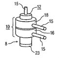
本発明によるWEC8の一例を図1に示す。WECは、水塊内で浮くように、且つ通過波に応じて互いに対して可動であるように設計される第1のフロート10及び第2のフロート12を備える。第1のフロート10は、2つの別個の部材16及び18を備え、これらはそれぞれ、環状の形状であり、中央開口部24を囲む円形のリム20を含む。部材同士は、ストラップ(図示せず)等によって互いに固定され、2つの部材16及び18が1つの環状フロートとして共に機能する。第2のフロート12は、細長い又はスパー状の形状であり、本明細書で示すように1つの部材であるか又は複数の平行な部材(図示せず)を備える。
An example of a
水中に配置されると、WECの向きは図1に示すようになる。すなわち、スパー12が鉛直の向きで浮き、環状フロート10が水面上に水平に浮く。したがって、上述の同時係属中の特許出願に開示されているように、連続した表面波の通過に応じて、2つのフロート10及び12は、互いに位相ずれ関係で浮き沈みする傾向にあり、例えば、一方のフロート、例えば環状フロート10の上昇中はスパーフロート12が下降し得る。
When placed underwater, the orientation of the WEC is as shown in FIG. That is, the spar 12 floats in the vertical direction, and the
2つのフロート10と12との間には、フロート間の相対移動を有用なエネルギーに変換するために、エネルギートランスジューサ、例えば既知のタイプのリニア発電機が配置される。本明細書では示されていないが、リニア発電機を形成する要素は、スパーフロート12の長さ面と、スパーフロート12に直接面する環状フロート10の内面とに沿って配置される。適当なリニア発電機の一例は、2000年2月1日に出願されたWoodbridge他の米国特許第6,020,653号に示されており、当該特許の主題は参照により本明細書に援用される。
Between the two
図1に示すWEC8を構成するフロート部材はそれぞれ、可撓性の非自立型材料から形成される。すなわち、種々のフロート部材は、加圧されていないときは萎んだ風船と同様に潰れる。これにより、システムの輸送及び取り扱いが非常に簡単になる。(図2は、WEC8の種々の部材をまだ膨張させていないときのWEC8を示す。本明細書で後述するような流体をWEC部材に入れるためのホース15も示されている。)
Each of the float members constituting the WEC 8 shown in FIG. 1 is made of a flexible non-self-supporting material. That is, the various float members will collapse like a deflated balloon when not pressurized. This greatly simplifies transportation and handling of the system. (FIG. 2 shows the WEC 8 when the various members of the WEC 8 have not yet been inflated. A
WEC8の種々のフロート材料の可撓性エンベロープは、例えば膨張式タイヤチューブ又は膨張式いかだ等で用いられる種々の市販の材料から成り得る。適当な材料は、ポリ塩化ビニルコーティングゴムチューブ又は「Hypalon」という商標名の合成ゴムである。 The flexible envelope of the various float materials of WEC8 can be made of various commercially available materials used for example in inflatable tire tubes or inflatable rafts. A suitable material is a polyvinyl chloride coated rubber tube or a synthetic rubber under the trade name “Hypalon”.
実用の際には、フロートは、機械力を伝達するために剛性でなければならず、種々のフロート部材は、配置されると完全に膨張する。様々な膨張材料を用いることができるが、好ましい材料は、水及び様々なガス、例えば空気並びに炭酸ガス及び窒素等の市販の加圧ガス等である。したがって、複合環状フロート10の下側の部材16(図1)には水が完全に充填されることが好ましい一方で、上側の部材18には空気が完全に充填される。この図示の実施形態では、2つの部材の体積は等しい。2つの別個の部材16及び18からフロート10を形成する利点は、各部材に他方と無関係に充填を行うことができることである。これにより、配置中のフロート10の重量の微調整が簡単になる。
In practical use, the float must be rigid in order to transmit mechanical force, and the various float members will fully expand when placed. Although various intumescent materials can be used, preferred materials are water and various gases such as air and commercially available pressurized gases such as carbon dioxide and nitrogen. Accordingly, the lower member 16 (FIG. 1) of the composite
二部材型のフロート10とは対照的に、本明細書に示すスパーフロート12は、空気及び水の両方が充填された、例えば体積の80%が水で残りは空気が充填された単一部材である。(図1は、スパー12内の水と空気との間の境界面を示す破線19を含む。)
In contrast to the two-
別の実施形態では、図示はされないが、スパーフロートは、別個の上区画室及び下区画室を備える。上区画室を空気で充填し、下区画室を水99%及び空気1%で充填し、スパーに剛性を付与する。 In another embodiment, not shown, the spar float comprises separate upper and lower compartments. The upper compartment is filled with air and the lower compartment is filled with 99% water and 1% air to impart rigidity to the spar.
スパーを直立の向きで維持するために、例えばコンクリート又は鉛製の錘23が、スパーの下端に配置される。
In order to maintain the spar in an upright orientation, for example, a concrete or
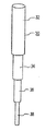
図1及び図2に示す実施形態では、フロート10及び12はいずれも、膨張材料で膨張させられるか又は膨張材料が充填されると拡張する可撓性材料エンベロープを備えるという意味で、袋状である。これとは対照的に、図3は、剛性材料製、例えばステンレス鋼製であるが円筒形セクション32、34、36、及び38が入れ子状に伸縮することによって拡張可能である、スパーフロート30を示す。図4は、畳んだ構成すなわち非拡張構成のスパーフロート30を示す。配置されている間は、種々の入れ子状セクション32、34、36、及び38は、スパーを長さ方向に拡張させるために次々に引き出される。図示はされていないが、スパーセクションを端同士が固定された位置でロックするための既知の手段が設けられることが好ましい。さらに、スパーを拡張構成で維持すると共に鉛直の向きで維持するために、スパーの下端に錘23が配置される。別の実施形態では、水中でもスパーの完全な拡張を確保するために好ましくは圧力下でスパーに1つ又は複数の流体を充填することによって、入れ子状のスパーセクションを拡張させる。
In the embodiment shown in FIGS. 1 and 2, both
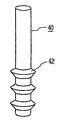
図5には、長さ方向の拡張を可能にするアコーディオンタイプのプリーツ42を有するスパー40が示されている。このような拡張は、充填又は膨張プロセスに応じて、又は単にスパーのプリーツを伸ばすために比較的大きな下部錘23を設けることによって行われ得る。
FIG. 5 shows a
種々のプロセスを用いて、フロートを膨張させることができる。最も単純には、フロートのフロート入口弁44(図1に概略的に示す)を通して水及び/又は空気を圧送することによって、フロートを充填する。図2は、適当な流体(複数可)を内部に圧送するために各フロート部材に連結される別個のホース15を示す。比較的小さなWECの場合、WECが荷船等の上にある間に流体の圧送を行ってから、WECを水中に配置するために持ち上げることができる。
Various processes can be used to inflate the float. Most simply, the float is filled by pumping water and / or air through the float float inlet valve 44 (shown schematically in FIG. 1). FIG. 2 shows a
大きなシステムの場合、WECを未膨張のまま水中に配置した後で、ホースによってフロートに接続された荷船等の上のポンプを用いてWECを膨張させることが概して好ましい。図2は、膨張途中のWEC8を示す。WECの場所は指示されておらず、荷船等の上にあるか、又は水塊にすでに配置されている可能性もある。いずれにしても、WEC部材の拡張は、その内部を流体が満たす結果として行われる。 For large systems, it is generally preferred to inflate the WEC using a pump on a cargo ship or the like connected to the float by a hose after placing the WEC in the unexpanded water. FIG. 2 shows the WEC 8 during expansion. The location of the WEC is not indicated and may be on a cargo ship or already placed in a body of water. In any case, expansion of the WEC member occurs as a result of the fluid filling the interior.
代替的な一構成では、フロートは、フロートを機械的に拡張させるのに用いることができる骨格構造を含む。 In an alternative configuration, the float includes a skeletal structure that can be used to mechanically expand the float.
例えば、図6は、可撓性材料エンベロープ48を構成する環状フロート16を示し、可撓性材料エンベロープ48は、その外周に取り付けられた、タイヤのインナーチューブによく似た外部中空リブ50を含む。流体、例えば空気をリブ50内に圧送して、リブ50を円形に膨張させることにより、取り付けられたフロートエンベロープ48を拡張させる。エンベロープが水塊中に沈んでいる間にエンベロープを拡張させることにより、体積膨張により生じる内圧の低下に応じて水が(入口弁を経て)エンベロープに入る。
For example, FIG. 6 shows an
図6Aは、図1に示す環状フロート16又は18のいずれかを提供するための別の骨格構造61を示す。構造61は、中空スペーサ65によって離間させられた、自転車のインナーチューブと同様の2つの中空チューブ63を備える。スペーサ65は、両方のチューブ63の内側空間と連通している。構造61の全体は、例えばMylar製のエンベロープ(図示せず)内に封入される。使用の際には、構造全体を膨張させるために、1つの弁を通して構造61を空気で膨張させる。
FIG. 6A shows another
図7は、スパーフロート62内に配置された伸縮式骨格構造60を示す。加圧空気又は加圧水を伸縮構造に入れることにより、構造及びフロートの両方の長さ方向の拡張が行われる。このような拡張が行われる場所、すなわち水中か空中かに応じて、拡大された内部空間に周囲の水又は空気が入る。
FIG. 7 shows the telescoping
図8は、環状フロート16内の加圧空気缶66を示す。好ましくは、最初にフロートに水がほぼ完全に充填されることで所望の浮力を提供する。続いて、空気をフロート内に圧送して、所望の内圧及び硬さを提供する。その後、缶66を用いて、失われたであろう空気の代わりを入れる。例えば、激しい暴風雨の状況下及び環状フロートに対する過度に高い外圧下では、1つの安全対策は、内圧を低下させるためにフロートから空気の一部を抜くことである。暴風雨が過ぎると、缶から空気を放出してフロート内の空気圧を正常な作業圧力に戻す。空気缶には他の用法もあり、例えば、フロート部材16の初期膨張、又はフロート18を拡張させるための図6に示すリブ50の膨張を行わせることができる。
FIG. 8 shows a pressurized air can 66 within the
図8は、遠隔制御のために缶66に搭載されたアンテナ80をさらに示す。
FIG. 8 further shows an
Claims (11)
Applications Claiming Priority (2)
| Application Number | Priority Date | Filing Date | Title |
|---|---|---|---|
| US71207105P | 2005-08-29 | 2005-08-29 | |
| PCT/US2006/033689 WO2007027681A2 (en) | 2005-08-29 | 2006-08-28 | Expandable wave energy conversion system |
Publications (2)
| Publication Number | Publication Date |
|---|---|
| JP2009506263A true JP2009506263A (en) | 2009-02-12 |
| JP2009506263A5 JP2009506263A5 (en) | 2012-12-06 |
Family
ID=37809431
Family Applications (1)
| Application Number | Title | Priority Date | Filing Date |
|---|---|---|---|
| JP2008529191A Pending JP2009506263A (en) | 2005-08-29 | 2006-08-28 | Expandable wave energy conversion system |
Country Status (7)
| Country | Link |
|---|---|
| US (1) | US7476137B2 (en) |
| EP (1) | EP1922481B1 (en) |
| JP (1) | JP2009506263A (en) |
| AU (1) | AU2006284946B2 (en) |
| CA (1) | CA2620591A1 (en) |
| PT (1) | PT1922481T (en) |
| WO (1) | WO2007027681A2 (en) |
Cited By (1)
| Publication number | Priority date | Publication date | Assignee | Title |
|---|---|---|---|---|
| JP2014105603A (en) * | 2012-11-26 | 2014-06-09 | Mitsui Eng & Shipbuild Co Ltd | Wave power generator and control method thereof |
Families Citing this family (26)
| Publication number | Priority date | Publication date | Assignee | Title |
|---|---|---|---|---|
| US8067849B2 (en) * | 2005-12-01 | 2011-11-29 | Ocean Power Technologies, Inc. | Wave energy converter with internal mass on spring oscillator |
| AU2007248730B2 (en) * | 2006-05-01 | 2014-02-06 | Ocean Power Technologies, Inc. | Improved wave energy converter (WEC) with heave plates |
| ES2325856B1 (en) * | 2008-03-18 | 2010-06-29 | Manuel Muñoz Saiz | IMPROVEMENTS IN THE ENERGY COLLECTION SYSTEMS OF LAS OLAS DEL MAR. |
| ES2325727B1 (en) * | 2008-03-12 | 2010-06-14 | Manuel Muñoz Saiz | IMPROVEMENTS IN THE ENERGY COLLECTION SYSTEMS OF LAS OLAS DEL MAR. |
| WO2009112598A1 (en) * | 2008-03-12 | 2009-09-17 | Munoz Saiz Manuel | Improvements to systems for harnessing the energy from the waves of the sea |
| US7785163B2 (en) * | 2008-08-15 | 2010-08-31 | Plasti-Fab Inc. | Wave energy buoy |
| US20110057448A1 (en) * | 2009-09-08 | 2011-03-10 | Joseph Page | Wave energy converters |
| GB201103009D0 (en) * | 2011-02-22 | 2011-04-06 | Albatern Ltd | Wave energy absorber |
| JP2013100803A (en) * | 2011-08-09 | 2013-05-23 | Toru Shinohara | Hydraulic power generating apparatus, and hydraulic power generating system |
| US9127640B2 (en) | 2011-09-02 | 2015-09-08 | Rohrer Technologies, Inc. | Multi-capture mode wave energy converter with submergible float |
| US8614520B2 (en) | 2011-11-05 | 2013-12-24 | Rohrer Technologies, Inc. | Submergable sloped absorption barrier wave energy converter |
| US9863395B2 (en) | 2012-05-08 | 2018-01-09 | Rohrer Technologies, Inc. | Wave energy converter with concurrent multi-directional energy absorption |
| US9624900B2 (en) | 2012-10-29 | 2017-04-18 | Energystics, Ltd. | Linear faraday induction generator for the generation of electrical power from ocean wave kinetic energy and arrangements thereof |
| US10011910B2 (en) | 2012-10-29 | 2018-07-03 | Energystics, Ltd. | Linear faraday induction generator for the generation of electrical power from ocean wave kinetic energy and arrangements thereof |
| US8629572B1 (en) | 2012-10-29 | 2014-01-14 | Reed E. Phillips | Linear faraday induction generator for the generation of electrical power from ocean wave kinetic energy and arrangements thereof |
| GB2522695A (en) | 2014-02-03 | 2015-08-05 | Bruce Gregory | Dynamic tuning of wave energy converters using inertial traps |
| USD749369S1 (en) * | 2014-10-22 | 2016-02-16 | James B. Cambridge | Floating beverage holder |
| SE540572C2 (en) * | 2015-03-30 | 2018-10-02 | Olcon Eng Ab | Wave power |
| US10767618B2 (en) * | 2016-04-24 | 2020-09-08 | The Regents Of The University Of California | Submerged wave energy converter for shallow and deep water operations |
| SE540263C2 (en) * | 2016-06-13 | 2018-05-15 | Novige Ab | Apparatus for harvesting energy from waves |
| US9957018B1 (en) * | 2017-02-07 | 2018-05-01 | Cvetan Angeliev | System for wave amplifying, wave energy harnessing, and energy storage |
| US10352290B2 (en) * | 2017-02-14 | 2019-07-16 | The Texas A&M University System | Method and apparatus for wave energy conversion |
| US10578075B2 (en) * | 2017-02-25 | 2020-03-03 | Lone Gull Holdings, Ltd. | Self-propelled buoyant energy converter and method for deploying same |
| US11002243B2 (en) | 2017-04-24 | 2021-05-11 | The Regents Of The University Of California | Submerged wave energy converter for deep water operations |
| US10047717B1 (en) | 2018-02-05 | 2018-08-14 | Energystics, Ltd. | Linear faraday induction generator for the generation of electrical power from ocean wave kinetic energy and arrangements thereof |
| NO346090B1 (en) * | 2019-04-08 | 2022-02-07 | Stationmar As | Single column semi-submersible platform for fixed anchoring in deep water |
Citations (4)
| Publication number | Priority date | Publication date | Assignee | Title |
|---|---|---|---|---|
| JPS5467146A (en) * | 1977-11-05 | 1979-05-30 | Ooshiyan Enerugii Kaihatsu Kk | Method of varying natural synchronous period of up and down oscillation floating body |
| JPS63101190A (en) * | 1986-10-17 | 1988-05-06 | Mitsubishi Heavy Ind Ltd | Float device for refloating sunken matter |
| JP2002138941A (en) * | 2000-11-07 | 2002-05-17 | Yoichi Nishide | Method and device for recovering wave energy |
| US20040163389A1 (en) * | 2003-01-22 | 2004-08-26 | Gerber James S. | Wave energy converter (WEC) device and system |
Family Cites Families (9)
| Publication number | Priority date | Publication date | Assignee | Title |
|---|---|---|---|---|
| US2546956A (en) * | 1944-10-06 | 1951-03-27 | Martha F Watts | Submersible buoy |
| US3570437A (en) * | 1969-02-11 | 1971-03-16 | Texas Instruments Inc | Multi-cycle ocean data gathering system |
| US3991837A (en) * | 1973-05-18 | 1976-11-16 | Joy Manufacturing Company | Buoyant counterbalancing for drill string |
| JP2522175Y2 (en) * | 1990-09-25 | 1997-01-08 | 黒石鉄工株式会社 | Wave oscillation type power generation light emission float |
| CA2146017A1 (en) * | 1992-10-09 | 1994-04-28 | Torger Tveter | A device for a buoy-based wave power apparatus |
| US5842838A (en) * | 1996-11-04 | 1998-12-01 | Berg; John L. | Stable wave motor |
| EP1036274B1 (en) * | 1997-12-03 | 2003-08-27 | William Dick | A wave energy converter |
| KR100416923B1 (en) * | 2001-04-20 | 2004-01-31 | 주식회사 신성기연 | Buoy having self generating device of electricity using power of waves |
| US7199481B2 (en) * | 2003-11-07 | 2007-04-03 | William Walter Hirsch | Wave energy conversion system |
-
2006
- 2006-08-25 US US11/510,459 patent/US7476137B2/en not_active Expired - Fee Related
- 2006-08-28 WO PCT/US2006/033689 patent/WO2007027681A2/en active Application Filing
- 2006-08-28 AU AU2006284946A patent/AU2006284946B2/en not_active Ceased
- 2006-08-28 PT PT68139021T patent/PT1922481T/en unknown
- 2006-08-28 EP EP06813902.1A patent/EP1922481B1/en not_active Expired - Fee Related
- 2006-08-28 CA CA002620591A patent/CA2620591A1/en not_active Abandoned
- 2006-08-28 JP JP2008529191A patent/JP2009506263A/en active Pending
Patent Citations (4)
| Publication number | Priority date | Publication date | Assignee | Title |
|---|---|---|---|---|
| JPS5467146A (en) * | 1977-11-05 | 1979-05-30 | Ooshiyan Enerugii Kaihatsu Kk | Method of varying natural synchronous period of up and down oscillation floating body |
| JPS63101190A (en) * | 1986-10-17 | 1988-05-06 | Mitsubishi Heavy Ind Ltd | Float device for refloating sunken matter |
| JP2002138941A (en) * | 2000-11-07 | 2002-05-17 | Yoichi Nishide | Method and device for recovering wave energy |
| US20040163389A1 (en) * | 2003-01-22 | 2004-08-26 | Gerber James S. | Wave energy converter (WEC) device and system |
Cited By (1)
| Publication number | Priority date | Publication date | Assignee | Title |
|---|---|---|---|---|
| JP2014105603A (en) * | 2012-11-26 | 2014-06-09 | Mitsui Eng & Shipbuild Co Ltd | Wave power generator and control method thereof |
Also Published As
| Publication number | Publication date |
|---|---|
| EP1922481A4 (en) | 2012-12-19 |
| WO2007027681A2 (en) | 2007-03-08 |
| US20070046027A1 (en) | 2007-03-01 |
| CA2620591A1 (en) | 2007-03-08 |
| WO2007027681A3 (en) | 2009-04-16 |
| PT1922481T (en) | 2016-07-12 |
| AU2006284946B2 (en) | 2011-11-24 |
| US7476137B2 (en) | 2009-01-13 |
| EP1922481A2 (en) | 2008-05-21 |
| AU2006284946A1 (en) | 2007-03-08 |
| EP1922481B1 (en) | 2016-04-13 |
Similar Documents
| Publication | Publication Date | Title |
|---|---|---|
| JP2009506263A (en) | Expandable wave energy conversion system | |
| JP2009506263A5 (en) | ||
| US5308191A (en) | Floating barrier method and apparatus | |
| KR20230002043A (en) | Motion absorbing system and method for a structure | |
| AU2015341522B2 (en) | Wave power converter | |
| KR20040037071A (en) | Automatic inflating watercraft flotation device | |
| GB1580805A (en) | Water wave energy conversion device using a flexible walled enclosure | |
| US20050235921A1 (en) | Self-deployable open ocean aquaculture cages and underwater structures | |
| US6801475B2 (en) | Expandable sensor array | |
| US1290979A (en) | Balloon, airship, and other levitating bodies. | |
| GB2120177A (en) | Emergency buoyancy system for semi-submersible vessel | |
| US20190329850A1 (en) | Compartment ballast system | |
| US3475915A (en) | Underwater structures | |
| EP0732963A1 (en) | Inflatable construction | |
| US7128013B1 (en) | Launch tube system having inflatable bladder shock isolation | |
| US20100193053A1 (en) | Methods and systems for pumping fluids | |
| ES2578937T3 (en) | Expandable wave energy conversion system | |
| US2847962A (en) | Salvage apparatus | |
| CN114150814A (en) | Inflatable and expandable rigidizable lunar soil filling brick with foldable rigid shell | |
| US10577062B2 (en) | Self-orienting raft | |
| US20240033581A1 (en) | Fluid Inflatable Member | |
| CN112591145A (en) | Flexible film inflatable cylinder with reinforcing sheath and rectangular parallelepiped containing and folding method thereof | |
| CN214875445U (en) | Support arrangement suitable for experiment in water body | |
| RU156422U1 (en) | FLOATING CARRIER | |
| DK143417B (en) | LIQUID BARRIER TO COLLECT POLLUTANTS IN THE SEA, FLOOD AND SEA AREAS |
Legal Events
| Date | Code | Title | Description |
|---|---|---|---|
| A621 | Written request for application examination |
Free format text: JAPANESE INTERMEDIATE CODE: A621 Effective date: 20090716 |
|
| A977 | Report on retrieval |
Free format text: JAPANESE INTERMEDIATE CODE: A971007 Effective date: 20111026 |
|
| A131 | Notification of reasons for refusal |
Free format text: JAPANESE INTERMEDIATE CODE: A131 Effective date: 20111031 |
|
| A521 | Written amendment |
Free format text: JAPANESE INTERMEDIATE CODE: A523 Effective date: 20120131 |
|
| A131 | Notification of reasons for refusal |
Free format text: JAPANESE INTERMEDIATE CODE: A131 Effective date: 20120711 |
|
| A521 | Written amendment |
Free format text: JAPANESE INTERMEDIATE CODE: A523 Effective date: 20121011 |
|
| A524 | Written submission of copy of amendment under section 19 (pct) |
Free format text: JAPANESE INTERMEDIATE CODE: A524 Effective date: 20121011 |
|
| A02 | Decision of refusal |
Free format text: JAPANESE INTERMEDIATE CODE: A02 Effective date: 20130418 |