JP2009504477A - Device for opening and closing tarpaulins covering the body of industrial, agricultural and similar vehicles - Google Patents
Device for opening and closing tarpaulins covering the body of industrial, agricultural and similar vehicles Download PDFInfo
- Publication number
- JP2009504477A JP2009504477A JP2008525560A JP2008525560A JP2009504477A JP 2009504477 A JP2009504477 A JP 2009504477A JP 2008525560 A JP2008525560 A JP 2008525560A JP 2008525560 A JP2008525560 A JP 2008525560A JP 2009504477 A JP2009504477 A JP 2009504477A
- Authority
- JP
- Japan
- Prior art keywords
- cable
- industrial
- agricultural
- cover device
- section
- Prior art date
- Legal status (The legal status is an assumption and is not a legal conclusion. Google has not performed a legal analysis and makes no representation as to the accuracy of the status listed.)
- Pending
Links
Images


Classifications
-
- B—PERFORMING OPERATIONS; TRANSPORTING
- B60—VEHICLES IN GENERAL
- B60J—WINDOWS, WINDSCREENS, NON-FIXED ROOFS, DOORS, OR SIMILAR DEVICES FOR VEHICLES; REMOVABLE EXTERNAL PROTECTIVE COVERINGS SPECIALLY ADAPTED FOR VEHICLES
- B60J7/00—Non-fixed roofs; Roofs with movable panels, e.g. rotary sunroofs
- B60J7/02—Non-fixed roofs; Roofs with movable panels, e.g. rotary sunroofs of sliding type, e.g. comprising guide shoes
- B60J7/06—Non-fixed roofs; Roofs with movable panels, e.g. rotary sunroofs of sliding type, e.g. comprising guide shoes with non-rigid element or elements
- B60J7/061—Non-fixed roofs; Roofs with movable panels, e.g. rotary sunroofs of sliding type, e.g. comprising guide shoes with non-rigid element or elements sliding and folding
- B60J7/062—Non-fixed roofs; Roofs with movable panels, e.g. rotary sunroofs of sliding type, e.g. comprising guide shoes with non-rigid element or elements sliding and folding for utility vehicles
Landscapes
- Engineering & Computer Science (AREA)
- Mechanical Engineering (AREA)
- Catching Or Destruction (AREA)
- Power-Operated Mechanisms For Wings (AREA)
- Guiding Agricultural Machines (AREA)
- Tents Or Canopies (AREA)
- Building Awnings And Sunshades (AREA)
- Operating, Guiding And Securing Of Roll- Type Closing Members (AREA)
- Agricultural Machines (AREA)
- Body Structure For Vehicles (AREA)
- Pulleys (AREA)
Abstract
Description
本発明は、工業用、農業用及び同様の車両の体部を覆う防水シートの開放及び閉鎖をコントロールするための装置に関し、該装置は、単純で易しい操作によって、車両に適用することが可能な防水シートを開く及び閉じる装置である。 The present invention relates to a device for controlling the opening and closing of a tarpaulin covering the body of industrial, agricultural and similar vehicles, which can be applied to a vehicle by a simple and easy operation. A device for opening and closing a waterproof sheet.
車両の体部を覆うために使用される防水シートは、特に、工業用車両の分野において一般的なものであるが、該防水シートは、移送される物品を保護、維持、及びそれが落下することを防ぐために必要とされている。例えば、砂、砂利又は同様のものを移送する場合、それらは非常に軽く空気の流れの影響を受けやすいので、車両の体部の決められた位置から移動したり、車両が前進することで空気抵抗によって生じた乱流によって分散したりすることがあり、該物品が車両の後方へ落下することがあると、運転上の著しい不都合や、上記移送手段に続いて走行している車両が視界不良になったり、その車両の窓が破損したりするなどして事故をも引き起こす危険がある他、道路の汚れ及び環境汚染といった他の問題も生じる。 The tarpaulin used to cover the body of the vehicle is particularly common in the field of industrial vehicles, but the tarpaulin protects, maintains and drops the goods being transported. It is needed to prevent that. For example, when transferring sand, gravel or the like, they are very light and susceptible to air flow, so they can move from a fixed position on the body of the vehicle or move forward as the vehicle moves forward. May be dispersed by turbulent flow caused by resistance, and if the article falls to the rear of the vehicle, there will be significant inconveniences in driving and the vehicle running following the transfer means will have poor visibility Or the window of the vehicle is damaged, causing other accidents as well as other problems such as road dirt and environmental pollution.
前記目的を達成する、車両用の覆いの分野における既存のタイプの解決策として、該覆いの様々な使用案が存在する。 As an existing type of solution in the field of vehicular covering that achieves the above object, there are various uses of the covering.
前記様々な解決策とは、非常に高価で、及び防水シートで覆われる車両の体部の寸法に従って連続してかなり長時間に渡り長い手順かつ様々な作業を行うことが常に求められる、複雑な手段及び方法を使用することによって前記目的を達成するものである。
例えば、前記様々な解決策は、防水シートを支持する支柱に運動を伝達するためのシャフトを有するシステムからなる複雑なシステムを提供する。また、前記シャフトには、回転することが可能なように他のシャフトが配置されている前記体部の角部に回転運動を伝達するためのベベルギアの組が設けられている。ベベルギアは、全ての部材を動かすために適用される力を減少させることを可能とするために、運動の伝達を低減することが必要とされる。さらに、前記システムは、非常に重く及びかなりの摩擦力を有しているために手動で操作することが容易ではなく、減衰機(Reducer)が設けられていたとしても、電気モータ又は前記目的のために意図された他の代替手段といった補助駆動手段が必要となる。 For example, the various solutions provide a complex system consisting of a system having a shaft for transmitting motion to a column supporting a tarpaulin. Further, the shaft is provided with a set of bevel gears for transmitting rotational motion to the corners of the body part on which another shaft is arranged so as to be able to rotate. The bevel gear is required to reduce the transmission of motion in order to be able to reduce the force applied to move all the members. Furthermore, the system is very heavy and has a considerable frictional force, so it is not easy to operate manually, and even if a reducer is provided, This requires auxiliary drive means such as other alternative means intended.
特許文献1には、ベベルギアの組によって動かされる滑車に沿って走行するケーブルからなる、車両を覆うための防水シートを開く及び閉じるためのシステムが記載されている。この実施形態では、ベベルギアの組が垂直滑車を車両の体部の前側角部に移動させ、及び他の水平前部滑車を通過した後に後側の滑車を移動させるように配置されている伸縮自在の管状要素からなる、工業用、農業用及び同様の車両の体部を覆うための防水シートの開放及び閉鎖をコントロールするための装置によって、上記の問題を部分的に解決している。しかし、その実施形態は、以下の二点において非常に複雑なものとなっている。すなわち、構造的な観点からして、該実施形態は機械化された多くの可動部材を有し、かつそれらの部材は高価である、及び、機能的な観点からして、複数の可動部材にはしばしば検査とコストのかかるメンテナンスを施す必要がある。
さらに、本発明に先行する実施形態は、異なる様々なサイズの体部には適用することができず、よって、異なる様々な使用者に対応するためには、異なるタイプの様々な覆いを製造及び保管することが求められるので付加的な費用がかかる。ベベルギアの組及び滑車を備えたシステムは車両の体部に固定されるので、それには特別に加工された強化構造が前記装置の高さに合わせて該体部に設けられることが必要であり、従って、該装置の連続的な組み立てにおいて、複雑さ及び高コストといった問題が必然的に生じる。 Furthermore, the embodiments preceding the present invention cannot be applied to differently sized body parts, thus producing and covering different types of different coverings to accommodate different different users. Since it is required to be stored, additional costs are incurred. Since the system with a set of bevel gears and a pulley is fixed to the body part of the vehicle, it requires that a specially processed reinforcement structure be provided on the body part to match the height of the device, Therefore, problems such as complexity and high cost inevitably arise in the continuous assembly of the device.
さらに、既存のシステムでは、シートを設置する条件が厳しいので、例えば、覆いが引っかかったり破れたりさえするまで、防水シートの片方の側は他方の側よりも強く引っ張られるために、そのシステムは時折上手く働かず、覆いを取り付ける作業の間に該覆いのケーブルにかかる力が車両の体部の両側に均一に分散することを保証することができない。 In addition, existing systems have harsh conditions for seating, so for example, one side of the tarpaulin is sometimes pulled more strongly than the other until the cover is caught or even torn, so the system occasionally It does not work well and cannot guarantee that the force applied to the cable of the cover during the work of attaching the cover is evenly distributed on both sides of the body of the vehicle.
既存のシステムのケーブル及び稼働部材においては、ベベルギアの組−滑車システムが損傷することを防ぐために頻繁にメンテナンス及びクリーニングを行うことが必要とされ、工場で定期的にメンテナンスするために装置を取り外し、続いて再設置していると時間がかかってしまう。 Existing system cables and moving parts require frequent maintenance and cleaning to prevent damage to the bevel gear set-pulley system, remove equipment for periodic maintenance at the factory, Subsequent re-installation will take time.
従って、本発明は、上記の問題を改善し、工業用、農業用及び同様の車両を覆う防水シートを開く及び閉じるための開放及び閉鎖コントロール装置を提供することを目的としており、該装置は、車両の体部に設置する際における組み立て加工作業といった後の工程を減らすことができ、車両の両側にかかる支持ケーブルの張力を均等に分散させ、往復端部にある支柱を再調整し、ガイド滑車の内部において安全に安定してスライドし、可動部材のメンテナンスがほとんど必要なく、素早く組み立て及び解体を行うことが可能である。 Accordingly, the present invention aims to improve the above problems and to provide an opening and closing control device for opening and closing a tarpaulin covering industrial, agricultural and similar vehicles, Later processes such as assembly work when installing on the body of the vehicle can be reduced, the tension of the support cable on both sides of the vehicle is evenly distributed, the struts at the reciprocating end are readjusted, and the guide pulley Can be safely and stably slid and can be quickly assembled and disassembled with little need for maintenance of the movable member.
前述の要求に応えるシステムは、車両の体部の側板の上端部に沿ってそれぞれの側に配置されたケーブルと、防水シートが固定される支柱と、ケーブルに沿って走行する該防水シートを開く及び閉めるためにそれぞれの側面に設けられた操作装置と、からなり、該操作装置は防水シートが開く及び閉まるようにコントロールするための該装置に設置されていることを特徴とする工業用、農業用及び/又は同様の車両の体部を覆うための装置によって構成されている。 A system that meets the above-described requirements opens a cable disposed on each side along an upper end of a side plate of a vehicle body, a support column to which a waterproof sheet is fixed, and the waterproof sheet that runs along the cable. And an operating device provided on each side for closing, and the operating device is installed in the device for controlling the waterproof sheet so that it opens and closes. And / or a similar device for covering the body of a vehicle.
好ましくは、前記操作装置は、体部の尾板の方に配置されている第1の支柱に設置されている。 Preferably, the operating device is installed on a first support column arranged on the tail plate of the body part.
それは、ギアモータによって作動する駆動滑車と、前記駆動滑車と同一の平面上にある少なくとも2つのダイバーター滑車とから構成されてよく、該駆動滑車は前記ケーブルを把持している。 It may consist of a drive pulley actuated by a gear motor and at least two diverter pulleys on the same plane as the drive pulley, the drive pulley holding the cable.
本発明の好ましい実施形態に従うと、工業用車両の体部を覆うための装置においては、前記駆動滑車の回転軸が複数の前記ダイバーター滑車の軸と平行ではあるが、それらの軸を有する面と同一の平面上にはなく、よって、前記ケーブルは該駆動滑車に沿って走行する間にその軸に従ってずれることとなり、好ましくは、そのずれの角度(α)は10°から120°、好ましくは30°から80°である。 According to a preferred embodiment of the present invention, in an apparatus for covering a body part of an industrial vehicle, the rotational axis of the drive pulley is parallel to the axes of the plurality of diverter pulleys, but the surface having those axes So that the cable will shift along its axis while traveling along the drive pulley, preferably the angle of displacement (α) is 10 ° to 120 °, preferably 30 ° to 80 °.
前記操作装置の駆動滑車は、直径(D)の前記ケーブルが走行する、台形状断面部を備えた案内溝を有しており、小さな基部(g)を有する該台形状断面の角部によって形成される角度(β)は、該ケーブル及び前記駆動滑車が該ケーブルの対称軸から距離(d)だけ移動するように、以下の比率、
g:D:d=0.4〜0.6:1:0.15〜0.2
に従って規定されている。
The drive pulley of the operating device has a guide groove with a trapezoidal cross section where the cable having a diameter (D) travels, and is formed by a corner of the trapezoidal cross section having a small base (g). The angle (β) to be applied is such that the cable and the drive pulley travel a distance (d) from the axis of symmetry of the cable:
g: D: d = 0.4-0.6: 1: 0.15-0.2
It is prescribed according to.
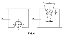
同様に、ダイバーター滑車は、一般的に半円形又は同様の形状の断面を備えた案内溝を有しており、その案内溝の断面の幅は前記ケーブルの断面の直径よりもわずかに大きい。 Similarly, diverter pulleys generally have a guide groove with a semi-circular or similar cross section, the width of the cross section of the guide groove being slightly larger than the diameter of the cross section of the cable.
工業用、農業用及び同様の車両の体部を覆うための前記装置が有する支柱は、半硬化性材料、好ましくは可塑性材料、より好ましくはポリエチレンからなるリブによって互いに結合されており、該リブは、その内部を前記ギアモータに動力を供給するための電気ケーブルが走行しているので、中空であり、好ましくは管状断面を有している。 The struts of the device for covering the body parts of industrial, agricultural and similar vehicles are joined together by ribs made of semi-curing material, preferably plastic material, more preferably polyethylene, Since the electric cable for supplying power to the gear motor runs through the inside, it is hollow and preferably has a tubular cross section.
ケーブルは、スクリューシステムの手段によって、又は体部の前面板に好ましくは配置されたウィンチ手段によって、体部の側板にそって各々引っ張られて設置されており、もし単一のケーブルで、それが体部の側板の後端部から走行している場合、それは、該体部の他方の側板に到達するまで、体部の前面板を通ってU字型に走行する。 The cables are each pulled and installed along the side plate of the body by means of a screw system or by winch means, preferably arranged on the front plate of the body, if a single cable, When traveling from the rear end of the body side plate, it travels U-shaped through the body front plate until it reaches the other side plate of the body part.
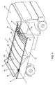
工業用、農業用及び/又は同様の車両の体部を覆うための防水シートの開放及び閉鎖をコントロールするための装置10は、詳細な概略図に示されている工業用車両の体部20に適用されることがこれより記載される。その体部20は、横断支柱21bによって強化された防水シート15によって部分的に覆われている。開放装置11は、第1の横断支柱21bと同じ高さに固定されており、及び体部の両側に配置されている。ギアモータ13からなる開放装置11は、ケーブル17に沿って走行する(図2)。体部の右側及び左側にある各々のケーブル17は、図1に示されているように、体部の側板の前端部と後端部の間にきつく張られるように引っぱられる。ケーブル17をきつく張るために、フックスクリュー牽引システム22が非常に容易な操作でもってケーブル17の端部において使用されることが可能である、又は、1本のケーブルが体部の一方の後端部から始まって、体部の前面壁を通って、体部の他の後端部に到達するまでU字型に走行している。体部の前面壁と同じ高さには、2つのケーブルを同時に引っ張るウィンチ(不図示)が配置されている。これによって、同じ張力でケーブルの2つの長手方向をきつく張ることが可能となる。
An
防水シート15は、実質的に同じものである支柱21a及び21bによって支持されており、該支柱は伸縮自在に調節可能な管状要素からなっていてよい。前記支柱の中央部分は基本的に、適切に曲がることが可能な適切な金属管よりなる区間であるので、結果として支柱(21a−21b)は上方に湾曲した防水シート15のための相対的な支持壁を形成する。前記中央部分を形成する管状区間の両端部においては、該中央部分の内径と等しい外径を有する各々の管状区間が、自由に走行することが可能なように同じやり方でさらに湾曲して挿入されている。これは、支柱21a及び21bの長さが、本発明に係る関連装置が適用される様々な車両体部の有する、異なる様々な幅に適用できるように変化することが可能ということを意味している。最終的な長さは、適切なスクリュー、リベット又は同様のものといった手段によって固定される。
The waterproof sheet 15 is supported by substantially the
また、支柱21a及び21bは単一の管又は同様の区間棒から構成されることも可能である。
The
支柱は柔軟性材料から作られた硬化リブ34によって互いが連結されている。
The struts are connected to each other by a curing
体部の尾板の方に配置されている第1の支柱21°に操作装置11が固定されており、そして該装置は、体部の前端部と後端部の間に渡してあるケーブル17に沿って移動して、該体部を覆うように防水シート15を引っ張ったり、又は反対に、該防水シートを体部の前面壁の方に押すことにより、防水シートによる保護から体部を自由にするために、覆いをはずしたりする。
The
従って、ギアモータ13を備えた開放装置11は防水シートの一部分であり、既存の技術におけるようには体部に固定されてはいない。
Therefore, the
ここでは、体部の側面に固定されたベベルギアの組といった複雑な機械装置や関連する金属加工強化が用いられていない。 Here, complex mechanical devices such as a set of bevel gears fixed to the side of the body part and the associated metal working reinforcement are not used.
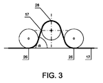
ギアモータ13は中央駆動滑車28に運動を伝達する。すなわち、ケーブル17が、図3により良く示されているように、中央駆動滑車28とケーブル17間の接触面を増加させる機能を有する複数のアイドルダイバーター滑車26の間に配置されており、それによって、前述の2つの構成要素の間の摩擦がケーブル17に沿う作動装置11の運動を十分に保証することができ、従って、適切に防水シート15によって体部を覆うことが可能となる、又は反対に、適切に体部の前面壁へと完全に防水シートを巻き戻すことによって防水シートを開放することが可能となる。
The
開放装置11はケーブル17に沿って走行するので、該装置はケーブル17をクリーンに維持することが可能であり、それによって、ケーブルに汚れが付着することによるトラブルが防止される。
Since the
駆動滑車28の回転軸は、ダイバーター滑車26の軸を含む面と平行ではあるが、それら複数のダイバーター滑車の軸とは同一の平面上にはないので、ケーブル17が駆動滑車28を通過している間、該ケーブルは駆動滑車の軸に従ってずらされている。
The axis of rotation of the
従って、3つの滑車26、28の配置の形態によって、それら滑車の間を走行するケーブル17によって作られる角度α(図3)は決定される。前記角度は、好ましくは10から120°、より好ましくは30から80°の値となるように、設計段階において選択される。
Thus, the configuration of the three
ケーブル17と駆動滑車28の間の摩擦を確実にするために、前記駆動滑車28の案内溝(図4)は小さな基部(g)を備えた台形状断面をなしており、そして、台形状断面において台形側面によって形成された角度βは、直径(D)のケーブル17と駆動滑車28間の接触点が、ケーブル17の対称軸上で案内溝の内部の方に距離(d)だけ移動することが可能なように、下記の比率、
g:D:d=0.4〜0.6:1:0.15〜0.2
に従って選択される。
In order to ensure the friction between the
g: D: d = 0.4-0.6: 1: 0.15-0.2
Selected according to.
同時に、こうすることで、2つの前記構成部材の接触壁部に良好な摩擦をもたらし、比較的に摩耗しにくくすることが可能となる。非限定的な例として、6mmの直径を有するケーブル17では、予想されるずれは、3mmの小さな基部では1mmというオーダーである。
At the same time, this makes it possible to bring good friction to the contact wall portions of the two component members, and to make them relatively difficult to wear. As a non-limiting example, for a
ダイバーター滑車26は可能な限り小さな摩擦でなければならないので、ケーブル17が走行するシート部のスロットは、台形状断面ではなく、一般的に半円状である方がよい。案内溝は、ケーブルが過度に押しつぶされずに案内溝の側壁に対して留まるように、ケーブルの直径と比較してあまり大きくならないようにする必要がある。
Since the
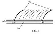
支柱21a及び21bは、半硬化材料、好ましくはポリエチレンからなるリブ34を通して互いが連結されている。それらは構造を頑丈にする機能を有しており、及び、引っ張られることで双方の支柱の間の牽引力を分散させ、一方、押されることで、防水シートを折り畳まれた蛇腹状態という正しい位置に導く(図6)。リブ34は、好ましくは、全体が又は部分的に中空であり、その内部を、ギアモータ13を操作するための電気ケーブルが走行することができる。これによって、電気ケーブルを正しく保護することが可能となる。
The
図1に示されているように、防水シート15は、体部の尾板とも同じ高さにある防水シートを“シーリングする”ことを目的とする端部フラップ36を備えた後方部分まで続いている。操作装置11がスクリューシステム22と同じ高さにある往復端部に到着するとき、端部フラップ36は垂直に上げられ、体部の後方壁に対して配置される。前記のフラップが上がる動きのメカニズムは様々に変更することが可能である。例えば、張力をかけられているチェーンに連結された端部フラップにアームを設けることで、操作装置11が往復端部に到着したときに、体部の後方壁に対して垂直の位置に該端部フラップが上げられる。
As shown in FIG. 1, the tarpaulin 15 continues to the rear portion with end flaps 36 intended to “seal” the tarpaulin at the same height as the tail plate of the body. Yes. When the operating
上述したように、当該装置は、わずかな可動部材よりなる、市場においてすぐに利用可能な非常に簡単な要素から構成されており、それ故に組み立て及び設置が容易であり、工業用、農業用又は他の車両のどのようなタイプの体部にも適用することができることは明らかである。 As mentioned above, the device consists of very simple elements that are readily available in the market, consisting of a few moving parts, and therefore easy to assemble and install, industrial, agricultural or Obviously, it can be applied to any type of body part of other vehicles.
さらに、全ての要素は、設置コストを削減するために“組み立てキット”という形で一般に提供されることが可能なように製造され、よって、慣れていない人でさえも、特別な作業場でのみ利用可能な特別な道具を必要とすることもなく、簡単そして直接的に装置の設置を行うことが可能となる。 In addition, all elements are manufactured so that they can be generally offered in the form of “assembly kits” to reduce installation costs, so even unfamiliar people can only use them in special workplaces The installation of the device can be done easily and directly without the need for special tools that are possible.
本発明は、従来の類似装置と比べて以下のような多くの利点を提供する:
−素早い設置及び解体;
−完全に取り外してメンテナンス工場に送ることにより、体部に既存の技術で固定されている操作装置を含む装置の完全な修理が可能;
−体部上のサイズ制限がない;
−体部にコントロール要素を固定するために特別で面倒な加工作業を行う必要がない;
−牽引金属ケーブルは滑車が通過することで綺麗になる。
The present invention offers a number of advantages over conventional similar devices:
-Quick installation and dismantling;
-Complete repair of the device, including operating devices fixed to the body with existing technology, by removing it completely and sending it to the maintenance shop;
-No size restrictions on the body;
-No need for special and tedious machining operations to secure the control element to the body;
-The tow metal cable is cleaned by the passage of the pulley.
これまで記載され、かつ付属の図面を参照しながら請求されていることの範囲から逸脱しない限り、従って、本工業特許権の保護から逸脱しない限り、本発明の対象をなす装置には異なる様々な変形態が可能である。 There are a variety of different devices that are the subject of the present invention without departing from the scope of what has been described and claimed with reference to the accompanying drawings, and therefore without departing from the protection of this industrial patent right. Variations are possible.
10 防水シートの開放及び閉鎖をコントロールするための装置
11 開放装置
13 ギアモータ
15 防水シート
17 ケーブル
20 体部
21a、21b 支柱
22 フックスクリュー牽引システム
26 ダイバーター滑車
28 駆動滑車
34 リブ
36 端部フラップ
40、42、44 側板
46 尾板
DESCRIPTION OF
Claims (10)
該車両の体部(20)の側板(42、44)の上端部に沿って各々配置されているケーブル(17)と、
防水シート(15)が固定される支柱(21a、21b)と、
該ケーブル(17)に沿って走行している該防水シート(15)を閉じる及び開くために、該体部の各々の側面に設けられた操作装置(11)と、
からなり、該操作装置(11)は該カバー装置(10)に取り付けられていることを特徴とする工業用、農業用及び/又は同様の車両の体部のためのカバー装置(10)。 A cover device (10) for industrial, agricultural and / or similar vehicle body parts,
A cable (17) disposed along the upper end of each side plate (42, 44) of the vehicle body (20);
Struts (21a, 21b) to which the waterproof sheet (15) is fixed;
An operating device (11) provided on each side of the body part for closing and opening the tarpaulin (15) running along the cable (17);
A cover device (10) for an industrial, agricultural and / or similar vehicle body, characterized in that the operating device (11) is attached to the cover device (10).
g:D:d=0.4〜0.6:1:0.15〜0.2
好ましくは、g:D:d=0.5:1:1/6
に従うことを特徴とする請求項3に記載の工業用、農業用及び/又は同様の車両の体部のためのカバー装置(10)。 The drive pulley (28) has a guide groove having a trapezoidal cross section and a small base (g) on which the cable (17) having a diameter (D) travels, and a corner portion of the trapezoidal cross section. The angle (β) formed by is such that the point of contact between the cable (17) and the drive pulley (28) in its cross section is a distance (d) towards its inner side with respect to the axis of symmetry of the cable (17). To move, the following ratio,
g: D: d = 0.4-0.6: 1: 0.15-0.2
Preferably, g: D: d = 0.5: 1: 1/6
4. Cover device (10) for the body part of an industrial, agricultural and / or similar vehicle according to claim 3.
Applications Claiming Priority (2)
| Application Number | Priority Date | Filing Date | Title |
|---|---|---|---|
| EP05107318A EP1754618B1 (en) | 2005-08-09 | 2005-08-09 | Device for controlling opening and closing of tarpaulins for covering the bodies of industrial, agricultural and similar vehicles |
| PCT/EP2006/065093 WO2007017480A1 (en) | 2005-08-09 | 2006-08-04 | Device for opening and closing of tarpaulins for covering the bodies of industrial, agricultural and similar vehicles |
Publications (1)
| Publication Number | Publication Date |
|---|---|
| JP2009504477A true JP2009504477A (en) | 2009-02-05 |
Family
ID=35798306
Family Applications (1)
| Application Number | Title | Priority Date | Filing Date |
|---|---|---|---|
| JP2008525560A Pending JP2009504477A (en) | 2005-08-09 | 2006-08-04 | Device for opening and closing tarpaulins covering the body of industrial, agricultural and similar vehicles |
Country Status (15)
| Country | Link |
|---|---|
| US (1) | US7887117B2 (en) |
| EP (1) | EP1754618B1 (en) |
| JP (1) | JP2009504477A (en) |
| CN (1) | CN101238004B (en) |
| AT (1) | ATE391039T1 (en) |
| AU (1) | AU2006277927B2 (en) |
| CA (1) | CA2614848C (en) |
| DE (1) | DE602005005813T2 (en) |
| DK (1) | DK1754618T3 (en) |
| ES (1) | ES2306018T3 (en) |
| PL (1) | PL1754618T3 (en) |
| PT (1) | PT1754618E (en) |
| RU (1) | RU2415763C2 (en) |
| SM (1) | SMP200700054B (en) |
| WO (1) | WO2007017480A1 (en) |
Families Citing this family (16)
| Publication number | Priority date | Publication date | Assignee | Title |
|---|---|---|---|---|
| ES2306018T3 (en) * | 2005-08-09 | 2008-11-01 | Trakover Srl | DEVICE FOR THE CONTROL OF THE OPENING AND CLOSURE OF TOLDOS TO COVER BODIES OF INDUSTRIAL, AGRICULTURAL AND SIMILAR VEHICLES. |
| CA2673199C (en) * | 2006-12-20 | 2014-10-07 | Trakover S.R.L. | Control device for opening and closing open top bodies in industrial vehicles |
| ATE535411T1 (en) * | 2009-03-25 | 2011-12-15 | Marcolin S R L | DRIVE DEVICE FOR TRUCK COVERS |
| WO2011019377A2 (en) * | 2009-08-10 | 2011-02-17 | Unifrax I Llc | Variable basis weight mounting mat or pre-form and exhaust gas treatment device |
| US8572901B2 (en) * | 2011-01-21 | 2013-11-05 | Thomas A. Holstrom | Compost cover tie-down system |
| CN103358973B (en) * | 2012-04-06 | 2016-02-17 | 北京精诚博桑科技有限公司 | A kind of carried automobile tarpaulin covering device |
| US8820717B2 (en) * | 2012-10-26 | 2014-09-02 | Tin Inc. | System and method for placing a tarpaulin over a load |
| US8864212B2 (en) * | 2013-01-30 | 2014-10-21 | Cramaro Tarpaulin Systems, Inc. | Drive units for tarpaulin cover systems |
| US20140271093A1 (en) * | 2013-03-14 | 2014-09-18 | Poet Research, Inc. | Self-strapping round bale trailer |
| EP2977248A1 (en) | 2014-07-23 | 2016-01-27 | Marcolin Covering Srl | Covering system for open top-bodies |
| ITUB20154958A1 (en) | 2015-11-03 | 2017-05-03 | Trakover S R L | Drive and towing device for box cover system on fixed guides |
| US9862256B2 (en) | 2016-03-11 | 2018-01-09 | Cramaro Tarpaulin Systems | Guide unit for tarpaulin cover system |
| DE202016101823U1 (en) * | 2016-04-06 | 2016-05-23 | European Trailer Systems Gmbh | tarpaulin |
| US20180312099A1 (en) * | 2017-04-26 | 2018-11-01 | Ford Global Technologies, Llc | Hybrid tonneau cover/work surface for vehicle |
| KR20200107995A (en) * | 2019-03-05 | 2020-09-16 | 주식회사 선광코리아 | Automatic opening/closing device for cargo vehicle loading box cover |
| CN110203126B (en) * | 2019-06-13 | 2021-08-24 | 梁山陆畅通专用车制造有限公司 | Goods covering device for freight transport vehicle |
Citations (3)
| Publication number | Priority date | Publication date | Assignee | Title |
|---|---|---|---|---|
| EP0181730A2 (en) * | 1984-10-31 | 1986-05-21 | O'Brien, Stephen | Stowable cover |
| JP2000301950A (en) * | 1999-04-22 | 2000-10-31 | Daikure Co Ltd | Device for automatically opening and closing awning |
| JP2003002188A (en) * | 2001-06-19 | 2003-01-08 | Shuichiro Shimomura | Shifter |
Family Cites Families (29)
| Publication number | Priority date | Publication date | Assignee | Title |
|---|---|---|---|---|
| US3201171A (en) * | 1964-02-19 | 1965-08-17 | Re Trac To Inc | Retractable truck body cover with tension control |
| US3688787A (en) * | 1970-04-29 | 1972-09-05 | Clark B Feather | Longitudinally collapsible canopy for pickup trucks and analagous frames |
| US3820840A (en) * | 1973-08-01 | 1974-06-28 | J Forsberg | Truck body cover |
| US4162100A (en) * | 1977-04-07 | 1979-07-24 | Pasquale Muscillo | Cover assembly for open boxes of vehicles |
| US4289346A (en) * | 1978-12-18 | 1981-09-15 | Bourgeois Norman J | Collapsible protective cover mechanism |
| US4210361A (en) * | 1979-02-28 | 1980-07-01 | Lohman Edmond L | Sliding cover assembly for open body trucks |
| US4285539A (en) * | 1979-03-09 | 1981-08-25 | Cole Richard C | Retractable tonneau top |
| US4547014A (en) * | 1984-01-16 | 1985-10-15 | Wicker James A | Articulated rigid cover assembly for truck beds |
| US4756325A (en) * | 1985-11-01 | 1988-07-12 | Daniels Duane D | Collapsible canopy for pick-up trucks |
| US5145230A (en) * | 1987-07-23 | 1992-09-08 | Vito Biancale | Tarpaulin cover |
| FR2654685A1 (en) * | 1989-11-22 | 1991-05-24 | Libner Joseph | TRANSPORT VEHICLE COVERED BY RACING. |
| DE9012980U1 (en) * | 1990-09-12 | 1990-12-06 | Ed. Scharwächter GmbH + Co. Fahrzeugtechnik, 8355 Hengersberg | Retractable roof, especially for trucks and trailers |
| US5338084A (en) * | 1992-12-16 | 1994-08-16 | Roll-A-Cover Inc. | Cover system for flatbed trailers and kit therefor |
| US5427428A (en) * | 1993-10-04 | 1995-06-27 | Ericson; John C. | Folding cover for the bed of a pickup truck |
| US5429408A (en) * | 1993-12-06 | 1995-07-04 | Aero Industries, Inc. | Waterproof retractable tarp cover system for containers |
| US5524953A (en) * | 1994-06-03 | 1996-06-11 | Shaer; Jack E. | Contractable vehicle bed cover assembly with extendable closure |
| WO1996033882A1 (en) * | 1995-04-26 | 1996-10-31 | Denyer David K | Retractable tarpaulin cover apparatus for open-topped containers such as truck bodies |
| US5938270A (en) * | 1997-08-26 | 1999-08-17 | Shur Company | Quick release bow-to-cable connector for a covering system |
| WO1999012759A1 (en) * | 1997-09-08 | 1999-03-18 | Tadao Shinohara | Cargo carrying vehicle |
| DE19839775A1 (en) * | 1998-09-01 | 2000-03-02 | Edscha Lkw Schiebeverdeck Gmbh | Foldable tarpaulin structure for vehicle bodies and containers |
| US6142554A (en) * | 1999-03-18 | 2000-11-07 | Truckhugger Tarp Systems, Inc. | Sliding bow dump truck cover |
| US6676189B2 (en) * | 2001-01-29 | 2004-01-13 | Webasto Sunroofs, Inc. | Cover assembly for a vehicle bed |
| ITPN20010008A1 (en) | 2001-01-31 | 2002-07-31 | Bortolin Regina Di Pivetta Ivo | DEVICE FOR THE CONTROL IN OPENING AND CLOSING OF CANVAS COVERING THE BOXES OF INDUSTRIAL, AGRICULTURAL AND / OR SIMILAR VEHICLES |
| CN2570100Y (en) * | 2002-08-19 | 2003-09-03 | 姜忠扬 | Closed box cover of folding freight car |
| US6948760B2 (en) * | 2003-05-28 | 2005-09-27 | Webasto Sunroofs, Inc. | Cover assembly for a vehicle bed and method for mounting the same |
| ITBA20030057A1 (en) * | 2003-11-07 | 2005-05-08 | Ambrogio Lippolis | CABRIOLET TYPE COVER FOR INDUSTRIAL VEHICLES. |
| DE202004018433U1 (en) | 2004-11-28 | 2005-03-24 | Kaltenhauser Max | Covering for a dumping truck tipping to three sides has a tarpaulin firmly linked to hoops over the body of the dumping truck |
| US7140665B2 (en) * | 2005-02-25 | 2006-11-28 | Q-Sales & Leasing Llc | Temperature protection system for cargo trailers |
| ES2306018T3 (en) * | 2005-08-09 | 2008-11-01 | Trakover Srl | DEVICE FOR THE CONTROL OF THE OPENING AND CLOSURE OF TOLDOS TO COVER BODIES OF INDUSTRIAL, AGRICULTURAL AND SIMILAR VEHICLES. |
-
2005
- 2005-08-09 ES ES05107318T patent/ES2306018T3/en active Active
- 2005-08-09 DK DK05107318T patent/DK1754618T3/en active
- 2005-08-09 EP EP05107318A patent/EP1754618B1/en active Active
- 2005-08-09 DE DE602005005813T patent/DE602005005813T2/en active Active
- 2005-08-09 PT PT05107318T patent/PT1754618E/en unknown
- 2005-08-09 PL PL05107318T patent/PL1754618T3/en unknown
- 2005-08-09 AT AT05107318T patent/ATE391039T1/en active
-
2006
- 2006-08-04 CN CN2006800289867A patent/CN101238004B/en not_active Expired - Fee Related
- 2006-08-04 US US12/063,187 patent/US7887117B2/en not_active Expired - Fee Related
- 2006-08-04 WO PCT/EP2006/065093 patent/WO2007017480A1/en active Application Filing
- 2006-08-04 JP JP2008525560A patent/JP2009504477A/en active Pending
- 2006-08-04 CA CA2614848A patent/CA2614848C/en not_active Expired - Fee Related
- 2006-08-04 RU RU2008101691/11A patent/RU2415763C2/en not_active IP Right Cessation
- 2006-08-04 SM SM200700054T patent/SMP200700054B/en unknown
- 2006-08-04 AU AU2006277927A patent/AU2006277927B2/en not_active Ceased
Patent Citations (3)
| Publication number | Priority date | Publication date | Assignee | Title |
|---|---|---|---|---|
| EP0181730A2 (en) * | 1984-10-31 | 1986-05-21 | O'Brien, Stephen | Stowable cover |
| JP2000301950A (en) * | 1999-04-22 | 2000-10-31 | Daikure Co Ltd | Device for automatically opening and closing awning |
| JP2003002188A (en) * | 2001-06-19 | 2003-01-08 | Shuichiro Shimomura | Shifter |
Also Published As
| Publication number | Publication date |
|---|---|
| RU2008101691A (en) | 2009-09-20 |
| CN101238004B (en) | 2010-05-19 |
| AU2006277927A1 (en) | 2007-02-15 |
| CN101238004A (en) | 2008-08-06 |
| ATE391039T1 (en) | 2008-04-15 |
| DE602005005813D1 (en) | 2008-05-15 |
| EP1754618B1 (en) | 2008-04-02 |
| PL1754618T3 (en) | 2008-10-31 |
| CA2614848A1 (en) | 2007-02-15 |
| EP1754618A1 (en) | 2007-02-21 |
| US20090322116A1 (en) | 2009-12-31 |
| US7887117B2 (en) | 2011-02-15 |
| WO2007017480A1 (en) | 2007-02-15 |
| DE602005005813T2 (en) | 2009-04-16 |
| SMAP200700054A (en) | 2007-11-28 |
| SMP200700054B (en) | 2007-11-28 |
| RU2415763C2 (en) | 2011-04-10 |
| AU2006277927B2 (en) | 2012-05-10 |
| CA2614848C (en) | 2014-10-07 |
| ES2306018T3 (en) | 2008-11-01 |
| DK1754618T3 (en) | 2008-07-28 |
| PT1754618E (en) | 2008-07-14 |
Similar Documents
| Publication | Publication Date | Title |
|---|---|---|
| JP2009504477A (en) | Device for opening and closing tarpaulins covering the body of industrial, agricultural and similar vehicles | |
| US8220860B2 (en) | Control device for opening and closing open top bodies in industrial vehicles | |
| ITTV20060133A1 (en) | OPERATING A COVERING SHEET. | |
| EP1738946B1 (en) | Control device for opening and closing open top bodies in industrial vehicles | |
| WO2011077316A1 (en) | Control device for opening and closing open top bodies in industrial vehicles | |
| JP4555579B2 (en) | Vehicle bite latch | |
| EP1228912B1 (en) | Control device for opening and closing open top bodies in industrial vehicles | |
| JP2019172043A (en) | Sunshade device and crane truck | |
| EP3165387B1 (en) | Actuating and towing device for a cover system on secured guides for a truck-body | |
| JP2008307928A (en) | Cargo tight binding device | |
| RU2373076C2 (en) | Device to open and close vehicle open body | |
| KR102226278B1 (en) | The apparatus for carrying of automatic for dump cover | |
| KR101830261B1 (en) | apparatus for opening and closing a scattering dust cover for freight car | |
| KR960010045Y1 (en) | Device for rotating of camera head of remote control car for inspection pipe inside | |
| JP2004138090A (en) | Chain type transfer device | |
| JPH08127247A (en) | Push and pull drive device using open end roller chain, and opening and closing device for expandable awning of truck using it | |
| JPH055033B2 (en) | ||
| JPS5811699A (en) | Shifter for hose | |
| ITAP20100004A1 (en) | LOW CROSS SECTION SUSPENSION FOR TRAILERS WITH RELATIVE SYSTEM TO LOWER AND RAISE THE LOADING PLAN | |
| KR20030050441A (en) | Automatic cart | |
| ITBS20060109A1 (en) | TENSIONER FOR SELF-TRANSPORT VEHICLE SHEETS | |
| JP2007270425A (en) | Sliding door opening and closing device and its assembly method | |
| JPH11269830A (en) | Traffic regulator |
Legal Events
| Date | Code | Title | Description |
|---|---|---|---|
| A621 | Written request for application examination |
Free format text: JAPANESE INTERMEDIATE CODE: A621 Effective date: 20090804 |
|
| A977 | Report on retrieval |
Free format text: JAPANESE INTERMEDIATE CODE: A971007 Effective date: 20110922 |
|
| A131 | Notification of reasons for refusal |
Free format text: JAPANESE INTERMEDIATE CODE: A131 Effective date: 20111108 |
|
| A02 | Decision of refusal |
Free format text: JAPANESE INTERMEDIATE CODE: A02 Effective date: 20120410 |