JP2009298220A - System and method for detecting electric leak - Google Patents
System and method for detecting electric leak Download PDFInfo
- Publication number
- JP2009298220A JP2009298220A JP2008152864A JP2008152864A JP2009298220A JP 2009298220 A JP2009298220 A JP 2009298220A JP 2008152864 A JP2008152864 A JP 2008152864A JP 2008152864 A JP2008152864 A JP 2008152864A JP 2009298220 A JP2009298220 A JP 2009298220A
- Authority
- JP
- Japan
- Prior art keywords
- ecu
- electronic control
- leakage detection
- control unit
- compressor
- Prior art date
- Legal status (The legal status is an assumption and is not a legal conclusion. Google has not performed a legal analysis and makes no representation as to the accuracy of the status listed.)
- Pending
Links
Images


Abstract
Description
本発明は、漏電検出システム及び方法に関するものであり、特に、自動車エアコン用電動コンプレッサにおける漏電検出システムに使用されるのに好適である。 The present invention relates to a leakage detection system and method, and is particularly suitable for use in a leakage detection system in an electric compressor for an automobile air conditioner.
ハイブリッド車や燃料電池車等では、特許文献1に示すように、制御機能を分割して複数のECUに割り付けるようにしたものが知られている。このような車両において、ECU間におけるデータや情報の転送、交換は、一般的には、CAN(Controller Area Network)やLIN(Local Interconnect Network)といったシリアル通信を使って行われている。 As shown in Patent Document 1, a hybrid vehicle, a fuel cell vehicle, or the like is known in which a control function is divided and assigned to a plurality of ECUs. In such a vehicle, transfer and exchange of data and information between ECUs is generally performed using serial communication such as CAN (Controller Area Network) or LIN (Local Interconnect Network).
ハイブリッド車は、駆動力を発生するための走行用駆動源として、電力により駆動される電気モータである車両駆動用モータと、ガソリンなどを燃料とする内燃機関である車両駆動用エンジンとを備えている。車両駆動用エンジンを制御するECU(Electronic Control Unit)や、高電圧バッテリを操作するECUや、高電圧を使ってモータ等のアクチュエータを制御するECU等により、発進時および低速走行時には車両用モータからの駆動力のみにより走行し、通常走行時にはエンジン又は車両用モータのいずれかの駆動力により走行する。車両の空調装置は、ハイブリッド車の車室内を空調するためのエアコンユニットと、エアコンユニットを構成するエアコンECU等から成り、この空調装置は車室内の温度を設定温度に保つように制御している。 The hybrid vehicle includes a vehicle drive motor that is an electric motor driven by electric power, and a vehicle drive engine that is an internal combustion engine using gasoline or the like as a driving source for driving to generate driving force. Yes. From a vehicle motor during start-up and low-speed running, such as an ECU (Electronic Control Unit) that controls a vehicle drive engine, an ECU that operates a high-voltage battery, or an ECU that controls an actuator such as a motor using a high voltage The vehicle travels only with the driving force of the engine, and travels with the driving force of either the engine or the vehicle motor during normal traveling. The vehicle air conditioner includes an air conditioner unit for air conditioning the interior of the hybrid vehicle and an air conditioner ECU that constitutes the air conditioner unit. The air conditioner controls the temperature of the interior of the vehicle to be maintained at a set temperature. .
このようなハイブリッド車では、走行用モータ駆動用の電池の電圧が200V以上の高電圧バッテリを使っている事例が多く、部品交換や点検等のメンテナンス時において 誤って感電しない方策を確立することが重要となってきている。このような方策の一例として、ボンネットを開けると、開いたことを検知するスイッチを設けたものが、実用化されている。このスイッチにより、高電圧バッテリを制御する高電圧制御ECUが、高電圧バッテリからの車両内への電力供給を遮断する。 In such hybrid vehicles, there are many cases where high-voltage batteries with a driving motor driving battery voltage of 200 V or higher are used, and it is possible to establish measures to prevent electric shocks during maintenance such as component replacement and inspection. It has become important. As an example of such a measure, a switch provided with a switch for detecting that the bonnet is opened when the hood is opened has been put into practical use. By this switch, the high voltage control ECU that controls the high voltage battery cuts off the power supply from the high voltage battery into the vehicle.
さらに、感電防止をレベルアップさせるためには、前記のメカニカルなスイッチによる遮断だけでなく 高電圧を扱う複数のECUを利用した別の遮断手段が要望されてきている。しかしながら、ECU間通信を利用した遮断システムでは、ECU間通信に異常があってECU間相互に確実な制御連携ができないと、漏電検出や電力遮断制御において誤検出や誤作動の恐れが生じてしまう。 Furthermore, in order to improve the level of electric shock prevention, there has been a demand for other shut-off means using a plurality of ECUs that handle not only the mechanical switch but also a high voltage. However, in an interruption system using communication between ECUs, if there is an abnormality in communication between ECUs and reliable control coordination between ECUs is not possible, there is a risk of erroneous detection or malfunction in leakage detection or power interruption control. .
特に、コンプレッサ制御ECUの場合は、通信ネットワーク制御 ECUのような上位ECUから「漏電検出モードに移行」しろという指令を受け取ると、INV−ECUを漏電検出モードに移行させる。上位ECUとコンプレッサECUとは車内ネットワークを介して接続されているため、コンプレッサECUが受け取る信号は常に正しいとは限らない。ノイズなどの外乱により上位ECUから「漏電検出モードに移行」という信号を受けていないにも関わらず、INV−ECUを漏電検出モードに移行すると、INV−ECUはコンプレッサを駆動できなくなり、車室内の空調を継続できなくなる。 In particular, in the case of a compressor control ECU, upon receiving a command to “shift to leakage detection mode” from a host ECU such as a communication network control ECU, the INV-ECU is shifted to a leakage detection mode. Since the host ECU and the compressor ECU are connected via the in-vehicle network, the signal received by the compressor ECU is not always correct. If the INV-ECU shifts to the leakage detection mode even though it does not receive a signal “transition to the leakage detection mode” from the host ECU due to disturbances such as noise, the INV-ECU cannot drive the compressor, Air conditioning cannot be continued.
さらに、CAN等の通信ネットワークの異常を確認せずに実行すると、複数のECUが相互に連携して行う漏電故障検出では相手のECUの作動状況を把握しないまま、100Vを超える高電圧操作や故障検出を行う恐れがあり、正しい漏電検出ができなくなるといった問題が発生する。 Furthermore, if it is executed without confirming an abnormality in a communication network such as CAN, a high-voltage operation or failure exceeding 100 V is detected without detecting the operation status of the counterpart ECU in the detection of leakage faults performed by a plurality of ECUs in cooperation with each other. There is a risk of detection, which causes a problem that correct leakage detection cannot be performed.
本発明の解決しようとする課題は、上記問題に鑑み、ECU間通信を利用した漏電検出システムにおいて、上位のECUから漏電検出指令が届いたときに、ECUに故障が存在する場合や、ECU間通信に異常があって、ECU間相互に確実な制御連携ができない場合による漏電検出の誤検出や誤作動を防止できる漏電検出システムを提供することである。 In view of the above problems, the problem to be solved by the present invention is that in a leakage detection system using communication between ECUs, when a leakage detection command arrives from a host ECU, a failure exists in the ECU, It is an object of the present invention to provide a leakage detection system capable of preventing erroneous detection and malfunction of leakage detection when there is an abnormality in communication and reliable control coordination between ECUs is not possible.
本発明は、上記課題を達成するために、以下の技術的手段を採用する。
請求項1に記載の発明では、高電圧バッテリを制御する電子制御ユニット(ECU)、電動コンプレッサを制御するコンプレッサ制御電子制御ユニット(ECU)、及び、通信ネットワークを制御する電子制御ユニット(ECU)を含む複数の電子制御ユニット(ECU)、並びに、
該複数の電子制御ユニット(ECU)間で情報の授受を行う通信ネットワーク
を具備する漏電検出システムにおいて、
漏電検出操作を実行する前に、前記コンプレッサ制御電子制御ユニット(ECU)に故障が存在しておらず、かつ、前記コンプレッサ制御電子制御ユニット(ECU)が、
前記電子制御ユニット(ECU)間の前記通信ネットワークによる通信が正常に行われたという条件が成立したことを確認した場合に、漏電検出操作を実行する。
これにより、ECUに故障が存在する場合や、ECU間通信に異常があって、ECU間相互に確実な制御連携ができない場合による、漏電検出の誤検出や誤作動を防止でき、確実な漏電検出、及び、漏電検査の実行が行うことができる。
The present invention employs the following technical means in order to achieve the above-mentioned problems.
According to the first aspect of the present invention, an electronic control unit (ECU) that controls a high-voltage battery, a compressor control electronic control unit (ECU) that controls an electric compressor, and an electronic control unit (ECU) that controls a communication network are provided. Including a plurality of electronic control units (ECUs), and
In the electric leakage detection system comprising a communication network for exchanging information between the plurality of electronic control units (ECUs),
Before performing the leakage detection operation, there is no failure in the compressor control electronic control unit (ECU), and the compressor control electronic control unit (ECU)
When it is confirmed that the condition that the communication by the communication network between the electronic control units (ECUs) has been normally performed is satisfied, the leakage detection operation is executed.
As a result, it is possible to prevent erroneous detection or malfunction of leakage detection when there is a failure in the ECU, or when there is an abnormality in communication between ECUs and mutual control coordination between ECUs is not possible, and reliable leakage detection And the execution of a leakage check can be performed.
請求項2に記載の発明では、請求項1の発明において、前記複数の電子制御ユニット(ECU)に、さらに、高電圧を使いアクチュエータを制御する電子制御ユニット(ECU)を含むことを特徴とする。
これにより、請求項1に記載の発明と同様に、確実な漏電検出、及び、漏電検査の実行が行える。
According to a second aspect of the present invention, in the first aspect of the invention, the plurality of electronic control units (ECUs) further includes an electronic control unit (ECU) that controls an actuator using a high voltage. .
Thereby, similarly to the invention according to claim 1, it is possible to perform reliable leakage detection and execution of leakage inspection.
請求項3に記載の発明では、請求項1の発明において、前記コンプレッサ制御電子制御ユニット(ECU)が、ハイブリッド自動車、燃料電池車、又は、電気自動車におけるエアコン用電動コンプレッサを制御する電子制御ユニット(ECU)であることを特徴とする。
これにより、請求項1に記載の発明と同様に、電動コンプレッサ - 高電圧バッテリ系のシステムにおける確実な漏電検出、及び、漏電検査の実行を行うことができる。
According to a third aspect of the present invention, in the first aspect of the invention, the compressor control electronic control unit (ECU) controls an electric compressor for an air conditioner in a hybrid vehicle, a fuel cell vehicle, or an electric vehicle. ECU).
Thus, similarly to the first aspect of the invention, it is possible to perform reliable leakage detection and leakage check in the electric compressor-high voltage battery system.
請求項4に記載の発明では、請求項1の発明において、前記コンプレッサ制御電子制御ユニット(ECU)は、第1種の通信プロトコルと第2種の通信プロトコルとで情報交換するためのゲートウエイ電子制御ユニット(GW−ECU3)と、インバータモータを制御する電子制御ユニット(INV−ECU4)を具備することを特徴とする。
これにより、請求項1に記載の発明と同様に、電気的な絶縁を図るために、フォトカプラを搭載した INV−ECU4とは別に高速なCANバスと情報交換を行う為 ゲートウエイ機能を持たせたECU(GW−ECU3)を備えた構成の場合にも、確実な漏電検出、及び、漏電検査の実行が行える。
According to a fourth aspect of the present invention, in the first aspect of the invention, the compressor control electronic control unit (ECU) is a gateway electronic control for exchanging information between the first type communication protocol and the second type communication protocol. A unit (GW-ECU3) and an electronic control unit (INV-ECU4) for controlling the inverter motor are provided.
Thus, in the same manner as in the first aspect of the invention, a gateway function is provided in order to exchange information with a high-speed CAN bus separately from the INV-ECU 4 equipped with a photocoupler in order to achieve electrical insulation. Even in the case of a configuration including the ECU (GW-ECU 3), it is possible to perform reliable leakage detection and leakage inspection.
請求項5に記載の発明では、請求項1の発明において、前記通信ネットワークが、車載用として規定している通信プロトコル(CAN、LIN、FLEX−RAY、MOST、その他のシリアル通信)を使用していることを特徴とする。これにより、漏電検出専用の通信回線を用意することなく、もともとECU間の通信で使用していた通信ネットワークを活用することができ、高電圧の漏電検出を行うシステムを車両用に適用することが容易である。 According to a fifth aspect of the present invention, in the first aspect of the invention, the communication network uses a communication protocol (CAN, LIN, FLEX-RAY, MOST, or other serial communication) specified for in-vehicle use. It is characterized by being. This makes it possible to utilize a communication network originally used for communication between ECUs without preparing a dedicated communication line for detecting leakage, and to apply a system for detecting high-voltage leakage to vehicles. Easy.
請求項6に記載の発明では、請求項1の発明において、前記複数の電子制御ユニット(ECU)は、さらに、強制的に電源をカットするための時限タイマ(ステップS118)を具備することを特徴とする。これにより、突然、通信ネットワークの故障が生じて、情報のやり取りができなくなった場合でも、自力で電源をカットして、ECUに電力供給するバッテリの消耗を防ぐことができる。 According to a sixth aspect of the present invention, in the first aspect of the invention, the plurality of electronic control units (ECUs) further include a timed timer (step S118) for forcibly cutting off the power. And As a result, even when the communication network suddenly fails and information cannot be exchanged, the power supply can be cut by itself to prevent the battery supplying the ECU from being consumed.
請求項7に記載の発明は、高電圧バッテリを制御する電子制御ユニット(ECU)、電動コンプレッサを制御するコンプレッサ制御電子制御ユニット(ECU)、及び、通信ネットワークを制御する電子制御ユニット(ECU)を含む複数の電子制御ユニット(ECU)間で、前記通信ネットワークにより情報の授受を行うステップと、漏電検出操作を実行する前に、前記コンプレッサ制御電子制御ユニット(ECU)に故障が存在しておらず、かつ、前記コンプレッサ制御電子制御ユニット(ECU)が、前記電子制御ユニット(ECU)間の前記通信ネットワークによる通信が正常に行われたという条件が成立したことを確認するステップ(S200〜S203)と、前記確認するステップで、前記条件が成立した場合、漏電検出操作を実行するステップ(S115)を具備する漏電検出方法に関する。
これにより、ECUに故障が存在する場合や、ECU間通信に異常があって、ECU間相互に確実な制御連携ができない場合による、漏電検出の誤検出や誤作動を防止でき、確実な漏電検出、及び、漏電検査の実行が行うことができる。
The invention described in claim 7 includes an electronic control unit (ECU) that controls a high-voltage battery, a compressor control electronic control unit (ECU) that controls an electric compressor, and an electronic control unit (ECU) that controls a communication network. There is no failure in the compressor control electronic control unit (ECU) before performing the step of exchanging information through the communication network between the plurality of electronic control units (ECU) including the leakage detection operation. And the compressor control electronic control unit (ECU) confirming that the condition that the communication by the communication network between the electronic control units (ECU) is normally performed is established (S200 to S203); In the step of checking, if the condition is satisfied, About leakage detection method comprising the step (S115) to the line.
As a result, it is possible to prevent erroneous detection or malfunction of leakage detection when there is a failure in the ECU, or when there is an abnormality in communication between ECUs and mutual control coordination between ECUs is not possible, and reliable leakage detection And the execution of a leakage check can be performed.
なお、上記に付した符号は、後述する実施形態に記載の具体的実施態様との対応関係を示す一例である。 In addition, the code | symbol attached | subjected above is an example which shows a corresponding relationship with the specific embodiment as described in embodiment mentioned later.
以下、図面を参照して、本発明の一実施形態を説明する。
図1は、エアコン用電動コンプレッサシステムを示す全体概略図である。図2は、図1の一部詳細概略図である。
エアコン用電動コンプレッサ1は、気化した冷媒を圧縮して液化する冷媒コンプレッサ6と、コンプレッサを駆動するインバータモータ5と、冷媒コンプレッサに繋がれ冷媒が配送される冷媒配管8と、これらを電子制御する2つのECU 、すなわち、インバータ制御ECU4(以下、INV−ECU4と略す。)と、ゲートウエイECU3(以下、GW−ECU3と略す。)からなる。INV−ECU4とGW−ECU3とはコンプレッサ制御ECUを構成する。
Hereinafter, an embodiment of the present invention will be described with reference to the drawings.
FIG. 1 is an overall schematic diagram showing an electric compressor system for an air conditioner. FIG. 2 is a partial detailed schematic view of FIG.
The electric compressor 1 for an air conditioner electronically controls a refrigerant compressor 6 that compresses and liquefies the vaporized refrigerant, an inverter motor 5 that drives the compressor, a refrigerant pipe 8 that is connected to the refrigerant compressor and delivers refrigerant. It consists of two ECUs, that is, an inverter control ECU 4 (hereinafter abbreviated as INV-ECU 4) and a gateway ECU 3 (hereinafter abbreviated as GW-ECU 3). The INV-ECU 4 and the GW-ECU 3 constitute a compressor control ECU.
INV−ECU4は、ハイブリッド車用高電圧バッテリ7から高電圧(一例では288V)12を受けて GW−ECU3からの制御情報に従い、インバータモータ5を駆動する 。GW−ECU3は、エアコンECU16からのインバータモータの回転数の情報をCANバス13経由で受けて、INV−ECU4に、SCI通信17経由で伝達する。感電防止の視点から、GW−ECU3とINV−ECU4との間は、フォトカプラを使って電気的な絶縁を図っている。このため、通信速度を、CAN通信の水準に上げられないので、電動コンプレッサ1におけるSCI通信17を、車両ネットワークであるCANバス13に接続する為に、GW−ECU3をおいて情報交換を行っている。
The INV-ECU 4 receives the high voltage (for example, 288V) 12 from the high-voltage battery 7 for the hybrid vehicle, and drives the inverter motor 5 according to the control information from the GW-ECU 3. The GW-ECU 3 receives information on the rotational speed of the inverter motor from the air conditioner ECU 16 via the CAN
高電圧制御ECU2は、主に、ハイブリッド車用高電圧バッテリ7から電源を送出するか否かのON/OFFを、スイッチング信号10にて行うことにより、図示しないハイブリッド車駆動用のモータや、本システムのインバータモータ5への高電圧供給の制御を行っている。このECUには詳細には説明しないが、漏電検出センサ9が接続されており、高電圧出力時の漏電の有無を検知できるようになっている。
The high voltage control ECU 2 mainly performs ON / OFF of whether or not to send power from the high voltage battery 7 for the hybrid vehicle by the
ネットワークマネジメントECU15は、本システムでは、後述のIG−Keyの状態(スタートボタンのONかOFFの状態を指す。)やスリープモードへの遷移等を、CANバス13に接続された各ECUに通知したりする。
In this system, the
図3は、GW−ECUにおける処理の全体的フローチャートを示す。
GW−ECUに電源が入ると、パワーオンリセット状態(ステップS100) となり、所定の初期設定処理(ステップS101)が実行される。ここでは、後述の漏電検出フラグを0にクリアしておく。パワーオンリセット状態とは、GW−ECUを始めとする各ECUが、電源が入るとマイコンがリセット状態から復帰し、プログラムを実行可能な状態となったことを意味する。
FIG. 3 shows an overall flowchart of processing in the GW-ECU.
When the power is turned on to the GW-ECU, a power-on reset state (step S100) is entered, and a predetermined initial setting process (step S101) is executed. Here, a leak detection flag described later is cleared to zero. The power-on reset state means that each ECU including the GW-ECU has returned to the microcomputer from the reset state when the power is turned on, and the program is ready to be executed.
ステップ102において、予めスケジューリングされた時間同期プログラムにより、2ms処理(ステップS103) 、10ms処理(ステップS104)、100ms処理(ステップS105)等の各タスク処理が実行される。これらの時間同期処理はGW−ECU3の電源がOFFされるまで継続的に実行される。 In step 102, each task process such as a 2 ms process (step S103), a 10 ms process (step S104), and a 100 ms process (step S105) is executed by a time synchronization program scheduled in advance. These time synchronization processes are continuously executed until the power of the GW-ECU 3 is turned off.
図4は、GW−ECUにおける漏電検出のフローチャートを示す。この処理は、図2における10ms処理の中のタスクとしてプログラムされている。
運転ドライバがIG−Key(スタートボタン)を押すと、ネットワークマネジメントECUがこれを認識し、各ECUに対してウェイクアップパルスを、専用回線を通じて発行し、各ECUに強制的に電源が入る仕組みになっている。GW−ECU3が起動されると同時に、CANバス経由でIG−Key情報(IG−Key ON)が送られる。GW−ECU3は、IG−Key状態を認識する。スタートボタンが押されてONになっている状態が、IG−Key ONであり、再度押されてOFFになると、IG−Key OFFの状態となる。
FIG. 4 shows a flowchart of leakage detection in the GW-ECU. This process is programmed as a task in the 10 ms process in FIG.
When the driving driver presses the IG-Key (start button), the network management ECU recognizes this, issues a wake-up pulse to each ECU through a dedicated line, and forces the power to each ECU. It has become. At the same time that the GW-ECU 3 is activated, IG-Key information (IG-Key ON) is sent via the CAN bus. The GW-ECU 3 recognizes the IG-Key state. The state where the start button is pressed and turned ON is IG-Key ON, and when the button is pressed again and turned OFF, the state is IG-Key OFF.
ネットワークマネジメントECU15から、CANバス13経由で送られるIG−Key OFF情報が、ONからOFFに変化したか否かをステップS110で確認し、IG−KeyがONからOFFに変わった場合、漏電検出フラグを1にセットする(ステップ112)。ONからOFFに変わった場合の検知手段としては、10ms前の過去情報を保持しておき、最新の情報と比較することで検知することができる。
In step S110, it is confirmed whether or not the IG-Key OFF information sent from the
なお、ステップS112でセットした漏電検出フラグは、後述のステップS115で、GW−ECU3からINV−ECU4に対して、漏電検出用としてIGBT(絶縁ゲート型バイポーラトランジスタ)を駆動操作するために、SCI通信で送出される。他方、漏電検出フラグが1である場合の漏電検出作動モードになっていることを明示することで、ダイアグノーシス(車両自己診断機能)等の他の処理において、誤作動や誤検出しないためにも使用される。 Note that the leakage detection flag set in step S112 is used for SCI communication in order to drive the IGBT (insulated gate bipolar transistor) for leakage detection from the GW-ECU 3 to the INV-ECU 4 in step S115 described later. Sent out. On the other hand, by clearly indicating that the earth leakage detection operation mode is set when the earth leakage detection flag is 1, in other processes such as diagnosis (vehicle self-diagnosis function), it is possible to prevent malfunction or detection. used.
IG−KeyがONからOFFに変わった場合以外(NOの場合)は、ステップS111で、IG−Key情報の状態をチェックする。このとき、OFFでない(IG−Key ON)ならば、その後、運転ドライバがIG−KeyをOFFにして、車両を停止させる行為を検出するまでは、この漏電検出ロジックは機能させず、ステップS119を経て本処理を抜ける。 OFFであれば、ステップS113に移行する。これは、OFFの場合は、既に漏電検出フラグが1にセットされており、ステップS112が不要だからである。 Except when the IG-Key is changed from ON to OFF (in the case of NO), the state of the IG-Key information is checked in Step S111. At this time, if it is not OFF (IG-Key ON), the leakage detection logic does not function until the driver detects that the driver turns OFF the IG-Key and stops the vehicle, and step S119 is performed. After that, this process is exited. If it is OFF, the process proceeds to step S113. This is because when it is OFF, the leakage detection flag is already set to 1, and step S112 is unnecessary.
次に、漏電検出作動モードを確認 (ステップS113) する。ここでは運転ドライバが IG−KeyをOFFしたものの、システムとして本当に漏電検出し可能な状態にあるかを確認するために設けられている。確認の条件は、図5の説明の部分で詳細を説明する。 Next, the leakage detection operation mode is confirmed (step S113). Here, it is provided to confirm whether the system driver is actually in a state where it can detect leakage even though the driving driver has turned off IG-Key. Details of the confirmation conditions will be described in the description of FIG.
ステップS113において漏電検出条件が不成立と判断した時は、後述のステップ117のスリープモードへの移行判断の確認に移る。
ステップ113で漏電検出可と判断された場合は、INV−ECU4に対して、漏電検出用のIGBT駆動操作をSCI通信で指示(ステップS115)する。
When it is determined in step S113 that the leakage detection condition is not satisfied, the process proceeds to confirmation of the determination to shift to the sleep mode in step 117 described later.
If it is determined in
次いで、高電圧制御ECU2に対して漏電検出検査フラグ情報を発信し、漏電検出検査の実行許可を通知する。(ステップS116)
すなわち、漏電検出検査フラグが0から1に変化すると、高電圧制御ECU2のタイミング処理ループで、1が立つことで、漏電検出検査の実行許可がなされ、高電圧制御ECU2では、漏電検出センサ9を用い漏電検出を行う。
Next, leakage detection inspection flag information is transmitted to the high-voltage control ECU 2 to notify permission to execute the leakage detection inspection. (Step S116)
That is, when the leakage detection inspection flag changes from 0 to 1, the execution of the leakage detection inspection is permitted by setting 1 in the timing processing loop of the high voltage control ECU 2, and the high voltage control ECU 2 sets the
ステップS117では スリープアクト(スリープモードへの移行可否をチェックする処理)を行う。このスリープアクト情報は、ネットワークマネジメントECU15が 各ECUに対して、IG−Key情報を発信後、所定時間(一例では20分)待って、発信し、スリープモードに各ECUを遷移させる情報である。スリープアクト情報が来た時、スリープモードへの移行ができると判断する。
In step S117, a sleep act (a process for checking whether or not to enter the sleep mode) is performed. This sleep act information is information that causes the
ステップS117で、GW−ECU3が、スリープモードへ移行可能ならば、漏電検出フラグを0にクリア(ステップS119)して処理を終了する。スリープモードへ移行可能でない場合は、強制的に電源をカットする時間が経過(一例では31分)したかを確認(ステップS118)して、時間を経過していない場合は、そのまま何もせずに処理を終了する。時間を経過した場合は、漏電検出フラグを0にクリア(ステップ119)して処理を終了する。この強制電源カット時間を監視する目的は、CANバス13等に異常があった時、ネットワークマネジメントECU15からスリープアクト情報が来なくなり、GW−ECU3の電源が、いつまでも切れずにバッテリを消耗するのを回避するためである。
If the GW-ECU 3 can shift to the sleep mode in step S117, the leakage detection flag is cleared to 0 (step S119), and the process ends. If it is not possible to shift to the sleep mode, it is confirmed whether the time for forcibly turning off the power (for example, 31 minutes) has elapsed (step S118). If the time has not elapsed, nothing is done as it is. The process ends. If the time has elapsed, the leakage detection flag is cleared to 0 (step 119), and the process ends. The purpose of monitoring the forced power cut-off time is that when there is an abnormality in the
この漏電検出システムは、ネットワークマネジメントECU15のIG−Key OFFを起点に、GW−ECUで漏電検出判断と、INV−ECU4に対する漏電検出用のIGBT駆動操作を行い、高電圧制御ECU2は、漏電検出センサ9を使って漏電検出の有無を実行する。
This earth leakage detection system starts from the IG-Key OFF of the
漏電検出検査フラグ情報は、GW−ECU3で、INV−ECU4に対して漏電検出用IGBT駆動操作を行った時点で、高電圧制御ECU2に対して発行される。高電圧制御ECU2は、漏電検出検査フラグ情報を受信後、漏電検出センサ9を使用して電動コンプレッサ1での漏電検出検査を3秒間行い、もし、漏電が確認された場合は、高電圧バッテリ7に対して電力供給を停止し、INV−ECU4の主電源を直ちにカットする。
The leakage detection inspection flag information is issued to the high voltage control ECU 2 when the GW-ECU 3 performs the leakage detection IGBT drive operation on the INV-ECU 4. After receiving the leakage detection detection flag information, the high voltage control ECU 2 performs a leakage detection inspection in the electric compressor 1 using the
ネットワークマネジメントECU15は IG−Key OFF情報を発信後、高電圧制御ECU2での漏電検出検査のため5秒間待つが、その検査結果、又は、検査実施の有無の如何を問わず、各ECUに対して、スリープアクト情報をCANバス13上に出し、スリープモードに遷移させる。GW−ECU3は、スリープモードへの遷移要求の情報により内蔵の電源回路をカットする。
The
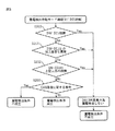
図5は、図4の「漏電検出作動モードの確認」の詳細内容を示している。
ここでは、INV−ECU4の故障の有無(ステップS200)、INV−ECU4とのSCI通信異常の有無(ステップS201)、GW−ECU3に記録された他の故障検出の有無(ステップS202)、CAN通信異常の検出の有無(ステップS203)により、漏電検出条件が不成立か、成立か、または、INV−ECU4等異常のため、漏電検出しないかを識別している。
FIG. 5 shows the detailed contents of “Confirmation of leakage detection operation mode” in FIG.
Here, the presence / absence of failure of the INV-ECU 4 (step S200), the presence / absence of SCI communication abnormality with the INV-ECU 4 (step S201), the presence / absence of other failure detection recorded in the GW-ECU 3 (step S202), CAN communication The presence / absence of abnormality detection (step S203) identifies whether the leakage detection condition is not established, established, or whether leakage detection is not performed due to an abnormality such as INV-ECU4.
図5のステップS200、S201、S202、S203の異常・故障の基本的な定義について、次に説明する。 Next, the basic definition of abnormality / failure in steps S200, S201, S202, and S203 in FIG. 5 will be described.
1.INV−ECU4の故障の定義
INV−ECU4自身が、そのドライビングサイクル(IG−Key Onの期間)中にIGBT等の回路素子の過熱状態やインバータモータ5の作動不良、その他、ECU内部で発生した異常を検出した時。(この異常はGW−ECU3に通知される。)
1. Definition of failure of the INV-ECU 4 The INV-ECU 4 itself is in an overheated state of circuit elements such as IGBTs, malfunctions of the inverter motor 5 during the driving cycle (IG-Key On period), and other abnormalities that occur inside the ECU. When it is detected. (This abnormality is notified to the GW-ECU 3)
2.GW−ECU3とINV−ECU4との間のSCI通信で起こる通信データの異常の定義
(1)通信回線の断線 又は、短絡、ECUの電源変動による作動不良、CPU暴走等が発生し、定期通信の送受信イベントが、2つのECUの少なくともいずれかで発生しなくなったことを検出した時。
(2)GW−ECU3、INV−ECU4が、SCI通信時にパリティやフレーミングエラー、オーバーランエラーのいずれかをUART(Universal Synchronous Asynchronous Receiver Transmitter)モジュールで検出される通信エラーを認識した時。GW−ECU3、INV−ECU4がSCI通信時にその他の手段により通信エラーを認識した時。
2. Definition of communication data abnormality that occurs in SCI communication between GW-ECU 3 and INV-ECU 4 (1) Disconnection or short circuit of communication line, malfunction due to ECU power fluctuation, CPU runaway, etc. When it is detected that a transmission / reception event no longer occurs in at least one of the two ECUs.
(2) When the GW-ECU 3 and the INV-ECU 4 recognize a communication error detected by a UART (Universal Synchronous Asynchronous Receiver Transmitter) module at the time of SCI communication, any of a parity, a framing error, and an overrun error. When the GW-ECU 3 and the INV-ECU 4 recognize a communication error by other means during SCI communication.
3.GW−ECU3の故障の定義
GW−ECU3自身が、そのドライビングサイクル(IG−Key Onの期間)中にECU内部で発生した異常を検出した時。
3. Definition of failure of the GW-ECU 3 When the GW-ECU 3 itself detects an abnormality occurring in the ECU during the driving cycle (IG-Key On period).
4.CANバス13上で起こる通信データの異常の定義
(1)CANバスオフエラー発生時。
(2)高電圧制御ECU2から高電圧情報が、定期的に送られなくなったことを示す故障が検出された時。
これは、高電圧情報がCAN通信で送られてこなくなったことを意味し、本事例では一例として、高電圧情報は、高電圧制御ECU2から100ms毎に送られてきている。
(3)ネットワークマネジメントECU15から、IG−Key情報が送られていないことを検出した時。これは、GW−ECU3が、パワーオンリセット後、一度もIG−Key情報(ONであれ、OFFであれ)を受け取っていないと認識した時を指している。
(4)エアコンECU16から、インバータモータ5の制御回転数情報が、定期的に送られなくなったことを示す故障が検出された時。
(5)CANバス上の各ECUが、CANバス上での通信時に何らかの故障を検出したことを示すエラー情報を配信した時。
4). Definition of communication data error on CAN bus 13 (1) When a CAN bus off error occurs.
(2) When a failure indicating that high voltage information is no longer sent periodically from the high voltage control ECU 2 is detected.
This means that high voltage information is no longer sent by CAN communication. In this example, as an example, high voltage information is sent from the high voltage control ECU 2 every 100 ms.
(3) When it is detected from the
(4) When a failure indicating that the control rotational speed information of the inverter motor 5 is not sent periodically is detected from the
(5) When each ECU on the CAN bus distributes error information indicating that some failure has been detected during communication on the CAN bus.
以上の実施態様においては、CANバスを用いて説明しているが、LIN、FLEX−RAY、MOST、他のシリアル通信などの通信プロトコルのよる各ECU間の通信においても、すべての車載用として規定している通信プロトコルならいずれにおいても、これまで述べてきた漏電検出システムは適用可能である。 In the above embodiment, the CAN bus is used for the description. However, the communication between ECUs using communication protocols such as LIN, FLEX-RAY, MOST, and other serial communication is specified for all in-vehicle use. The leakage detection system described so far can be applied to any communication protocol.
1 エアコン用電動コンプレッサ
3 ゲートウエイECU(GW−ECU)
4 インバータ制御ECU(INV−ECU)
5 インバータモータ
6 冷凍コンプレッサ
7 ハイブリッド車用高電圧バッテリ
8 冷凍配管
9 漏電検出センサ
10 スイッチング信号
12 288V高電圧出力
13 CANバス
15 ネットワークマネジメントECU
16 エアコンECU
1 Electric compressor for air conditioner 3 Gateway ECU (GW-ECU)
4 Inverter control ECU (INV-ECU)
DESCRIPTION OF SYMBOLS 5 Inverter motor 6 Refrigeration compressor 7 High voltage battery for hybrid vehicles 8
16 Air conditioner ECU
Claims (7)
該複数の電子制御ユニット(ECU)間で情報の授受を行う通信ネットワーク
を具備する漏電検出システムにおいて、
漏電検出操作を実行する前に、前記コンプレッサ制御電子制御ユニット(ECU)に故障が存在しておらず、かつ、前記コンプレッサ制御電子制御ユニット(ECU)が、
前記電子制御ユニット(ECU)間の前記通信ネットワークによる通信が正常に行われたという条件が成立したことを確認した場合に、漏電検出操作を実行する漏電検出システム。 A plurality of electronic control units (ECU) including an electronic control unit (ECU) for controlling the high voltage battery, a compressor control electronic control unit (ECU) for controlling the electric compressor, and an electronic control unit (ECU) for controlling the communication network As well as
In the electric leakage detection system comprising a communication network for exchanging information between the plurality of electronic control units (ECUs),
Before performing the leakage detection operation, there is no failure in the compressor control electronic control unit (ECU), and the compressor control electronic control unit (ECU)
An earth leakage detection system for executing an earth leakage detection operation when it is confirmed that a condition that communication by the communication network between the electronic control units (ECUs) has been normally performed is satisfied.
漏電検出操作を実行する前に、前記コンプレッサ制御電子制御ユニット(ECU)に故障が存在しておらず、かつ、前記コンプレッサ制御電子制御ユニット(ECU)が、前記電子制御ユニット(ECU)間の前記通信ネットワークによる通信が正常に行われたという条件が成立したことを確認するステップと、
前記確認するステップで、前記条件が成立した場合、漏電検出操作を実行するステップを具備する漏電検出方法。 A plurality of electronic control units (ECU) including an electronic control unit (ECU) for controlling the high voltage battery, a compressor control electronic control unit (ECU) for controlling the electric compressor, and an electronic control unit (ECU) for controlling the communication network Sending and receiving information via the communication network,
Before executing the leakage detection operation, there is no failure in the compressor control electronic control unit (ECU), and the compressor control electronic control unit (ECU) is connected between the electronic control units (ECU). A step of confirming that a condition that the communication via the communication network has been normally performed is satisfied;
A leakage detection method comprising a step of executing a leakage detection operation when the condition is satisfied in the checking step.
Priority Applications (1)
| Application Number | Priority Date | Filing Date | Title |
|---|---|---|---|
| JP2008152864A JP2009298220A (en) | 2008-06-11 | 2008-06-11 | System and method for detecting electric leak |
Applications Claiming Priority (1)
| Application Number | Priority Date | Filing Date | Title |
|---|---|---|---|
| JP2008152864A JP2009298220A (en) | 2008-06-11 | 2008-06-11 | System and method for detecting electric leak |
Publications (1)
| Publication Number | Publication Date |
|---|---|
| JP2009298220A true JP2009298220A (en) | 2009-12-24 |
Family
ID=41545585
Family Applications (1)
| Application Number | Title | Priority Date | Filing Date |
|---|---|---|---|
| JP2008152864A Pending JP2009298220A (en) | 2008-06-11 | 2008-06-11 | System and method for detecting electric leak |
Country Status (1)
| Country | Link |
|---|---|
| JP (1) | JP2009298220A (en) |
Cited By (3)
| Publication number | Priority date | Publication date | Assignee | Title |
|---|---|---|---|---|
| JP2016525975A (en) * | 2013-05-24 | 2016-09-01 | マーレ インターナショナル ゲゼルシャフト ミット ベシュレンクテル ハフツングMAHLE International GmbH | Electrical system assembly for automobiles |
| CN106240493A (en) * | 2016-07-21 | 2016-12-21 | 安徽师范大学 | Electric automobile wire-controlled apparatus based on CAN |
| CN111999676A (en) * | 2020-09-03 | 2020-11-27 | 国家电网有限公司 | Electric leakage fault remote alarm system for transformer substation |
Citations (5)
| Publication number | Priority date | Publication date | Assignee | Title |
|---|---|---|---|---|
| JP2004336907A (en) * | 2003-05-08 | 2004-11-25 | Denso Corp | Inverter system |
| JP2006087293A (en) * | 2004-09-10 | 2006-03-30 | Ford Global Technologies Llc | Predicting method and system for component of hybrid electric vehicle |
| JP2006233917A (en) * | 2005-02-25 | 2006-09-07 | Denso Corp | Starter control device |
| JP2007253683A (en) * | 2006-03-22 | 2007-10-04 | Fujitsu Ten Ltd | Control device |
| JP2007303374A (en) * | 2006-05-11 | 2007-11-22 | Toyota Motor Corp | Vehicle engine starting system |
-
2008
- 2008-06-11 JP JP2008152864A patent/JP2009298220A/en active Pending
Patent Citations (5)
| Publication number | Priority date | Publication date | Assignee | Title |
|---|---|---|---|---|
| JP2004336907A (en) * | 2003-05-08 | 2004-11-25 | Denso Corp | Inverter system |
| JP2006087293A (en) * | 2004-09-10 | 2006-03-30 | Ford Global Technologies Llc | Predicting method and system for component of hybrid electric vehicle |
| JP2006233917A (en) * | 2005-02-25 | 2006-09-07 | Denso Corp | Starter control device |
| JP2007253683A (en) * | 2006-03-22 | 2007-10-04 | Fujitsu Ten Ltd | Control device |
| JP2007303374A (en) * | 2006-05-11 | 2007-11-22 | Toyota Motor Corp | Vehicle engine starting system |
Cited By (3)
| Publication number | Priority date | Publication date | Assignee | Title |
|---|---|---|---|---|
| JP2016525975A (en) * | 2013-05-24 | 2016-09-01 | マーレ インターナショナル ゲゼルシャフト ミット ベシュレンクテル ハフツングMAHLE International GmbH | Electrical system assembly for automobiles |
| CN106240493A (en) * | 2016-07-21 | 2016-12-21 | 安徽师范大学 | Electric automobile wire-controlled apparatus based on CAN |
| CN111999676A (en) * | 2020-09-03 | 2020-11-27 | 国家电网有限公司 | Electric leakage fault remote alarm system for transformer substation |
Similar Documents
| Publication | Publication Date | Title |
|---|---|---|
| US10243760B2 (en) | Communication device, communication method, and communication system | |
| US6678586B2 (en) | Vehicle built-in electronic control apparatus | |
| CN102929272B (en) | A kind of motor system fault processing method and processor | |
| US10911252B2 (en) | Communication system for vehicle and method for controlling the same | |
| US7446428B2 (en) | Method of diagnosing main relay by use of electronic control unit and electronic control unit | |
| US9251632B2 (en) | Vehicle diagnostic system | |
| US7518261B2 (en) | Method of diagnosing main relay by use of electronic control unit and electronic control unit | |
| JP2005100029A (en) | Onboard electronic control device | |
| JP6258997B2 (en) | Vehicle control system | |
| CN105298709A (en) | Engine starting control system and control method | |
| JP2007046546A (en) | Controller for idle stop vehicle | |
| WO2015194407A1 (en) | Vehicle-mounted control device or vehicle-mounted control system | |
| US20170003179A1 (en) | Fault diagnosis system and method of exhaust gas temperature sensor of hybrid vehicle | |
| JP2012086591A (en) | Series hybrid vehicle control system | |
| CN105242608A (en) | Vehicle control unit and control method thereof | |
| JP4003062B2 (en) | Communication error detection method in bus communication network | |
| CN108547694B (en) | Detection method, detection device and detection system of electromagnetic fan | |
| JP2009298220A (en) | System and method for detecting electric leak | |
| WO2011000250A1 (en) | Method for detecting can bus of hybrid motor vehicle | |
| CN113371057B (en) | Motor control device | |
| WO2011034052A1 (en) | Vehicle electronic control device | |
| JP2011093389A (en) | Control system, electronic devices, control device, and method for starting devices | |
| CN111757829B (en) | Control apparatus and method for controlling operation of internal combustion engine and motor in hybrid vehicle | |
| JP6819193B2 (en) | Vehicle charging system | |
| CN112406466B (en) | Equipment fault processing device and method and air conditioner |
Legal Events
| Date | Code | Title | Description |
|---|---|---|---|
| A621 | Written request for application examination |
Free format text: JAPANESE INTERMEDIATE CODE: A621 Effective date: 20100623 |
|
| A977 | Report on retrieval |
Free format text: JAPANESE INTERMEDIATE CODE: A971007 Effective date: 20120427 |
|
| A131 | Notification of reasons for refusal |
Free format text: JAPANESE INTERMEDIATE CODE: A131 Effective date: 20120508 |
|
| A02 | Decision of refusal |
Free format text: JAPANESE INTERMEDIATE CODE: A02 Effective date: 20121002 |