JP2009297377A - Suction port body for vacuum cleaner, and vacuum cleaner - Google Patents
Suction port body for vacuum cleaner, and vacuum cleaner Download PDFInfo
- Publication number
- JP2009297377A JP2009297377A JP2008157532A JP2008157532A JP2009297377A JP 2009297377 A JP2009297377 A JP 2009297377A JP 2008157532 A JP2008157532 A JP 2008157532A JP 2008157532 A JP2008157532 A JP 2008157532A JP 2009297377 A JP2009297377 A JP 2009297377A
- Authority
- JP
- Japan
- Prior art keywords
- vacuum cleaner
- rotary cleaning
- mouthpiece
- cleaning body
- side end
- Prior art date
- Legal status (The legal status is an assumption and is not a legal conclusion. Google has not performed a legal analysis and makes no representation as to the accuracy of the status listed.)
- Pending
Links
Images


Abstract
Description
本発明は、駆動源で回転駆動する回転清掃体を備えた電気掃除機用吸口体、及びその電気掃除機用吸口体を備える電気掃除機に関するものである。 The present invention relates to a suction mouthpiece for a vacuum cleaner provided with a rotary cleaning body that is rotationally driven by a drive source, and a vacuum cleaner provided with the suction body for the vacuum cleaner.
電気掃除機用吸口体は、掃除機の吸気風を利用して回転清掃体自身が回転力を発生するものや、モータ等の回転力で回転清掃体を駆動するものがある。 The suction body for an electric vacuum cleaner includes a rotary cleaning body that generates a rotational force by using the intake air of the vacuum cleaner, and a rotary cleaner that drives the rotary cleaning body by a rotational force of a motor or the like.
駆動用モータ等の回転力を回転清掃体へ伝えるもののうち、二つの噛合い部A、Bを用い回転清掃体の着脱が容易にできる使い勝手を向上させたものがある〔実開昭51−27477号公報(特許文献1)、特許第3249188号公報(特許文献2)〕。 Among those that transmit the rotational force of the drive motor or the like to the rotary cleaning body, there is one that uses two meshing portions A and B to improve the ease of use with which the rotary cleaning body can be easily attached and detached [Japanese Utility Model Publication No. 51-27477. (Patent Document 1), Japanese Patent No. 3249188 (Patent Document 2)].
この電気掃除機用吸口体において、回転清掃体の端部の片側(駆動側端部)は噛合い部A、Bの合せによって把持され、回転清掃体のもう一方の端部(非駆動側端部)は軸受台を含む回転支持部材に支持され、回転支持部材は上ケース及び、下ケースから構成される吸口体本体と、その下部に配置される軸受カバーAによって把持される。 In this vacuum cleaner mouthpiece, one side (driving side end) of the end of the rotary cleaning body is gripped by the mating portions A and B, and the other end (non-driving side end) of the rotary cleaning body. Part) is supported by a rotation support member including a bearing base, and the rotation support member is gripped by a suction body main body composed of an upper case and a lower case, and a bearing cover A disposed below the suction body.
これにより、回転清掃体を取り外す際は、軸受カバーを取り外すだけで、容易に取り外すことが可能となっている。 Thereby, when removing a rotary cleaning body, it can remove easily only by removing a bearing cover.
このような噛合い部を用いた電気掃除機用吸口体では、回転清掃体へ動力を伝達するための噛合い部及び、プーリを含む動力伝達機構が配置されている。 In the suction body for an electric vacuum cleaner using such a meshing portion, a meshing portion for transmitting power to the rotary cleaning body and a power transmission mechanism including a pulley are arranged.
上記の背景技術では、回転清掃体の両端部が対称形状又は、似た形状の場合、回転清掃体の取り付け時に、使用者が回転清掃体の向きを容易に判断できず、吸口体への組み込みの向きを間違え易いため、使い勝手を損ねる。 In the above background art, when both ends of the rotary cleaning body are symmetrical or similar in shape, the user cannot easily determine the orientation of the rotary cleaning body when the rotary cleaning body is attached, and is incorporated into the mouthpiece. Because it is easy to make a mistake in the orientation, it is difficult to use.
本発明は、上記の課題に鑑み、回転清掃体の両端部が対称形状、又は似た形状であっても、使用者が回転清掃体のメンナンスに際し、噛合い部A、Bの噛み合わせや、回転支持部材の所定位置への取り付けが目視で誤りなく容易に行うことができる使い勝手の良い電気掃除機用吸口体、および電気掃除機を提供することを目的とする。 In the present invention, in view of the above-described problems, even if both ends of the rotary cleaning body are symmetrical or similar, the user can engage the meshing portions A and B when performing maintenance of the rotary cleaning body, An object of the present invention is to provide an easy-to-use vacuum cleaner mouthpiece and a vacuum cleaner in which the rotation support member can be easily attached to a predetermined position visually without error.
本発明は、吸口体本体に設けられ、そこに備えた回転清掃体を回転駆動する駆動源と、前記駆動源の回転を前記回転清掃体に伝達する動力伝達機構を備え、前記動力伝達機構は、前記回転清掃体の駆動側端部に設ける噛合い部Aと、前記噛合い部Aと脱着自在に連結し、かつ噛合い部Aに回転を伝えるところの前記吸口体本体に設ける噛合い部Bを有し、前記回転清掃体は、前記駆動側端部の反対側である非駆動側端部を回動自在に支持し、かつ前記吸口体本体に取り外し自在に支持される軸受台を含む回転支持部材を有する電気掃除機用吸口体において、前記回転清掃体の前記駆動側端部に存在する前記噛合い部Aと前記非駆動側端部に存在する前記回転支持部材を異色とし、前記駆動側端部に存在する前記噛合い部Aと前記吸口体本体に存在する前記噛合い部Bを同じ色相にしたことを特徴とする。 The present invention is provided with a suction body provided with a drive source that rotationally drives a rotary cleaning body provided therein, and a power transmission mechanism that transmits the rotation of the drive source to the rotary cleaning body. , A meshing portion A provided at the driving side end of the rotary cleaning body, and a meshing portion provided in the mouthpiece body that is detachably connected to the meshing portion A and transmits the rotation to the meshing portion A The rotary cleaning body includes a bearing base that rotatably supports a non-driving side end that is opposite to the driving side end and that is detachably supported by the mouthpiece body. In the suction body for a vacuum cleaner having a rotation support member, the meshing portion A present at the drive side end of the rotation cleaning body and the rotation support member present at the non-drive side end are different in color, and In the meshing part A and the mouthpiece body existing on the driving side end Characterized in that the said engagement portion B of standing in the same hue.
また、本発明は、電動送風機を内蔵する掃除機本体と、前記掃除機本体に直接またはホース体等を介して接続される電気掃除機用吸口体を備えた電気掃除機に上記特徴の電気掃除機用吸口体を用いたものである。 The present invention also relates to an electric vacuum cleaner having the above characteristics in a vacuum cleaner body including an electric blower and a vacuum cleaner suction body that is connected to the vacuum cleaner body directly or via a hose body. It uses a machine mouthpiece.
本発明によれば、噛合い部Aと噛合い部Bが一致(同じ)する色相に、噛合い部Aと回転支持部材が異なる色相にしているので、視覚判断で噛合い部A、Bの噛み合わせや、回転支持部材の所定位置への取り付けが誤りなく容易に行うことができる。使い勝手の良い電気掃除機用吸口体、および電気掃除機を提供することを目的とする。 According to the present invention, since the meshing portion A and the rotation support member have different hues in a hue in which the meshing portion A and the meshing portion B match (same), the meshing portions A and B are visually judged. Engagement and attachment of the rotation support member to a predetermined position can be easily performed without error. It is an object of the present invention to provide an easy-to-use vacuum cleaner mouthpiece and a vacuum cleaner.
以下、本発明の実施形態の一例を添付の図面に基いて説明する。 Hereinafter, an example of an embodiment of the present invention will be described with reference to the accompanying drawings.
図2に本実施例による吸口体の分解斜視図を示す。 FIG. 2 shows an exploded perspective view of the mouthpiece according to the present embodiment.
図2において、201は下ケース、200は下ケースの上方に配置された上ケース、212は上ケース200及び下ケース201で構成された回転清掃体収納室、204は回転清掃体収納室212に配置された回転清掃体、205は回転清掃体204を駆動するための電動機(駆動源)、207は吸口体を持ち上げたときに自動的に回転停止するための安全スイッチ、208は電動機側プーリ、209は減速プーリを構成する大プーリ、210は減速プーリを構成する小プーリ、211は大プーリ209と小プーリ210を連結するシャフトである。
In FIG. 2, 201 is a lower case, 200 is an upper case disposed above the lower case, 212 is a rotary cleaning body storage chamber composed of the
電動機205によって発生された駆動力を大プーリ209と小プーリ210を連結するシャフト211を介して回転清掃体204の回転軸端部に伝達する動力伝達機構を構成している。
A power transmission mechanism is configured to transmit the driving force generated by the
202は吸口体本体内部と外部(掃除機本体)とを連通する空気通路が形成された自在継手のうち吸口体本体に対して上下方向に回動可能な第1の接続管、203は自在継手のうち前記第1の接続管に対して左右方向に回動可能な第2の接続管である。 202 is a first connecting pipe that is rotatable in the vertical direction with respect to the mouthpiece body, out of a universal joint in which an air passage communicating the inside and outside of the mouthpiece body (cleaner body) is formed, and 203 is a universal joint. The second connecting pipe is rotatable in the left-right direction with respect to the first connecting pipe.
ここで、吸口体を水平な床面上に置いた状態で、開口218が形成された側を下面側において、回転清掃体204の回転軸に沿う方向を吸口体の左右方向と呼び、この左右方向は通常吸口体の左右方向と一致する。また、吸口体の上下方向に関しては、反対側を上面側と呼ぶ。また、吸口体の進行方向側を正面側、後退方向側を背面側として説明する。
Here, in a state where the suction body is placed on a horizontal floor surface, the side along which the
図3に本実施例による電気掃除機の外観図を示す。 The external view of the vacuum cleaner by a present Example is shown in FIG.
301は後部に吸口体本体が集塵するのに必要な吸気風を発生させる電動送風機(図示せず)を内蔵し、前部には塵埃を集塵する集塵室(図示せず)を内蔵した電気掃除機本体、302は電気掃除機本体301に接続され、柔軟に可動するように形成されたホース体、303は前記ホース体302に接続されて前記電気掃除機本体301や吸口体306を制御する手元スイッチ304を内蔵し、ホース体302と延長管305と連通する流路(図示せず)を持つハンドルグリップである。また、ホース体302とハンドルグリップ303及び延長管305には、吸口体306に電気を供給する給電線(図示せず)が内蔵されている。
301 has a built-in electric blower (not shown) for generating the intake air necessary for collecting the dust collector body at the rear, and a dust collection chamber (not shown) for collecting dust at the front. The vacuum cleaner
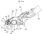
図4、図5(A)(B)に本実施例による吸口体本体を下から見たときの平面図(下面図)及び、中央断面図を示す。 FIGS. 4, 5 </ b> A and 5 </ b> B show a plan view (bottom view) and a central cross-sectional view when the mouthpiece body according to this embodiment is viewed from below.
403は吸口体下ケース201に設けられた床面開口部で、被清掃面に面する。401はバンパー、400は固定刷毛、404は後方車輪である。405は固定刷毛前方に設けた刷毛逃げ部A、406は固定刷毛後方に設けた刷毛逃げ部Bである。207は吸口体を持ち上げたときに自動的に停止するための安全スイッチであり、207Aは被清掃面に設置されているかを検出するための床面検出車輪である。
220は下ケース201の下面側に位置する軸受け押さえ部材407を開閉するための係止部材であり、上ケース200と下ケース201から張り出した支持部を回動軸とし、組み付けにより上下方向で支持し、係止部材220の抜け外れを規制している。
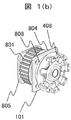
図1(A)に本実施例による回転清掃体204及び、動力伝達機構101を示す。
FIG. 1A shows a
回転清掃体204の清掃部材107は、繊維等による刷毛105の他、軟質のブレード104を用いて構成することができ、刷毛105やブレード104をそれぞれ単独で、或いは刷毛105とブレード104とを混在させて構成することができる。また、筒状基体106を形成する部材で一体に成形した突出部で清掃部材107を構成してもよい。いずれにしても、清掃部材107は筒状基体106の外周面から外方に突出するように構成される。
The
回転清掃体204の両端には、回転清掃体204を吸口体本体へ保持する噛合い部A110(駆動側端部に備える)、軸受台111(回転支持部材)(非駆動側端部に備える)が設けられており、その外周には刷毛台109に斜めに接着固定された刷毛A108が設けられる。刷毛A108は密度が清掃部材107よりも大きく設定されている。
At both ends of the
図1(B)に本実施例による図1(A)の動力伝達機構101の拡大図を示す。図1(C)に図1(A)のP拡大図を示す。
FIG. 1B shows an enlarged view of the
噛合い部A110は、下ケース201内部に設けられた動力伝達機構101に設けられた噛合い部B408と凹凸にて結合し、回転清掃体204へ回動力を伝える役割を果たす。ここで、噛合い部A110と噛合い部B408は同じ色相になるようにする。
The meshing part A <b> 110 is coupled to the meshing part B <b> 408 provided in the
図6に本実施例による回転清掃体の軸受台側の断面図を示す。 FIG. 6 is a sectional view of the rotary cleaning body on the bearing stand side according to the present embodiment.
軸601は筒状基体106と同一に回転するように固定されており、軸601は軸受台111に回転可能に軸支されている。ここで、軸受台111は噛合い部A110及び噛合い部B408と異なる色相となっている。
The
図8は本発明の実施形態の一例に係わる電気掃除機の動力伝達機構101の断面図である。
FIG. 8 is a cross-sectional view of the
プーリ801の回転軸には金属軸802がインサート成型されており、中心部にオイルメタル803を配置した保持部材A804、保持部材B805により両端支持で保持されている。さらに金属軸802の端部には噛合い部A110が圧入されている。また、保持部材A804、保持部材B805とプーリ801の間はポリスライダワッシャ806を挟むことで、摩擦の低減を図っている。
A
また、プーリ801と保持部材A804の間には、保持部材A804より延ばしたリブ808と、噛合い部A110の凹凸部と逆方向に設けたフランジ809により、ごみ溜め溝807を設けることにより、動力伝達機構へ侵入した塵埃が、金属軸802の摺動部へ入り込むのを防止している。ここで、リブ808の先端よりも、フランジ809の最外周の位置は低い位置となっている。
Further, between the
次に本実施例における電気掃除機の動作について説明する。 Next, operation | movement of the vacuum cleaner in a present Example is demonstrated.
掃除機使用者が図3に示すハンドルグリップ303に設置された手元スイッチ304を操作すると、操作されたスイッチに従った作動モードで電気掃除機本体301内の電動送風機が運転を開始する。電動送風機によって発生した吸引力は、ホース体302、延長管305を通って吸口体306に到達する。それと同時に、ホース体302および延長管305に設けられた電源線から供給された電源が、回路基板(図示せず)を介して電動機205を駆動する。
When the vacuum cleaner user operates the
電動機205と大プーリ209、シャフト211、小プーリ210、動力伝達機構101、ベルト410で連結している回転清掃体204が回転することにより、回転清掃体204の清掃部材107である刷毛105やブレード104によって被掃除面からごみや塵埃を掻き上げて吸い込む。
When the
また、回転清掃体204が回転中、常に刷毛A108が非清掃面へ接触しているので、吸口体306へは前進する力が働き、操作力が軽くなる。ここで、刷毛A108の密度や、硬さ、高さ等を変更することで操作力の調整が可能となる。
Further, since the brush A108 is always in contact with the non-cleaning surface while the
また、刷毛A108を斜めに貼り付け、刷毛の目を斜めにすることで、回転清掃体が回転した際、その目に沿い塵埃を回転清掃体室212中心方向へと移動させることも可能である。
Further, by applying the brush A108 obliquely and making the brush eyes oblique, when the rotary cleaning body rotates, it is also possible to move the dust toward the center of the rotary cleaning
更に、吸口体306を前方へ操作した際、吸口体306底面の固定刷毛400は刷毛逃げ部B406へと倒れ、また、後方へ動作した場合は刷毛逃げ部A405へと倒れることにより床面との間に挟まることはない。これにより、固定刷毛400が吸口体306底面との間に挟まり、操作力が重くなることを、防ぐことが可能となる。
Further, when the
また、刷毛逃げ部A405、刷毛逃げ部B406を固定刷毛400の前後のみとすることで、刷毛逃げ部A405、刷毛逃げ部B406を設けても、回転清掃体収納室212内の静圧は、刷毛逃げ部A405、刷毛逃げ部B406が無いときと変わらない。これにより、刷毛逃げ部A405、刷毛逃げ部B406を設けても、吸込み性能は変わることはない。
Further, by setting the brush escape portion A405 and the brush escape portion B406 only before and after the fixed
しかしながら、回転清掃体204の刷毛A108へは、清掃部材107に比べ、全周が刷毛A108で構成される為、糸くずなどの繊維状のものや、髪の毛等が絡み付き易い問題点もある。
However, since the entire circumference of the brush A108 of the
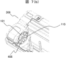
図7に本実施例による回転清掃体204のメンテナンスでの取り外し方・取り付け方を示す。
FIG. 7 shows how to remove and attach the
まず、吸口体306の下面側を上方に向ける。係止部材220の操作部220Aに操作者の指を添え、吸口体306中央側から外側に回動し、軸受押さえ部材407と係止部220の係合を解除する(イ)。そして、下ケース201から軸受押さえ部材407を外す(ロ)。
First, the lower surface side of the
次に、回転清掃体204を、上方に引き上げるとことにより、回転清掃体204の噛合い部A110と動力伝達機構101の噛合い部B408が外れ、吸口体306から離脱できる(ハ)。
Next, when the
これにより、回転清掃体204の刷毛A108に糸くず等が付着した際も容易に回転清掃体204を取り外し、簡単に糸くずなどの繊維状のものや、髪の毛等を取り除くことが可能となる。
Thereby, even when lint or the like adheres to the brush A108 of the
回転清掃体を取り付けるときは、取り外し時と逆の動作となり、回転清掃体204の噛合い部A110、動力伝達機構101の噛合い部B408の色相を揃えるようにし、吸口体306へ回転清掃体206を挿入する。このとき、回転清掃体204の噛合い部A110と軸受台111が異なる色相のため、使用者はその向きを間違えることなく、吸口体306へ回転清掃体204をはめることが出来る。次に軸受押さえ部材407をはめ、係止部材220をロックさせ係合させる。
When the rotary cleaning body is attached, the operation is the reverse of that at the time of removal, the hues of the meshing portion A110 of the
上述したように回転清掃体204の駆動側端部に存在する動力伝達機構101の噛合い部Aと非駆動側に存在する回転支持部材111は異色にされ、噛合い部Aが脱着自在に連結されるところの吸口体本体に設けられる動力伝達機構101の噛合い部B408は同じ色相になっているので、視覚判断で噛合い部A、Bの噛み合わせや、回転支持部材111の所定位置への取り付けが誤りなく容易に行うことができる。
As described above, the meshing portion A of the
本発明の各実施例は床移動型の掃除機だけでなく、アップライト式やスティック式の掃除機にも適用できる。モータ駆動方式の吸口体だけでなく、エアー駆動方式にも適用できる。 Each embodiment of the present invention can be applied not only to a floor moving type vacuum cleaner but also to an upright type or stick type vacuum cleaner. It can be applied not only to motor driven suction bodies but also to air driven systems.
101…動力伝達機構
104…ブレード
105…刷毛
106…筒状基体
107…清掃部材
108…刷毛A
109…刷毛台
110…噛合い部A
111…軸受台
200…上ケース
201…下ケース
202…第1の接続管
203…第2の接続管
204…回転清掃体
205…電動機
207…安全スイッチ
207A…床面検出車輪
208…電動機側プーリ
209…大プーリ
210…小プーリ
211…シャフト
212…回転清掃体収納室
218…開口
220…係止部材
220A…係止部材の操作部
301…電気掃除機本体
302…ホース体
303…ハンドルグリップ
304…手元スイッチ
305…延長管
306…吸口体
400…固定刷毛
401…バンパー
403…床面開口部
404…後方車輪
405…刷毛逃げ部A
406…刷毛逃げ部B
407…軸受押さえ部材
408…噛合い部B
410…ベルト
601…軸
801…プーリ
802…金属軸
803…オイルメタル
804…保持部材A
805…保持部材B
806…ポリスライダワッシャ
807…ごみ溜溝
808…保持部材Aから延ばしたリブ
809…噛合い部Bに配置したフランジ部
DESCRIPTION OF
109 ... brush stand 110 ... meshing part A
DESCRIPTION OF
406 ... Brush escape part B
407 ...
410 ... belt 601 ...
805 ... Holding member B
806...
Claims (2)
前記開口部より出し入れされ、かつ前記吸口体本体に取り外し自在に装着される回転可能な回転清掃体と、
前記吸口体本体に設けられ、前記回転清掃体を回転駆動する駆動源と、
前記駆動源の回転を前記回転清掃体に伝達する動力伝達機構を備え、
前記動力伝達機構は、前記回転清掃体の駆動側端部に設ける噛合い部Aと、前記噛合い部Aと脱着自在に連結し、かつ噛合い部Aに回転を伝えるところの前記吸口体本体に設ける噛合い部Bを有し、
前記回転清掃体は、前記駆動側端部の反対側である非駆動側端部を回動自在に支持し、かつ前記吸口体本体に取り外し自在に支持される軸受台を含む回転支持部材を有する電気掃除機用吸口体において、
前記回転清掃体の前記駆動側端部に存在する前記噛合い部Aと前記非駆動側端部に存在する前記回転支持部材を異色とし、前記駆動側端部に存在する前記噛合い部Aと前記吸口体本体に存在する前記噛合い部Bを同じ色相にしたことを特徴とする電気掃除機用吸口体。 A mouthpiece body having an opening on the bottom surface;
A rotatable rotary cleaning body that is taken in and out from the opening and is detachably attached to the mouthpiece body;
A drive source provided in the mouthpiece body for driving the rotary cleaning body to rotate;
A power transmission mechanism for transmitting rotation of the drive source to the rotary cleaning body;
The power transmission mechanism includes a meshing part A provided at a driving side end of the rotary cleaning body, and the mouthpiece body main body that is detachably connected to the meshing part A and transmits rotation to the meshing part A. Having a meshing part B provided in
The rotary cleaning body includes a rotation support member that includes a bearing base that rotatably supports a non-drive side end that is opposite to the drive side end and that is detachably supported by the mouthpiece body. In the vacuum cleaner mouthpiece,
The meshing part A present at the driving side end of the rotary cleaning body and the rotational support member present at the non-driving side end are different in color, and the meshing part A present at the driving side end The mouthpiece for a vacuum cleaner, wherein the meshing portion B present in the mouthpiece body has the same hue.
前記電気掃除機用吸口体が請求項1記載の電気掃除機用吸口体であることを特徴とする電気掃除機。 In a vacuum cleaner provided with a vacuum cleaner main body incorporating an electric blower, and a suction body for a vacuum cleaner connected to the vacuum cleaner main body directly or via a hose body,
The vacuum cleaner mouthpiece is the vacuum cleaner mouthpiece according to claim 1.
Priority Applications (1)
| Application Number | Priority Date | Filing Date | Title |
|---|---|---|---|
| JP2008157532A JP2009297377A (en) | 2008-06-17 | 2008-06-17 | Suction port body for vacuum cleaner, and vacuum cleaner |
Applications Claiming Priority (1)
| Application Number | Priority Date | Filing Date | Title |
|---|---|---|---|
| JP2008157532A JP2009297377A (en) | 2008-06-17 | 2008-06-17 | Suction port body for vacuum cleaner, and vacuum cleaner |
Publications (1)
| Publication Number | Publication Date |
|---|---|
| JP2009297377A true JP2009297377A (en) | 2009-12-24 |
Family
ID=41544887
Family Applications (1)
| Application Number | Title | Priority Date | Filing Date |
|---|---|---|---|
| JP2008157532A Pending JP2009297377A (en) | 2008-06-17 | 2008-06-17 | Suction port body for vacuum cleaner, and vacuum cleaner |
Country Status (1)
| Country | Link |
|---|---|
| JP (1) | JP2009297377A (en) |
Cited By (5)
| Publication number | Priority date | Publication date | Assignee | Title |
|---|---|---|---|---|
| JP2013022228A (en) * | 2011-07-21 | 2013-02-04 | Mitsubishi Electric Corp | Floor surface suction tool and vacuum cleaner using the same |
| CN103356128A (en) * | 2012-04-06 | 2013-10-23 | 联润科技股份有限公司 | Self-propelled cleaning device |
| JP2015012939A (en) * | 2013-07-04 | 2015-01-22 | 日立アプライアンス株式会社 | Suction port body of vacuum cleaner and vacuum cleaner using the same |
| JP2020110506A (en) * | 2019-01-17 | 2020-07-27 | 日立グローバルライフソリューションズ株式会社 | Suction port body of vacuum cleaner and vacuum cleaner including the same |
| CN111789531A (en) * | 2019-04-05 | 2020-10-20 | Seb公司 | Suction head and dust collector comprising same |
Citations (5)
| Publication number | Priority date | Publication date | Assignee | Title |
|---|---|---|---|---|
| JPH05309055A (en) * | 1991-08-16 | 1993-11-22 | Mitsubishi Electric Home Appliance Co Ltd | Floor brush of vacuum cleaner |
| JP3249188B2 (en) * | 1992-07-03 | 2002-01-21 | 三洋電機株式会社 | Floor suction device |
| JP2003135325A (en) * | 2001-10-31 | 2003-05-13 | Toshiba Tec Corp | Inlet port body and vacuum cleaner |
| JP2003135329A (en) * | 2001-10-31 | 2003-05-13 | Toshiba Tec Corp | Suction port body for vacuum cleaner and vacuum cleaner |
| JP2004337499A (en) * | 2003-05-19 | 2004-12-02 | Matsushita Electric Ind Co Ltd | Suction device for vacuum cleaner and vacuum cleaner using the same |
-
2008
- 2008-06-17 JP JP2008157532A patent/JP2009297377A/en active Pending
Patent Citations (5)
| Publication number | Priority date | Publication date | Assignee | Title |
|---|---|---|---|---|
| JPH05309055A (en) * | 1991-08-16 | 1993-11-22 | Mitsubishi Electric Home Appliance Co Ltd | Floor brush of vacuum cleaner |
| JP3249188B2 (en) * | 1992-07-03 | 2002-01-21 | 三洋電機株式会社 | Floor suction device |
| JP2003135325A (en) * | 2001-10-31 | 2003-05-13 | Toshiba Tec Corp | Inlet port body and vacuum cleaner |
| JP2003135329A (en) * | 2001-10-31 | 2003-05-13 | Toshiba Tec Corp | Suction port body for vacuum cleaner and vacuum cleaner |
| JP2004337499A (en) * | 2003-05-19 | 2004-12-02 | Matsushita Electric Ind Co Ltd | Suction device for vacuum cleaner and vacuum cleaner using the same |
Cited By (8)
| Publication number | Priority date | Publication date | Assignee | Title |
|---|---|---|---|---|
| JP2013022228A (en) * | 2011-07-21 | 2013-02-04 | Mitsubishi Electric Corp | Floor surface suction tool and vacuum cleaner using the same |
| CN103356128A (en) * | 2012-04-06 | 2013-10-23 | 联润科技股份有限公司 | Self-propelled cleaning device |
| JP2013215571A (en) * | 2012-04-06 | 2013-10-24 | Uni-Ring Tech Co Ltd | Self-propelled floor cleaning robot |
| JP2014208271A (en) * | 2012-04-06 | 2014-11-06 | 聯潤科技股▲ふん▼有限公司 | Self-traveling floor cleaning robot |
| JP2015012939A (en) * | 2013-07-04 | 2015-01-22 | 日立アプライアンス株式会社 | Suction port body of vacuum cleaner and vacuum cleaner using the same |
| JP2020110506A (en) * | 2019-01-17 | 2020-07-27 | 日立グローバルライフソリューションズ株式会社 | Suction port body of vacuum cleaner and vacuum cleaner including the same |
| CN111789531A (en) * | 2019-04-05 | 2020-10-20 | Seb公司 | Suction head and dust collector comprising same |
| CN111789531B (en) * | 2019-04-05 | 2023-06-23 | Seb公司 | Suction head and dust collector comprising same |
Similar Documents
| Publication | Publication Date | Title |
|---|---|---|
| JP5241458B2 (en) | Electric vacuum cleaner | |
| KR100470320B1 (en) | Steam cleaner having vacuum cleaning function | |
| RU2328206C1 (en) | Vertical type of vacuum cleaner with detachable electrical head | |
| EP1795107A2 (en) | Floor cleaner and method for controlling same | |
| US20030221281A1 (en) | Vacuum cleaner having a brush with a floor cloth | |
| JP2009045503A5 (en) | ||
| KR101116437B1 (en) | Suction nozzle and vacuum cleaner | |
| JP2009297377A (en) | Suction port body for vacuum cleaner, and vacuum cleaner | |
| US7690078B2 (en) | Vacuum cleaner with removable cleaning attachment | |
| JP2008278947A (en) | Vacuum cleaner | |
| JP2008000383A (en) | Vacuum cleaner | |
| JP2009017902A (en) | Suction port body of vacuum cleaner and vacuum cleaner using the same | |
| TWI667985B (en) | Self-propelled electric sweeper | |
| JP6121656B2 (en) | Vacuum cleaner and its suction port | |
| JP2008188375A (en) | Suction head for vacuum cleaner and vacuum cleaner using the same | |
| JP5147475B2 (en) | Vacuum cleaner and mouthpiece of vacuum cleaner | |
| JP2007175196A (en) | Vacuum cleaner | |
| KR200358084Y1 (en) | Portable cleaner for vehicles | |
| KR200336735Y1 (en) | steam dustcloth combined use vacuum cleaner | |
| JP2021176414A (en) | Suction port body for vacuum cleaner | |
| JP7470574B2 (en) | Suction port body of a vacuum cleaner and a vacuum cleaner equipped with the same | |
| JP5147797B2 (en) | Vacuum cleaner mouthpiece and vacuum cleaner | |
| JP5622830B2 (en) | Vacuum cleaner mouthpiece | |
| JP2000197595A (en) | Multipurpose ancillary device for vacuum cleaner and galvanic belt and improved household electric appliance usable as singly movable type device | |
| JP5154628B2 (en) | Suction body of vacuum cleaner and vacuum cleaner using the same |
Legal Events
| Date | Code | Title | Description |
|---|---|---|---|
| A621 | Written request for application examination |
Free format text: JAPANESE INTERMEDIATE CODE: A621 Effective date: 20100526 |
|
| A977 | Report on retrieval |
Free format text: JAPANESE INTERMEDIATE CODE: A971007 Effective date: 20120116 |
|
| A131 | Notification of reasons for refusal |
Free format text: JAPANESE INTERMEDIATE CODE: A131 Effective date: 20120124 |
|
| A131 | Notification of reasons for refusal |
Free format text: JAPANESE INTERMEDIATE CODE: A131 Effective date: 20121002 |
|
| A02 | Decision of refusal |
Free format text: JAPANESE INTERMEDIATE CODE: A02 Effective date: 20130618 |