JP2009287632A - Floating type disc brake and motorcycle - Google Patents
Floating type disc brake and motorcycle Download PDFInfo
- Publication number
- JP2009287632A JP2009287632A JP2008139358A JP2008139358A JP2009287632A JP 2009287632 A JP2009287632 A JP 2009287632A JP 2008139358 A JP2008139358 A JP 2008139358A JP 2008139358 A JP2008139358 A JP 2008139358A JP 2009287632 A JP2009287632 A JP 2009287632A
- Authority
- JP
- Japan
- Prior art keywords
- bracket
- plate
- disc brake
- engaged
- fixing
- Prior art date
- Legal status (The legal status is an assumption and is not a legal conclusion. Google has not performed a legal analysis and makes no representation as to the accuracy of the status listed.)
- Pending
Links
Images


Classifications
-
- F—MECHANICAL ENGINEERING; LIGHTING; HEATING; WEAPONS; BLASTING
- F16—ENGINEERING ELEMENTS AND UNITS; GENERAL MEASURES FOR PRODUCING AND MAINTAINING EFFECTIVE FUNCTIONING OF MACHINES OR INSTALLATIONS; THERMAL INSULATION IN GENERAL
- F16D—COUPLINGS FOR TRANSMITTING ROTATION; CLUTCHES; BRAKES
- F16D65/00—Parts or details
- F16D65/02—Braking members; Mounting thereof
- F16D65/12—Discs; Drums for disc brakes
- F16D65/123—Discs; Drums for disc brakes comprising an annular disc secured to a hub member; Discs characterised by means for mounting
-
- F—MECHANICAL ENGINEERING; LIGHTING; HEATING; WEAPONS; BLASTING
- F16—ENGINEERING ELEMENTS AND UNITS; GENERAL MEASURES FOR PRODUCING AND MAINTAINING EFFECTIVE FUNCTIONING OF MACHINES OR INSTALLATIONS; THERMAL INSULATION IN GENERAL
- F16D—COUPLINGS FOR TRANSMITTING ROTATION; CLUTCHES; BRAKES
- F16D65/00—Parts or details
- F16D65/02—Braking members; Mounting thereof
- F16D2065/13—Parts or details of discs or drums
- F16D2065/1304—Structure
- F16D2065/1316—Structure radially segmented
-
- F—MECHANICAL ENGINEERING; LIGHTING; HEATING; WEAPONS; BLASTING
- F16—ENGINEERING ELEMENTS AND UNITS; GENERAL MEASURES FOR PRODUCING AND MAINTAINING EFFECTIVE FUNCTIONING OF MACHINES OR INSTALLATIONS; THERMAL INSULATION IN GENERAL
- F16D—COUPLINGS FOR TRANSMITTING ROTATION; CLUTCHES; BRAKES
- F16D65/00—Parts or details
- F16D65/02—Braking members; Mounting thereof
- F16D2065/13—Parts or details of discs or drums
- F16D2065/134—Connection
- F16D2065/1348—Connection resilient
-
- F—MECHANICAL ENGINEERING; LIGHTING; HEATING; WEAPONS; BLASTING
- F16—ENGINEERING ELEMENTS AND UNITS; GENERAL MEASURES FOR PRODUCING AND MAINTAINING EFFECTIVE FUNCTIONING OF MACHINES OR INSTALLATIONS; THERMAL INSULATION IN GENERAL
- F16D—COUPLINGS FOR TRANSMITTING ROTATION; CLUTCHES; BRAKES
- F16D65/00—Parts or details
- F16D65/02—Braking members; Mounting thereof
- F16D2065/13—Parts or details of discs or drums
- F16D2065/134—Connection
- F16D2065/1356—Connection interlocking
- F16D2065/1368—Connection interlocking with relative movement both radially and axially
-
- F—MECHANICAL ENGINEERING; LIGHTING; HEATING; WEAPONS; BLASTING
- F16—ENGINEERING ELEMENTS AND UNITS; GENERAL MEASURES FOR PRODUCING AND MAINTAINING EFFECTIVE FUNCTIONING OF MACHINES OR INSTALLATIONS; THERMAL INSULATION IN GENERAL
- F16D—COUPLINGS FOR TRANSMITTING ROTATION; CLUTCHES; BRAKES
- F16D65/00—Parts or details
- F16D65/02—Braking members; Mounting thereof
- F16D2065/13—Parts or details of discs or drums
- F16D2065/134—Connection
- F16D2065/1392—Connection elements
Abstract
Description
本発明は、フローティング型ディスクブレーキ、特に、自動二輪車の車輪の軸部に装着されるフローティング型ディスクブレーキ及びそれを備えた自動二輪車に関する。 The present invention relates to a floating type disc brake, and more particularly to a floating type disc brake mounted on a shaft portion of a wheel of a motorcycle and a motorcycle including the same.
自動二輪車の制動装置として、従来からフローティング型ディスクブレーキが採用されている。このフローティング型ディスクブレーキは、例えば特許文献1に示されるように、パッドに挟まれる摩擦面を有するディスクプレートと、ディスクプレートの内周側に配置され車輪の軸部に取り付けられるブラケットと、を有している。そして、ディスクプレートは、ブラケットに対して複数のフローティングピンを介して浮動状態で支持されている。 Conventionally, a floating disc brake has been adopted as a braking device for a motorcycle. For example, as shown in Patent Document 1, this floating disc brake has a disc plate having a friction surface sandwiched between pads, and a bracket that is disposed on the inner peripheral side of the disc plate and is attached to a wheel shaft. is doing. The disk plate is supported in a floating state with respect to the bracket via a plurality of floating pins.
また、軽量化を目的とした別のタイプのフローティング型ディスクブレーキとして、例えば、特許文献2に示されるように、ディスクプレートとブラケットとを、突出部と凹部とによって連結するようにしたものも提案されている。具体的には、ディスクプレートの内周縁部に内側に突出する複数の突出部が設けられるとともに、ブラケットの外周縁部に複数の凹部が形成されており、各突出部が対応する凹部に係合されている。そして、ブラケットのディスクプレートに対する軸方向の移動を規制するために、突出部と凹部とが係合する部分の両側面に、係合部分を覆うように固定板が設けられている。この固定板は、係合部分を覆って周方向に延びており、その周方向の両端部がかしめにより固定されている。
特許文献1に示されたタイプのフローティング型ディスクブレーキでは、大きなブレーキトルク容量に耐え得るためには、多数のフローティングピンが必要となり、部品点数が多くなるだけではなく重量が増加する。 In the floating disc brake of the type shown in Patent Document 1, a large number of floating pins are required to withstand a large brake torque capacity, which increases not only the number of components but also the weight.
一方で、特許文献2に示されたタイプのフローティング型ディスクブレーキでは、特許文献1のタイプのブレーキに比較して各係合部分における接触面積(ディスクプレートの突出部とブラケットの凹部との周方向の接触面積)が増え、部品点数も減るので、特許文献1のタイプのブレーキに比較して軽量化が可能である。
On the other hand, in the floating type disc brake of the type shown in
しかし、市販されている自動二輪車のみならず、特にロードレースタイプの自動二輪車に用いられるディスクブレーキとしては、さらなる軽量化が求められている。 However, further weight reduction is demanded for disc brakes used not only for commercially available motorcycles but also for road race type motorcycles.
本発明の課題は、フローティング型ディスクブレーキにおいて、さらなる軽量化を実現することにある。 An object of the present invention is to realize further weight reduction in a floating disc brake.
本発明に係るフローティング型ディスクブレーキは、自動二輪車の車輪の軸部に装着されるものであって、ディスクプレートと、ブラケットと、固定板と、を備えている。ディスクプレートは、両側に制動用の第1摩擦面及び第2摩擦面を有する環状部と、環状部の内周縁部に形成された複数の係合部と、を有している。ブラケットは、車輪の軸部に取り付けられ、ディスクプレートの環状部の内側に配置されて、複数の係合部のそれぞれが係合する複数の被係合部が外周縁部に形成されている。固定板は、複数の係合部と被係合部とが係合した複数の係合個所に設けられ、ブラケットに対してディスクプレートが軸方向に移動するのを規制するための部材である。そして、固定板は、複数の係合個所の少なくとも一部においては第1及び第2摩擦面側の一方にのみ配置されている。 A floating type disc brake according to the present invention is attached to a shaft portion of a wheel of a motorcycle, and includes a disc plate, a bracket, and a fixed plate. The disk plate has an annular portion having a first friction surface and a second friction surface for braking on both sides, and a plurality of engaging portions formed on the inner peripheral edge of the annular portion. The bracket is attached to the wheel shaft and is disposed inside the annular portion of the disk plate, and a plurality of engaged portions to be engaged with each of the plurality of engaging portions are formed on the outer peripheral edge. The fixing plate is a member that is provided at a plurality of engagement points where the plurality of engaging portions and the engaged portion are engaged, and restricts the disk plate from moving in the axial direction with respect to the bracket. The fixing plate is disposed only on one side of the first and second friction surfaces in at least a part of the plurality of engaging portions.
このフローティング型ディスクブレーキでは、ディスクプレートの係合部とブラケットの被係合部とが係合しており、両者の係合により、ディスクプレートはブラケットに対して浮動状態で支持されている。ブレーキトルクは、ディスクプレートから係合部及び被係合部を介してブラケットに伝達され、さらに軸部を介して車輪に伝達される。これにより車輪が制動される。 In this floating type disc brake, the engaging portion of the disc plate and the engaged portion of the bracket are engaged, and the disc plate is supported in a floating state with respect to the bracket by the engagement therebetween. The brake torque is transmitted from the disc plate to the bracket via the engaging portion and the engaged portion, and further transmitted to the wheel via the shaft portion. This brakes the wheel.
ここで、フローティング型ディスクブレーキにおいて、ディスクプレートの係合部とブラケットの被係合部とが係合する部分ではブレーキトルクが伝達されるので、係合個所の摩耗を抑えるためには、係合部と被係合部との接触面積をより広く確保する必要がある。一方で、係合個所に設けられた固定板は、ブラケットに対するディスクプレートの軸方向のブレを抑えることが重要な機能であって、特に大きな外力が作用する訳ではない。 Here, in the floating type disc brake, the brake torque is transmitted at the portion where the engaging portion of the disc plate and the engaged portion of the bracket are engaged. It is necessary to secure a wider contact area between the portion and the engaged portion. On the other hand, the fixing plate provided at the engagement point is an important function to suppress the axial blur of the disk plate with respect to the bracket, and a particularly large external force does not act.
そこで、本発明では、固定板は、複数の係合個所の少なくとも一部において、片側の面にしか設けられていない。すなわち、すべての係合個所において両側の面に固定板が設けられているわけではない。このため、従来の構成に比較して部品点数が少なくなり、軽量化を実現することができる。 Therefore, in the present invention, the fixing plate is provided only on one surface at least at a part of the plurality of engaging portions. In other words, the fixing plates are not provided on both sides at all the engagement points. For this reason, compared with the conventional structure, a number of parts decreases and weight reduction is realizable.
以上のような本発明によれば、フローティング型ディスクブレーキのディスクプレートとブラケットの係合個所の構成が簡単になり、軽量化を図ることができる。 According to the present invention as described above, the configuration of the engaging portion between the disc plate and the bracket of the floating disc brake is simplified, and the weight can be reduced.
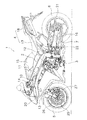
図1に本発明の一実施形態によるフローティング型ディスクブレーキが採用された自動二輪車を示す。図1は自動二輪車の左側面図である。 FIG. 1 shows a motorcycle employing a floating disc brake according to an embodiment of the present invention. FIG. 1 is a left side view of the motorcycle.
[全体構成]
この自動二輪車1は、ロードスポーツタイプの自動二輪車であり、車体フレーム2と、エンジンを含む駆動部3と、シート4と、前輪5及び後輪6と、駆動伝達部7とを備えている。
[overall structure]
The motorcycle 1 is a road sports type motorcycle and includes a
車体フレーム2は、周知の自動二輪車と同様の構成であるので詳細な説明は省略するが、概略、ヘッドパイプ10と、ヘッドパイプ10に接続された左右1対のタンクレール11と、タンクレール11の後端に接続され斜め後方に延びるリアフレーム12とを有している。ヘッドパイプ10にはフロントフォーク13が支持されている。フロントフォーク13の上端にはハンドル14が固定され、下端には前輪5が支持されている。また、タンクレール11の上部には燃料タンク15が配置され、下部には駆動部3が配置されている。タンクレール11の後端下部にはリアアーム16が上下揺動自在に連結されており、リアアーム16の後端に後輪6が支持されている。さらに、リアフレーム12の前部にシート4の一部を構成するメインシート17が配置され、後部には同様にシート4の一部を構成するタンデムシート18が配置されている。なお、車体フレーム2にはカウリング20が設けられている。
Since the
駆動伝達部7は、駆動部3の出力部である変速機の出力軸に固定されたドライブスプロケット(図示せず)と、後輪6の軸部に固定されたドリブンスプロケット21と、両スプロケット間に掛け渡されたチェーン22とから構成されている。
The
[ブレーキ装置]
この自動二輪車1において、前輪5の両側と後輪6の右側には、それぞれディスクブレーキ装置が設けられている。図1では、前輪5に設けられた左側のディスクブレーキ装置25のみが表れている。以下では、前輪のディスクブレーキ装置25のみについて説明するが、他のディスクブレーキ装置についても同様の構成である。
[Brake device]
In the motorcycle 1, disc brake devices are provided on both sides of the
このディスクブレーキ装置25は、前輪5の軸部にボルトにより固定されたフローティング型ディスクブレーキ(以下、単にディスクブレーキと記す)26と、油圧により作動するキャリパ27とを有している。
The
キャリパ27は、フロントフォーク13の下端部に固定されており、従来と同様の構成である。すなわち、互いに所定の間隔をあけて対向して配置された1対のパッドと、この1対のパッドのそれぞれを移動させるためのピストンと、を有している。ピストンは、ライダーのブレーキ操作によって、油圧により駆動されるようになっている。
The
<ディスクブレーキ>
ディスクブレーキ26は、図2以降に詳細に示すように、キャリパ27のパッドによって両面が挟持されるディスクプレート30と、前輪5の軸部に固定されたブラケット31と、複数の固定板32と、を有している。
<Disc brake>
As shown in detail in FIG. 2 and subsequent figures, the
ディスクプレート30は、ステンレス製あるいは鋼製で、図2及び図3に示すように、環状に形成された環状部35と、係合部としての6個の突出部37とを有している。
The
環状部35は、一方側の表面に第1摩擦面35aを有し、他方側の表面に第2摩擦面35bを有している。なお、図3はディスクプレート30のみを取り出して示したものである。ライダーによってブレーキ操作がなされたときには、各摩擦面35a,35bはキャリパ27のパッドと摺擦する。そして、このディスクプレート30には、放熱用及び軽量化のための多数の貫通孔36が形成されている。
The
6個の突出部37は、ディスクプレート30の内周縁部に、径方向内側に突出して形成されている。これらの突出部37は周方向に等間隔で形成されており、放射線状に内側に延びている。
The six projecting
ブラケット31は、アルミニウム製で、図2及び図4に示すように、概略環状に形成されている。なお、図4はブラケット31のみを取り出して示したものである。このブラケット31は、前述のように、前輪5の軸部に固定されるものであり、ディスクプレート30の内側に配置されている。ブラケット31の外周縁部には、ディスクプレート30の突出部37が係合可能な6個の凹部(被係合部)40が形成されている。ここで、6個の凹部40は、ディスクプレート30の突出部37と同様に、放射線状に延びて形成されている。
The
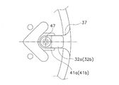
ブラケット31の6個の凹部40のさらに内周側には、軸方向に凹む6個の凹部(以下、段差部と記す)41a,41bが形成されている。段差部41a,41bは、後に詳述するように、固定板32を取り付ける際に回り止めとして機能する部分である。
On the inner peripheral side of the six
ここで、6個の段差部41a,41bのうちの3個の第1段差部41aは、ディスクプレート30の第1摩擦面35aと同じ側に形成され、残りの3個の第2段差部41bはディスクプレート30の第2摩擦面35bと同じ側に形成されている。そして、第1及び第2段差部41a,41bは周方向に交互に配置されている。具体的には、第1段差部41aは、第1摩擦面35a側において、周方向に120°の間隔で配置され、第2段差部41bは、第2摩擦面35b側において、隣り合う段差部41aの周方向の中心に配置され、周方向に120°の間隔で配置されている。
Here, of the six
また、第1及び第2段差部41a,41bは、すべて同一の形状であるので、ここでは、第1段差部41aの形状についてのみ説明する。第1段差部41aは、内周側の端部が半円状に形成され、各凹部40に向かって所定の幅で放射線状に延びている。第1段差部41aの幅は凹部40の幅より若干広く形成され、外周端部は凹部40の内周部の側部にまで延びている。また、第1段差部41aには1つのねじ孔42が形成されている。
Since the first and
ブラケット31の内周部には、このブラケット31を前輪5の軸部に固定するためのボルトが挿通する3つの孔43が形成されている。3つの孔43のそれぞれは、隣り合う2つの凹部40の周方向の中心に配置されている。さらに、ブラケット31には、軽量化のための多数の開口部が形成されている。
Three
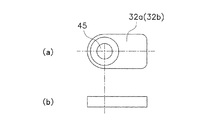
複数の固定板32のそれぞれは、係合箇所を拡大して示す図5及び固定板32自体を示す図6から明らかなように、一端が半円形状の短冊状の部材である。この複数の固定板32は、ブラケット31の第1段差部41aに装着された第1固定板32aと、ブラケット31の第2段差部41bに装着された第2固定板32bとからなる。第1固定板32aと第2固定板32bとは配置される場所が異なるだけであって、全く同一の構成である。
Each of the plurality of fixing
第1及び第2固定板32a,32bは第1及び第2段差部41a,41bの幅より若干狭く、ディスクプレート30の突出部37とほぼ同じ幅を有している。そして、第1及び第2固定板32a,32bの長手方向の一端側には貫通孔45が形成されている。この貫通孔45の一方側には、テーパ状の座ぐりが形成されている。このテーパ状の座ぐり部分の座ぐり径は、後述する皿ねじの頭部が嵌り込む径となっている。
The first and
第1及び第2固定板32a,32bは、貫通孔45を挿通し、ブラケット31の第1及び第2段差部41a,41bのねじ孔42に螺合する皿ねじ47によりブラケット31に固定されている。そして、第1及び第2固定板32a,32bをブラケット31に固定した状態では、各固定板32a,32bは放射状に延び、径方向外側部分がディスクプレート30の突出部37の一方側の面を覆っている。
The first and
以上のように、第1固定板32aは第1段差部41aに固定され、第2固定板32bは第2段差部41bに固定されているので、第1固定板32aと第2固定板32bとは円周方向に交互に配置されていることになる。そして、これらの両固定板32a,32bにより、ブラケット31に対するディスクプレート30の軸方向の移動が規制されている。
As described above, since the
ここで、ディスクプレート30、ブラケット31及びその段差部41a,41bの軸方向の寸法(厚み)について説明する。ディスクプレート30は、円周方向に交互にではあるが、両側から第1及び第2固定板32a,32bによって挟まれることになる。そして、両固定板32a,32bをブラケット31に固定した際に、ディスクプレート30が両固定板32a,32bによって押しつけられないようにする必要がある。
Here, the dimension (thickness) in the axial direction of the
そこで、ブラケット31、段差部41a,41b及びディスクプレート30の厚みの寸法関係は、最大公差を考慮しても、以下のような関係になっている。
Therefore, the dimensional relationship among the thicknesses of the
(ブラケット31の厚み)−(段差部41a)−(段差部41b)≧(ディスクプレート30の厚み)
[組み立て]
以上のような構成のディスクブレーキを組み立てる場合は、まずブラケット31の片面側に3個の第1固定板32aを固定する。すなわち、ブラケット31の第1段差部41aに、皿ねじ47により3個の第1固定板32aをそれぞれ取り付ける。そして次に、この第1固定板32aが取り付けられた側を下にしてブラケット31を作業台等の上に配置し、その上にディスクプレート30を載置する。次に、ブラケット31の第2段差部41bに3個の第2固定板32bを皿ねじ47によりそれぞれ取り付ける。
(Thickness of bracket 31) − (stepped
[assembly]
When assembling the disc brake having the above configuration, first, the three
以上の組み立て作業時に、第1及び第2固定板32a,32bは1個の皿ねじ47のみによってブラケット31に固定されるので、皿ねじ47を締め込む際に、第1及び第2固定板32a,32bが皿ねじ47の締め込みに伴って供回りするおそれがある。
During the above assembling operation, the first and
しかし、本実施形態では、第1及び第2段差部41a,41bに第1及び第2固定板32a,32bが嵌め込まれているので、皿ねじ47の締め込み時に、各固定板32a,32bが各段差部41a,41bの壁に当接し、皿ねじ47が供回りするのを防止することができ、作業性が向上する。
However, in this embodiment, since the first and
[本実施形態の効果]
(a) ディスクプレート30とブラケット31とが係合している個所には、片面側にしか第1固定板32aまたは第2固定板32bが設けられていないので、係合個所の両面に固定板が設けられた従来の装置に比較して軽量化を実現することができる。また、部品点数が削減されるので、組み付け作業の容易化、加工及び組み付け精度の管理の容易化を図ることができる。
[Effect of this embodiment]
(a) Since the
(b) 第1固定板32aと第2固定板32bとが円周方向に交互に配置されているので、回転時の動的アンバランスを避けることができる。
(b) Since the first fixed
(c) 各固定板32a,32bがブラケット31側で固定されているので、すなわちディスクプレート30側に固定されていないので、ディスクプレート30の摩擦面を広く確保することができる。したがって、発熱、摩耗の面で有利となる。
(c) Since each of the fixed
(d) 各固定板32a,32bの固定に際して、従来のように円周方向における2カ所の固定とは異なり、1個所のみによる固定であるので、固定板が小さくてすむし、部品点数も少ない。
(d) When fixing each of the fixing
(e) 本実施形態では、各固定板32a,32bを1個所のみでブラケット31に固定している。このため、前述のように、皿ねじ47を締め込む際に、各固定板32a,32bが供回りするおそれがある。しかし、各段差部41a,41bに各固定板32が嵌め込まれているので、各段差部41a,41bが回り止めとして機能する。したがって、各固定板32a,32bを皿ねじ47により固定する際に、組み付け用の特別なジグを用意する必要がない。
(e) In the present embodiment, each fixing
(f) 各固定板32a,32bを皿ねじ47により固定しているので、従来のかしめに比較して軽量化が可能になる。また、皿ねじ47によって、ねじの頭部表面と各固定板32a,32bの表面とがほぼ面一になっている。このため、皿ねじ47と他の部材との干渉を避けるための配慮が不要になり、設計の自由度が増す。
(f) Since the fixing
[他の実施形態]
(a) 図7に別の実施形態を示す。この実施形態では、第1固定板の形状と、板ばねを追加した点のみが前記実施形態と異なり、他の構成は同じである。
[Other Embodiments]
(a) FIG. 7 shows another embodiment. In this embodiment, only the shape of the first fixing plate and the point of adding a leaf spring are different from the above embodiment, and the other configurations are the same.
図7に示す実施形態の第1固定板32cの裏面(ディスクプレート30と対向する側の面)において、凹部50が形成されており、この凹部50にはディスクプレート30を第1固定板32cから離れる方向に付勢する板ばね51が配置されている。なお、この板ばね51は、片側の面に取り付けられた第1固定板32cのみに配置されている。
A
ここでは、ディスクプレート30が板ばね51によって一方側に常に付勢されているので、ディスクプレート30の軸方向のブレを抑えることができる。
Here, since the
(b) 前記実施形態では、6個所の係合個所において、片面側に3個ずつの第1固定板32aと第2固定板32bを設けたが、係合個所の個数や固定板の個数、配置については限定されない。例えば、8個所の係合個所を設け、片面側にそれぞれ3個ずつの固定板を設けても良い。この場合は、固定板が装着されない2つの係合個所が存在することになるが、3個ずつ計6個の固定板でディスクプレートの軸方向の移動が規制されるので、不具合はない。
(b) In the above-described embodiment, three
(c) 前記実施形態では、ディスクプレート30に突出部37を設け、ブラケット31に凹部40を設けたが、これらは逆であっても良い。但し、前述のように、一般的に、ディスクプレート30はステンレスあるいは鋼製であり、ブラケット31はアルミニウム製であるので、強度的な面を考慮すると、ディスクプレート30に突出部を設けた方が有利である。
(c) In the above embodiment, the
(d) 前記実施形態では、1つの固定板を1つの皿ねじによって固定するようにしたが、従来と同様に1つの固定板を2つのねじ部材、あるいはかしめ等によって固定するようにしても良い。この場合は、前記実施形態に比較して重量が増加することになるが、従来のように両面に固定板を設ける場合に比較して軽量化されることになる。 (d) In the embodiment described above, one fixing plate is fixed by one flat head screw. However, one fixing plate may be fixed by two screw members or caulking as in the conventional case. . In this case, the weight is increased as compared with the above embodiment, but the weight is reduced as compared with the case where the fixing plates are provided on both sides as in the conventional case.
また、固定用のねじ部材は、皿ねじに限定されるものではなく、頭部の高さに低いねじ部材等を用いることで、ほぼ同様の効果が得られる。 The fixing screw member is not limited to a countersunk screw, and substantially the same effect can be obtained by using a screw member having a low head height.
(e) 前記実施形態では、各固定板32a,32bを固定する際の回り止めとして、第1及び第2段差部41a,41bを形成したが、回り止めのための構成は段差部に限定されない。例えば、各固定板32a,32bの両側部に近接するように、突起部を設けてもよい。
(e) In the above embodiment, the first and
1 自動二輪
2 車体フレーム
3 駆動部
4 シート
5 前輪
6 後輪
7 駆動伝達部
26 フローティング形ディスクブレーキ
30 ディスクプレート
31 ブラケット
32a,32b,32c 固定板
35 環状部
35a,35b 摩擦面
37 突出部(係合部)
40 凹部(被係合部)
41a,41b 段差部
42 ねじ孔
47 皿ねじ
DESCRIPTION OF SYMBOLS 1
40 Recess (engaged part)
41a, 41b Stepped
Claims (12)
両側に制動用の第1摩擦面及び第2摩擦面を有する環状部と、前記環状部の内周縁部に形成された複数の係合部と、を有するディスクプレートと、
前記車輪の軸部に取り付けられ、前記ディスクプレートの環状部の内側に配置されて、複数の前記係合部のそれぞれが係合する複数の被係合部が外周縁部に形成されたブラケットと、
複数の前記係合部と前記被係合部とが係合した複数の係合個所に設けられ、前記ブラケットに対して前記ディスクプレートが軸方向に移動するのを規制するための部材であって、複数の前記係合個所の少なくとも一部においては前記第1及び第2摩擦面側の一方にのみ配置されている固定板と、
を備えたフローティング型ディスクブレーキ。 A floating disc brake mounted on the axle of a motorcycle wheel,
A disc plate having an annular portion having a first friction surface and a second friction surface for braking on both sides, and a plurality of engaging portions formed on the inner peripheral edge of the annular portion;
A bracket attached to the wheel shaft and disposed inside the annular portion of the disk plate, wherein a plurality of engaged portions engaged with each of the plurality of engaging portions are formed on an outer peripheral edge portion; ,
A member for restricting the disk plate from moving in the axial direction with respect to the bracket, provided at a plurality of engaging portions where the plurality of engaging portions and the engaged portion are engaged. A fixing plate disposed only on one of the first and second friction surface sides in at least a part of the plurality of engagement points;
Floating disc brake with
前記ブラケットの被係合部は前記突出部が係合する凹部である、
請求項1又は2に記載のフローティング型ディスクブレーキ。 The engaging portion of the disk plate is a protruding portion protruding radially inward,
The engaged portion of the bracket is a recess with which the protruding portion is engaged.
The floating disc brake according to claim 1 or 2.
前記雌ねじに螺合し、前記第1固定板及び前記第2固定板を前記ブラケットに固定するためのねじ部材をさらに備えている、
請求項4に記載のフローティング型ディスクブレーキ。 A female screw is formed at a position where each of the fixing plates is fixed in the bracket,
A screw member that is screwed to the female screw and that fixes the first fixing plate and the second fixing plate to the bracket;
The floating disc brake according to claim 4.
前記ブラケットの複数の被係合部は、前記3つの固定部のそれぞれの円周方向の間に2つずつ形成されている、
請求項1に記載のフローティング型ディスクブレーキ。 The bracket is formed in an annular shape, and three fixing portions for fixing the bracket to the shaft portion of the wheel are arranged at equal intervals in the circumferential direction at an inner peripheral end portion.
A plurality of engaged portions of the bracket are formed two each between the circumferential directions of the three fixing portions,
The floating disc brake according to claim 1.
前記車体フレームに支持されたエンジンを含む駆動部と、
前記駆動部の上方に配置されたシートと、
前記車体フレームに支持された前輪及び後輪と、
前記駆動部から動力を前記前輪又は前記後輪に伝達する駆動伝達部と、
を備え、
前記前輪及び前記後輪の少なくとも一方には、車輪の軸部に装着されるフローティング型ディスクブレーキが設けられており、
前記フローティング型ディスクブレーキは、
両側に第1摩擦面及び第2摩擦面を有する環状部と、前記環状部の内周縁部に形成された複数の係合部と、を有するディスクプレートと、
前記車輪の軸部に取り付けられ、前記ディスクプレートの環状部の内側に配置されて、複数の前記係合部のそれぞれが係合する複数の被係合部が外周縁部に形成されたブラケットと、
複数の前記係合部と前記被係合部とが係合した複数の係合個所に設けられ、前記ブラケットに対して前記ディスクプレートが軸方向に移動するのを規制するための部材であって、複数の前記係合個所の少なくとも一部においては前記第1及び第2摩擦面側の一方にのみ配置されている固定板と、
を有している、
自動二輪車。 Body frame,
A drive unit including an engine supported by the vehicle body frame;
A seat disposed above the drive unit;
Front and rear wheels supported by the body frame;
A drive transmission unit for transmitting power from the drive unit to the front wheel or the rear wheel;
With
At least one of the front wheel and the rear wheel is provided with a floating disc brake that is mounted on a wheel shaft,
The floating disc brake is
A disk plate having an annular portion having a first friction surface and a second friction surface on both sides, and a plurality of engaging portions formed on an inner peripheral edge of the annular portion;
A bracket attached to the wheel shaft and disposed inside the annular portion of the disk plate, wherein a plurality of engaged portions engaged with each of the plurality of engaging portions are formed on an outer peripheral edge portion; ,
A member for restricting the disk plate from moving in the axial direction with respect to the bracket, provided at a plurality of engaging portions where the plurality of engaging portions and the engaged portion are engaged. A fixing plate disposed only on one of the first and second friction surface sides in at least a part of the plurality of engagement points;
have,
Motorcycle.
Priority Applications (2)
| Application Number | Priority Date | Filing Date | Title |
|---|---|---|---|
| JP2008139358A JP2009287632A (en) | 2008-05-28 | 2008-05-28 | Floating type disc brake and motorcycle |
| EP09004138A EP2128476A1 (en) | 2008-05-28 | 2009-03-23 | Floating type disc brake |
Applications Claiming Priority (1)
| Application Number | Priority Date | Filing Date | Title |
|---|---|---|---|
| JP2008139358A JP2009287632A (en) | 2008-05-28 | 2008-05-28 | Floating type disc brake and motorcycle |
Publications (1)
| Publication Number | Publication Date |
|---|---|
| JP2009287632A true JP2009287632A (en) | 2009-12-10 |
Family
ID=41010851
Family Applications (1)
| Application Number | Title | Priority Date | Filing Date |
|---|---|---|---|
| JP2008139358A Pending JP2009287632A (en) | 2008-05-28 | 2008-05-28 | Floating type disc brake and motorcycle |
Country Status (2)
| Country | Link |
|---|---|
| EP (1) | EP2128476A1 (en) |
| JP (1) | JP2009287632A (en) |
Cited By (2)
| Publication number | Priority date | Publication date | Assignee | Title |
|---|---|---|---|---|
| JP2012202484A (en) * | 2011-03-25 | 2012-10-22 | Fanuc Ltd | Brake disk for rotary table |
| WO2013129005A1 (en) | 2012-02-28 | 2013-09-06 | サンスター技研株式会社 | Brake disk |
Families Citing this family (3)
| Publication number | Priority date | Publication date | Assignee | Title |
|---|---|---|---|---|
| US10190647B2 (en) * | 2014-12-05 | 2019-01-29 | Yuan-Hung WEN | Brake disc |
| TWI547654B (en) * | 2015-06-16 | 2016-09-01 | 陳惠絹 | Brake disk |
| IT202000006805A1 (en) | 2020-04-01 | 2021-10-01 | Endurance Adler S P A | DISC BRAKE. |
Family Cites Families (6)
| Publication number | Priority date | Publication date | Assignee | Title |
|---|---|---|---|---|
| JPH0730801B2 (en) | 1986-05-15 | 1995-04-10 | ヤマハ発動機株式会社 | Disk brake disk plate |
| DE19528434B4 (en) * | 1995-08-02 | 2004-04-15 | Bayerische Motoren Werke Ag | brake disc |
| ITMI981136A1 (en) * | 1998-05-21 | 1999-11-21 | Brembo Engineering S P A | BRAKE DISC WITH HIGH RESISTANCE TO WEAR AND THERMAL-MECHANICAL STRESS |
| DE10157283C1 (en) * | 2001-11-22 | 2003-06-26 | Porsche Ag | Brake disc for motor vehicle has rotor made of ceramic material with axially spaced rings clamped to carrier by bolted plates |
| US7789206B2 (en) * | 2002-04-23 | 2010-09-07 | Freni Brembo S.P.A. | Disk for a disk brake |
| JP4462537B2 (en) | 2004-03-31 | 2010-05-12 | 株式会社ユタカ技研 | Floating disc brake |
-
2008
- 2008-05-28 JP JP2008139358A patent/JP2009287632A/en active Pending
-
2009
- 2009-03-23 EP EP09004138A patent/EP2128476A1/en not_active Withdrawn
Cited By (4)
| Publication number | Priority date | Publication date | Assignee | Title |
|---|---|---|---|---|
| JP2012202484A (en) * | 2011-03-25 | 2012-10-22 | Fanuc Ltd | Brake disk for rotary table |
| WO2013129005A1 (en) | 2012-02-28 | 2013-09-06 | サンスター技研株式会社 | Brake disk |
| JP2013177906A (en) * | 2012-02-28 | 2013-09-09 | Sunstar Engineering Inc | Brake disc |
| US9897155B2 (en) | 2012-02-28 | 2018-02-20 | Sunstar Engineering Inc. | Brake disk |
Also Published As
| Publication number | Publication date |
|---|---|
| EP2128476A1 (en) | 2009-12-02 |
Similar Documents
| Publication | Publication Date | Title |
|---|---|---|
| JP2009287632A (en) | Floating type disc brake and motorcycle | |
| KR101294035B1 (en) | Structure of axle assembly for a driving wheel | |
| JP2005121174A (en) | Opposed piston type disk brake | |
| WO2015092834A1 (en) | Saddled vehicle | |
| JP2007064296A (en) | Disc brake device and motorcycle equipped with this disc brake device | |
| JP2004286216A (en) | One piece sliding brake caliper | |
| EP2971839B1 (en) | Tensioned brake pad | |
| JP5528288B2 (en) | Vehicle speed detection device or vehicle speed detection rotor | |
| JP2012072842A (en) | Floating type disc brake | |
| JP4595581B2 (en) | Hub unit | |
| JP3934095B2 (en) | Radial mount type disc brake | |
| JP4673564B2 (en) | Disc brake | |
| JP2005249133A5 (en) | ||
| JP5297341B2 (en) | Caliper body for disc brakes for vehicles | |
| JP4932651B2 (en) | Opposite piston type disc brake | |
| JP2009250330A (en) | Brake disk | |
| JP2008138737A (en) | Disc brake | |
| JP2004353723A (en) | Caliper body mounting structure of disc brake for vehicle | |
| US20070051569A1 (en) | Brake system for vehicle | |
| JP3882138B2 (en) | Disc brake | |
| JP2005083509A (en) | Disk brake | |
| JP2016079986A (en) | Disc brake device | |
| JP6411879B2 (en) | Saddle riding vehicle | |
| JP2012072843A (en) | Floating type disc brake | |
| JP5812257B2 (en) | Disc brake device |