JP2009284635A - Drive system - Google Patents
Drive system Download PDFInfo
- Publication number
- JP2009284635A JP2009284635A JP2008133253A JP2008133253A JP2009284635A JP 2009284635 A JP2009284635 A JP 2009284635A JP 2008133253 A JP2008133253 A JP 2008133253A JP 2008133253 A JP2008133253 A JP 2008133253A JP 2009284635 A JP2009284635 A JP 2009284635A
- Authority
- JP
- Japan
- Prior art keywords
- drive
- component
- fundamental frequency
- harmonic
- piezoelectric element
- Prior art date
- Legal status (The legal status is an assumption and is not a legal conclusion. Google has not performed a legal analysis and makes no representation as to the accuracy of the status listed.)
- Pending
Links
Images


Landscapes
- General Electrical Machinery Utilizing Piezoelectricity, Electrostriction Or Magnetostriction (AREA)
Abstract
Description
本発明は、駆動装置、特に、圧電アクチュエータを用いた駆動装置に関する。 The present invention relates to a drive device, and more particularly to a drive device using a piezoelectric actuator.
例えば、特許文献1には、圧電素子と、圧電素子に固定された駆動軸と、駆動軸に摩擦係合する移動体とを有し、圧電素子に周期的な駆動電圧を印加して、圧電素子を鋸歯状に伸縮させることで、駆動軸を非対称に振動させ、移動体を駆動軸に対してすべり変位させる圧電アクチュエータが記載されている。駆動電圧の波形を制御することは可能であるが、圧電素子の伸縮は、駆動電圧には完全に一致せず、圧電アクチュエータの駆動効率を最適化することは容易ではなかった。
For example,
特許文献2には、圧電素子の電極に対向する検出電極を設け、検出電極に蓄積される誘導電荷を検出することで、圧電素子の伸縮状態を正確に把握する発明が記載されている。圧電素子を動作速度の遅い機器に使用する場合は、検出した誘導電荷の値をフィードバックすることで、圧電素子の伸縮を最適化することが可能である。しかしながら、圧電アクチュエータのように高周波領域で圧電素子を伸縮させる場合には、通常のフィードバック制御では制御が間に合わず、圧電素子の伸縮波形を制御することができない。
前記問題点に鑑みて、本発明は、圧電アクチュエータの圧電素子の伸縮を最適化できる駆動装置を提供することを課題とする。 In view of the above problems, an object of the present invention is to provide a drive device that can optimize expansion and contraction of a piezoelectric element of a piezoelectric actuator.
前記課題を解決するために、本発明による駆動装置は、伸縮に応じて電荷が誘導される検出電極を備える圧電素子と、前記圧電素子に一端が固定された駆動軸と、前記駆動軸に摩擦係合する移動部材と、前記圧電素子に周期的な駆動電圧を印加可能な駆動回路と、前記検出電極の誘導電荷の変化の基本周波数成分と第2次高調波成分とを求める検出回路と、前記誘導電荷の基本周波数成分および第2次高調波成分に応じて前記駆動回路を制御し、前記駆動電圧の波形を変化させる制御装置とを有するものとする。 In order to solve the above-described problems, a driving device according to the present invention includes a piezoelectric element having a detection electrode that induces an electric charge according to expansion and contraction, a driving shaft having one end fixed to the piezoelectric element, and friction on the driving shaft. A moving member to be engaged; a drive circuit capable of applying a periodic drive voltage to the piezoelectric element; a detection circuit for obtaining a fundamental frequency component and a second harmonic component of a change in induced charge of the detection electrode; And a control device that controls the drive circuit in accordance with a fundamental frequency component and a second harmonic component of the induced charge and changes a waveform of the drive voltage.
この構成によれば、検出電極の誘導電荷の基本周波数成分と第2次高調波成分とが、実際の圧電素子の振動波形に最も寄与する伸縮量の基本周波数成分と第2次高調波成分とに比例するので、誘導電荷の基本周波数成分と第2次高調波成分とに基づいて駆動電圧の波形を変更することで、圧電素子の振動波形を理想的な近づけることができる。 According to this configuration, the fundamental frequency component and the second harmonic component of the expansion amount that contribute most to the actual vibration waveform of the piezoelectric element are the fundamental frequency component and the second harmonic component of the induced charge of the detection electrode. Therefore, by changing the waveform of the drive voltage based on the fundamental frequency component and the second harmonic component of the induced charge, the vibration waveform of the piezoelectric element can be made ideally close.
また、本発明の駆動装置において、前記検出回路は、前記誘導電荷を示す変量をフーリエ解析してもよい。 In the driving device of the present invention, the detection circuit may perform a Fourier analysis on a variable indicating the induced charge.
この構成によれば、マイコンによるディジタル処理が可能である。 According to this configuration, digital processing by a microcomputer is possible.
また、本発明の駆動装置において、また、本発明の駆動装置において、前記検出回路は、前記駆動電圧の基本周波数と同じ周波数成分を抽出する基本波フィルタと、前記駆動電圧の基本周波数の2倍の2次高調波成分を抽出する高調波フィルタとを有してもよい。 In the driving device of the present invention, or in the driving device of the present invention, the detection circuit includes a fundamental wave filter that extracts the same frequency component as the fundamental frequency of the drive voltage, and twice the fundamental frequency of the drive voltage. And a harmonic filter for extracting the second harmonic component.
圧電アクチュエータを駆動する際、圧電素子の伸縮波形の基本周波数は、駆動電圧の基本周波数と一致するの。このため、基本波フィルタおよび高調波フィルタによって、圧電素子の伸縮波形の基本周波数およびその倍の周波数の成分の大きさを検出可能である。 When driving the piezoelectric actuator, the fundamental frequency of the expansion / contraction waveform of the piezoelectric element matches the fundamental frequency of the drive voltage. For this reason, the fundamental wave filter and the harmonic filter can detect the magnitude of the component of the fundamental frequency of the expansion / contraction waveform of the piezoelectric element and its double frequency.
また、本発明の駆動装置において、前記検出回路は、前記検出電極に流れ込む電流を電圧信号に変換する変換器を有することを特徴とする駆動装置。 In the driving device according to the present invention, the detection circuit includes a converter that converts a current flowing into the detection electrode into a voltage signal.
この構成によれば、検出電極に流れ込む充電/放電電流の値は、検出電極の誘導電荷を時間微分したものになる。よって、この電流値を電圧信号に変換することで、基本波成分および2次高調波成分を検出することが容易になる。 According to this configuration, the value of the charging / discharging current flowing into the detection electrode is obtained by time-differentiating the induced charge of the detection electrode. Therefore, it becomes easy to detect the fundamental wave component and the second harmonic component by converting this current value into a voltage signal.
また、本発明の駆動装置において、前記制御装置は、前記誘導電荷の基本周波数成分の振幅が第2次高調波成分の振幅の4倍になるように、前記駆動電圧の基本周波成分および第2次高調波成分の少なくともいずれかの振幅を調整してもよい。 In the drive device of the present invention, the control device may include the fundamental frequency component of the drive voltage and the second frequency so that the amplitude of the fundamental frequency component of the induced charge is four times the amplitude of the second harmonic component. The amplitude of at least one of the second harmonic components may be adjusted.
基本波と2次高調波のみで形成される波形は、基本波成分の振幅が2次高調波成分の4倍になるとき、伸長速度と収縮速度との差が最も大きくなり、圧電アクチュエータの駆動効率を極大化できる。 When the amplitude of the fundamental wave component is four times that of the second harmonic component, the difference between the expansion speed and the contraction speed of the waveform formed by only the fundamental wave and the second harmonic becomes the largest, which drives the piezoelectric actuator. Efficiency can be maximized.
また、本発明の駆動装置において、前記制御装置は、前記誘導電荷の基本周波数成分と第2次高調波成分との位相差が0°または180°になるように、前記駆動電圧の基本周波成分および第2次高調波成分の少なくともいずれかの位相を調整してもよい。 In the driving device of the present invention, the control device may be configured such that the fundamental frequency component of the driving voltage is such that the phase difference between the fundamental frequency component of the induced charge and the second harmonic component is 0 ° or 180 °. The phase of at least one of the second harmonic component may be adjusted.
基本波と2次高調波のみで形成される波形は、基本波成分と2次高調波成分との位相差が0°および180°のとき、伸長速度と収縮速度との差が正および負の最大となる。このため、基本波成分と2次高調波成分との位相差に応じて駆動電圧を調整することで、圧電アクチュエータの駆動効率を極大化できる。 The waveform formed only of the fundamental wave and the second harmonic wave has a positive and negative difference between the expansion rate and the contraction rate when the phase difference between the fundamental wave component and the second harmonic component is 0 ° and 180 °. Maximum. For this reason, the drive efficiency of the piezoelectric actuator can be maximized by adjusting the drive voltage in accordance with the phase difference between the fundamental wave component and the second harmonic component.
また、本発明の駆動装置において、前記駆動電圧は、前記誘導電荷の基本周波数と同じ周波数のデューティ比0.5の矩形波と、前記誘導電荷の基本周波数の2倍の周波数のデューティ比0.5の矩形波からなってもよい。 In the driving device of the present invention, the driving voltage includes a rectangular wave having a duty ratio of 0.5 that is the same frequency as the fundamental frequency of the induced charge and a duty ratio of 0. 2 that is twice the fundamental frequency of the induced charge. It may consist of 5 rectangular waves.
理想的なデューティ比0.5の矩形波は、2次高調波成分を含まず、3次以上の高調波成分も基本波に比べて十分小さいので、独立して制御可能な基本周波数の矩形波とその倍の周波数の矩形波とを重畳することによって、駆動電圧の基本波成分および2次高調波成分の振幅や位相を容易に調整できる。また、矩形波は、簡単で安価な回路によって供給できる。 An ideal rectangular wave with a duty ratio of 0.5 does not contain a second harmonic component, and the third and higher harmonic components are sufficiently smaller than the fundamental wave. And the amplitude and phase of the fundamental wave component and the second harmonic component of the drive voltage can be easily adjusted. The rectangular wave can be supplied by a simple and inexpensive circuit.
また、本発明の駆動装置において、前記駆動電圧は、前記誘導電荷の基本周波数と同じ周波数の矩形波であって、前記制御装置は、前記駆動電圧のデューティ比を変化させてもよい。 In the drive device of the present invention, the drive voltage may be a rectangular wave having the same frequency as the fundamental frequency of the induced charge, and the control device may change the duty ratio of the drive voltage.
矩形波のデューティを変更すると、高調波成分はデューティ比0.5のときに最大になり、0.5から離れるほど小さくなる。つまり、デューティ比の変更によっても、駆動電圧の基本波成分と2次高調波成分との比を変化させることができ、圧電アクチュエータの駆動効率を極大化することができる。 When the duty of the rectangular wave is changed, the harmonic component becomes maximum when the duty ratio is 0.5, and becomes smaller as it goes away from 0.5. That is, even when the duty ratio is changed, the ratio between the fundamental wave component and the second harmonic component of the drive voltage can be changed, and the drive efficiency of the piezoelectric actuator can be maximized.
また、本発明の駆動装置において、前記検出電極は、前記圧電素子の前記駆動軸と反対側の端部に固定された錘であってもよい。 In the driving device of the present invention, the detection electrode may be a weight fixed to an end portion of the piezoelectric element opposite to the driving shaft.
この構成によれば、圧電アクチュエータの構成要素である錘を検出電極としても利用するので、装置を簡素化でき、駆動装置のコスト上昇を抑制できる。 According to this configuration, since the weight, which is a component of the piezoelectric actuator, is also used as the detection electrode, the device can be simplified, and an increase in the cost of the drive device can be suppressed.
本発明によれば、圧電素子に設けた検出電極の誘導電荷の基本周波数成分と2次高調波成分とに基づいて、圧電素子の駆動電圧の波形を調整するので、圧電素子の伸縮波形を理想的な鋸歯状の波形に近づけて、駆動効率を最適化できる。 According to the present invention, since the waveform of the driving voltage of the piezoelectric element is adjusted based on the fundamental frequency component and the second harmonic component of the induced charge of the detection electrode provided on the piezoelectric element, the expansion / contraction waveform of the piezoelectric element is ideal. The driving efficiency can be optimized by approximating a typical sawtooth waveform.
これより、本発明の実施形態について、図面を参照しながら説明する。
図1は、本発明の第1実施形態の駆動装置1の構成を示す。駆動装置1は、圧電素子2、一端が圧電素子2に固定された駆動軸3、および、駆動軸2に摩擦係合する移動体4からなる圧電アクチュエータ5と、圧電素子2に周期的な駆動電圧を印加する駆動回路6と、圧電アクチュエータ5の伸縮状態を検出する検出回路7と、検出回路7の出力に基づいて、駆動回路6を制御する制御装置8とを有する。
Embodiments of the present invention will now be described with reference to the drawings.
FIG. 1 shows a configuration of a
圧電素子2は、例えばPZTのような圧電材料からなる複数の圧電層9を、例えば銀パラジウム合金からなる2組の対向電極10a,10bを交互に挟み込んで積層してなり、一端に、圧電層9を介して対向電極10bに対向するように、例えば銀パラジウム合金からなる検出電極11が設けられている。駆動回路6の1対の出力端には、それぞれ対向電極10a,10bのいずれかが並列に接続されている。駆動回路6が駆動電圧を出力すると、対向電極10a,10b間に電界が形成され、この電界に応じて圧電層9が伸縮する。圧電層9に印加される電界強度は、対向電極10a,10bに充電される電荷量に比例する。そして、検出電極11には、隣接する対向電極10bの電荷量に比例した電荷が誘導される。つまり、検出電極11の誘導電荷量は圧電素子2の伸縮量に比例する。
The
検出回路7は、圧電素子2の検出電極11の誘導電荷量を検出し、その誘導電荷量の変化の波形の基本周波数成分と、2次高調波成分(基本周波数の倍の周波数成分)との振幅を検出し、制御装置8に入力する。
The
駆動回路6は、制御回路8から入力される制御信号に基づいて、圧電素子2に印加する駆動電圧の波形を、その周波数成分毎に振幅および位相を調整できるようになっている。制御装置8は、検出回路7の出力に応じて、駆動回路6に対し、駆動電圧の前記誘導電荷の2次高調波成分と同じ周波数の成分の振幅と、前記基本周波数成分に対する位相とをそれぞれ指定する制御信号を変化させる。詳しくは、制御装置8は、駆動電圧の基本周波数成分が2次高調波成分の4倍になるように、且つ、駆動電圧の基本周波数成分と2次高調波成分との位相差が、駆動方向に応じて0°または180°になるように、駆動回路6に入力する制御信号を変化させる。
The
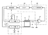
図2に、駆動回路6、検出回路7の構成を詳しく示す。駆動回路6は、それぞれ正弦波発生器からなる基本波発生器12および高調波発生器13を有し、基本波発生器12の出力と高調波発生器13の出力とを重畳して、圧電素子2の対向電極10bに印加するようになっている。基本波発生器12は、電圧V1=Asin(ωt+θ1)を発生し、高調波発生器13は、電圧V2=Bsin(2ωt+θ2)を発生する。基本波発生器12および高調波発生器13は、それぞれ、出力電圧の振幅A,Bおよび位相θ1,θ2を任意に設定可能である。なお、ωは、圧電アクチュエータ5の最適な駆動周波数をfdとすると、ω=1/2πfで表される角速度であり、一定である。
FIG. 2 shows the configuration of the
検出回路7は、検出電極11の充電電流Iを電圧信号に変換するオペアンプからなる電流−電圧変換器14と、電流−電圧変換器14の出力をディジタル信号に変換するA/D変換器15と、このディジタル信号をフーリエ解析するDSP(Digital Signal Processor)16からなる。DSP16は、充電電流Iの基本波成分および高調波成分の振幅および位相をディジタル信号で出力する。
The
本実施形態では、圧電素子2には、基本波発生器12が出力する周波数2πωの電圧成分と、高調波発生器13が出力する周波数4πωの電圧成分としか印加されないので、検出される充電電流Iの基本周波数は、2πωであり、3次以上の高調波は検出されない。
In the present embodiment, only the voltage component of the frequency 2πω output from the
また、検出回路7は、検出電極11の充電電流Iを検出しているが、充電電流Iは、検出電極11の誘導電荷Qを時間微分した値になる。このため、DSP16が出力する充電電流Iの基本波成分と2次高調波成分との比は、誘導電荷Qの基本波成分と2次高調波成分との比の2分の1になる。
Further, the
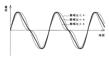
図3に、誘導電荷Qの基本波成分と2次高調波成分との位相差がない場合の振幅比による波形の違いを例示する。誘導電荷Qは、基本波成分の振幅が2次高調波成分の振幅の4倍になるとき、最も理想的な鋸歯状の波形となるが、基本波成分の2次高調波成分に対する振幅比が4より大きくなっても、4より小さくなっても、立ち上がりと立ち下がりの傾きの差が小さくなる。 FIG. 3 illustrates the difference in waveform depending on the amplitude ratio when there is no phase difference between the fundamental wave component and the second harmonic component of the induced charge Q. The induced charge Q has the most ideal sawtooth waveform when the amplitude of the fundamental wave component is four times the amplitude of the second harmonic component, but the amplitude ratio of the fundamental wave component to the second harmonic component is the same. Even if it becomes larger than 4 or smaller than 4, the difference between the rising and falling slopes becomes small.
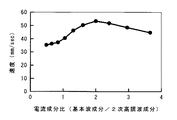
図4に、このような、基本周波数成分と2次高調波成分との比による圧電アクチュエータ5の移動体4の移動速度の変化を示す。このグラフでは、検出回路7が検出する検出電極11の充電電流Iの基本周波数成分と2次高調波成分との比に対する移動体3の移動速度を示しているが、検出電極11の誘導電荷Qの基本周波数成分と2次高調波成分との比は図示する成分比の2倍である。図4に示すように、移動体4の移動速度、つまり、圧電アクチュエータ5の駆動速度は、検出電極11の誘導電荷Qの基本周波数成分の振幅が2次高調波成分の振幅の4倍になるとき最大になる。
FIG. 4 shows a change in the moving speed of the moving body 4 of the piezoelectric actuator 5 depending on the ratio between the fundamental frequency component and the second harmonic component. In this graph, the moving speed of the moving
よって、制御装置8は、DSP16から入力される検出電極11の充電電流Iの基本周波数成分と2次高調波成分との比が2になるように、つまり、検出電極11の誘導電荷Qの変化の基本波成分の振幅と2次高調波成分の振幅との比が4になるように、高調波発生器13の出力電圧の振幅Bの設定値にフィードバックをかける。
Therefore, the
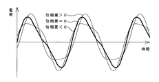
また、図5に、誘導電荷Qの基本波成分と2次高調波成分との振幅比が4である場合の位相差による波形の違いを例示する。誘導電荷Qは、基本波成分と2次高調波成分との位相差が0であるとき、最も理想的な鋸歯状の波形となるが、位相差がプラスになってもマイナスになっても立ち上がりと立ち下がりの傾きの差が小さくなる。 FIG. 5 illustrates the difference in waveform due to the phase difference when the amplitude ratio between the fundamental wave component and the second harmonic component of the induced charge Q is 4. The induced charge Q is the most ideal sawtooth waveform when the phase difference between the fundamental wave component and the second harmonic component is 0, but rises when the phase difference becomes positive or negative. And the difference in the slope of the fall becomes smaller.
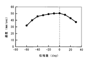
図6に、このような、基本周波数成分と2次高調波成分との位相差による圧電アクチュエータ5の移動体4の移動速度の変化を示す。図示するように、移動体4の移動速度、つまり、圧電アクチュエータ5の駆動速度は、検出電極11の誘導電荷Qの基本周波数成分と2次高調波成分との位相差が0°のときに最大になる。
FIG. 6 shows a change in the moving speed of the moving body 4 of the piezoelectric actuator 5 due to the phase difference between the fundamental frequency component and the second harmonic component. As shown in the figure, the moving speed of the moving body 4, that is, the driving speed of the piezoelectric actuator 5 is maximum when the phase difference between the fundamental frequency component and the second harmonic component of the induced charge Q of the
なお、位相差が±90°以上になると、図5における立ち上がりの傾きと立ち下がりの傾きとの大小が入れ替わり、位相差が180°になると、位相差0°の波形を左右反転した形状になる。つまり、圧電アクチュエータ5の駆動速度は、位相差180°において逆方向の最大値を示す。 When the phase difference becomes ± 90 ° or more, the magnitudes of the rising slope and the falling slope in FIG. 5 are interchanged, and when the phase difference is 180 °, the waveform of the phase difference of 0 ° is reversed left and right. . That is, the driving speed of the piezoelectric actuator 5 shows the maximum value in the reverse direction at a phase difference of 180 °.
よって、制御装置8は、DSP16から入力される基本波成分と2次高調波成分との位相差が駆動方向に応じて、0°または180°のいずれかになるように、高調波発生器13の出力電圧の位相θ2の設定値にフィードバックをかける。
Therefore, the
以上のように、本実施形態の駆動装置1は、高調発生器3の出力する電圧、ひいては、基本波発生器12の出力と重畳された、圧電素子2に印加される駆動電圧の波形を変化させることで、移動体4の移動速度を最大化する。
As described above, the
続いて、図7に、本発明の第2実施形態の駆動装置の回路構成を示す。本実施形態以降の説明においては、第1実施形態と同じ構成要素には同じ符号を付して重複する説明を省略する。本実施形態の駆動回路6は、周波数f1=2πωでデューティ比0.5の矩形波を出力する公知のブリッジ回路である基本波ブリッジ回路17と、周波数f1の倍の周波数f2=4πωでデューティ比0.5の矩形波を出力する公知のブリッジ回路からなる高調波ブリッジ回路18とからなる。
Next, FIG. 7 shows a circuit configuration of a driving apparatus according to the second embodiment of the present invention. In the description after the present embodiment, the same components as those in the first embodiment are denoted by the same reference numerals, and redundant description is omitted. The driving
本実施形態の制御装置8は、基本波ブリッジ回路17および高調波ブリッジ回路18のスイッチング素子のオン/オフを制御する制御信号を出力する。そして、DSP16から入力される基本波成分と2次高調波成分との位相差が駆動方向に応じて、0°または180°のいずれかになるように、基本波ブリッジ回路17を駆動する制御信号と、高調波ブリッジ回路18を駆動する制御信号との位相を変化させる。
The
なお、理想的な矩形波は、2次高調波成分を含まないので、本実施形態のように、基本周波数f1の矩形波と、基本周波数の倍の周波数f2の矩形波とを重畳して印加することで、圧電素子2に印加される駆動電圧の基本波成分と2次高調波成分との位相を独立して調整できる。なお、3次以上の高調波成分も、誘導電荷Qの波形に寄与するが、その構成比が小さいため、基本波成分と2次高調波成分とだけを指標として駆動電圧波形を調整すればよい。
Since an ideal rectangular wave does not include a second harmonic component, a rectangular wave having a fundamental frequency f1 and a rectangular wave having a frequency f2 that is twice the fundamental frequency are applied in a superimposed manner as in the present embodiment. By doing so, the phases of the fundamental wave component and the second harmonic component of the drive voltage applied to the
本実施形態では、誘導電荷Qの基本波成分と2次高調波成分との振幅比を調整することはできないが、誘導電荷Qの基本波成分と2次高調波成分との位相差を調整することで、ある程度駆動効率を改善できる。特に、圧電素子2の弾性などによる振動特性の遅れにバラツキがある場合は、この位相差の調整による駆動効率の改善が有効である。また、基本波ブリッジ回路17および高調波ブリッジ回路18の電源電圧を調整可能とすれば、誘導電荷Qの基本波成分と2次高調波成分との振幅比を調整することも可能になる。
In this embodiment, the amplitude ratio between the fundamental wave component and the second harmonic component of the induced charge Q cannot be adjusted, but the phase difference between the fundamental wave component and the second harmonic component of the induced charge Q is adjusted. Thus, the driving efficiency can be improved to some extent. In particular, when there is variation in the delay of vibration characteristics due to the elasticity of the
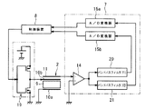
さらに、図8に、本発明の第3実施形態の駆動装置の回路構成を示す。本実施形態の駆動回路6は、1つの公知のブリッジ回路19のみからなる。
Further, FIG. 8 shows a circuit configuration of the driving apparatus according to the third embodiment of the present invention. The
また、本実施形態の検出回路7は、駆動電圧の基本周波数f1=2πωの近傍の周波数帯域のみを通過させる基本波バンドパスフィルタ20と、基本周波数f1の倍の周波数f2=4πωの近傍の周波数帯域のみを通過させる高調波バンドパスフィルタ21とが並列に接続され、それぞれに、電流−電圧変換器14の出力が入力されるようになっている。さらに、検出回路7は、基本波バンドパスフィルタ20を通過した電圧の実行値をディジタル信号に変換するA/D変換器15aと、高調波バンドパスフィルタ21を通過した電圧の実行値をディジタル信号に変換するA/D変換器15bとを有する。つまり、本実施形態の検出回路7は、誘導電荷Qの基本波成分に比例するディジタル値と、誘導電荷Qの2次高調波成分に比例するディジタル値とを制御装置8に入力する。
The
本実施形態では、制御装置8は、ブリッジ回路19のスイッチング素子をオン/オフする周波数f1=2πωの制御信号のデューティ比を、誘導電荷Qの基本波成分の振幅と2次高調波成分の振幅との比が4に近付くように、つまり、充電電流Iの基本周波数成分と2次高調波成分との比が2になるように調整する。
In the present embodiment, the
理想的な矩形波の高調波成分は、デューティ比0.5のときに最大になり、デューティ比が0.5から離れるほど小さくなる。このため、本実施形態のように、駆動電圧のデューティ比を変化させることでも、駆動電圧の基本波成分と2次高調波成分との比を変化させて、アクチュエータ5の駆動効率を改善できる。 The ideal harmonic component of the rectangular wave becomes maximum when the duty ratio is 0.5, and becomes smaller as the duty ratio becomes farther from 0.5. For this reason, the drive efficiency of the actuator 5 can be improved by changing the ratio of the fundamental wave component and the second harmonic component of the drive voltage even by changing the duty ratio of the drive voltage as in the present embodiment.
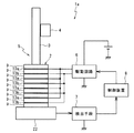
さらに、図9に、本発明の第4実施形態の駆動装置の構成を示す。本実施形態のアクチュエータ5は、圧電素子2の、駆動軸3と反対側の端部に例えばタングステン合金からなる導電性の錘22が固定されている。この錘22は、対向電極10bに圧電層9を介して対向するように配設されており、検出電極を兼ねている。
Further, FIG. 9 shows the configuration of the drive apparatus according to the fourth embodiment of the present invention. In the actuator 5 of this embodiment, a
錘22は、圧電アクチュエータ5の重心を錘22側に位置させ、これによって、圧電素子2の伸縮の中心点を錘22に近づけることで、駆動軸3を安定して振動させるために用いられ、このような錘22の使用は公知である。よって、導電性の錘22を検出電極としても用いることで、検出電極を設けた特殊な圧電素子を用意する必要がなく、コストが削減できる。
The
なお、以上の実施形態では、圧電素子2が1つの検出電極を有する例のみを説明したが、対向電極10a,10bにそれぞれ圧電層9を介して対向する検出電極の誘導電荷量の差分、または、2つの検出電極の間に流れる電流を検出してもよい。
In the above embodiment, only the example in which the
1…駆動装置
2…圧電素子
3…駆動軸
4…移動体
5…圧電アクチュエータ
6…駆動回路
7…検出回路
8…制御装置
9…圧電層
10a,10b…対向電極
11…検出電極
12…基本波発生器
13…高調波発生器
14…電流−電圧変換器
15…A/Dコンバータ
16…DSP
17…基本波ブリッジ回路
18…高調波ブリッジ回路
19…ブリッジ回路
20…基本波バンドパスフィルタ
21…高調波バンドパスフィルタ
22…錘(兼検出電極)
DESCRIPTION OF
DESCRIPTION OF
Claims (9)
前記制御装置は、前記駆動電圧のデューティ比を変化させることを特徴とする請求項1から6のいずれかに記載の駆動装置。 The drive voltage is a rectangular wave having the same frequency as the fundamental frequency of the induced charge,
The drive device according to claim 1, wherein the control device changes a duty ratio of the drive voltage.
Priority Applications (1)
| Application Number | Priority Date | Filing Date | Title |
|---|---|---|---|
| JP2008133253A JP2009284635A (en) | 2008-05-21 | 2008-05-21 | Drive system |
Applications Claiming Priority (1)
| Application Number | Priority Date | Filing Date | Title |
|---|---|---|---|
| JP2008133253A JP2009284635A (en) | 2008-05-21 | 2008-05-21 | Drive system |
Publications (1)
| Publication Number | Publication Date |
|---|---|
| JP2009284635A true JP2009284635A (en) | 2009-12-03 |
Family
ID=41454486
Family Applications (1)
| Application Number | Title | Priority Date | Filing Date |
|---|---|---|---|
| JP2008133253A Pending JP2009284635A (en) | 2008-05-21 | 2008-05-21 | Drive system |
Country Status (1)
| Country | Link |
|---|---|
| JP (1) | JP2009284635A (en) |
Cited By (5)
| Publication number | Priority date | Publication date | Assignee | Title |
|---|---|---|---|---|
| JP2013172512A (en) * | 2012-02-20 | 2013-09-02 | Seiko Epson Corp | Piezoelectric actuator and electronic apparatus |
| CN103346692A (en) * | 2013-07-02 | 2013-10-09 | 南京航空航天大学 | Frequency domain compensation method for piezoelectric actuator hysteresis nonlinearity in vibration active control |
| CN104034249A (en) * | 2014-06-26 | 2014-09-10 | 浙江大学 | Self-alignment area-changing capacitive detection method |
| US9087976B2 (en) | 2010-06-02 | 2015-07-21 | Funai Electric Co., Ltd. | Ultrasonic-motor-driving device and ultrasonic motor unit |
| CN105846712A (en) * | 2016-04-26 | 2016-08-10 | 南京理工大学 | Piezoelectric driving power supply based on inductive charge feedback and control method thereof |
-
2008
- 2008-05-21 JP JP2008133253A patent/JP2009284635A/en active Pending
Cited By (5)
| Publication number | Priority date | Publication date | Assignee | Title |
|---|---|---|---|---|
| US9087976B2 (en) | 2010-06-02 | 2015-07-21 | Funai Electric Co., Ltd. | Ultrasonic-motor-driving device and ultrasonic motor unit |
| JP2013172512A (en) * | 2012-02-20 | 2013-09-02 | Seiko Epson Corp | Piezoelectric actuator and electronic apparatus |
| CN103346692A (en) * | 2013-07-02 | 2013-10-09 | 南京航空航天大学 | Frequency domain compensation method for piezoelectric actuator hysteresis nonlinearity in vibration active control |
| CN104034249A (en) * | 2014-06-26 | 2014-09-10 | 浙江大学 | Self-alignment area-changing capacitive detection method |
| CN105846712A (en) * | 2016-04-26 | 2016-08-10 | 南京理工大学 | Piezoelectric driving power supply based on inductive charge feedback and control method thereof |
Similar Documents
| Publication | Publication Date | Title |
|---|---|---|
| JP6103654B2 (en) | Rectifier circuit having AC-side short-circuit function and synchronous switch harvesting in dielectric converter | |
| US8773004B2 (en) | Circuit for optimizing the recovery of vibratory energy by a mechanical/electrical converter | |
| US10693394B2 (en) | Driving apparatus of vibration-type actuator method of controlling driving vibration-type actuator and image pickup apparatus | |
| US10784041B2 (en) | Electromagnetic power converter | |
| US8552619B2 (en) | Driving circuit for vibration-type actuator | |
| JP5277010B2 (en) | Drive device | |
| JP2009284635A (en) | Drive system | |
| JP5037767B2 (en) | Control device for vibration actuator | |
| US9496481B2 (en) | Controlling device for vibration type actuator | |
| US11728750B2 (en) | Vibration actuator having plural vibrators and inductors | |
| JP2018078769A (en) | Control method for vibration type actuator, vibration type drive device and electronic apparatus | |
| US6448694B2 (en) | Actuator and driving method thereof | |
| JPH10304687A (en) | Driver for oscillatory actuator, and device using oscillatory actuator as drive source | |
| JP5833658B2 (en) | Method and apparatus for electrically exciting an actuator for an ultrasonic motor | |
| JP4110153B2 (en) | Drive device for vibration actuator and drive method for vibration actuator | |
| US6713943B1 (en) | Actuator and driving method thereof | |
| JPS622869A (en) | Supersonic motor drive device | |
| JP6101983B2 (en) | Power generation circuit and transmitter using the same | |
| JP5930152B2 (en) | POWER GENERATION DEVICE, ELECTRONIC DEVICE, MOBILE DEVICE, AND METHOD FOR CONTROLLING POWER GENERATION DEVICE | |
| JP5153170B2 (en) | Ultrasonic motor drive apparatus and method | |
| US20130063054A1 (en) | Driving apparatus for vibration-type actuator | |
| JP5972026B2 (en) | Vibration detection device and control device for vibration actuator | |
| US11588417B2 (en) | Vibration actuator and driving device for vibration actuator | |
| JPS61224879A (en) | Drive circuit of surface wave motor | |
| JP2010263672A (en) | Vibration type drive device and method of controlling the same |