JP2009283159A - Induction heat generating roller device - Google Patents
Induction heat generating roller device Download PDFInfo
- Publication number
- JP2009283159A JP2009283159A JP2008131492A JP2008131492A JP2009283159A JP 2009283159 A JP2009283159 A JP 2009283159A JP 2008131492 A JP2008131492 A JP 2008131492A JP 2008131492 A JP2008131492 A JP 2008131492A JP 2009283159 A JP2009283159 A JP 2009283159A
- Authority
- JP
- Japan
- Prior art keywords
- roller body
- fluid flow
- roller
- fluid passage
- flow holes
- Prior art date
- Legal status (The legal status is an assumption and is not a legal conclusion. Google has not performed a legal analysis and makes no representation as to the accuracy of the status listed.)
- Granted
Links
- 230000006698 induction Effects 0.000 title claims abstract description 28
- 239000012530 fluid Substances 0.000 claims abstract description 63
- 230000004907 flux Effects 0.000 claims abstract description 6
- 239000012809 cooling fluid Substances 0.000 claims abstract description 4
- 238000010438 heat treatment Methods 0.000 claims description 12
- WYTGDNHDOZPMIW-RCBQFDQVSA-N alstonine Natural products C1=CC2=C3C=CC=CC3=NC2=C2N1C[C@H]1[C@H](C)OC=C(C(=O)OC)[C@H]1C2 WYTGDNHDOZPMIW-RCBQFDQVSA-N 0.000 claims description 2
- 239000007788 liquid Substances 0.000 claims description 2
- 230000002093 peripheral effect Effects 0.000 abstract 2
- 239000011796 hollow space material Substances 0.000 abstract 1
- XEEYBQQBJWHFJM-UHFFFAOYSA-N Iron Chemical group [Fe] XEEYBQQBJWHFJM-UHFFFAOYSA-N 0.000 description 3
- 239000000463 material Substances 0.000 description 3
- 239000002184 metal Substances 0.000 description 3
- 229910052751 metal Inorganic materials 0.000 description 3
- WABPQHHGFIMREM-UHFFFAOYSA-N lead(0) Chemical compound [Pb] WABPQHHGFIMREM-UHFFFAOYSA-N 0.000 description 2
- 230000001939 inductive effect Effects 0.000 description 1
- 239000007791 liquid phase Substances 0.000 description 1
- 239000012071 phase Substances 0.000 description 1
- 239000011347 resin Substances 0.000 description 1
- 229920005989 resin Polymers 0.000 description 1
Images


Abstract
Description
本発明は、ローラ本体に流体通流孔を形成した誘導発熱ローラ装置に関するものである。 The present invention relates to an induction heating roller device in which a fluid flow hole is formed in a roller body.
樹脂フィルムなどの処理物をローラ本体に当接して通過させる間に処理物を所定の温度に加熱する手段として誘導発熱ローラを使用する場合がある。この場合、誘導発熱ローラは処理物を所定の温度に高めるためには適切であるが、高温の処理物から奪熱して所定の温度にまで急速に低下させることはできない。そこで、誘導発熱ローラにおいてもこの奪熱が行えるように、ローラ本体に流体(熱媒体)を通流する流体通流路を形成し、ローラ本体が必要以上に加熱された場合に、この流体通流路に冷却流体を通流してローラ本体を冷却し、これによりローラ本体を所定の温度に調整することが考えられている。 In some cases, an induction heating roller is used as means for heating the processed material to a predetermined temperature while the processed material such as a resin film is in contact with the roller body and is passed therethrough. In this case, the induction heating roller is suitable for raising the processed object to a predetermined temperature, but cannot remove the heat from the high-temperature processed object and rapidly decrease to the predetermined temperature. Therefore, a fluid flow path through which a fluid (heat medium) flows is formed in the roller body so that the induction heat roller can also perform this heat removal. It has been considered to cool the roller body by passing a cooling fluid through the flow path, thereby adjusting the roller body to a predetermined temperature.
ローラ本体に流体通流路を形成する手段として、ローラ本体の肉厚内に一本の螺旋状の熱媒体通流孔を形成するものがある。このような一本の螺旋状の熱媒体通流孔は、その孔径を小さくしピッチ(螺旋孔間隔)を狭くしている。これによりローラ本体の肉厚内を通流する熱媒体とローラの接触面を広くすることができ、ローラ本体との熱交換効率を高めることができる。
しかし、このような螺旋孔では、ローラ本体の大型化にともないローラ本体の端部から端部に至る距離が長くなり、また、螺旋孔の径が小さいことと相俟って、ヘッドロス(圧損)が大きく、流体供給力を高める必要がある。また、出入り口の温度勾配が大きく、ローラ本体の出入り口間で膨張差が発生し円筒プロファイルが劣るといった問題があった。 However, in such a spiral hole, the distance from the end of the roller body to the end increases as the size of the roller body increases, and coupled with the fact that the diameter of the spiral hole is small, head loss (pressure loss) The fluid supply capacity must be increased. In addition, there is a problem that the temperature gradient at the entrance / exit is large, a difference in expansion occurs between the entrance / exit of the roller body, and the cylindrical profile is inferior.
本発明が解決しようとする課題は、ローラ本体との熱交換効率を低減することなく、ローラ本体の肉厚内に形成した流体通流孔のヘッドロスを低減するとともに、ローラ本体の円筒プロファイルを良好に維持することができるようにし、斯かる問題を解消する点にある。 The problem to be solved by the present invention is to reduce the head loss of the fluid flow hole formed in the wall thickness of the roller body without reducing the heat exchange efficiency with the roller body, and to improve the cylindrical profile of the roller body. Therefore, it is possible to maintain such a problem and to solve such a problem.
本発明は、円筒状のローラ本体と、前記ローラ本体の中空内に配置された誘導コイルを有する磁束発生機構とを備え、前記誘導コイルに交流電流を通電することにより前記ローラ本体を発熱してなる誘導発熱ローラ装置において、前記ローラ本体の軸方向の両側端部の肉厚内に、該ローラ本体の周方向に沿う環状の流体通流孔を形成するとともに、前記両側の環状の流体通流孔に連通する蛇行状または螺旋状の流体通流孔を該ローラ本体の周方向に複数形成し、前記環状の流体通流孔および前記複数の流体通流孔に冷却流体を通流して前記ローラ本体の温度を調整してなることを主な特徴とする。 The present invention comprises a cylindrical roller body and a magnetic flux generating mechanism having an induction coil disposed in the hollow of the roller body, and heats the roller body by supplying an alternating current to the induction coil. In the induction heating roller device, the annular fluid flow holes along the circumferential direction of the roller body are formed in the wall thickness at both end portions in the axial direction of the roller body, and the annular fluid flow paths on the both sides are formed. A plurality of meandering or spiral fluid flow holes communicating with the holes are formed in the circumferential direction of the roller body, and the cooling fluid is passed through the annular fluid flow holes and the plurality of fluid flow holes. The main feature is that the temperature of the main body is adjusted.
本発明では、両側の環状の流体通流孔に連通する蛇行状または螺旋状の流体通流孔を該ローラ本体の周方向に複数形成しているので、1本の流体通流孔の延べ距離が短くなり、流体通流孔によるヘッドロスを低減することができるとともに、流体通流孔の出入り口の温度勾配が小さく、ローラ本体の円筒プロファイルも良好になる。また、流体通流孔を蛇行状または螺旋状にしているので、流体とローラの接触面を広くすることができ、処理物との高い熱交換効率を維持することができる。 In the present invention, since a plurality of meandering or spiral fluid flow holes communicating with the annular fluid flow holes on both sides are formed in the circumferential direction of the roller body, the total distance of one fluid flow hole The head loss due to the fluid flow hole can be reduced, the temperature gradient at the entrance and exit of the fluid flow hole is small, and the cylindrical profile of the roller body is also good. Moreover, since the fluid flow hole is meandering or spiraling, the contact surface between the fluid and the roller can be widened, and high heat exchange efficiency with the processed product can be maintained.
ローラ本体との熱交換効率を低減することなく、ローラ本体の肉厚内に形成した流体通流孔のヘッドロスを低減するとともに、ローラ本体の円筒プロファイルを良好に維持することができるようにする目的を、ローラ本体の軸方向の両側端部の肉厚内に、ローラ本体の周方向に沿う環状の流体通流孔を形成するとともに、その両側の環状の流体通流孔に連通する流体通流孔を蛇行状または螺旋状にし、これをローラ本体の周方向に複数形成することにより実現した。 The purpose is to reduce the head loss of the fluid flow hole formed in the wall thickness of the roller body without reducing the efficiency of heat exchange with the roller body and to maintain the cylindrical profile of the roller body well. Is formed in the wall thickness at both end portions in the axial direction of the roller body, and an annular fluid flow hole is formed along the circumferential direction of the roller body, and the fluid flow is communicated with the annular fluid flow holes on both sides. This was realized by making the holes meandering or spiraling and forming a plurality of holes in the circumferential direction of the roller body.
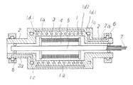
図1は、本発明の実施例に係る誘導発熱ローラ装置の断面図、図2は図1に示す誘導発熱ローラ装置のローラ本体の展開平面図である。図1および図2において、1はローラ本体、2はローラ本体の端部に固定したジャーナル、3は誘導コイル、4は鉄心、5は支持ロッド、6はロータリジョイント、7は誘導コイルの引出し導線である。鉄心4に巻装した誘導コイル3からなる磁束発生機構は、支持ロッド5に保持され、ローラ本体1の中空内に配置されている。支持ロッド5は、両側のジャーナル2内で回転軸受けを介してジャーナルに支持されており、図示しない回り止めで回転不能に固定されている。
FIG. 1 is a sectional view of an induction heat roller device according to an embodiment of the present invention, and FIG. 2 is a developed plan view of a roller body of the induction heat roller device shown in FIG. 1 and 2, 1 is a roller body, 2 is a journal fixed to the end of the roller body, 3 is an induction coil, 4 is an iron core, 5 is a support rod, 6 is a rotary joint, and 7 is a lead wire for the induction coil. It is. A magnetic flux generation mechanism including the
誘導コイル3に引出し導線7を経て交流電圧が印加されると交番磁束が発生し、その交番磁束はローラ本体1を通過し、これによりローラ本体1に誘導電流が誘起してローラ本体1はその誘起電流でジュール発熱して加熱される。この加熱は、誘導コイル3の中央部で大きく端部に至るほど小さくなり、ローラ本体1の軸方向に加熱斑が発生する。この加熱斑を防止するためにローラ本体1の外表面近傍の肉厚内に軸方向に伸びるジャケット室1aを設け、このジャケット室1aに気液二相の熱媒体を封入している。ジャケット室1aの液相の熱媒体は高温部で熱を奪って気化し、その気体は低温部に移動して熱を放出して液化する。即ち潜熱移動する。この潜熱移動によりローラ本体1の軸方向の処理物が当接する外側表面の温度を均一化することができる。なお、ジャケット室1aは、ローラ本体1にドリルなどによって軸方向に伸びる孔を周方向に複数形成し、その複数の各孔の両端を閉塞して1孔ごと独立に形成する場合も、また、複数のうちの所定数または全部の各孔の端部または中間部または端部と中間部で連通させて形成する場合もある。
When an alternating voltage is applied to the
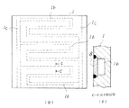
ローラ本体1には、高温から所定の温度にまで低下させるなどのローラ本体1の温度を調整するために、図2(a)に示すようにローラ本体1の軸方向の両側端部の肉厚内に、ローラ本体1の周方向に沿う環状の流体通流孔1cを形成し、この両側の環状の流体通流孔1cに連通する蛇行状の流体通流孔1bが形成されている。このようなローラ本体1は、平板状の非磁性金属板に環状の流体通流孔1cおよび蛇行状の流体通流孔1bとなる凹溝を形成し、その凹溝の開口部を図2(b)に示すように、金属板8で覆い、これを円筒状に成形して作製される。
In order to adjust the temperature of the roller body 1 such that the roller body 1 is lowered from a high temperature to a predetermined temperature, as shown in FIG. An annular
そして、ローラ本体1の軸方向の両側端部の肉厚内に形成した一方の環状の流体通流孔1cと一方のロータリジョイント6に連通する一方のジャーナル2内の通流孔2aと連通させ、また、ローラ本体1の軸方向の両側端部の肉厚内に形成した他方の環状の流体通流孔1cと他方のロータリジョイント6に連通する他方のジャーナル2内の通流孔2aと連通させる。すなわち、一方のロータリジョイント6から供給した熱媒体となる流体は、ジャーナル2内の通流孔2aを経由して一方の環状の流体通流孔1cに送られ、複数の各蛇行状の流体通流孔1bを経由し、他方の環状の流体通流孔1cに送られ、他方のジャーナル2内の通流孔2aを経由して他方のロータリジョイントから排出される。
Then, one annular
図3は、本発明の他の実施例に係る誘導発熱ローラ装置の断面図、図4は図3に示す誘導発熱ローラ装置のローラ本体の展開平面図である。なお、図1に示す実施例と同一部分には同一の符号を付し、その部分の説明は省略する。図1に示す実施例と異なる部分は、ローラ本体1の軸方向の両側端部の肉厚内に形成した環状の流体通流孔1cと連通する複数の流体通流孔1d1〜1d3をそれぞれ螺旋状に形成した点である。
FIG. 3 is a sectional view of an induction heat roller apparatus according to another embodiment of the present invention, and FIG. 4 is a developed plan view of a roller body of the induction heat roller apparatus shown in FIG. In addition, the same code | symbol is attached | subjected to the same part as the Example shown in FIG. 1, and description of the part is abbreviate | omitted. 1 differs from the embodiment shown in FIG. 1 in that a plurality of fluid flow holes 1d1 to 1d3 communicating with annular
このようなローラ本体1は、図4に示すように平板状の金属板の両側の端部に環状の流体通流孔1cとなる孔1cをドリルなどで形成し、その孔1cに対して傾斜する所定の間隔を隔てた複数の孔1d1〜1d3、孔1cと交差するときにはその孔1cを終点とする孔をドリルなどで形成し、これを円筒状に成形して作製される。この円筒状に成形するに際し、孔1d1、1d2、1d3はそれぞれ連通して、一端が一方の環状の流体通流孔1cに連通し、他端が他方の環状の流体通流孔1cに連通する3本の螺旋状の流体通流孔1d1〜1d3が形成される。
As shown in FIG. 4, such a roller body 1 is formed with
そして、ローラ本体1の軸方向の両側端部の肉厚内に形成した一方の環状の流体通流孔1cと一方のロータリジョイント6に連通する一方のジャーナル2内の通流孔2aと連通させ、また、ローラ本体1の軸方向の両側端部の肉厚内に形成した他方の環状の流体通流孔1cと他方のロータリジョイント6に連通する他方のジャーナル2内の通流孔2aと連通させる。すなわち、一方のロータリジョイント6から供給した流体は、ジャーナル2内の通流孔2aを経由して一方の環状の流体通流孔1cに送られ、複数の各螺旋状の流体通流孔1d1、1d2、1d3を経由し、他方の環状の流体通流孔1cに送られ、他方のジャーナル2内の通流孔2aを経由して他方のロータリジョイントから排出される。
Then, one annular
以上、いずれの実施例においても、流体通流孔径をたとえば10mm程度と小さくし、また、間隔を20mm程度と狭くし、これによりローラ本体の肉厚内を通流する流体とローラの接触面を広くすることができ、ローラ本体との熱交換効率を高めることができる。また、実施例では流体通流孔を3本としているが、流体通流孔の本数は任意である。 As described above, in any of the embodiments, the diameter of the fluid flow hole is reduced to, for example, about 10 mm, and the interval is reduced to about 20 mm, so that the contact surface between the fluid flowing through the thickness of the roller body and the roller can be provided. The heat exchange efficiency with the roller body can be increased. In the embodiment, the number of fluid flow holes is three, but the number of fluid flow holes is arbitrary.
1 ローラ本体
1a ジャケット
1b 蛇行状の流体通流孔
1c 環状の流体通流孔
1d1、1d2、1d3 螺旋状の流体通流孔
2 ジャーナル
3 誘導コイル
4 鉄心
5 支持ロッド
6 ロータリジョイント
DESCRIPTION OF SYMBOLS 1 Roller body 1a Jacket 1b Serpentine
Claims (2)
Priority Applications (1)
| Application Number | Priority Date | Filing Date | Title |
|---|---|---|---|
| JP2008131492A JP5196549B2 (en) | 2008-05-20 | 2008-05-20 | Induction heating roller device |
Applications Claiming Priority (1)
| Application Number | Priority Date | Filing Date | Title |
|---|---|---|---|
| JP2008131492A JP5196549B2 (en) | 2008-05-20 | 2008-05-20 | Induction heating roller device |
Publications (2)
| Publication Number | Publication Date |
|---|---|
| JP2009283159A true JP2009283159A (en) | 2009-12-03 |
| JP5196549B2 JP5196549B2 (en) | 2013-05-15 |
Family
ID=41453425
Family Applications (1)
| Application Number | Title | Priority Date | Filing Date |
|---|---|---|---|
| JP2008131492A Active JP5196549B2 (en) | 2008-05-20 | 2008-05-20 | Induction heating roller device |
Country Status (1)
| Country | Link |
|---|---|
| JP (1) | JP5196549B2 (en) |
Cited By (4)
| Publication number | Priority date | Publication date | Assignee | Title |
|---|---|---|---|---|
| JP2015135231A (en) * | 2013-12-20 | 2015-07-27 | トクデン株式会社 | Overheat steam generating device |
| CN109041309A (en) * | 2018-10-12 | 2018-12-18 | 威海达明新材料科技有限公司 | Composite electromagnetic induction heating device |
| CN109140539A (en) * | 2017-06-15 | 2019-01-04 | 佛山市顺德区美的电热电器制造有限公司 | Coil bracket, coil panel and electromagnetism cooker |
| US10510480B2 (en) | 2013-12-20 | 2019-12-17 | Tokuden Co., Ltd. | Power circuit, iron core for Scott connected transformer, Scott connected transformer, and superheated steam generator |
Citations (3)
| Publication number | Priority date | Publication date | Assignee | Title |
|---|---|---|---|---|
| JPH10502726A (en) * | 1995-05-09 | 1998-03-10 | エデュアルド・キュスターズ・マシーネンファブリーク・ゲーエムベーハー・ウント・コンパニー・カーゲー | Heatable roll |
| JP2004116538A (en) * | 2002-09-24 | 2004-04-15 | Tokuden Co Ltd | Heat media flowing roller |
| JP2007093009A (en) * | 2006-10-23 | 2007-04-12 | Tokuden Co Ltd | Induction heat generating roller device |
-
2008
- 2008-05-20 JP JP2008131492A patent/JP5196549B2/en active Active
Patent Citations (3)
| Publication number | Priority date | Publication date | Assignee | Title |
|---|---|---|---|---|
| JPH10502726A (en) * | 1995-05-09 | 1998-03-10 | エデュアルド・キュスターズ・マシーネンファブリーク・ゲーエムベーハー・ウント・コンパニー・カーゲー | Heatable roll |
| JP2004116538A (en) * | 2002-09-24 | 2004-04-15 | Tokuden Co Ltd | Heat media flowing roller |
| JP2007093009A (en) * | 2006-10-23 | 2007-04-12 | Tokuden Co Ltd | Induction heat generating roller device |
Cited By (8)
| Publication number | Priority date | Publication date | Assignee | Title |
|---|---|---|---|---|
| JP2015135231A (en) * | 2013-12-20 | 2015-07-27 | トクデン株式会社 | Overheat steam generating device |
| US10510480B2 (en) | 2013-12-20 | 2019-12-17 | Tokuden Co., Ltd. | Power circuit, iron core for Scott connected transformer, Scott connected transformer, and superheated steam generator |
| US10650962B2 (en) | 2013-12-20 | 2020-05-12 | Tokuden Co., Ltd. | Power circuit, iron core for Scott connected transformer, Scott connected transformer, and superheated steam generator |
| US10840011B2 (en) | 2013-12-20 | 2020-11-17 | Tokuden Co., Ltd. | Power circuit, iron core for scott connected transformer, scott connected transformer, and superheated steam generator |
| US10978243B2 (en) | 2013-12-20 | 2021-04-13 | Tokuden Co., Ltd. | Power circuit, iron core for Scott connected transformer, Scott connected transformer, and superheated steam generator |
| CN109140539A (en) * | 2017-06-15 | 2019-01-04 | 佛山市顺德区美的电热电器制造有限公司 | Coil bracket, coil panel and electromagnetism cooker |
| CN109140539B (en) * | 2017-06-15 | 2020-09-01 | 佛山市顺德区美的电热电器制造有限公司 | Coil panel support, coil panel and electromagnetic cooking device |
| CN109041309A (en) * | 2018-10-12 | 2018-12-18 | 威海达明新材料科技有限公司 | Composite electromagnetic induction heating device |
Also Published As
| Publication number | Publication date |
|---|---|
| JP5196549B2 (en) | 2013-05-15 |
Similar Documents
| Publication | Publication Date | Title |
|---|---|---|
| KR101314038B1 (en) | Fluid heating device and heating medium passing roller device using the same | |
| JP5196549B2 (en) | Induction heating roller device | |
| JP4958679B2 (en) | Fluid heating device | |
| JPH10125458A (en) | Inductive heating roller device | |
| JP2012088044A (en) | Fluid heating device | |
| JP2009041885A (en) | Fluid heating device | |
| JP4963042B2 (en) | Heat transfer roller | |
| JP2008082700A (en) | Superheated steam generator | |
| JP4716705B2 (en) | Heat treatment roller | |
| JP2006207825A (en) | Heat medium conduction roller | |
| KR101137528B1 (en) | Cartridge-type inline heater and system for controlling working fluid temperature using the same | |
| JP3893919B2 (en) | Induction heating unit for fluid heating | |
| JP2007256988A (en) | Fixing device and image forming apparatus | |
| JP2005222781A (en) | Fluid substance heating device using induction heating | |
| JP4885190B2 (en) | High frequency induction heating device | |
| EP3934381B1 (en) | Induction heated roll apparatus | |
| JP2005098553A (en) | Heat exchanger | |
| JP2007294207A (en) | High-frequency induction heating apparatus and its heating method | |
| JP7296111B2 (en) | Heat Roller Device, Method for Manufacturing Heat Roller Device, and Method for Adjusting Cooling Capacity of Heat Roller Device | |
| JP3743064B2 (en) | Heating device | |
| JP2018051848A (en) | Heat medium flowing roller apparatus | |
| JP2006071180A (en) | Superheated steam generator | |
| JP2005243402A (en) | Induction exothermic roller device | |
| JP2007168223A (en) | Fluid heating device and heat medium circulation roller device using the device | |
| JP2012022934A (en) | Induction heating apparatus and double tube for the same |
Legal Events
| Date | Code | Title | Description |
|---|---|---|---|
| A621 | Written request for application examination |
Free format text: JAPANESE INTERMEDIATE CODE: A621 Effective date: 20110210 |
|
| A977 | Report on retrieval |
Free format text: JAPANESE INTERMEDIATE CODE: A971007 Effective date: 20120910 |
|
| A131 | Notification of reasons for refusal |
Free format text: JAPANESE INTERMEDIATE CODE: A131 Effective date: 20120918 |
|
| A521 | Request for written amendment filed |
Free format text: JAPANESE INTERMEDIATE CODE: A523 Effective date: 20121030 |
|
| TRDD | Decision of grant or rejection written | ||
| A01 | Written decision to grant a patent or to grant a registration (utility model) |
Free format text: JAPANESE INTERMEDIATE CODE: A01 Effective date: 20130201 |
|
| A61 | First payment of annual fees (during grant procedure) |
Free format text: JAPANESE INTERMEDIATE CODE: A61 Effective date: 20130201 |
|
| FPAY | Renewal fee payment (event date is renewal date of database) |
Free format text: PAYMENT UNTIL: 20160215 Year of fee payment: 3 |
|
| R150 | Certificate of patent or registration of utility model |
Ref document number: 5196549 Country of ref document: JP Free format text: JAPANESE INTERMEDIATE CODE: R150 Free format text: JAPANESE INTERMEDIATE CODE: R150 |
|
| R250 | Receipt of annual fees |
Free format text: JAPANESE INTERMEDIATE CODE: R250 |
|
| R250 | Receipt of annual fees |
Free format text: JAPANESE INTERMEDIATE CODE: R250 |
|
| R250 | Receipt of annual fees |
Free format text: JAPANESE INTERMEDIATE CODE: R250 |
|
| R250 | Receipt of annual fees |
Free format text: JAPANESE INTERMEDIATE CODE: R250 |
|
| R250 | Receipt of annual fees |
Free format text: JAPANESE INTERMEDIATE CODE: R250 |
|
| R250 | Receipt of annual fees |
Free format text: JAPANESE INTERMEDIATE CODE: R250 |
|
| R250 | Receipt of annual fees |
Free format text: JAPANESE INTERMEDIATE CODE: R250 |
|
| R250 | Receipt of annual fees |
Free format text: JAPANESE INTERMEDIATE CODE: R250 |
|
| R250 | Receipt of annual fees |
Free format text: JAPANESE INTERMEDIATE CODE: R250 |