JP2009278528A - Dll circuit, and semiconductor device - Google Patents
Dll circuit, and semiconductor device Download PDFInfo
- Publication number
- JP2009278528A JP2009278528A JP2008129638A JP2008129638A JP2009278528A JP 2009278528 A JP2009278528 A JP 2009278528A JP 2008129638 A JP2008129638 A JP 2008129638A JP 2008129638 A JP2008129638 A JP 2008129638A JP 2009278528 A JP2009278528 A JP 2009278528A
- Authority
- JP
- Japan
- Prior art keywords
- circuit
- dll
- clock
- signal
- duty
- Prior art date
- Legal status (The legal status is an assumption and is not a legal conclusion. Google has not performed a legal analysis and makes no representation as to the accuracy of the status listed.)
- Ceased
Links
Images


Classifications
-
- H—ELECTRICITY
- H03—ELECTRONIC CIRCUITRY
- H03L—AUTOMATIC CONTROL, STARTING, SYNCHRONISATION, OR STABILISATION OF GENERATORS OF ELECTRONIC OSCILLATIONS OR PULSES
- H03L7/00—Automatic control of frequency or phase; Synchronisation
- H03L7/06—Automatic control of frequency or phase; Synchronisation using a reference signal applied to a frequency- or phase-locked loop
- H03L7/08—Details of the phase-locked loop
- H03L7/081—Details of the phase-locked loop provided with an additional controlled phase shifter
- H03L7/0812—Details of the phase-locked loop provided with an additional controlled phase shifter and where no voltage or current controlled oscillator is used
- H03L7/0814—Details of the phase-locked loop provided with an additional controlled phase shifter and where no voltage or current controlled oscillator is used the phase shifting device being digitally controlled
Landscapes
- Dram (AREA)
- Pulse Circuits (AREA)
- Manipulation Of Pulses (AREA)
- Stabilization Of Oscillater, Synchronisation, Frequency Synthesizers (AREA)
Abstract
Description
本発明は半導体装置のDLL(Delay-Locked Loop)回路に関し、特にDLL回路の出力クロックとなるDLLクロックをモニタ(監視)し、DLLクロックのクロッキング動作の有無を検出した結果をDLL回路におけるロック制御に使用することで、周波数の高い入力クロックを短サイクルでロックすることが可能となる、DLL回路及びこれを備える半導体装置に関する。 The present invention relates to a DLL (Delay-Locked Loop) circuit of a semiconductor device, and in particular, monitors a DLL clock serving as an output clock of the DLL circuit, and detects the result of detecting the presence or absence of a clocking operation of the DLL clock. The present invention relates to a DLL circuit that can lock an input clock having a high frequency in a short cycle when used for control, and a semiconductor device including the DLL circuit.
最近の電子システムは高速化され、システムを構成する半導体装置間のデータ転送速度は非常に高速化されている。そのため半導体装置においても高速データ転送動作が求められ、半導体装置内部ではクロックに同期させたクロック同期方式が採用されている。例えば半導体記憶装置としては、シンクロナスDRAM( Synchronous Dynamic Random Access Memory、以下SDRAMと略記する)がある。さらにSDRAMを進化させ、クロックの立ち上がり/立ち下がりエッジに同期させたDDR(Double Data Rate)、DDR2及びDDR3方式のSDRAMが開発されている。 Recent electronic systems have been increased in speed, and the data transfer speed between semiconductor devices constituting the system has been greatly increased. For this reason, a high-speed data transfer operation is also required in a semiconductor device, and a clock synchronization method synchronized with a clock is adopted inside the semiconductor device. For example, as a semiconductor memory device, there is a synchronous DRAM (Synchronous Dynamic Random Access Memory, hereinafter abbreviated as SDRAM). Furthermore, DDR (Double Data Rate), DDR2 and DDR3 SDRAMs have been developed by further evolving SDRAM and synchronizing with rising / falling edges of a clock.
これらのSDRAMにおいては、クロックに同期させるためにDLL回路が採用され、内部クロックと外部クロックとのタイミングを同期させている。 In these SDRAMs, a DLL circuit is employed to synchronize with the clock, and the timings of the internal clock and the external clock are synchronized.
図9に、従来型のDLL回路を示す。図9において、外部から入力されるクロック信号CK、/CK(‘/CK’は外部クロック信号CKの論理反転信号)は、初段回路11を通過後にデューティ調整、遅延調整行いDLLクロックとして出力される。
FIG. 9 shows a conventional DLL circuit. In FIG. 9, clock signals CK and / CK ('/ CK' are logically inverted signals of the external clock signal CK) input from the outside pass through the
ここでDLLクロックは図9の点線(a)のパスで示すようにDQレプリカ回路15にも入力され、DQレプリカ出力とクロック信号CK、/CKとの位相比較が位相検知回路16により行なわれ、位相判定結果が遅延制御回路13にフィードバックされる。遅延制御回路13は、位相検知回路16から入力した位相判定結果の信号を基に、遅延回路12への遅延信号を生成し、遅延回路12内の遅延素子の調整を行う。
Here, the DLL clock is also input to the
また、図9の点線(b)で示すパスにおいてはDLLクロックはデューティ検知回路21へ入力され、デューティの判定(例えば、50%以上または以下)が行なわれ、デューティ判定結果はデューティ制御回路22へフィードバックされる。デューティ制御回路22は、デューティ検知回路21から入力したデューティ判定結果の信号を基に、デューティ調整回路23への制御信号(デューティ信号)を生成する。デューティ調整回路23は。デューティ制御回路22から出力されるデューティ信号に従い、クロック信号のデューティ調整を行なう。
In the path indicated by the dotted line (b) in FIG. 9, the DLL clock is input to the
この場合に、遅延回路12では、DQレプリカ回路15の出力とクロック信号CK、/CKのタイミングスキューを無くすように遅延量の調整が行われ、また、デューティ調整回路23により、DLLクロックのデューティが50%または50%に近い値となるようにデューティ調整が行われる。
In this case, the
また、初段回路11から出力されるクロック信号は、カウンタクロック生成回路17により分周されてカウンタクロックとしてDLLサイクルカウンタ18に入力される。DLLサイクルカウンタ18は、入力したカウンタクロックを基に、所定の周期ごとに更新クロックを生成して、遅延制御回路13及びデューティ制御回路22に向けて出力する。
The clock signal output from the
遅延制御回路13及びデューティ制御回路22では、DLLサイクルカウンタ18から出力される更新クロックによって更新動作を行なう。
In the
ところで、上述したDLL回路においては、DLLリセット期間中には短サイクル数でロック制御(遅延量およびデューティを調整して外部クロックと内部クロックの同期を取る制御)を行う必要があるため遅延調整もしくはデューティ調整を同時に実施している。この際、入力クロックの周波数が高い場合には入力クロックのパルス幅に対して調整による遅延量の変動が大きくなりロック制御過程において、DLLクロックのパルスが消失する期間が発生することがある。 By the way, in the DLL circuit described above, it is necessary to perform lock control (control to synchronize the external clock and the internal clock by adjusting the delay amount and duty) during the DLL reset period. Duty adjustment is performed at the same time. At this time, when the frequency of the input clock is high, the fluctuation of the delay amount due to the adjustment becomes large with respect to the pulse width of the input clock, and a period during which the DLL clock pulse disappears may occur in the lock control process.
この場合に位相検知回路16もしくはデューティ検知回路21はDLLクロックをトリガとして実施するため、DLLクロックが消失した場合は正確な位相検知を実施することができないという問題が生じる。
In this case, since the
また、デューティ検知、および位相検知において誤判定を繰り返すとロックに要するサイクル数が増大するばかりではなく所定のスペック内でロックすることが出来なくなるという問題も生じる。従って、このDLLクロックの消失により発生する問題の解決が望まれていた。 Further, if erroneous determination is repeated in duty detection and phase detection, not only will the number of cycles required for locking increase, but there will also be a problem that it is impossible to lock within predetermined specifications. Therefore, it has been desired to solve the problem caused by the disappearance of the DLL clock.
なお、従来技術のクロック生成回路がある(例えば、特許文献1を参照)。この特許文献1のクロック生成回路は、簡易な回路を付加するだけで、位相制御で問題となる出力クロックのデューティのずれを回避し、より高精度の位相制御を行なえるクロック生成回路を実現することを目的としている。このために、可変遅延回路の後段にクロックのデューティ調整回路を設け、クロックの立ち上がりエッジで可変遅延回路の遅延量を制御し、立ち上がりエッジの位相が基準となるクロックと一致した段階で、立ち下がりエッジによってデューティ調整回路により信号のパルス幅を調整することによって、出力クロックのデューティを基準となるクロックのデューティと一致させるようにしている。 Note that there is a conventional clock generation circuit (see, for example, Patent Document 1). The clock generation circuit disclosed in Patent Document 1 realizes a clock generation circuit that can avoid a duty shift of the output clock, which is a problem in phase control, and can perform more accurate phase control by simply adding a simple circuit. The purpose is that. For this purpose, a clock duty adjustment circuit is provided after the variable delay circuit, the delay amount of the variable delay circuit is controlled by the rising edge of the clock, and the falling edge is set when the phase of the rising edge coincides with the reference clock. By adjusting the pulse width of the signal by the duty adjustment circuit according to the edge, the duty of the output clock is made to coincide with the duty of the reference clock.
しかしながら、特許文献1のクロック生成回路は、DLL回路のロック制御において、上述したDLLクロックが消失した場合に誤判定により正確な位相調整等ができなくなり、ロックに要するサイクル数が増大するという問題を解決しようとするものではなく、本願とは、発明の目的と構成が異なるものである。
上述したように、従来の半導体装置のDLL回路においては、DLLリセット期間中には短サイクル数でロック制御を行う必要があるため遅延調整もしくはデューティ調整を同時に実施している。この際、入力クロックの周波数が高い場合には入力クロックのパルス幅に対して調整による遅延量の変動が大きくなりロック制御の過程において、DLLクロックのパルスが消失する期間が発生し、正確な位相検知およびデューティ検知を実施することができないという問題が生じていた。 As described above, in the DLL circuit of the conventional semiconductor device, since it is necessary to perform lock control with the short cycle number during the DLL reset period, delay adjustment or duty adjustment is performed simultaneously. At this time, when the frequency of the input clock is high, the fluctuation of the delay amount due to the adjustment becomes large with respect to the pulse width of the input clock, and a period during which the pulse of the DLL clock disappears occurs in the lock control process. There has been a problem that detection and duty detection cannot be performed.
また、デューティ検知、および位相検知において誤判定を繰り返すとロックに要するサイクル数が増大するばかりではなく所定のスペック内でロックすることが出来なくなるという問題があった。 In addition, if erroneous determination is repeated in duty detection and phase detection, there is a problem that not only the number of cycles required for locking increases, but also locking cannot be performed within a predetermined specification.
本発明は、斯かる実情に鑑みなされたものであり、本発明の目的は、DLL回路の遅延量制御およびデューティ制御を実施するロック制御において、DLLクロックが消失した場合に、位相検知およびデューティ検知において誤判定が行なわれ、この誤判定の結果 を基に遅延量およびデューティが更新されることを回避し、ロック制御におけるDLLクロックサイクルの短縮化と、DLL回路の動作安定性の向上を図ることができる、DLL回路、および、これを備える半導体装置を提供することにある。 The present invention has been made in view of such circumstances, and an object of the present invention is to perform phase detection and duty detection when a DLL clock is lost in lock control for performing delay amount control and duty control of a DLL circuit. The delay amount and the duty are updated based on the result of the erroneous determination, the DLL clock cycle in the lock control is shortened, and the operation stability of the DLL circuit is improved. It is to provide a DLL circuit and a semiconductor device including the DLL circuit.
本発明は上記課題を解決するためになされたものであり、本発明のDLL回路は、クロック信号の位相を調整して出力するDLL(Delay-Locked Loop)回路であって、入力される第1のクロック信号の遅延量を制御する遅延信号を出力する遅延制御回路と、前記遅延信号が入力され、前記遅延信号に基づいた遅延量を前記第1のクロック信号に付加し、DLLクロックとして出力する遅延回路と、前記DLLクロックのクロッキング動作の有無を検知するDLLクロック検知回路と、を備え、前記DLLクロック検知回路は、前記クロッキング動作が検知されない場合に前記遅延制御回路による遅延量の更新動作を停止させること、を特徴とする。
上記構成からなる本発明のDLL回路では、遅延制御回路は、クロック信号の遅延量を制御する遅延信号を出力し、遅延回路は、遅延信号に基づいた遅延量をクロック信号に付加し、DLLクロックとして出力する。この場合に、DLLクロック信号のクロッキング動作の有無を検知するDLLクロック検知回路を設け、このDLLクロック検知回路により、DLLクロックのクロッキング動作が検知されない場合は、遅延制御回路による遅延量の更新動作を停止させる。
これにより、DLL回路の遅延量制御を実施するロック制御において、DLLクロックが消失した場合に、位相の誤判定が行なわれることを回避でき、ロック制御時におけるDLLクロックサイクルの短縮化と、DLL回路の動作安定性の向上を図ることができる。
The present invention has been made to solve the above problems, and the DLL circuit of the present invention is a DLL (Delay-Locked Loop) circuit that adjusts the phase of a clock signal and outputs the first signal. A delay control circuit for outputting a delay signal for controlling a delay amount of the clock signal, and the delay signal are input, and a delay amount based on the delay signal is added to the first clock signal and output as a DLL clock. A delay circuit; and a DLL clock detection circuit that detects the presence or absence of the clocking operation of the DLL clock, and the DLL clock detection circuit updates the delay amount by the delay control circuit when the clocking operation is not detected. The operation is stopped.
In the DLL circuit of the present invention configured as described above, the delay control circuit outputs a delay signal for controlling the delay amount of the clock signal, and the delay circuit adds a delay amount based on the delay signal to the clock signal, and the DLL clock. Output as. In this case, a DLL clock detection circuit for detecting the presence or absence of the clocking operation of the DLL clock signal is provided. When the clocking operation of the DLL clock is not detected by the DLL clock detection circuit, the delay amount is updated by the delay control circuit. Stop operation.
Thereby, in the lock control for performing the delay amount control of the DLL circuit, it is possible to avoid erroneous determination of the phase when the DLL clock is lost, shortening the DLL clock cycle during the lock control, and the DLL circuit The operational stability can be improved.
また、本発明のDLL回路は、クロック信号のデューティを調整して出力するDLL回路であって、入力される第1のクロック信号のデューティを制御するデューティ信号を出力するデューティ制御回路と、前記デューティ信号が入力され、前記デューティ信号に基づいて前記第1のクロック信号のデューティを調整してDLLクロックとして出力するデューティ調整回路と、前記DLLクロックのクロッキング動作の有無を検知するDLLクロック検知回路と、を備え、前記DLLクロック検知回路は、前記クロッキング動作が検知されない場合に前記デューティ制御回路によるデューティの更新動作を停止させること、を特徴とする。
上記構成からなる本発明のDLL回路では、デューティ制御回路は、クロック信号のデューティを制御するデューティ信号を出力し、デューティ調整回路は、デューティ信号に基づいて、クロック信号のデューティを調整してDLLクロックとして出力する。この場合に、DLLクロック信号のクロッキング動作の有無を検知するDLLクロック検知回路を設け、このDLLクロック検知回路により、DLLクロックのクロッキング動作が検知されない場合は、デューティ制御回路によるデューティの更新動作を停止させる。
これにより、DLL回路のデューティ制御を実施するロック制御において、DLLクロックが消失した場合に、デューティの誤判定が行なわれることを回避でき、ロック制御時におけるDLLクロックサイクルの短縮化と、DLL回路の動作安定性の向上を図ることができる。
The DLL circuit of the present invention is a DLL circuit that adjusts and outputs a duty of a clock signal, and a duty control circuit that outputs a duty signal that controls a duty of a first clock signal that is input, and the duty A duty adjustment circuit that receives a signal, adjusts the duty of the first clock signal based on the duty signal, and outputs it as a DLL clock; and a DLL clock detection circuit that detects the presence or absence of a clocking operation of the DLL clock The DLL clock detection circuit stops the duty update operation by the duty control circuit when the clocking operation is not detected.
In the DLL circuit of the present invention configured as described above, the duty control circuit outputs a duty signal for controlling the duty of the clock signal, and the duty adjustment circuit adjusts the duty of the clock signal based on the duty signal to adjust the DLL clock. Output as. In this case, a DLL clock detection circuit for detecting the presence or absence of the clocking operation of the DLL clock signal is provided. When the DLL clock detection circuit does not detect the clocking operation of the DLL clock, the duty control circuit updates the duty. Stop.
As a result, in the lock control for performing the duty control of the DLL circuit, it is possible to avoid erroneous determination of the duty when the DLL clock is lost, shortening the DLL clock cycle at the time of the lock control, and the DLL circuit The operational stability can be improved.
また、本発明のDLL回路は、入力される第1のクロック信号のデューティを制御するデューティ信号を出力するデューティ制御回路と、前記デューティ信号が入力され、前記デューティ信号に基づいて前記第1のクロック信号のデューティを調整して第2のクロック信号として出力するデューティ調整回路と、前記デューティ調整回路から出力される第2のクロック信号の遅延量を制御する遅延信号を出力する遅延制御回路と、前記遅延信号が入力され、前記遅延信号に基づいた遅延量を前記第2のクロック信号に付加し、DLLクロックとして出力する遅延回路と、前記DLLクロックのクロッキング動作の有無を検知するDLLクロック検知回路と、を備え、前記DLLクロック検知回路は、前記DLLクロックのクロッキング動作が検知されない場合に、前記デューティ制御回路におけるデューティの更新動作、および前記遅延制御回路における遅延量の更新動作を停止させること、を特徴とする。
上記構成からなる本発明のDLL回路では、デューティ制御回路は、入力される第1のクロック信号のデューティを制御するデューティ信号を出力し、デューティ調整回路は、デューティ信号に基づいて、第1のクロック信号のデューティを調整して第2のクロック信号として出力する。また、遅延制御回路は、第2のクロック信号の遅延量を制御する遅延信号を出力し、遅延回路は、遅延信号に基づいた遅延量を第2のクロック信号に付加し、DLLクロックとして出力する。この場合に、DLLクロック信号のクロッキング動作の有無を検知するDLLクロック検知回路を設け、このDLLクロック検知回路により、DLLクロックのクロッキング動作が検知されない場合は、デューティ制御回路によるデューティの更新動作を停止させ、また、遅延制御回路による遅延量の更新動作を停止させる。
これにより、DLL回路の遅延量制御およびデューティ制御を実施するロック制御において、DLLクロックが消失した場合に、位相およびデューティの誤判定が行なわれることを回避でき、ロック制御時におけるDLLクロックサイクルの短縮化と、DLL回路の動作安定性の向上を図ることができる。
The DLL circuit according to the present invention includes a duty control circuit that outputs a duty signal for controlling a duty of an input first clock signal, and the first clock that is input based on the duty signal. A duty adjustment circuit that adjusts the duty of the signal and outputs it as a second clock signal; a delay control circuit that outputs a delay signal that controls a delay amount of the second clock signal output from the duty adjustment circuit; A delay circuit that receives a delay signal, adds a delay amount based on the delay signal to the second clock signal, and outputs it as a DLL clock; and a DLL clock detection circuit that detects the presence or absence of a clocking operation of the DLL clock The DLL clock detection circuit has a clocking operation of the DLL clock. If not known, the duty of the updating operation of the duty control circuit, and stopping the delay amount of the update operation in the delay control circuit, characterized by.
In the DLL circuit of the present invention configured as described above, the duty control circuit outputs a duty signal for controlling the duty of the input first clock signal, and the duty adjustment circuit outputs the first clock based on the duty signal. The duty of the signal is adjusted and output as the second clock signal. The delay control circuit outputs a delay signal for controlling the delay amount of the second clock signal, and the delay circuit adds a delay amount based on the delay signal to the second clock signal and outputs it as a DLL clock. . In this case, a DLL clock detection circuit for detecting the presence or absence of the clocking operation of the DLL clock signal is provided. When the DLL clock detection circuit does not detect the clocking operation of the DLL clock, the duty control circuit updates the duty. And the delay amount updating operation by the delay control circuit is stopped.
Thereby, in the lock control for performing the delay amount control and the duty control of the DLL circuit, it is possible to avoid erroneous determination of the phase and the duty when the DLL clock is lost, and shorten the DLL clock cycle during the lock control. And the operational stability of the DLL circuit can be improved.
また、本発明のDLL回路は、前記DLLクロック検知回路は、該DLLクロック検知回路を所定の周期ごとに所定の期間活性化させるDLLクロック検知Enable信号と、前記DLLクロックとを入力信号とし、前記DLLクロック検知Enable信号が入力されている期間内における、前記DLLクロックのクロッキング回数を検出するカウンタ回路と、前記カウンタ回路により検出された前記DLLクロックのクロッキング回数が所定数以上の場合に、DLLクロックのクロッキング有りの情報を保持し該情報を示す信号を出力するとともに、前記DLLクロックのクロッキング回数が所定数以下の場合に、DLLクロックのクロッキング無しの情報を保持し該情報を示す信号を出力するラッチ回路と、を備えることを特徴とする。
上記構成からなる本発明のDLL回路では、DLLクロック検知回路には、該DLLクロック検知回路を周期的に所定の期間だけ活性化させるDLLクロック検知Enable信号と、DLLクロックとが入力される。そして、DLLクロック検知Enable信号が入力されている期間内における、DLLクロックのクロッキング回数をカウンタ回路により検出し、このカウンタ回路により検出されたDLLクロックのクロッキング回数が所定数以上の場合に、DLLクロックのクロッキング有りの情報をラッチ回路により保持して出力する。また、DLLクロックのクロッキング回数が所定数以下の場合は、DLLクロックのクロッキング無しの情報をラッチ回路に保持して出力する。
これにより、DLLクロック検知回路を、カウンタ回路とラッチ回路等を用いて、容易に構成することができる。
In the DLL circuit of the present invention, the DLL clock detection circuit receives as input signals a DLL clock detection enable signal that activates the DLL clock detection circuit for a predetermined period every predetermined period, and the DLL clock. A counter circuit for detecting the number of clocking of the DLL clock within a period in which the DLL clock detection enable signal is input, and when the number of clocking of the DLL clock detected by the counter circuit is a predetermined number or more, Holds information on clocking of the DLL clock and outputs a signal indicating the information, and holds information on no clocking of the DLL clock when the number of clocking of the DLL clock is a predetermined number or less. And a latch circuit that outputs a signal indicating .
In the DLL circuit of the present invention configured as described above, a DLL clock detection enable signal that periodically activates the DLL clock detection circuit for a predetermined period and a DLL clock are input to the DLL clock detection circuit. Then, the number of clocking of the DLL clock within the period when the DLL clock detection enable signal is input is detected by the counter circuit, and when the number of clocking of the DLL clock detected by the counter circuit is a predetermined number or more, Information indicating the clocking of the DLL clock is held by a latch circuit and output. When the number of clocking of the DLL clock is less than a predetermined number, information indicating no clocking of the DLL clock is held in the latch circuit and output.
Thus, the DLL clock detection circuit can be easily configured using the counter circuit and the latch circuit.
また、本発明のDLL回路は、前記DLL回路は、前記DLLクロックを入力としてDQ信号を出力するDQバッファ回路と、前記DQバッファのレプリカ回路であり、かつ前記DLLクロックが入力されるDQレプリカ回路と、前記第1のクロック信号と前記DQレプリカ回路から出力されるクロック信号との位相の差を検知し、該位相差を位相判定結果の信号として出力する位相検知回路と、を備えると共に、前記遅延制御回路は、現在の遅延量の情報を保持して出力するラッチ回路と、前記位相検知回路から出力される位相判定結果の信号を入力とし、前記位相差と前記ラッチ回路に保持された現在の遅延量とを加算する加算回路と、を備え、前記遅延制御回路は、前記DLLクロック検知回路によりDLLクロックのクロッキング有りの信号が出力された場合、前記加算回路の加算結果を前記ラッチ回路に新たな遅延量の情報として保持させるように構成されたこと、を特徴とする。
上記構成からなる本発明のDLL回路では、DLLクロックを入力としてDQ信号を出力するDQバッファ回路と、このDQバッファのレプリカ回路であり、DLLクロックが入力されるDQレプリカ回路と、入力されるクロック信号とDQレプリカ回路から出力されるクロック信号との位相の差を検知する位相検知回路とを備える。また、遅延制御回路は、現在の遅延量の情報を保持して出力するラッチ回路と、位相検知回路により検知された位相差とラッチ回路に保持された現在の遅延量とを加算する加算回路とを備える。そして、遅延制御回路では、DLLクロック検知回路によりDLLクロックのクロッキング有りの信号が出力された場合に、加算回路における加算結果を前記ラッチ回路に新たな遅延量の情報として保持させ、出力する。
これにより、遅延制御回路を、加算回路(加算器)とラッチ回路を組み合わせて、容易に構成することができると共に、DLLクロック検知回路から出力されるDLLクロックのクロッキング有り/無しの信号により容易に制御できる。
The DLL circuit according to the present invention includes a DQ buffer circuit that outputs a DQ signal with the DLL clock as an input, a replica circuit of the DQ buffer, and a DQ replica circuit that receives the DLL clock. And a phase detection circuit that detects a phase difference between the first clock signal and the clock signal output from the DQ replica circuit, and outputs the phase difference as a phase determination result signal, and The delay control circuit has a latch circuit that holds and outputs information on the current delay amount, and a phase determination result signal output from the phase detection circuit, and receives the phase difference and the current value held in the latch circuit. And an adder circuit for adding a delay amount of the delay clock, wherein the delay control circuit has clocking of the DLL clock by the DLL clock detection circuit. If the signal is output, characterized in that, which is configured to hold the addition result as the information of a new delay in the latch circuit of the adder circuit.
In the DLL circuit of the present invention configured as described above, a DQ buffer circuit that inputs a DLL clock and outputs a DQ signal, a replica circuit of the DQ buffer, a DQ replica circuit to which the DLL clock is input, and an input clock A phase detection circuit for detecting a phase difference between the signal and a clock signal output from the DQ replica circuit. The delay control circuit also includes a latch circuit that holds and outputs information on the current delay amount, an adder circuit that adds the phase difference detected by the phase detection circuit and the current delay amount held in the latch circuit, Is provided. Then, in the delay control circuit, when the DLL clock detection circuit outputs a signal with clocking of the DLL clock, the addition result in the adder circuit is held in the latch circuit as new delay amount information and is output.
As a result, the delay control circuit can be easily configured by combining the adder circuit (adder) and the latch circuit, and easily by the clock with / without clocking of the DLL clock output from the DLL clock detection circuit. Can be controlled.
また、本発明のDLL回路は、前記DLL回路は前記DLLクロックのデューティを検知するデューティ検知回路を備え、前記デューティ検知回路は、DLLクロックのデューティを判定するデューティ判定部と、前記DLLクロックのHighまたはLowのスタックレベルを保持するラッチ回路と、前記DLLクロック検知回路によりDLLクロックのクロッキング有りの信号が出力された場合に、前記デューティ判定部の出力信号を選択して出力すると共に、前記DLLクロック検知回路によりDLLクロックのクロッキング無しの信号が出力された場合に、前記ラッチ回路に保持されたスタックレベルの信号またはその反転信号を選択して出力するセレクタと、を備えることを特徴とする。
上記構成からなる本発明のDLL回路では、デューティ検知回路は、DLLクロックのデューティを検知するデューティ判定部と、DLLクロックのHighまたはLowのスタックレベルを保持するラッチ回路とを備える。そして、DLLクロック検知回路によりDLLクロックのクロッキング有りの信号が出力された場合は、デューティ判定部の出力信号を選択してデューティ判定結果の信号として出力する。一方、DLLクロック検知回路によりDLLクロックのクロッキング無しの信号が出力された場合は、ラッチ回路に保持されたスタックレベルの信号またはその反転信号を選択して出力する。
これにより、DLLクロックが消失した場合に、位相検知およびデューティ検知において誤判定が行なわれ、この誤判定の結果を基に遅延量およびデューティが更新されることを回避できる効果に加えて、DLLクロックの消失後の、クロッキング動作の復帰(デューティ制御)が行えるようになる。
In the DLL circuit of the present invention, the DLL circuit includes a duty detection circuit that detects a duty of the DLL clock, the duty detection circuit including a duty determination unit that determines a duty of the DLL clock, and a high level of the DLL clock. Alternatively, when a signal with clocking of the DLL clock is output by the latch circuit that holds the low stack level and the DLL clock detection circuit, the output signal of the duty determination unit is selected and output, and the DLL And a selector that selects and outputs a stack level signal held in the latch circuit or its inverted signal when a signal without clocking of the DLL clock is output by the clock detection circuit. .
In the DLL circuit of the present invention configured as described above, the duty detection circuit includes a duty determination unit that detects the duty of the DLL clock, and a latch circuit that holds a high or low stack level of the DLL clock. When the DLL clock detection circuit outputs a signal with clocking of the DLL clock, the output signal of the duty determination unit is selected and output as a signal of the duty determination result. On the other hand, when the DLL clock detection circuit outputs a signal without clocking of the DLL clock, the stack level signal held in the latch circuit or its inverted signal is selected and output.
Thereby, when the DLL clock disappears, an erroneous determination is performed in the phase detection and the duty detection, and in addition to the effect that the delay amount and the duty can be prevented from being updated based on the result of the erroneous determination, the DLL clock After the disappearance of the clock, the clocking operation can be restored (duty control).
また、本発明の半導体装置は、DLL回路を備えた半導体装置において、前記のいずれかに記載のDLL回路を備えたことを特徴とする。
これにより、DLL回路を備えた半導体装置において、DLL回路の遅延量制御、およびデューティ制御を実施するロック制御において、DLLクロックが消失した場合に、位相検知およびデューティ検知において誤判定が行なわれ、この誤判定の結果を基に遅延量およびデューティが更新されることを回避でき、ロック制御時におけるDLLクロックサイクルの短縮化と、DLL回路の動作安定性を向上することができる。
According to another aspect of the present invention, there is provided a semiconductor device including a DLL circuit including any of the DLL circuits described above.
As a result, in the semiconductor device including the DLL circuit, when the DLL clock disappears in the delay control of the DLL circuit and the lock control for performing the duty control, an erroneous determination is performed in the phase detection and the duty detection. The delay amount and the duty can be prevented from being updated based on the erroneous determination result, the DLL clock cycle can be shortened during the lock control, and the operation stability of the DLL circuit can be improved.
また、本発明のDLL回路は、DLL回路であって、クロック信号のクロッキング動作がないときに遅延制御を停止する手段を備えたことを特徴とする。
上記構成からなる本発明のDLL回路では、出力するクロック信号のクロッキング動作の有無を検知し、クロッキング動作が検出されない場合は、クロック信号の遅延量を調整する遅延制御を実施しない。
これにより、DLL回路の遅延制御を実施するロック制御において、出力するクロック信号が消失した場合に、位相が誤判定されて遅延制御が行なわれることを回避でき、ロック制御時におけるクロックサイクルの短縮化と、DLL回路の動作安定性の向上を図ることができる。
The DLL circuit according to the present invention is a DLL circuit, and includes means for stopping delay control when there is no clock signal clocking operation.
In the DLL circuit of the present invention configured as described above, the presence or absence of the clocking operation of the output clock signal is detected, and when the clocking operation is not detected, the delay control for adjusting the delay amount of the clock signal is not performed.
As a result, in the lock control for performing the delay control of the DLL circuit, when the output clock signal is lost, it can be avoided that the phase is erroneously determined and the delay control is performed, and the clock cycle at the time of the lock control is shortened. Thus, the operational stability of the DLL circuit can be improved.
また、本発明のDLL回路は、DLL回路であって、クロック信号のクロッキング動作がないときにデューティ制御を停止する手段を備えたことを特徴とする。
上記構成からなる本発明のDLL回路では、出力されるクロック信号のクロッキング動作の有無を検知し、クロッキング動作が検出されない場合は、クロック信号のデューティを調整するデューティ制御を実施しない。
これにより、DLL回路のロック制御において、出力するクロック信号が消失した場合に、デューティが誤判定されてデューティ制御が行なわれることを回避でき、ロック制御時におけるクロックサイクルの短縮化と、DLL回路の動作安定性の向上を図ることができる。
The DLL circuit of the present invention is a DLL circuit, and is characterized by comprising means for stopping duty control when there is no clock signal clocking operation.
In the DLL circuit of the present invention configured as described above, the presence or absence of the clocking operation of the output clock signal is detected, and when the clocking operation is not detected, the duty control for adjusting the duty of the clock signal is not performed.
As a result, in the lock control of the DLL circuit, when the output clock signal disappears, it is possible to avoid that the duty is erroneously determined and the duty control is performed, shortening the clock cycle at the time of lock control, and the DLL circuit The operational stability can be improved.
また、本発明のDLL回路は、クロック信号のクロッキング動作がないときにデューティ制御を停止する手段を備えたことを特徴とする。
上記構成からなる本発明のDLL回路では、出力するクロック信号のクロッキング動作を検知し、クロッキング動作が検出されない場合は、クロック信号の遅延量を調整する遅延制御およびデューティを調整するデューティ制御を実施しない。
これにより、DLL回路の遅延量制御、およびデューティ制御を実施するロック制御において、クロック信号が消失した場合に、位相およびデューティが誤判定されて遅延制御およびデューティ制御が行なわれることを回避でき、ロック制御時におけるクロックサイクルの短縮化と、DLL回路の動作安定性の向上を図ることができる。
Further, the DLL circuit of the present invention is characterized by comprising means for stopping the duty control when there is no clocking operation of the clock signal.
In the DLL circuit of the present invention configured as described above, the clocking operation of the output clock signal is detected, and when the clocking operation is not detected, the delay control for adjusting the delay amount of the clock signal and the duty control for adjusting the duty are performed. Not implemented.
As a result, in the lock control for performing the delay amount control and the duty control of the DLL circuit, when the clock signal disappears, it can be avoided that the phase and the duty are erroneously determined and the delay control and the duty control are performed. It is possible to shorten the clock cycle at the time of control and improve the operation stability of the DLL circuit.
本発明の半導体装置においては、DLL回路の遅延量制御、およびデューティ制御を実施するロック制御において、DLLクロックが消失した場合に、位相検知およびデューティ検知において誤判定が行なわれ、この誤判定の結果を基に遅延量およびデューティが更新されることを回避でき、ロック制御時におけるDLLクロックサイクルの短縮化と、DLL回路の動作安定性を向上することができる。 In the semiconductor device of the present invention, when the DLL clock is lost in the delay control of the DLL circuit and the lock control for performing the duty control, an erroneous determination is performed in the phase detection and the duty detection. Therefore, the delay amount and the duty can be prevented from being updated, and the DLL clock cycle can be shortened during the lock control and the operation stability of the DLL circuit can be improved.
以下、本発明の実施の形態を添付図面を参照して説明する。 Embodiments of the present invention will be described below with reference to the accompanying drawings.
[第1の実施の形態]
図1は、本発明の第1の実施形態に係るDLL回路の構成を示す図であり、位相制御のみを行うDLL回路の例である。このDLL回路では、DQバッファ14の出力が、入力されるクロック信号CK,/CKに同期するように遅延量の補正が行われる。
[First Embodiment]
FIG. 1 is a diagram showing a configuration of a DLL circuit according to the first embodiment of the present invention, and is an example of a DLL circuit that performs only phase control. In this DLL circuit, the delay amount is corrected so that the output of the
図1において、初段回路11は、クロック信号CK,/CKが差動信号として入力され、DLL回路にクロック信号を入力する回路である。初段回路11から出力されるクロック信号は、遅延回路12に入力されると共に、カウンタクロック生成回路17に入力される。
In FIG. 1, a
カウンタクロック生成回路17は、入力されたクロック信号を分周し、カウンタクロック(図5を参照)を生成して、DLLサイクルカウンタ18に向けて出力する。
The counter
遅延回路12は、遅延素子群により構成された回路であり、遅延制御回路13から出力される遅延信号に従って、入力されるクロック信号に所定の遅延量を加えて出力させる回路である。
The
遅延制御回路13は、遅延回路12における遅延量を位相検知回路16からの出力信号に従って決定し、遅延信号を遅延回路12に向けて出力する回路である。DQバッファ14は、DQ信号を出力するためのバッファ回路である。DQレプリカ回路15は、DQバッファ14のレプリカ(複製)であり、DQバッファ14と同じプロセス、電圧、温度依存性(PVT依存性)をもつバッファ回路である。
The
位相検知回路16は、クロック信号CK,/CKと、DQレプリカの出力信号(DQレプリカ出力)との位相比較を行ない、位相差の信号を位相判定結果として、遅延制御回路13に出力する回路である。DLLサイクルカウンタ18は、カウンタクロック数をカウントし、デューティ制御/遅延制御を更新するための更新クロック(図5を参照)の信号を出力する回路である。
The
DLLクロック検知回路31は、DLLサイクルカウンタ18から出力されるDLLクロック検知Enable(イネーブル)信号により活性化され、DLLクロック信号の消失の有無(クロッキング動作の有無)を判定し、デューティ制御/遅延制御の実施・停止を制御する回路であり、本発明の特徴部分をなす回路である。このDLLクロック検知回路31の構成については後述する。
The DLL
図1に示すDLL回路の構成において、差動信号であるクロック信号CK、/CKは初段回路11により、クロック信号に変換されて遅延回路12に向けて出力される。遅延回路12では、遅延制御回路13から入力される遅延信号に従い、初段回路11から入力したクロック信号の遅延量を調整してDLLクロックとして、DQバッファ14に出力する。
In the configuration of the DLL circuit shown in FIG. 1, clock signals CK and / CK that are differential signals are converted into clock signals by the
遅延回路12から出力されるDLLクロックはDQと同じPVT依存をもつDQレプリカ回路15へも入力される。DQレプリカ回路15は、DQバッファと同じプロセス、電圧、温度依存を持ったバッファ回路のことで、DQレプリカ出力は、DQバッファ14の出力と同じタイミングで出力される。DQレプリカ回路15の出力は、位相検知回路16に入力され、クロック信号CK、/CKとの位相比較が行なわれる。その判定結果の信号は遅延制御回路13へと入力され、この遅延制御回路13から出力される遅延信号を基に、遅延回路12により遅延量の調整が行なわれる。
The DLL clock output from the
DLLクロック検知回路31には、DLLサイクルカウンタ18から出力されるDLLクロック検知Enable信号と、デューティ調整回路23から出力されるDLLクロック信号とが入力される。このDLLクロック検知回路31は、DLLサイクルカウンタ18から出力されるDLLクロック検知Enable信号により周期的に活性化される。この、DLLクロック検知Enable信号の周期は、遅延量の更新周期と同じ周期に設定されている。
The DLL
DLLクロック検知回路31は、DLLクロック信号のクロッキング動作の有無を判定し、その判定結果であるクロック検知結果信号(更新Enable/Disable)をDLLサイクルカウンタ18および遅延制御回路13に出力する。これにより、DLLサイクルカウンタ18からの更新クロックの出力・停止を制御すると共に、遅延制御回路13および遅延回路12における遅延量更新の実施・停止を制御している。
The DLL
上述したように、第1の実施の形態においては、DLLクロック検知回路31を設けDLLクロックのクロッキングの有無を検知し、検知結果はDLLサイクルカウンタ18および遅延制御回路13へと入力され、クロッキング動作がない場合には遅延量の更新制御を実施しない。これにより、DLL回路の遅延量制御を実施するロック制御において、DLLクロックが消失した場合に、位相検知において誤判定が行なわれ、この誤判定の結果を基に遅延量が更新されることを回避でき、ロック制御時におけるDLLクロックサイクルの短縮化と、DLL回路の動作安定性の向上を図ることができる。
As described above, in the first embodiment, the DLL
なお、図1に示す例では、DLLサイクルカウンタ18によりDLLクロック検知Enable信号を発生することにより、DLLクロック検知回路31を周期的に活性化する構成としているが、DLLクロック検知回路31を常時作動させるようにしてもよい。
In the example shown in FIG. 1, the DLL
[第2の実施の形態]
図2は、本発明の第2の実施形態に係るDLL回路の構成を示す図であり、デューティ制御のみを行うDLL回路の例である。
[Second Embodiment]
FIG. 2 is a diagram showing a configuration of a DLL circuit according to the second embodiment of the present invention, which is an example of a DLL circuit that performs only duty control.
図2において、初段回路11は、クロック信号CK,/CKが差動信号として入力され、DLL回路にクロック信号を入力する回路である。初段回路11から出力されるクロック信号は、遅延回路12に入力されると共に、カウンタクロック生成回路17に入力される。
In FIG. 2, a
カウンタクロック生成回路17は、入力されたクロック信号を分周し、カウンタクロック(図5を参照)を生成して、DLLサイクルカウンタ18に向けて出力する。
The counter
デューティ検知回路21は、DLLクロックのデューティを検知し50%に対して判定を行う回路である。デューティ制御回路22は、デューティ検知回路21から出力されるデューティ判定結果の信号を基に、入力されるクロック信号のデューティ制御を行うための回路である。デューティ調整回路23は、デューティ制御回路22から出力されるデューティ信号に従って、初段回路11からの出力クロック信号に対してデューティを調整したクロック信号をDLLクロックとして出力する回路である。
The
DLLサイクルカウンタ18は、カウンタクロックをカウントし、デューティ制御を更新するための更新クロックの信号を出力する回路である。DLLクロック検知回路31は、DLLクロック信号の消失(クロッキング動作の有無)を判定し、デューティ制御の実施・停止を制御するための信号(更新Enable/Disable)を生成する回路であり、本発明の特徴部分をなす回路である。このDLLクロック検知回路の構成については後述する。
The
図2に示す構成において、差動信号であるクロック信号CK,/CKは、初段回路11によりクロック信号に変換されて、デューティ調整回路23へ入力される。デューティ調整回路23は、DQバッファ14等で使用される内部クロックのデューティが50%または50%に近い値となるようにデューティ補正を行い、DLLクロックとしてDQバッファへ14に出力する。
In the configuration shown in FIG. 2, the clock signals CK and / CK that are differential signals are converted into clock signals by the
デューティ調整回路23から出力されるDLLクロックはデューティ検知回路21へ出力され、デューティ検知回路21は、DLLクロックのデューティ判定を行なう。デューティ検知回路21はデューティの判定結果の信号をデューティ制御回路22へ出力する。デューティ制御回路22は、デューティ検知回路21から入力したデューティの判定結果の信号を基に、デューティ調整回路23におけるデューティ調整動作を制御するデューティ信号を生成する。デューティ調整回路23はデューティ制御回路22から入力したデューティ信号に従い、クロック信号のデューティ調整を行なう。なお、デューティ検知回路21の構成については後述する。
The DLL clock output from the
DLLクロック検知回路31には、DLLサイクルカウンタ18から出力されるDLLクロック検知Enable信号とデューティ調整回路23から出力されるDLLクロック信号が入力される。このDLLクロック検知回路31は、DLLサイクルカウンタ18から出力されるDLLクロック検知Enable信号により周期的に活性化される。この、DLLクロック検知Enable信号の周期は、デューティの更新周期と同じ周期に設定されている。
The DLL
DLLクロック検知回路31は、DLLクロック信号のクロッキング動作の有無を判定し、その判定結果であるクロック検知結果(更新Enable/Disable)の信号を、DLLサイクルカウンタ18およびデューティ検知回路21出力する。これにより、DLLサイクルカウンタ18からの更新クロックの出力・停止を制御すると共に、デューティ制御回路22およびデューティ調整回路23におけるデューティ更新制御の実施・停止を制御している。
The DLL
また、第2の実施の形態においては、DLLクロック検知回路31を設けDLLクロックのクロッキングの有無を検知し、デューティ検知回路21の判定結果にクロック検知結果をフィードバックすることにより、DLLクロックを復帰させる制御をデューティ検知回路21およびデューティ制御回路22により実施させるように構成されている。なお、このデューティ検知回路21の構成と動作については後述する。
In the second embodiment, the DLL
このように、本発明の第2の実施の形態では、DLL回路のデューティ制御を実施するロック制御において、DLLクロックが消失した場合に、デューティ検知において誤判定が行なわれ、この誤判定の結果を基にデューティが更新されることを回避でき、ロック制御時におけるDLLクロックサイクルの短縮化と、DLL回路の動作安定性を向上することができる。また、DLLクロックを復帰させる制御をデューティ検知回路21およびデューティ制御回路22により実施させることができる。
As described above, in the second embodiment of the present invention, in the lock control for performing the duty control of the DLL circuit, when the DLL clock disappears, the erroneous determination is performed in the duty detection, and the result of the erroneous determination is obtained. Based on this, it is possible to prevent the duty from being updated, shorten the DLL clock cycle at the time of lock control, and improve the operation stability of the DLL circuit. Further, the
なお、図2に示す例では、DLLサイクルカウンタ18によりDLLクロック検知Enable信号を発生することにより、DLLクロック検知回路31を周期的に活性化する構成としているが、DLLクロック検知回路31を常時作動させるようにしてもよい。
In the example shown in FIG. 2, the DLL
[第3の実施の形態]
図3は、本発明の第3の実施の形態に係わるDLL回路の構成を示す図である。図3に示す構成は、位相制御機能とデューティ調整機能の両方の機能を備えるDLL回路の構成例を示す図である。すなわち、図1に示す位相制御機能を備えるDLL回路と、図2に示すデューティ調整機能を備えるDLL回路を複合した回路の例を示す図である。このため、同一の構成部分には同一の符号を付している。
[Third Embodiment]
FIG. 3 is a diagram showing a configuration of a DLL circuit according to the third embodiment of the present invention. The configuration shown in FIG. 3 is a diagram illustrating a configuration example of a DLL circuit having both a phase control function and a duty adjustment function. That is, it is a diagram illustrating an example of a circuit in which the DLL circuit having the phase control function shown in FIG. 1 and the DLL circuit having the duty adjustment function shown in FIG. 2 are combined. For this reason, the same code | symbol is attached | subjected to the same component.
図3において、初段回路11は、クロック信号CK,/CKが差動信号として入力され、DLL回路にクロック信号を入力する回路である。初段回路11から出力されるクロック信号は、デューティ調整回路23に入力されると共に、カウンタクロック生成回路17に入力される。
In FIG. 3, a
デューティ調整回路23においては、DQバッファ14等で使用される内部クロックのデューティが50%または50%に近い値となるようにデューティ補正を行う。デューティ調整回路23によりデューティ補正されたクロック信号は、DQバッファ14の出力がCK,/CKに同期するように遅延回路12により遅延量の補正が行われDLLクロックとしてDQバッファ14へと入力される。
In the
一方、DLLクロックはDQバッファ14と同じPVT依存をもつDQレプリカ回路15へも入力される。DQレプリカ回路15は、DQバッファ14と同じプロセス、電圧、温度依存を持ったバッファ回路のことで、DQバッファ14の出力と同じタイミングで出力される。DQレプリカ回路15の出力は、位相検知回路16へ入力され、クロック信号CK,/CKとの位相比較を行う。その判定結果の信号は遅延制御回路13へと入力され、遅延回路12を通して遅延量調整が行なわれる。
On the other hand, the DLL clock is also input to the
また、DLLクロックはデューティ検知回路21へと入力されデューティ判定が行なわれ、デューティの判定結果の信号はデューティ制御回路22へと入力され、デューティ調整回路23におけるデューティ調整に使用される。
Further, the DLL clock is input to the
DLLクロック検知回路31には、DLLサイクルカウンタ18から出力されるDLLクロック検知Enable信号と、遅延回路12により生成されたDLLクロック信号とが入力される。
The DLL
DLLクロック検知回路31は、DLLクロック検知Enable信号により周期的に活性化され、この、DLLクロック検知Enable信号の周期は、遅延量およびデューティの更新周期と同じ周期に設定されている。
The DLL
DLLクロック検知回路31は、DLLクロック信号のクロッキング動作の有無を判定し、その判定結果であるクロック検知結果の信号(更新Enable/Disable)を生成する。このクロック検知結果の信号は、デューティ検知回路21、DLLサイクルカウンタ18、および遅延制御回路13に向けて出力される。
The DLL
このクロック検知結果の信号(更新Enable/Disable)により、DLLサイクルカウンタ18からの更新クロックの出力・停止を制御すると共に、遅延制御回路13および遅延回路12における遅延量更新動作の実施・停止を制御する。また、デューティ検知回路21、デューティ制御回路22、およびデューティ調整回路23によるューティ更新動作の実施・停止を制御する。
The clock detection result signal (Update Enable / Disable) controls the output / stop of the update clock from the
以上説明したように、第3の実施の形態においては、DLLクロック検知回路31を設けDLLクロックのクロッキングの有無を検知し、検知結果をDLLサイクルカウンタ18、遅延制御回路13およびデューティ制御回路22に出力し、クロッキングがない場合には遅延制御およびデューティ制御を実施しない。
As described above, in the third embodiment, the DLL
また、第3の実施の形態においては、DLLクロック検知回路31を設けDLLクロックのクロッキングの有無を検知し、このデューティ検知回路21の判定結果にクロック検知結果をフィードバックすることにより、DLLクロックを復帰させる制御をデューティ検知回路21およびデューティ制御回路22により実施させるように構成されている。なお、デューティ検知回路21の構成と動作については後述する。
In the third embodiment, the DLL
このように、本発明の第3の実施の形態では、DLL回路の遅延制御およびデューティ制御を実施するロック制御において、DLLクロックが消失した場合に、位相検知およびデューティ検知において誤判定が行なわれ、この誤判定の結果を基に遅延量およびデューティが更新されることを回避でき、ロック制御時におけるDLLクロックサイクルの短縮化と、DLL回路の動作安定性を向上することができる。また、DLLクロックを復帰させる制御をデューティ検知回路およびデューティ制御回路により実施させることができる。 As described above, in the third embodiment of the present invention, in the lock control for performing the delay control and the duty control of the DLL circuit, when the DLL clock is lost, an erroneous determination is performed in the phase detection and the duty detection. Based on the result of this erroneous determination, it is possible to avoid updating the delay amount and duty, shortening the DLL clock cycle during lock control, and improving the operation stability of the DLL circuit. Further, control for returning the DLL clock can be performed by the duty detection circuit and the duty control circuit.
なお、図3に示す例では、DLLサイクルカウンタ18によりDLLクロック検知Enable信号を発生することにより、DLLクロック検知回路31を周期的に活性化しているが、DLLクロック検知回路31を常時作動させるようにしてもよい。
In the example shown in FIG. 3, the DLL clock detection enable signal is generated by the
また、図4は、DLLクロック検知回路31の構成例を示す図である。
図4において、DLLクロック検知回路31を活性化するDLLクロック検知Enable信号が、DLLサイクルカウンタ18からインバータ101に入力される。
FIG. 4 is a diagram illustrating a configuration example of the DLL
In FIG. 4, a DLL clock detection enable signal for activating the DLL
インバータ101からの出力信号は、Dラッチ回路105、106のリセット端子Resetに入力される共に、2つのナンド(NAND)回路102および103で構成されるRSラッチ回路104の一方の入力端子a(ナンド回路102の入力端子)に入力される。
An output signal from the
また、1番目(最上段)のDラッチ回路105のデータ入力端子Dは、電源Vcc(High)に接続され、Dラッチ回路105の出力端子Qは、2番目のDラッチ回路106のデータ入力端子Dに縦続して接続されている。
The data input terminal D of the first (topmost)
また、Dラッチ回路105の出力端子Qは、3入力のナンド回路107の1番目の入力端子a1に接続され、Dラッチ回路106の出力端子Qは、ナンド回路107の2番目の入力端子a2に接続される。また、Dラッチ回路105および106のクロック入力端子cには検知対象となるDLLクロックが入力される。
The output terminal Q of the
なお、図4では、2つのDラッチ回路105および106のみを示しているが、Dラッチ回路は3個以上使用される場合もあり、3入力のナンド回路107の3番目の入力端子a3は、Dラッチ回路が3個以上の場合に、それぞれのDラッチ回路の出力Qに接続される入力端子として代表的に示されたものである。また、Dラッチ回路が3個以上使用される場合は、2番目のDラッチ回路の出力Qが、3番目のDラッチ回路のデータ入力端子Dに接続される(4番目以降のDラッチ回路についても同様)。
In FIG. 4, only two
ナンド回路107から出力される信号はRSラッチ回路104の他方の入力端子bの入力信号となり、RSラッチ回路104の出力信号OUTは、クロック検知結果(更新Enable/Disable)の信号として、遅延制御回路13およびデューティ検知回路21に向けて出力される。この信号は、「クロッキング有り」でHigh(更新Enable)となり、「クロッキング無し」でLow(更新Disable)となる。
The signal output from the
図4に示すDLLクロック検知回路31の構成において、このDLLクロック検知回路31を活性化するために、入力信号(DLLクロック検知Enable)をHighにする。DLLクロック検知EnableがHighになると、インバータ101の出力はLowとなり、このLow信号がDラッチ回路105および106のリセット端子Resetに印加され、Dラッチ回路105および106のリセット状態が解除される(Dラッチ回路105および106は、リセットされると出力QがLowとなる。)。
In the configuration of the DLL
Dラッチ回路105および106のリセット解除直後はナンド回路107の入力は全てLowであるため、ナンド回路107の出力はHighとなる。一方、RSラッチ回路104の入力端子はLowであるため、出力cはHighとなり、このためナンド回路103の出力OUTはLowとなる。すなわち、DLLクロック検知回路31が活性状態になった直後は、RSラッチ回路104の出力OUTはLowとなり、クロッキング無しの状態信号(更新Disable)の信号が出力されている。
Immediately after releasing the reset of the
その後、最初のDLLクロックのパルス(立ち上がりエッシ)がDラッチ回路105および106に印加されると、Dラッチ回路105の出力QがHighになる(Dラッチ回路106の出力QはLowのまま)。
After that, when the first DLL clock pulse (rising edge) is applied to the
続いて、2番目のDLLクロックのパルスがDラッチ回路105および106に印加されると、Dラッチ回路106の出力QもHighとなる。以下、DLLクロックがクロッキングするたびに上段Dラッチ回路から順番に出力QがHighとなる。
Subsequently, when the pulse of the second DLL clock is applied to the
Dラッチ回路の出力Qが全てHighになると、ナンド回路107の入力も全てHighとなり、ナンド回路107の出力はLowとなり、このLow信号がRSラッチ回路104内のナンド回路103の入力端子bに入力される。このため、ナンド回路103の出力はHighとなり、RSラッチ回路104の出力OUTはHighへと切り替わりDLLクロックを検知したことになり、クロッキング有り信号(更新Enable)の信号が出力され。
When all the outputs Q of the D latch circuit become High, all the inputs of the
一方、DLLクロックのパルスが消失している場合は、ナンド回路107の入力は、少なくとも一部が、Lowのままとなり(ナンド回路107の出力がHighのままとなり)、RSラッチ回路104の出力OUTは、Highに切り替わることなく、Lowの状態を維持しDLLクロックが消失していることを検知し、クロッキング無し(更新Disable)の信号が出力される。
On the other hand, when the pulse of the DLL clock disappears, at least a part of the input of the
その後、DLLクロック検知Enableの信号が非活性状態(Low)になると、それまでクロッキング動作の検知結果はRSラッチ回路104によって、次に、DLLクロック検知Enableの信号が活性化されるまで保持される。
Thereafter, when the signal of the DLL clock detection enable becomes inactive (Low), the detection result of the clocking operation is held until then by the
なお、上述したDLLクロック検知Enableの活性期間は、2つDラッチ回路105および106を使用する場合は、「2×クロック周期tCK[ns]」以上に設定され、n個(n≧3)の場合は、「n×クロック周期tCK[ns]」以上に設定される。
The active period of the DLL clock detection enable described above is set to “2 × clock cycle tCK [ns]” or more when two
図5は、図4に示したDLLクロック検知回路の動作を説明するためのタイムチャートである。 FIG. 5 is a time chart for explaining the operation of the DLL clock detection circuit shown in FIG.
図5において、図5(A)は、初段回路11から出力されるクロック信号を基に、カウンタクロック生成回路17で生成されるカウンタクロックの信号を示し、このカウンタクロックは、DLLサイクルカウンタ18の入力信号となる。
5, FIG. 5A shows a counter clock signal generated by the counter
図5(B)は、DLLサイクルカウンタ18で生成され、DLLクロック検知回路31に向けて出力されるDLLクロック検知Enableの信号C1、C2を示している。
FIG. 5B shows the signals C1 and C2 of the DLL clock detection enable generated by the
図5(C)は、DLLサイクルカウンタ18内においてカウンタクロックを分周して生成される分周クロックの信号B1、B2を示し、図5(D)は、遅延回路12から出力されるDLLクロックを示している。
FIG. 5C shows the divided clock signals B 1 and
また、図5(E)は、DLLクロック検知回路31から出力されるクロック検知結果(更新Enable/Disable)の信号を示し、Highで更新Enable、Lowで更新Disableを示している。また、図5(F)は、DLLサイクルカウンタ18から出力される更新クロックの信号K1を示している。
FIG. 5E shows a signal of the clock detection result (update enable / disable) output from the DLL
以下、図5を参照して、DLLクロック検知回路31におけるクロッキング検知動作と、DLLサイクルカウンタ18における更新クロック信号の生成動作について説明する。
Hereinafter, the clocking detection operation in the DLL
図5(A)に示すカウンタクロックがDLLサイクルカウンタ18に入力されると、DLLサイクルカウンタ18では、入力されたカウンタクロックを計数し、所定の更新周期Tごとに、DLLクロック検知Enable信号C1、C2をDLLクロック検知回路31に向けて出力する。また、DLLサイクルカウンタ18では、更新周期Tごとに、図5(C)に示す分周クロックB1、B2を生成する。この分周クロックB1、B2は、更新クロック(図5(F))を生成する際の基になるクロック信号である。
When the counter clock shown in FIG. 5 (A) is input to the
そして、図5(B)に示すDLLクロック検知Enable信号C1により、DLLクロック検知回路31におけるクロックキングの有無の判定が開始される。この信号C1のHigh期間では、示すDLLクロックのクロッキング(clocking)が行なわれており、クロック検知結果はHigh(クロッキング有り)となり、更新クロックK1が生成される。この更新クロックK1により、遅延制御回路13と遅延回路12における遅延量の更新制御と、デューティ制御回路22およびデューティ調整回路23におけるデューティの更新制御が行なわれる。
Then, the determination of the presence or absence of clocking in the DLL
一方、図5(B)に示すDLLクロック検知Enable信号C2により、DLLクロック検知回路31におけるクロックキングの有無の判定が開始された場合は、DLLクロックのクロッキングが行なわれておらず、DLLクロックはLowにスタック(stack)されており、クロック検知結果はLow(クロッキング無し)となり、更新クロックが生成されない。このため、遅延制御回路13と遅延回路12における遅延量の更新制御が停止され、デューティ制御回路22およびデューティ調整回路23におけるデューティの更新制御も停止される。
On the other hand, when the determination of the presence or absence of clocking in the DLL
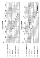
また、図6は、DLLクロック検知回路の動作シミュレーション波形を示す図である。図6(A)は、DLLクロック出力時のシミュレーション波形の例を示し、図6(B)は、DLLクロック消失時のシミュレーション波形の例を示している。 FIG. 6 is a diagram showing operation simulation waveforms of the DLL clock detection circuit. 6A shows an example of a simulation waveform when the DLL clock is output, and FIG. 6B shows an example of the simulation waveform when the DLL clock is lost.
なお、図6に示す波形例は、図4に示すDLLクロック検知回路31において、DLLクロックを検知するためのDラッチ回路として、Dラッチ回路105および106の2つ使用する場合の例であり、DLLクロック検知Enableの信号の活性化される(Highになる)期間は、DLLクロックの2サイクルに相当する期間となる。
The waveform example shown in FIG. 6 is an example in which two
最初に、DLLクロック出力時の動作を、図6(A)を参照して説明する。
図6(A)において、(イ)のDLLクロック検知Enableの信号を、時刻t1においてHighにして、DLLクロック検知回路31を活性化する。
First, the operation at the time of DLL clock output will be described with reference to FIG.
In FIG. 6A, the DLL clock detection enable signal of (A) is set to High at time t1, and the DLL
DLLクロックEnableを、時刻t1においてHighにすると、(ロ)のDLLクロックのクロックC1(DLLクロックEnableがhighになった後、2番目のクロック)のポジティブエッジ(立ち上がりエッジ)により、(ハ)に示す検知結果の信号が生成される。この検知結果の信号を基に、時刻t3において、(ニ)に示す更新Enable/Disable(この場合はEnable)がクロック検知結果の信号として生成される。この更新Enableの信号が、デューティ検知回路21、遅延制御回路13、およびDLLサイクルカウンタ18に出力される。
When the DLL clock Enable is set to High at time t1, the positive clock (rising edge) of the clock C1 of the DLL clock (b) (the second clock after the DLL clock Enable becomes high) is set to (c). A detection result signal is generated. Based on this detection result signal, at time t3, update Enable / Disable (in this case, Enable) shown in (d) is generated as a clock detection result signal. The update enable signal is output to the
この結果、DLLサイクルカウンタ18により、(ホ)に示す更新クロック信号が、時刻t4において生成され、この更新クロックが遅延制御回路13およびデューティ制御回路22に出力される。
As a result, an updated clock signal shown in (e) is generated by the
そして、遅延制御回路13は、DLLサイクルカウンタ18から受信した更新クロック、およびDLLクロック検知回路31から受信した更新Enable信号に従って、遅延回路12を通してDLLクロックの遅延調整を行なう。
Then, the
また、デューティ制御回路22は、DLLサイクルカウンタ18から受信した更新クロック、およびデューティ検知回路21から受信したデューティ判定結果の信号に従って、デューティ調整回路23を通してDLLクロックのデューティ調整(デューティが50%になるように調整)を行なう。
Further, the
一方、図6(B)に示す、DLLクロック消失時の波形において、時刻t1以前には、(ロ)に示すDLLクロックは正常にクロッキングしており、(ハ)に示す検知結果もHigh(クロッキング有り)となっており、また、(ニ)に示す更新Enable/Disable信号がHigh(クロッキング有り)の状態になっている。 On the other hand, in the waveform when the DLL clock disappears as shown in FIG. 6B, the DLL clock shown in (b) is normally clocked before time t1, and the detection result shown in (c) is also High ( The update enable / disable signal shown in (d) is in a high state (with clocking).
そして、時刻t1において、(イ)に示すDLLクロックEnable信号をHighにして、DLLクロック検知回路31におけるDLLクロックの検知処理を開始する。
At time t1, the DLL clock enable signal shown in (a) is set to High, and the DLL
しかしながら、この例では、DLLクロック検知Enable信号を、時刻t1においてHighにした時に、(ロ)に示すDLLクロックが消失(Highにスタック)している。 However, in this example, when the DLL clock detection enable signal is set to high at time t1, the DLL clock shown in (b) has disappeared (stacked to high).
このため、(ハ)に示す検知結果の信号は、時刻t2においてLow(クロッキングなし)となり、時刻t3において、(ニ)に示す更新Enable/Disableの信号がLow(更新Disable)となる。この更新Disableの信号がクロック検知結果の信号として、デューティ検知回路21、遅延制御回路13、およびDLLサイクルカウンタ18に通知される。
For this reason, the signal of the detection result shown in (c) becomes Low (no clocking) at time t2, and the update enable / disable signal shown in (d) becomes Low (update disable) at time t3. This update disable signal is notified to the
この結果、DLLサイクルカウンタ18により、(ホ)に示す更新クロックが生成されず、更新クロックが遅延制御回路13およびデューティ検知回路21に通知されない。これにより、デューティ検知回路21およびデューティ制御回路22におけるデューティの更新制御は停止される。また、遅延制御回路13における遅延量の更新制御は停止される。なお、この場合、デューティ検知回路21は、それまでデューティ調整量を保持し、遅延制御回路13は、それまでの遅延調整を保持する。
As a result, the
また、図7は、遅延制御回路13の構成例を示す図である。この遅延制御回路13は、遅延回路12における遅延量を位相検知回路16の出力信号(位相判定結果)に従って決定する回路である。
FIG. 7 is a diagram illustrating a configuration example of the
図7に示すように、遅延制御回路13は、加算器(加算回路)201と、Dラッチ回路202、203、204と、アンド回路205とを有している。そして、Dラッチ回路202、203、204の出力Qは、それぞれ加算器201に入力され、また、加算器201には位相検知回路16から出力される判定結果(カウントアップ信号Up、またはカウントダウン信号Down)の信号が入力される。この加算器201の各出力は、Dラッチ回路202、203、204のデータ入力端子Dに接続されている。
As illustrated in FIG. 7, the
また、2入力のアンド回路205の一方の入力端子には、DLLサイクルカウンタ18から出力される更新クロックの信号が入力され、2入力のアンド回路205のもう一方の入力端子には、DLLクロック検知回路31から出力されるクロック検知結果(更新Enable/Disable)が入力される。このアンド回路205の出力は、Dラッチ回路202、203、204のそれぞれのクロック入力端子Cに接続されている。
An update clock signal output from the
上記構成により、Dラッチ回路202、203、204には、現在の遅延量のデータがラッチされており、この現在の遅延量のデータは加算器201に入力されている。そして、この加算器201に、位相判定結果の信号(カウントUp/Down)が入力され、現在の遅延量のデータに対して、カウントUpまたはカウントDownの動作が行なわれ、遅延量が更新される。
With the above configuration, the current delay amount data is latched in the
そして、遅延更新クロック信号の活性時に、DLLクロック検知結果がHigh(更新Enable)の場合に、加算器201の出力信号(更新データ)をDラッチ回路202、203、204にラッチする。そして、Dラッチ回路202、203、204に保持された遅延量の更新データを遅延回路12へ出力する。
When the delayed update clock signal is active and the DLL clock detection result is High (update enable), the output signal (update data) of the
一方、遅延更新クロック信号の活性時に、DLLクロック検知結果がLow(更新Disable)の場合は、アンド回路205の出力はLowのままとなり、加算器201の出力信号(更新データ)はDラッチ回路202、203、204にラッチされない。このため、Dラッチ回路202、203、204のデータは更新されず、現在のデータがそのまま残ることになる。
On the other hand, if the DLL clock detection result is Low (update Disable) when the delayed update clock signal is active, the output of the AND
なお、図7に示す例では、3つのDラッチ回路202、203、204のみを示しているが、このDラッチ回路は、必要に応じて4個以上使用される場合がある。
In the example shown in FIG. 7, only three
また、図8は、デューティ検知回路の構成を示す図である。デューティ検知回路21は、DLLクロックのデューティを検知し、50%に対して判定を行なう回路である。
FIG. 8 is a diagram showing the configuration of the duty detection circuit. The
図8(A)に示すデューティ検知回路21において、DLLクロック検知回路31からクロック検知結果(Enable/Disable)の信号がインバータ301に入力される。インバータ301の出力信号は、インバータ302およびセレクタ306のON/OFF制御端子Sに入力される。
In the
また、DLLクロックがデューティ判定部303およびDラッチ回路304のデータ入力端子Dに入力され、デューティ判定部303の出力信号は、セレクタ306の一方の入力端子aの入力信号となる。Dラッチ回路304の出力Qの信号はインバータ305で論理反転されて、セレクタ306の他方の入力端子bの入力信号となる。
The DLL clock is input to the data input terminal D of the
デューティ判定部303は、入力されるDLLクロックのデューティを判定し、図8(B)に示すように、Hihgの期間が50%よりも大きい場合は、デューティの減少指令としてDown信号(Lowレベル)を出力する。また、図8(C)に示すように、Hihgの期間が50%よりも小さい場合は、デューティの増加指令としてUp信号(Highレベル)を出力する。
The
上記構成において、クロック検知結果の信号がHigh(クロッキング動作有り)の場合は、セレクタ306では、入力端子aによりデューティ判定部303側の出力信号が選択され、デューティ判定部303におけるデューティ判定結果の信号が出力される。
In the above configuration, when the signal of the clock detection result is High (with clocking operation), the
一方、クロック検知結果がLow(クロッキング動作無し)の場合は、セレクタ306では、入力端子bによりインバータ305の出力信を選択する。
On the other hand, when the clock detection result is Low (no clocking operation), the
この場合、Dラッチ回路304には、クロック検知結果がLowに遷移したときに、DLLクロックのスタックレベルがラッチされており、このDラッチ回路304に保持されたスタックレベルは、出力Qと接続されたインバータ305により論理反転され、セレクタ306の入力端子bの入力信号となる。
In this case, the
従って、クロック検知結果がLow(クロッキング動作無し)の場合において、スタックレベルがHighの時は、デューティ判定結果はLow(デューティDown)、スタックレベルがLowの時は、デューティ判定結果はHigh(デューティUp)が出力される。このHighまたはLowレベルに応じて、デューティをUpまたはDownさせDLLクロックを復帰させる。これにより、クロッキング動作の復帰(デューティ制御)を行なえるようになる。 Therefore, when the clock detection result is Low (no clocking operation), when the stack level is High, the duty determination result is Low (Duty Down), and when the stack level is Low, the duty determination result is High (Duty Up) is output. Depending on the high or low level, the duty is increased or decreased to recover the DLL clock. As a result, the clocking operation can be restored (duty control).
以上、本発明の実施の形態について説明したが、本発明のDLL回路は、上述の図示例にのみ限定されるものではなく、本発明の要旨を逸脱しない範囲内において種々変更を加え得ることは勿論である。 Although the embodiments of the present invention have been described above, the DLL circuit of the present invention is not limited to the above illustrated examples, and various modifications can be made without departing from the scope of the present invention. Of course.
11…初段回路、12…遅延回路、13…遅延制御回路、14…DQバッファ、15…DQレプリカ回路、16…位相検知回路、17…カウンタクロック生成回路、18…DLLサイクルカウンタ、21…デューティ検知回路、22…デューティ制御回路、23…デューティ調整回路、31…DLLクロック検知回路、101…インバータ、102、103、107…ナンド回路、104…RSラッチ回路、105、106…Dラッチ回路、201…加算器、202、203、204…Dラッチ回路、205…アンド回路、301、302、305…インバータ、303…デューティ判定部、304…Dラッチ回路、306…セレクタ
DESCRIPTION OF
Claims (10)
入力される第1のクロック信号の遅延量を制御する遅延信号を出力する遅延制御回路と、
前記遅延信号が入力され、前記遅延信号に基づいた遅延量を前記第1のクロック信号に付加し、DLLクロックとして出力する遅延回路と、
前記DLLクロックのクロッキング動作の有無を検知するDLLクロック検知回路と、
を備え、
前記DLLクロック検知回路は、前記クロッキング動作が検知されない場合に前記遅延制御回路による遅延量の更新動作を停止させること、
を特徴とするDLL回路。 A DLL (Delay-Locked Loop) circuit that adjusts and outputs the phase of a clock signal,
A delay control circuit for outputting a delay signal for controlling a delay amount of the input first clock signal;
A delay circuit that receives the delay signal, adds a delay amount based on the delay signal to the first clock signal, and outputs the delay clock as a DLL clock;
A DLL clock detection circuit for detecting the presence or absence of a clocking operation of the DLL clock;
With
The DLL clock detection circuit, when the clocking operation is not detected, to stop the delay amount update operation by the delay control circuit;
A DLL circuit characterized by the above.
入力される第1のクロック信号のデューティを制御するデューティ信号を出力するデューティ制御回路と、
前記デューティ信号が入力され、前記デューティ信号に基づいて前記第1のクロック信号のデューティを調整してDLLクロックとして出力するデューティ調整回路と、
前記DLLクロックのクロッキング動作の有無を検知するDLLクロック検知回路と、
を備え、
前記DLLクロック検知回路は、前記クロッキング動作が検知されない場合に前記デューティ制御回路によるデューティの更新動作を停止させること、
を特徴とするDLL回路。 A DLL circuit that adjusts and outputs a duty of a clock signal,
A duty control circuit for outputting a duty signal for controlling the duty of the input first clock signal;
A duty adjustment circuit that receives the duty signal, adjusts the duty of the first clock signal based on the duty signal, and outputs a DLL clock;
A DLL clock detection circuit for detecting the presence or absence of a clocking operation of the DLL clock;
With
The DLL clock detection circuit stops the duty update operation by the duty control circuit when the clocking operation is not detected;
A DLL circuit characterized by the above.
前記デューティ信号が入力され、前記デューティ信号に基づいて前記第1のクロック信号のデューティを調整して第2のクロック信号として出力するデューティ調整回路と、
前記デューティ調整回路から出力される第2のクロック信号の遅延量を制御する遅延信号を出力する遅延制御回路と、
前記遅延信号が入力され、前記遅延信号に基づいた遅延量を前記第2のクロック信号に付加し、DLLクロックとして出力する遅延回路と、
前記DLLクロックのクロッキング動作の有無を検知するDLLクロック検知回路と、
を備え、
前記DLLクロック検知回路は、前記DLLクロックのクロッキング動作が検知されない場合に、前記デューティ制御回路におけるデューティの更新動作、および前記遅延制御回路における遅延量の更新動作を停止させること、
を特徴とする請求項1に記載のDLL回路。 A duty control circuit for outputting a duty signal for controlling the duty of the input first clock signal;
A duty adjustment circuit that receives the duty signal, adjusts a duty of the first clock signal based on the duty signal, and outputs a second clock signal;
A delay control circuit that outputs a delay signal that controls a delay amount of the second clock signal output from the duty adjustment circuit;
A delay circuit that receives the delay signal, adds a delay amount based on the delay signal to the second clock signal, and outputs the delay clock as a DLL clock;
A DLL clock detection circuit for detecting the presence or absence of a clocking operation of the DLL clock;
With
The DLL clock detection circuit, when a clocking operation of the DLL clock is not detected, stops a duty update operation in the duty control circuit and a delay amount update operation in the delay control circuit;
The DLL circuit according to claim 1.
該DLLクロック検知回路を所定の周期ごとに所定の期間活性化させるDLLクロック検知Enable信号と、前記DLLクロックとを入力信号とし、
前記DLLクロック検知Enable信号が入力されている期間内における、前記DLLクロックのクロッキング回数を検出するカウンタ回路と、
前記カウンタ回路により検出された前記DLLクロックのクロッキング回数が所定数以上の場合に、DLLクロックのクロッキング有りの情報を保持し該情報を示す信号を出力するとともに、前記DLLクロックのクロッキング回数が所定数以下の場合に、DLLクロックのクロッキング無しの情報を保持し該情報を示す信号を出力するラッチ回路と、
を備えることを特徴とする請求項1から請求項3のいずれかに記載のDLL回路。 The DLL clock detection circuit includes:
The DLL clock detection enable signal for activating the DLL clock detection circuit for a predetermined period every predetermined period, and the DLL clock as input signals,
A counter circuit that detects the number of clocking of the DLL clock within a period in which the DLL clock detection Enable signal is input;
When the number of clocking of the DLL clock detected by the counter circuit is equal to or greater than a predetermined number, information indicating that the clocking of the DLL clock is held is output and a signal indicating the information is output, and the number of clocking of the DLL clock A latch circuit that holds information indicating no clocking of the DLL clock and outputs a signal indicating the information when
The DLL circuit according to any one of claims 1 to 3, further comprising:
前記DLLクロックを入力としてDQ信号を出力するDQバッファ回路と、
前記DQバッファのレプリカ回路であり、かつ前記DLLクロックが入力されるDQレプリカ回路と、
前記第1のクロック信号と前記DQレプリカ回路から出力されるクロック信号との位相の差を検知し、該位相差を位相判定結果の信号として出力する位相検知回路と、
を備えると共に、
前記遅延制御回路は、
現在の遅延量の情報を保持して出力するラッチ回路と、
前記位相検知回路から出力される位相判定結果の信号を入力とし、前記位相差と前記ラッチ回路に保持された現在の遅延量とを加算する加算回路と、
を備え、
前記遅延制御回路は、前記DLLクロック検知回路によりDLLクロックのクロッキング有りの信号が出力された場合、前記加算回路の加算結果を前記ラッチ回路に新たな遅延量の情報として保持させるように構成されたこと、
を特徴とする請求項4に記載のDLL回路。 The DLL circuit
A DQ buffer circuit for receiving the DLL clock and outputting a DQ signal;
A DQ replica circuit that is a replica circuit of the DQ buffer and to which the DLL clock is input;
A phase detection circuit that detects a phase difference between the first clock signal and the clock signal output from the DQ replica circuit, and outputs the phase difference as a signal of a phase determination result;
With
The delay control circuit includes:
A latch circuit that holds and outputs information of the current delay amount;
An addition circuit for adding a signal of a phase determination result output from the phase detection circuit and adding the phase difference and the current delay amount held in the latch circuit;
With
The delay control circuit is configured to hold the addition result of the addition circuit as new delay amount information in the latch circuit when a signal with clocking of the DLL clock is output by the DLL clock detection circuit. Was it,
The DLL circuit according to claim 4.
前記デューティ検知回路は、
DLLクロックのデューティを判定するデューティ判定部と、
前記DLLクロックのHighまたはLowのスタックレベルを保持するラッチ回路と、
前記DLLクロック検知回路によりDLLクロックのクロッキング有りの信号が出力された場合に、前記デューティ判定部の出力信号を選択して出力すると共に、前記DLLクロック検知回路によりDLLクロックのクロッキング無しの信号が出力された場合に、前記ラッチ回路に保持されたスタックレベルの信号またはその反転信号を選択して出力するセレクタと、
を備えることを特徴とする請求項4または5に記載のDLL回路。 The DLL circuit includes a duty detection circuit that detects the duty of the DLL clock;
The duty detection circuit includes:
A duty determination unit for determining the duty of the DLL clock;
A latch circuit for holding a high or low stack level of the DLL clock;
When a signal with clocking of the DLL clock is output by the DLL clock detection circuit, the output signal of the duty determination unit is selected and output, and a signal without clocking of the DLL clock is output by the DLL clock detection circuit Is output when the stack level signal held in the latch circuit or its inverted signal is selected and output,
The DLL circuit according to claim 4, further comprising:
前記請求項1から請求項6のいずれかに記載のDLL回路を備えたこと
を特徴とする半導体装置。 In a semiconductor device provided with a DLL circuit,
A semiconductor device comprising the DLL circuit according to claim 1.
クロック信号のクロッキング動作がないときに遅延制御を停止する手段を
備えたことを特徴とするDLL回路。 A DLL circuit,
A DLL circuit comprising means for stopping delay control when there is no clock signal clocking operation.
クロック信号のクロッキング動作がないときにデューティ制御を停止する手段を
備えたことを特徴とするDLL回路。 A DLL circuit,
A DLL circuit comprising means for stopping duty control when there is no clock signal clocking operation.
備えたことを特徴とする請求項8に記載のDLL回路。 9. The DLL circuit according to claim 8, further comprising means for stopping duty control when there is no clock signal clocking operation.
Priority Applications (3)
| Application Number | Priority Date | Filing Date | Title |
|---|---|---|---|
| JP2008129638A JP2009278528A (en) | 2008-05-16 | 2008-05-16 | Dll circuit, and semiconductor device |
| US12/465,355 US8013645B2 (en) | 2008-05-16 | 2009-05-13 | DLL circuit adapted to semiconductor device |
| US14/020,445 USRE45604E1 (en) | 2008-05-16 | 2013-09-06 | DLL circuit adapted to semiconductor device |
Applications Claiming Priority (1)
| Application Number | Priority Date | Filing Date | Title |
|---|---|---|---|
| JP2008129638A JP2009278528A (en) | 2008-05-16 | 2008-05-16 | Dll circuit, and semiconductor device |
Publications (2)
| Publication Number | Publication Date |
|---|---|
| JP2009278528A true JP2009278528A (en) | 2009-11-26 |
| JP2009278528A5 JP2009278528A5 (en) | 2010-12-16 |
Family
ID=41315597
Family Applications (1)
| Application Number | Title | Priority Date | Filing Date |
|---|---|---|---|
| JP2008129638A Ceased JP2009278528A (en) | 2008-05-16 | 2008-05-16 | Dll circuit, and semiconductor device |
Country Status (2)
| Country | Link |
|---|---|
| US (2) | US8013645B2 (en) |
| JP (1) | JP2009278528A (en) |
Cited By (4)
| Publication number | Priority date | Publication date | Assignee | Title |
|---|---|---|---|---|
| JP2011142566A (en) * | 2010-01-08 | 2011-07-21 | Elpida Memory Inc | Semiconductor device |
| US8630144B2 (en) | 2010-12-13 | 2014-01-14 | Elpida Memory, Inc. | Semiconductor device outputting read data in synchronization with clock signal |
| US8947971B2 (en) | 2010-12-16 | 2015-02-03 | Ps4 Luxco S.A.R.L. | Semiconductor device generating a clock signal when required |
| US9209817B2 (en) | 2011-05-27 | 2015-12-08 | Renesas Electronics Corporation | Clock generation circuit, display device drive circuit, and control method of clock generation circuit |
Families Citing this family (8)
| Publication number | Priority date | Publication date | Assignee | Title |
|---|---|---|---|---|
| KR100930416B1 (en) * | 2008-08-11 | 2009-12-08 | 주식회사 하이닉스반도체 | Semiconductor integrated circuit and method of controlling the same |
| KR101008990B1 (en) | 2008-12-05 | 2011-01-17 | 주식회사 하이닉스반도체 | Buffer enable signal generating circuit and input circuit using the same |
| KR101659840B1 (en) * | 2010-03-11 | 2016-09-30 | 삼성전자주식회사 | Digital DLL having duty correction circuit of skewed gate type and duty correction method thereof |
| JP2011223436A (en) * | 2010-04-13 | 2011-11-04 | Elpida Memory Inc | Semiconductor circuit |
| JP5241776B2 (en) * | 2010-06-25 | 2013-07-17 | 株式会社日立製作所 | Duty compensation circuit |
| JP5600049B2 (en) * | 2010-11-11 | 2014-10-01 | ピーエスフォー ルクスコ エスエイアールエル | Semiconductor device |
| JP5592238B2 (en) * | 2010-11-18 | 2014-09-17 | ピーエスフォー ルクスコ エスエイアールエル | Semiconductor device and control method thereof |
| US9443602B2 (en) * | 2013-08-23 | 2016-09-13 | Kabushiki Kaisha Toshiba | Storage device and data latch timing adjustment method |
Citations (5)
| Publication number | Priority date | Publication date | Assignee | Title |
|---|---|---|---|---|
| JPH0370314A (en) * | 1989-08-10 | 1991-03-26 | Fujitsu Ltd | Clock interrupt detection circuit |
| JPH10322182A (en) * | 1997-05-19 | 1998-12-04 | Oki Electric Ind Co Ltd | Clock-disconnection detecting circuit |
| JP2007116574A (en) * | 2005-10-24 | 2007-05-10 | Elpida Memory Inc | Dll circuit, and semiconductor device providing the same |
| JP2007121114A (en) * | 2005-10-28 | 2007-05-17 | Elpida Memory Inc | Duty detecting circuit and dll circuit and semiconductor device equipped therewith |
| JP2007243735A (en) * | 2006-03-09 | 2007-09-20 | Elpida Memory Inc | Dll circuit and semiconductor device comprising the same |
Family Cites Families (34)
| Publication number | Priority date | Publication date | Assignee | Title |
|---|---|---|---|---|
| KR100366618B1 (en) * | 2000-03-31 | 2003-01-09 | 삼성전자 주식회사 | Delay locked loop circuit for correcting duty cycle of clock signal and delay locking method |
| JP3888603B2 (en) | 2000-07-24 | 2007-03-07 | 株式会社ルネサステクノロジ | Clock generation circuit, control method, and semiconductor memory device |
| US6950487B2 (en) * | 2001-05-18 | 2005-09-27 | Micron Technology, Inc. | Phase splitter using digital delay locked loops |
| DE10149584B4 (en) * | 2001-10-08 | 2007-11-22 | Infineon Technologies Ag | Delay locked loop |
| US7336752B2 (en) * | 2002-12-31 | 2008-02-26 | Mosaid Technologies Inc. | Wide frequency range delay locked loop |
| KR100540930B1 (en) * | 2003-10-31 | 2006-01-11 | 삼성전자주식회사 | Delay-locked loop circuit |
| KR100594258B1 (en) * | 2004-02-26 | 2006-06-30 | 삼성전자주식회사 | Duty cycle correction circuit and method reducing jitters using phase-mixed output signal |
| KR100537196B1 (en) * | 2004-03-05 | 2005-12-16 | 주식회사 하이닉스반도체 | Delay locked loop in semiconductor memory device and its clock locking method |
| KR100645461B1 (en) * | 2004-06-30 | 2006-11-15 | 주식회사 하이닉스반도체 | A digital delay locked loop able to correct duty cycle and its cotrol method |
| US7180377B1 (en) * | 2005-01-18 | 2007-02-20 | Silicon Clocks Inc. | Method and apparatus for a hybrid phase lock loop frequency synthesizer |
| US7428284B2 (en) * | 2005-03-14 | 2008-09-23 | Micron Technology, Inc. | Phase detector and method providing rapid locking of delay-lock loops |
| US7259604B2 (en) * | 2005-08-03 | 2007-08-21 | Micron Technology, Inc. | Initialization scheme for a reduced-frequency, fifty percent duty cycle corrector |
| US7479816B2 (en) * | 2005-10-14 | 2009-01-20 | Texas Instruments Incorporated | Generating multiple delayed signals of different phases from a reference signal using delay locked loop (DLL) |
| KR100776906B1 (en) * | 2006-02-16 | 2007-11-19 | 주식회사 하이닉스반도체 | Delay locked loop with a function for implementing locking operation periodically during power down mode and locking operation method of the same |
| JP5134779B2 (en) * | 2006-03-13 | 2013-01-30 | ルネサスエレクトロニクス株式会社 | Delay synchronization circuit |
| KR100853462B1 (en) * | 2006-08-31 | 2008-08-21 | 주식회사 하이닉스반도체 | Semiconductor memory device |
| KR100810073B1 (en) * | 2006-09-29 | 2008-03-05 | 주식회사 하이닉스반도체 | Semiconductor memory device and the method for operating the same |
| KR100807113B1 (en) * | 2006-09-29 | 2008-02-26 | 주식회사 하이닉스반도체 | Semiconductor memory device and driving method thereof |
| KR100840697B1 (en) * | 2006-10-30 | 2008-06-24 | 삼성전자주식회사 | Delay-locked loop circuit for generating multi-phase clock signals and method of controlling the same |
| US7701272B2 (en) * | 2007-05-31 | 2010-04-20 | Micron Technology, Inc. | Method and apparatus for output data synchronization with system clock |
| KR100873624B1 (en) * | 2007-11-09 | 2008-12-12 | 주식회사 하이닉스반도체 | Power down mode control apparatus and dll circuit with the same |
| US8045669B2 (en) * | 2007-11-29 | 2011-10-25 | Qualcomm Incorporated | Digital phase-locked loop operating based on fractional input and output phases |
| KR100973222B1 (en) * | 2007-12-26 | 2010-07-30 | 주식회사 동부하이텍 | Delay-locked loop for controlling timing |
| US7728638B2 (en) * | 2008-04-25 | 2010-06-01 | Qimonda North America Corp. | Electronic system that adjusts DLL lock state acquisition time |
| KR100958811B1 (en) * | 2008-09-02 | 2010-05-24 | 주식회사 하이닉스반도체 | Delay locked loop circuit |
| KR100985413B1 (en) * | 2008-10-14 | 2010-10-06 | 주식회사 하이닉스반도체 | Delay circuit and delay locked loop circuit including the same |
| TWI401693B (en) * | 2009-01-05 | 2013-07-11 | Nanya Technology Corp | Voltage providing circuit, and signal delaying system utilizing the voltage providing circuit |
| US8699647B2 (en) * | 2009-06-23 | 2014-04-15 | Intel Mobile Communications GmbH | Fast phase alignment for clock and data recovery |
| KR101264729B1 (en) * | 2009-12-31 | 2013-05-15 | 엘지디스플레이 주식회사 | Apparatus for detecting jitter of phase locked loop |
| KR101212724B1 (en) * | 2010-05-31 | 2012-12-14 | 에스케이하이닉스 주식회사 | Clock generation circuit and delay locked loop using the same |
| US8179162B2 (en) * | 2010-07-13 | 2012-05-15 | Taiwan Semiconductor Manufacturing Company, Ltd. | Phase-lock assistant circuitry |
| KR20120063864A (en) * | 2010-12-08 | 2012-06-18 | 한국전자통신연구원 | Differential controlled phase locked loop circuit |
| KR20120121685A (en) * | 2011-04-27 | 2012-11-06 | 에스케이하이닉스 주식회사 | Semiconductor device and delay locked loop circuit of semiconductor device |
| WO2012153375A1 (en) * | 2011-05-06 | 2012-11-15 | 富士通株式会社 | Clock generation circuit |
-
2008
- 2008-05-16 JP JP2008129638A patent/JP2009278528A/en not_active Ceased
-
2009
- 2009-05-13 US US12/465,355 patent/US8013645B2/en not_active Expired - Fee Related
-
2013
- 2013-09-06 US US14/020,445 patent/USRE45604E1/en active Active
Patent Citations (5)
| Publication number | Priority date | Publication date | Assignee | Title |
|---|---|---|---|---|
| JPH0370314A (en) * | 1989-08-10 | 1991-03-26 | Fujitsu Ltd | Clock interrupt detection circuit |
| JPH10322182A (en) * | 1997-05-19 | 1998-12-04 | Oki Electric Ind Co Ltd | Clock-disconnection detecting circuit |
| JP2007116574A (en) * | 2005-10-24 | 2007-05-10 | Elpida Memory Inc | Dll circuit, and semiconductor device providing the same |
| JP2007121114A (en) * | 2005-10-28 | 2007-05-17 | Elpida Memory Inc | Duty detecting circuit and dll circuit and semiconductor device equipped therewith |
| JP2007243735A (en) * | 2006-03-09 | 2007-09-20 | Elpida Memory Inc | Dll circuit and semiconductor device comprising the same |
Cited By (6)
| Publication number | Priority date | Publication date | Assignee | Title |
|---|---|---|---|---|
| JP2011142566A (en) * | 2010-01-08 | 2011-07-21 | Elpida Memory Inc | Semiconductor device |
| US8630144B2 (en) | 2010-12-13 | 2014-01-14 | Elpida Memory, Inc. | Semiconductor device outputting read data in synchronization with clock signal |
| US8773943B2 (en) | 2010-12-13 | 2014-07-08 | Yuki Nakamura | Semiconductor device outputting read data in synchronization with clock signal |
| US9135979B2 (en) | 2010-12-13 | 2015-09-15 | Ps4 Luxco S.A.R.L. | Semiconductor device outputting read data in synchronization with clock signal |
| US8947971B2 (en) | 2010-12-16 | 2015-02-03 | Ps4 Luxco S.A.R.L. | Semiconductor device generating a clock signal when required |
| US9209817B2 (en) | 2011-05-27 | 2015-12-08 | Renesas Electronics Corporation | Clock generation circuit, display device drive circuit, and control method of clock generation circuit |
Also Published As
| Publication number | Publication date |
|---|---|
| US20090284290A1 (en) | 2009-11-19 |
| US8013645B2 (en) | 2011-09-06 |
| USRE45604E1 (en) | 2015-07-07 |
Similar Documents
| Publication | Publication Date | Title |
|---|---|---|
| JP2009278528A (en) | Dll circuit, and semiconductor device | |
| US6683478B2 (en) | Apparatus for ensuring correct start-up and phase locking of delay locked loop | |
| US7405603B2 (en) | Delayed Locked Loop Circuit | |
| US7994834B2 (en) | Duty cycle corrector and clock generator having the same | |
| KR100759786B1 (en) | Delay locked loop of a semiconductor device and method of controlling the same | |
| KR20140012312A (en) | Delay locked loop circuit and method of driving the same | |
| US7414446B2 (en) | DLL circuit of semiconductor memory apparatus and method of delaying and locking clock in semiconductor memory apparatus | |
| US7777542B2 (en) | Delay locked loop | |
| JP4276092B2 (en) | Integrated circuit device | |
| JP2008199573A (en) | Delay locked loop circuit with duty cycle correction function and method of controlling the same | |
| US20070069783A1 (en) | Delay locked loop in synchronous semiconductor memory device and driving method thereof | |
| US20150280721A1 (en) | Clock delay detecting circuit and semiconductor apparatus using the same | |
| KR20080098197A (en) | Delay-locked loop, integrated circuit having the same and method of driving the same | |
| JP2010287304A (en) | Semiconductor memory device and method of generating output enable signal | |
| JP2010124020A (en) | Dll circuit and semiconductor device including the same | |
| US8085072B2 (en) | Semiconductor integrated circuit having delay locked loop circuit | |
| KR101094932B1 (en) | Delay locked loop circuit | |
| US7872508B2 (en) | Delay locked loop circuit | |
| US8446197B2 (en) | Delay locked loop and method for driving the same | |
| US8638137B2 (en) | Delay locked loop | |
| JP2010154019A (en) | Dll circuit and semiconductor device with the same, and data processing system | |
| US20120249199A1 (en) | Internal clock generator and operating method thereof | |
| US20070216456A1 (en) | Delay locked loop and method of locking a clock signal | |
| US20090174447A1 (en) | Semiconductor integrated circuit and method of controlling the same | |
| KR20080002590A (en) | Delay locked loop circuit |
Legal Events
| Date | Code | Title | Description |
|---|---|---|---|
| A521 | Written amendment |
Free format text: JAPANESE INTERMEDIATE CODE: A523 Effective date: 20101029 |
|
| A621 | Written request for application examination |
Free format text: JAPANESE INTERMEDIATE CODE: A621 Effective date: 20110309 |
|
| A711 | Notification of change in applicant |
Free format text: JAPANESE INTERMEDIATE CODE: A711 Effective date: 20131029 |
|
| A711 | Notification of change in applicant |
Free format text: JAPANESE INTERMEDIATE CODE: A711 Effective date: 20131030 |
|
| A131 | Notification of reasons for refusal |
Free format text: JAPANESE INTERMEDIATE CODE: A131 Effective date: 20131203 |
|
| RD02 | Notification of acceptance of power of attorney |
Free format text: JAPANESE INTERMEDIATE CODE: A7422 Effective date: 20131211 |
|
| RD04 | Notification of resignation of power of attorney |
Free format text: JAPANESE INTERMEDIATE CODE: A7424 Effective date: 20131225 |
|
| A521 | Written amendment |
Free format text: JAPANESE INTERMEDIATE CODE: A523 Effective date: 20140120 |
|
| A601 | Written request for extension of time |
Free format text: JAPANESE INTERMEDIATE CODE: A601 Effective date: 20140225 |
|
| A602 | Written permission of extension of time |
Free format text: JAPANESE INTERMEDIATE CODE: A602 Effective date: 20140306 |
|
| A521 | Written amendment |
Free format text: JAPANESE INTERMEDIATE CODE: A523 Effective date: 20140603 |
|
| A01 | Written decision to grant a patent or to grant a registration (utility model) |
Free format text: JAPANESE INTERMEDIATE CODE: A01 Effective date: 20141216 |
|
| A045 | Written measure of dismissal of application |
Free format text: JAPANESE INTERMEDIATE CODE: A045 Effective date: 20150421 |