JP2009268564A - Vacuum cleaner - Google Patents
Vacuum cleaner Download PDFInfo
- Publication number
- JP2009268564A JP2009268564A JP2008119561A JP2008119561A JP2009268564A JP 2009268564 A JP2009268564 A JP 2009268564A JP 2008119561 A JP2008119561 A JP 2008119561A JP 2008119561 A JP2008119561 A JP 2008119561A JP 2009268564 A JP2009268564 A JP 2009268564A
- Authority
- JP
- Japan
- Prior art keywords
- dust
- dust collection
- opening
- filter
- vacuum cleaner
- Prior art date
- Legal status (The legal status is an assumption and is not a legal conclusion. Google has not performed a legal analysis and makes no representation as to the accuracy of the status listed.)
- Pending
Links
Images
Landscapes
- Filters For Electric Vacuum Cleaners (AREA)
Abstract
【課題】衛生的な電気掃除機を提供する。
【解決手段】本体部2内に配される電動送風機6と、電動送風機6の上流側の本体部2内に着脱自在に配されるとともに、上面を開口する上面開口部10bと周面に開口して接線方向に空気を流入させる流入口10aとを有する集塵容器10と、集塵容器10内に立設されるとともに、周面に形成される開口部11aと集塵容器10の底面を貫通して下端を開口する流出口11bとを有して集塵容器10内の空気を開口部11a及び流出口11bを介して流出させる内筒11と、開口部11aに設けられるフィルタ12と、上面開口部10bを塞いで集塵容器10に対して着脱自在の蓋体13と、蓋体13と一体に設けられて蓋体13の着脱時にフィルタ12に摺動する清掃部材14とを備えた。
【選択図】図2A hygienic vacuum cleaner is provided.
An electric blower 6 disposed in a main body 2 and a main body 2 upstream of the electric blower 6 are detachably disposed, and an upper surface opening 10b that opens an upper surface and an opening in a peripheral surface. In addition, the dust collection container 10 having an inlet 10a that allows air to flow in a tangential direction, and the opening 11a formed on the peripheral surface of the dust collection container 10 and the bottom surface of the dust collection container 10 are provided. An inner cylinder 11 that has an outlet 11b that passes through and opens at the lower end and allows the air in the dust collecting container 10 to flow out through the opening 11a and the outlet 11b, and a filter 12 that is provided in the opening 11a, A lid body 13 that closes the upper surface opening 10b and is detachable from the dust collecting container 10, and a cleaning member 14 that is provided integrally with the lid body 13 and slides on the filter 12 when the lid body 13 is attached or detached. .
[Selection] Figure 2
Description
本発明は、旋回気流によって塵埃を分離する集塵容器を備えた電気掃除機に関する。 The present invention relates to a vacuum cleaner provided with a dust collecting container that separates dust by a swirling airflow.
従来の電気掃除機は特許文献1に開示されている。この電気掃除機は吸込口体に接続される延長パイプに集塵容器が着脱自在に設けられる。集塵容器は上面を開口した有底筒状に形成され、周面には延長パイプから接線方向に気流が流入する流入口が設けられる。延長パイプには集塵容器の中心軸上に配される筒状の内筒が設けられる。内筒は周面にフィルタを有した開口部が設けられ、上端を開口した流出口を介して延長パイプに連通する。
A conventional vacuum cleaner is disclosed in
電動送風機の駆動により塵埃を含んだ空気が吸込口体から吸い込まれ、延長パイプを流通して流入口から集塵容器に流入する。集塵容器に流入した空気は集塵容器内で旋回し、遠心力により塵埃が分離される。塵埃を分離された空気は開口部から内筒に流入し、流出口を介して流出する。流出口から流出した空気は延長パイプ及び電動送風機を通って外部に排気される。 Air containing dust is sucked from the suction port body by driving the electric blower, flows through the extension pipe, and flows into the dust collecting container from the inlet. The air flowing into the dust collecting container swirls in the dust collecting container, and the dust is separated by centrifugal force. The air from which the dust has been separated flows into the inner cylinder from the opening and flows out through the outlet. The air flowing out from the outlet is exhausted to the outside through the extension pipe and the electric blower.
また、集塵容器の上面には内筒が嵌合する清掃部材が設けられる。内筒と一体の延長パイプから集塵容器を脱着すると清掃部材が開口部のフィルタに摺動し、フィルタに付着した塵埃が除去される。そして、集塵容器を運搬し、清掃部材を取り外して集塵容器内の塵埃が廃棄される。 Moreover, the cleaning member which an inner cylinder fits in is provided in the upper surface of a dust collecting container. When the dust collecting container is detached from the extension pipe integral with the inner cylinder, the cleaning member slides on the filter of the opening, and dust attached to the filter is removed. Then, the dust collecting container is transported, the cleaning member is removed, and the dust in the dust collecting container is discarded.
しかしながら、上記従来の電気掃除機によると、塵埃を廃棄する際に運搬される集塵容器は上面に配した清掃部材に内筒が挿通される孔が開口する。また、清掃部材の上面にはフィルタと摺動した際に脱落した塵埃が付着する。このため、集塵容器の運搬時に舞い上がって清掃部材の孔から流出した塵埃や清掃部材上に堆積した塵埃が室内等に落下して不衛生になる問題があった。加えて、集塵容器から清掃部材を取り外す際に使用者の手指が汚れて不衛生になる問題もあった。 However, according to the conventional vacuum cleaner, the dust collecting container transported when the dust is discarded has a hole through which the inner cylinder is inserted into the cleaning member disposed on the upper surface. Also, dust that has fallen off when sliding with the filter adheres to the upper surface of the cleaning member. For this reason, there has been a problem that dust that has risen during transportation of the dust collecting container and has flowed out of the hole of the cleaning member or accumulated on the cleaning member falls into the room and becomes unsanitary. In addition, when removing the cleaning member from the dust collecting container, there is also a problem that the user's fingers become dirty and unsanitary.
本発明は、衛生的な電気掃除機を提供することを目的とする。 An object of this invention is to provide a sanitary vacuum cleaner.
上記目的を達成するために本発明は、
本体部内に配される電動送風機と、
前記電動送風機の上流側の前記本体部内に着脱自在に配されるとともに、上面を開口する上面開口部と、周面に開口して接線方向に空気を流入させる流入口とを有して旋回気流により塵埃を分離する集塵容器と、
前記集塵容器内に立設されるとともに、周面に形成される開口部と、前記集塵容器の底面を貫通して下端を開口する流出口とを有し、前記集塵容器内の空気を前記開口部及び前記流出口を介して流出させる内筒と、
前記開口部に設けられるフィルタと、
前記上面開口部を塞いで前記集塵容器に対して着脱自在の蓋体と、
前記蓋体と一体に設けられて前記蓋体の着脱時に前記フィルタに摺動する清掃部材と、
を備えたことを特徴としている。
In order to achieve the above object, the present invention provides:
An electric blower arranged in the main body,
A swirling airflow that is detachably arranged in the main body portion upstream of the electric blower and has an upper surface opening portion that opens the upper surface and an inlet port that opens to the peripheral surface and allows air to flow in a tangential direction. A dust collecting container for separating the dust by
The air in the dust collection container has an opening formed in the peripheral surface and having an opening formed in the peripheral surface and an outlet opening through the bottom surface of the dust collection container and opening the lower end. An inner cylinder that flows out through the opening and the outlet,
A filter provided in the opening;
A lid that covers the top opening and is detachable from the dust collecting container;
A cleaning member provided integrally with the lid and sliding on the filter when the lid is attached and detached;
It is characterized by having.
この構成によると、電動送風機の駆動によって流入口から集塵容器内に塵埃を含む空気が流入し、集塵容器内で旋回して塵埃が分離される。塵埃が分離した空気はフィルタを有した開口部から内筒に流入し、下方の流出口から流出する。流出口から流出した空気は電動送風機を介して本体部の外部に排気される。塵埃の廃棄時に集塵容器は本体部から脱着して運搬され、蓋体が取り外されされる。この時、蓋体と一体の清掃部材が内筒の開口部に設けたフィルタと摺動し、フィルタに付着した塵埃が集塵容器内に落下する。そして、集塵容器内の塵埃が廃棄される。 According to this configuration, air containing dust flows into the dust collecting container from the inlet by driving the electric blower, and the dust is separated by rotating in the dust collecting container. The air from which the dust is separated flows into the inner cylinder from the opening having the filter and flows out from the lower outlet. The air that flows out from the outlet is exhausted to the outside of the main body through an electric blower. When the dust is discarded, the dust collecting container is detached from the main body and transported, and the lid is removed. At this time, the cleaning member integrated with the lid slides with the filter provided in the opening of the inner cylinder, and the dust attached to the filter falls into the dust collecting container. And the dust in a dust container is discarded.
また本発明は、上記構成の電気掃除機において、前記集塵容器に一体の集塵フィルタを前記流出口の下方に設けたことを特徴としている。この構成によると、内筒を流通する空気に含まれる微細な塵埃が集塵フィルタにより捕集される。 According to the present invention, in the vacuum cleaner configured as described above, a dust collection filter integrated with the dust collection container is provided below the outlet. According to this configuration, fine dust contained in the air flowing through the inner cylinder is collected by the dust collection filter.
また本発明は、上記構成の電気掃除機において、前記内筒の上面が開口して前記蓋体によって塞がれることを特徴としている。この構成によると、集塵フィルタ上の塵埃が内筒を通って廃棄される。 Further, the present invention is characterized in that, in the vacuum cleaner having the above-described configuration, an upper surface of the inner cylinder is opened and closed by the lid. According to this configuration, dust on the dust collection filter is discarded through the inner cylinder.
また本発明は、上記構成の電気掃除機において、前記集塵フィルタは隙間を有して前記集塵容器に対向することを特徴としている。この構成によると、集塵フィルタと集塵容器の隙間によって気流路が拡大され、内筒よりも大きな断面積を有する集塵フィルタにより微細な塵埃が捕集される。 Moreover, the present invention is characterized in that, in the vacuum cleaner having the above-described configuration, the dust collecting filter has a gap and faces the dust collecting container. According to this configuration, the air flow path is enlarged by the gap between the dust collection filter and the dust collection container, and fine dust is collected by the dust collection filter having a larger cross-sectional area than the inner cylinder.
また本発明は、上記構成の電気掃除機において、前記集塵容器の底面に突設される突起部を有し、前記集塵フィルタをスポンジ状に形成するとともに軸方向に可動にしたことを特徴としている。この構成によると、集塵容器を本体部から脱着した際に集塵フィルタを軸方向に移動させると、スポンジ状の集塵フィルタが突起部によって伸縮する。これにより、集塵フィルタの水洗いが行われる。また、内筒の上面が開口する場合は、集塵フィルタ内に含まれた塵埃が伸縮により表面に露出して内筒を介して廃棄される。 According to the present invention, in the electric vacuum cleaner having the above-described structure, the dust collecting container has a protrusion protruding from the bottom surface of the dust collecting container, and the dust collecting filter is formed in a sponge shape and movable in the axial direction. It is said. According to this configuration, when the dust collection filter is moved in the axial direction when the dust collection container is detached from the main body, the sponge-like dust collection filter expands and contracts by the protrusion. Thereby, the dust collecting filter is washed with water. Further, when the upper surface of the inner cylinder opens, the dust contained in the dust collection filter is exposed to the surface by expansion and contraction and is discarded through the inner cylinder.
また本発明は、上記構成の電気掃除機において、前記電動送風機を前記集塵容器の下方に配置し、前記電動送風機の回転軸と前記内筒の中心軸とを直線状に配置したことを特徴としている。 Further, the present invention is characterized in that, in the vacuum cleaner having the above-described configuration, the electric blower is disposed below the dust collecting container, and the rotation shaft of the electric blower and the central axis of the inner cylinder are arranged linearly. It is said.
また本発明は、上記構成の電気掃除機において、前記内筒の中心軸及び前記電動送風機の回転軸を傾斜したことを特徴としている。 Moreover, the present invention is characterized in that, in the vacuum cleaner configured as described above, the central axis of the inner cylinder and the rotation axis of the electric blower are inclined.
本発明によると、内筒が集塵容器の底面を貫通して下端を開口する流出口を有し、集塵容器の上面開口部を覆う蓋体とフィルタと摺動する清掃部材とが一体に設けられる。これにより、集塵容器を脱着して運搬する際に塵埃の落下を防止するとともに、使用者が清掃部材に触れることなく蓋体とともに清掃部材を取り外すことができる。従って、衛生的な電気掃除機を得ることができる。 According to the present invention, the inner cylinder has an outlet that passes through the bottom surface of the dust collecting container and opens the lower end, and the cover that covers the upper surface opening of the dust collecting container and the cleaning member that slides on the filter are integrated. Provided. This prevents the dust from falling when the dust collection container is detached and transported, and the cleaning member can be removed together with the lid without the user touching the cleaning member. Therefore, a sanitary vacuum cleaner can be obtained.
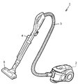
以下に本発明の実施形態を図面を参照して説明する。図1は一実施形態の電気掃除機を示す斜視図である。電気掃除機1は電動送風機6(図2参照)を内装した本体部2を備えている。床面に対向する吸込口体5には樹脂成形品の延長パイプ4が接続され、可撓性の接続ホース3によって本体部2と延長パイプ4とが接続される。
Embodiments of the present invention will be described below with reference to the drawings. FIG. 1 is a perspective view showing a vacuum cleaner according to an embodiment. The
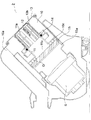
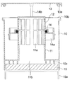
図2は本体部2の縦断面図を示している。本体部2の下部には電動送風機6が配され、電動送風機6の上方には集塵容器10が配される。集塵容器10は本体部2の上方に引き出して着脱自在になっており、接続ホース3(図1参照)に連通して周面の接線方向に気流を流入させる流入口10aが設けられる。
FIG. 2 shows a longitudinal sectional view of the
集塵容器10は断面円形の有底筒状に形成され、集塵容器10及び電動送風機6の中心軸が傾斜して略一直線上に配される。集塵容器10の上面には上面開口部10bが開口し、上面開口部10bは着脱自在の蓋体13により塞がれる。蓋体13には清掃部材14が一体に取付けられる。
The
集塵容器10の中央には集塵容器10と一体に形成される内筒11が立設される。内筒11は上端が閉塞される。内筒11の周面には開口部11aが形成され、下端は集塵容器10の底面を貫通して流出口11bが形成される。開口部11aにはメッシュ状のフィルタ12が設けられる。
An
流出口11bの下方にはスポンジ状の集塵フィルタ15が配される。集塵フィルタ15は集塵容器11に一体のフィルタケース15aにより保持され、集塵容器10の底面に対向する。フィルタケース15aは集塵容器110の軸方向上側に向けて可動に取り付けられ、集塵容器10の底面には複数の環状のリブから成る突起部10cが下方に突出する。
A sponge-like
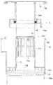
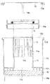
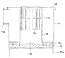
図3は集塵容器10から蓋体13を取り外した状態の正面断面図を示している。また、図4は図3のA方向から視た側面断面図を示している。蓋体13の周部にはパッキン13aが設けられ、集塵容器10は上面開口部10bの周縁に段部10dが形成される。これにより、パッキン13aが段部10dのパッキン13aと対向する面に接して上面開口部10bが封止される。
FIG. 3 shows a front sectional view of the
清掃部材14は内筒11のフィルタ12に摺動する環状のブラシ状に形成され、ハウジング14aにより保持される。ハウジング14aには上方に延びて蓋体13に連結される複数のシャフト14bが設けられる。これにより、蓋体13と清掃部材14とが一体化される。内筒11の周面にはシャフト14bが嵌合する溝11cが形成される。シャフト14bが溝11cに案内されることにより、蓋体13が集塵容器10に対して着脱される。この時、図5に示すように、清掃部材14がフィルタ12に摺動する。
The cleaning
上記構成の電気掃除機1において、電動送風機6を駆動すると塵埃を含んだ空気が吸込口体5から吸い込まれ、延長パイプ4及び接続ホース3を介して集塵容器10に導かれる。流入口10aから集塵容器10に流入した気流は旋回して遠心力によって塵埃が分離される。
In the
塵埃を分離した空気は開口部11aのフィルタ12を介して内筒11に流入する。この時、気流に含まれた微細な塵埃はフィルタ12により捕集される。内筒11を流通する空気は流出口11b介して集塵フィルタ15を通過する。これにより、集塵容器10内で分離されなかった微細な塵埃が集塵フィルタ15によって捕集される。集塵フィルタ15を通過した空気は電動送風機6に導かれ、外部に排気される。
The air from which the dust has been separated flows into the
集塵フィルタ15は突起部10cによって隙間D(図2参照)を介して集塵容器10の底面に対向する。このため、隙間Dにより流出口11bから気流が広がり、流出口11bよりも広い断面積を有する集塵フィルタ15により塵埃を捕集することができる。従って、集塵フィルタ15の目詰まりによるメンテナンスを削減することができる。尚、環状の各突起部10cには内周側から外周側に気流を流通させる切欠きや孔が設けられる。
The
集塵容器10内に塵埃が溜まると集塵容器10は本体部2から脱着して廃棄場所に運搬され、蓋体3を取り外される。この時、清掃部材14がフィルタ12と摺動してフィルタ12に付着した塵埃が集塵容器10内に脱落する。そして、集塵容器10内の塵埃が廃棄される。蓋体13が装着されると清掃部材14が再度フィルタ12と摺動し、フィルタ12に残留した塵埃が除去される。蓋体13が装着された集塵容器10は本体部2に装着される。
When dust accumulates in the
また、微細な塵埃が溜まった集塵フィルタ15は水洗いされる。この時、フィルタケース15aが上下に移動される。これにより、スポンジ状の集塵フィルタ15は図1に示す伸長した状態と、図6に示すように突起部10cの押圧により縮小された状態とを繰り返す。従って、集塵フィルタ15の内部に入り込んだ塵埃を容易に取り除くことができるとともに、集塵フィルタ15の水切りを容易に行うことができる。
Further, the
本実施形態によると、内筒11が集塵容器10の底面を貫通して下端を開口する流出口11bを有し、集塵容器10の上面開口部10bを覆う蓋体13とフィルタ12と摺動する清掃部材14とが一体に設けられる。これにより、集塵容器10を脱着して運搬する際に上面開口部10bからの塵埃の落下を防止するとともに、使用者が清掃部材14に触れることなく清掃部材14を着脱してフィルタ12を清掃することができる。従って、衛生的で簡単にフィルタ12を清掃できる電気掃除機1を得ることができる。
According to this embodiment, the
また、集塵容器10に一体の集塵フィルタ15を流出口11bの下方に設けたので、フィルタ12を通過した塵埃が電動送風機6に流入することによる電動送風機6の故障を低減することができる。また、集塵容器10の運搬時にフィルタ12の内面から脱落する塵埃を捕集して落下を防止し、より衛生的な電気掃除機1を得ることができる。
Moreover, since the
尚、内筒11の上面は塞がれているが、開口して蓋体13により塞ぐようにしてもよい。これにより、集塵フィルタ15上の塵埃を内筒11を介して廃棄することができる。また、フィルタケース15aの移動によって集塵フィルタ15を伸縮させると、集塵フィルタ15の内部に入り込んだ塵埃を表面に露出させて廃棄することができる。
Although the upper surface of the
また、電動送風機6と集塵容器10とを水平方向に並べて配置し、ダクトを介して連結してもよい。しかし、本実施形態のように集塵容器10及び電動送風機6の中心軸を略一直線上に配すると、集塵容器10と電動送風機6との間の気流路を短縮することができる。これにより、圧力損失を低減して吸塵能力を高くできるとともに、本体部2を小型化することができる。
Moreover, the electric blower 6 and the
また、集塵容器10の下方に重量の大きい電動送風機6を配置したので、本体部2が安定して転倒を防止することができる。加えて、集塵容器10及び電動送風機6の中心軸が傾斜して配されるため、本体部2を低く形成してより安定させることができる。
Moreover, since the heavy electric blower 6 is disposed below the
本発明は、旋回気流によって塵埃を分離する集塵容器を備えた電気掃除機に利用することができる。 INDUSTRIAL APPLICATION This invention can be utilized for the vacuum cleaner provided with the dust collecting container which isolate | separates dust with a swirl airflow.
1 電気掃除機
2 本体部
3 接続ホース
4 延長パイプ
5 吸込口体
6 電動送風機
10 集塵容器
10a 流入口
10b 上面開口部
10c 突起部
11 内筒
11a 開口部
11b 流出口
12 フィルタ
13 蓋体
14 清掃部材
14a ハウジング
14b シャフト
15 集塵フィルタ
15a フィルタケース
DESCRIPTION OF
Claims (7)
前記電動送風機の上流側の前記本体部内に着脱自在に配されるとともに、上面を開口する上面開口部と、周面に開口して接線方向に空気を流入させる流入口とを有して旋回気流により塵埃を分離する集塵容器と、
前記集塵容器内に立設されるとともに、周面に形成される開口部と、前記集塵容器の底面を貫通して下端を開口する流出口とを有し、前記集塵容器内の空気を前記開口部及び前記流出口を介して流出させる内筒と、
前記開口部に設けられるフィルタと、
前記上面開口部を塞いで前記集塵容器に対して着脱自在の蓋体と、
前記蓋体と一体に設けられて前記蓋体の着脱時に前記フィルタに摺動する清掃部材と、
を備えたことを特徴とする電気掃除機。 An electric blower arranged in the main body,
A swirling airflow that is detachably arranged in the main body portion upstream of the electric blower and has an upper surface opening portion that opens the upper surface and an inlet port that opens to the peripheral surface and allows air to flow in a tangential direction. A dust collecting container for separating the dust by
The air in the dust collection container has an opening formed in the peripheral surface and having an opening formed in the peripheral surface and an outlet opening through the bottom surface of the dust collection container and opening the lower end. An inner cylinder that flows out through the opening and the outlet,
A filter provided in the opening;
A lid that covers the top opening and is detachable from the dust collecting container;
A cleaning member provided integrally with the lid and sliding on the filter when the lid is attached and detached;
A vacuum cleaner characterized by comprising:
Priority Applications (1)
| Application Number | Priority Date | Filing Date | Title |
|---|---|---|---|
| JP2008119561A JP2009268564A (en) | 2008-05-01 | 2008-05-01 | Vacuum cleaner |
Applications Claiming Priority (1)
| Application Number | Priority Date | Filing Date | Title |
|---|---|---|---|
| JP2008119561A JP2009268564A (en) | 2008-05-01 | 2008-05-01 | Vacuum cleaner |
Publications (1)
| Publication Number | Publication Date |
|---|---|
| JP2009268564A true JP2009268564A (en) | 2009-11-19 |
Family
ID=41435653
Family Applications (1)
| Application Number | Title | Priority Date | Filing Date |
|---|---|---|---|
| JP2008119561A Pending JP2009268564A (en) | 2008-05-01 | 2008-05-01 | Vacuum cleaner |
Country Status (1)
| Country | Link |
|---|---|
| JP (1) | JP2009268564A (en) |
Cited By (11)
| Publication number | Priority date | Publication date | Assignee | Title |
|---|---|---|---|---|
| US10143345B2 (en) | 2016-01-22 | 2018-12-04 | Dyson Technology Limited | Vacuum cleaning apparatus |
| CN109106284A (en) * | 2017-06-23 | 2019-01-01 | 戴森技术有限公司 | Foul separator and vacuum cleaner |
| WO2019009575A1 (en) * | 2017-07-04 | 2019-01-10 | 엘지전자 주식회사 | Vacuum cleaner |
| US10299648B2 (en) | 2016-01-22 | 2019-05-28 | Dyson Technology Limited | Vacuum cleaner |
| US10390670B2 (en) | 2016-01-22 | 2019-08-27 | Dyson Technology Limited | Separating apparatus and vacuum cleaner |
| US20200281429A1 (en) * | 2019-03-08 | 2020-09-10 | Samsung Electronics Co., Ltd. | Dust collecting apparatus and cleaner having the same |
| CN113057522A (en) * | 2021-03-18 | 2021-07-02 | 追创科技(苏州)有限公司 | Vacuum cleaner |
| CN113271831A (en) * | 2019-03-08 | 2021-08-17 | 三星电子株式会社 | Dust collecting device and dust collector with same |
| WO2022215836A1 (en) * | 2021-04-09 | 2022-10-13 | 삼성전자주식회사 | Cleaner |
| JP2022188790A (en) * | 2021-06-10 | 2022-12-22 | 三菱電機株式会社 | Dust collection device and vacuum cleaner including the dust collection device |
| US12318060B2 (en) | 2021-04-09 | 2025-06-03 | Samsung Electronics Co., Ltd. | Cleaner |
-
2008
- 2008-05-01 JP JP2008119561A patent/JP2009268564A/en active Pending
Cited By (22)
| Publication number | Priority date | Publication date | Assignee | Title |
|---|---|---|---|---|
| US10299648B2 (en) | 2016-01-22 | 2019-05-28 | Dyson Technology Limited | Vacuum cleaner |
| US10390670B2 (en) | 2016-01-22 | 2019-08-27 | Dyson Technology Limited | Separating apparatus and vacuum cleaner |
| US10143345B2 (en) | 2016-01-22 | 2018-12-04 | Dyson Technology Limited | Vacuum cleaning apparatus |
| CN109106284A (en) * | 2017-06-23 | 2019-01-01 | 戴森技术有限公司 | Foul separator and vacuum cleaner |
| JP2019005579A (en) * | 2017-06-23 | 2019-01-17 | ダイソン・テクノロジー・リミテッド | Dirt separator and vacuum cleaner |
| KR102350782B1 (en) | 2017-07-04 | 2022-01-14 | 엘지전자 주식회사 | Cleaner |
| WO2019009575A1 (en) * | 2017-07-04 | 2019-01-10 | 엘지전자 주식회사 | Vacuum cleaner |
| KR20190004609A (en) * | 2017-07-04 | 2019-01-14 | 엘지전자 주식회사 | Cleaner |
| JP2020525149A (en) * | 2017-07-04 | 2020-08-27 | エルジー エレクトロニクス インコーポレイティド | Vacuum cleaner |
| US11844487B2 (en) | 2017-07-04 | 2023-12-19 | Lg Electronics Inc. | Vacuum cleaner |
| US11259675B2 (en) | 2017-07-04 | 2022-03-01 | Lg Electronics Inc. | Vacuum cleaner |
| AU2018295855B2 (en) * | 2017-07-04 | 2021-07-15 | Lg Electronics Inc. | Vacuum cleaner |
| US20200281429A1 (en) * | 2019-03-08 | 2020-09-10 | Samsung Electronics Co., Ltd. | Dust collecting apparatus and cleaner having the same |
| CN113271831A (en) * | 2019-03-08 | 2021-08-17 | 三星电子株式会社 | Dust collecting device and dust collector with same |
| WO2020184874A1 (en) * | 2019-03-08 | 2020-09-17 | Samsung Electronics Co., Ltd. | Dust collecting apparatus and cleaner having the same |
| US11647882B2 (en) | 2019-03-08 | 2023-05-16 | Samsung Electronics Co., Ltd. | Dust collecting apparatus and cleaner having the same |
| CN113271831B (en) * | 2019-03-08 | 2023-06-02 | 三星电子株式会社 | Dust collecting device and dust collector with same |
| CN113057522A (en) * | 2021-03-18 | 2021-07-02 | 追创科技(苏州)有限公司 | Vacuum cleaner |
| WO2022215836A1 (en) * | 2021-04-09 | 2022-10-13 | 삼성전자주식회사 | Cleaner |
| US12318060B2 (en) | 2021-04-09 | 2025-06-03 | Samsung Electronics Co., Ltd. | Cleaner |
| JP2022188790A (en) * | 2021-06-10 | 2022-12-22 | 三菱電機株式会社 | Dust collection device and vacuum cleaner including the dust collection device |
| JP7466497B2 (en) | 2021-06-10 | 2024-04-12 | 三菱電機株式会社 | Dust collecting device and vacuum cleaner equipped with the same |
Similar Documents
| Publication | Publication Date | Title |
|---|---|---|
| JP2009268564A (en) | Vacuum cleaner | |
| JP6519665B2 (en) | Electric vacuum cleaner | |
| JP2006334391A (en) | Cyclone dust collector | |
| JP2003339596A (en) | Dust collecting apparatus and vacuum cleaner | |
| TWI489968B (en) | Electrical vacuum cleaner | |
| GB2420085A (en) | Cyclonic dust-collecting apparatus with noise-reducing member | |
| CN102858218A (en) | Dust separating/dust collecting container and electric cleaner | |
| KR101379054B1 (en) | Dust collector and vacuum cleaner | |
| KR20160044332A (en) | Cleaner | |
| JP5488204B2 (en) | Cyclone separation device and vacuum cleaner provided with the same | |
| JP4557783B2 (en) | Vacuum cleaner | |
| JP6052273B2 (en) | Cyclone separation device and vacuum cleaner | |
| JP4393287B2 (en) | Vacuum cleaner | |
| EP1692991B1 (en) | Dust collector for vacuum cleaner | |
| JP4902703B2 (en) | Electric vacuum cleaner | |
| JP4399200B2 (en) | Vacuum cleaner | |
| KR100593619B1 (en) | Cyclone Dust Collector for Vacuum Cleaner | |
| KR101480306B1 (en) | A cyclone dusting collecting apparatus and a cleaner having the same | |
| JP4528641B2 (en) | Vacuum cleaner | |
| KR100582063B1 (en) | Dust collection casing for vacuum cleaner | |
| JP4408449B2 (en) | Vacuum cleaner | |
| JP4340593B2 (en) | Electric vacuum cleaner | |
| JP4399246B2 (en) | Electric vacuum cleaner | |
| JP6106509B2 (en) | Electric vacuum cleaner | |
| KR100582061B1 (en) | Dust collection unit for vacuum cleaner |