JP2009257227A - Internal combustion engine - Google Patents
Internal combustion engine Download PDFInfo
- Publication number
- JP2009257227A JP2009257227A JP2008108066A JP2008108066A JP2009257227A JP 2009257227 A JP2009257227 A JP 2009257227A JP 2008108066 A JP2008108066 A JP 2008108066A JP 2008108066 A JP2008108066 A JP 2008108066A JP 2009257227 A JP2009257227 A JP 2009257227A
- Authority
- JP
- Japan
- Prior art keywords
- cooling water
- block
- cylinder
- cooling
- water jacket
- Prior art date
- Legal status (The legal status is an assumption and is not a legal conclusion. Google has not performed a legal analysis and makes no representation as to the accuracy of the status listed.)
- Pending
Links
Images


Abstract
Description
本発明は、シリンダブロックにウォータジャケットが設けられるとともにシリンダヘッドにウォータジャケットが設けられ、これらのウォータジャケットが接続されている内燃機関に関する。 The present invention relates to an internal combustion engine in which a water jacket is provided in a cylinder block and a water jacket is provided in a cylinder head, and these water jackets are connected.
シリンダブロックにブロック排気側通路及びブロック吸気側通路を設けるとともに、シリンダヘッドにヘッド排気側通路及びヘッド吸気側通路を設け、冷却水をブロック排気側通路、ヘッド排気側通路、ヘッド吸気側通路、ブロック吸気側通路の順に流す内燃機関が知られている(特許文献1参照)。 The cylinder block is provided with a block exhaust side passage and a block intake side passage, and the cylinder head is provided with a head exhaust side passage and a head intake side passage, and cooling water is supplied to the block exhaust side passage, the head exhaust side passage, the head intake side passage, and the block. An internal combustion engine that flows in the order of the intake side passage is known (see Patent Document 1).
特許文献1の内燃機関では、冷却水がまずブロック排気側通路に導入されるため、このブロック排気側通路が最もよく冷却される。しかしながら、内燃機関の暖機時などは、シリンダブロックの温度を速やかに上昇させる必要があるため、シリンダブロックの冷却を抑える必要がある。また、排気ポートにはシリンダから排出された高温の排気があたるため、この排気ポートの冷却性能を向上させる必要がある。
In the internal combustion engine of
そこで、本発明は、排気ポートの冷却を促進させることが可能であり、かつシリンダブロックも適切に冷却することが可能な内燃機関を提供することを目的とする。 Accordingly, an object of the present invention is to provide an internal combustion engine that can promote cooling of an exhaust port and can also cool a cylinder block appropriately.
本発明の内燃機関は、2つの排気ポートが共通のシリンダに接続されるように各排気ポートが形成されるシリンダヘッドと、前記2つの排気ポート間に設けられる排気ポート冷却部を有し、前記シリンダヘッドに形成されるヘッド側ウォータジャケットと、前記シリンダヘッドが固定されるシリンダブロックに前記ヘッド側ウォータジャケットと連通するように形成されるブロック側ウォータジャケットと、を備えた内燃機関において、前記シリンダブロックの側面に設けられ、前記ヘッド側ウォータジャケット及び前記ブロック側ウォータジャケットに供給されるべき冷却水が貯留されるタンク手段と、前記タンク手段と前記排気ポート冷却部とを接続する第1冷却水通路と、前記タンク手段と前記ブロック側ウォータジャケットとを接続する第2冷却水通路と、前記第2冷却水通路に設けられ、前記タンク手段内の冷却水の圧力が所定の設定圧未満の場合は前記第2冷却水通路を全閉し、前記タンク手段内の冷却水の圧力が前記設定圧以上になると開弁する弁手段と、を備えていることにより、上述した課題を解決する(請求項1)。 The internal combustion engine of the present invention has a cylinder head in which each exhaust port is formed so that the two exhaust ports are connected to a common cylinder, and an exhaust port cooling part provided between the two exhaust ports, An internal combustion engine comprising: a head-side water jacket formed on a cylinder head; and a block-side water jacket formed on a cylinder block to which the cylinder head is fixed so as to communicate with the head-side water jacket. Tank means for storing the head side water jacket and the cooling water to be supplied to the block side water jacket, the first cooling water connecting the tank means and the exhaust port cooling unit, provided on the side surface of the block Connecting passage, tank means and block side water jacket The second cooling water passage and the second cooling water passage, and when the pressure of the cooling water in the tank means is less than a predetermined set pressure, the second cooling water passage is fully closed, and the tank means The above-described problem is solved by providing valve means that opens when the pressure of the cooling water inside becomes equal to or higher than the set pressure (Claim 1).
本発明の内燃機関によれば、タンク手段の冷却水を排気ポート冷却部に第1冷却水通路を介して直接供給することができるので、この冷却水によって2つの排気ポートをそれぞれ冷却することができる。また、タンク手段の冷却水の圧力が設定圧未満の場合は弁手段が全閉に維持されるので、冷却水の流量が少ない場合においても排気ポートを冷却することができる。そのため、排気ポートの冷却を促進させることができる。また、タンク手段内の冷却水の圧力が設定圧以上になると弁手段が開弁するため、タンク手段からブロック側ウォータジャケットに直接冷却水を供給できる。そのため、シリンダブロックも適切に冷却できる。さらに、設定圧を適正に設定することにより、例えば内燃機関の暖機時などシリンダブロックの冷却を抑えるべき時期にタンク手段からブロック側ウォータジャケットに冷却水が導入されることを防止できる。そのため、内燃機関を速やかに暖機することができる。 According to the internal combustion engine of the present invention, the cooling water of the tank means can be directly supplied to the exhaust port cooling section via the first cooling water passage, so that the two exhaust ports can be cooled respectively by this cooling water. it can. Further, when the cooling water pressure in the tank means is less than the set pressure, the valve means is kept fully closed, so that the exhaust port can be cooled even when the flow rate of the cooling water is small. Therefore, cooling of the exhaust port can be promoted. Further, since the valve means opens when the pressure of the cooling water in the tank means becomes equal to or higher than the set pressure, the cooling water can be directly supplied from the tank means to the block side water jacket. Therefore, the cylinder block can also be appropriately cooled. Further, by appropriately setting the set pressure, it is possible to prevent the cooling water from being introduced into the block-side water jacket from the tank means at a time when the cooling of the cylinder block should be suppressed, for example, when the internal combustion engine is warmed up. Therefore, the internal combustion engine can be quickly warmed up.
本発明の内燃機関の一形態において、前記内燃機関は複数のシリンダを備え、前記第1冷却水通路はシリンダ毎に設けられていてもよい(請求項2)。このようにシリンダ毎に第1冷却水通路を設けることにより、各シリンダの排気ポート間に設けられる排気ポート冷却部にそれぞれほぼ同量の冷却水を供給することができる。これにより、各シリンダをそれぞれほぼ同様に冷却することができるので、シリンダ間で燃焼のばらつきを低減することができる。そのため、内燃機関の振動を低減したり、各シリンダから排出される排気の成分のばらつきを低減したりすることができる。 In one form of the internal combustion engine of the present invention, the internal combustion engine may include a plurality of cylinders, and the first cooling water passage may be provided for each cylinder. Thus, by providing the first cooling water passage for each cylinder, it is possible to supply substantially the same amount of cooling water to the exhaust port cooling section provided between the exhaust ports of each cylinder. As a result, each cylinder can be cooled substantially in the same manner, so that variations in combustion among the cylinders can be reduced. Therefore, it is possible to reduce the vibration of the internal combustion engine and reduce the variation in the components of the exhaust discharged from each cylinder.
この形態において、前記シリンダブロックは、前記ブロック側ウォータジャケットが周囲に設けられて前記複数のシリンダを形成する共通の壁部を備え、前記壁部のうちシリンダ間に配置される連結部には、前記シリンダヘッドと対向する前記シリンダブロックのトップデッキ面に開口するとともに前記複数のシリンダの並び方向と交差する方向に延び、かつ前記内燃機関において前記排気ポートが設けられる側に配置される一方の端部が前記ブロック側ウォータジャケットと分離されるとともに他方の端部が前記ブロック側ウォータジャケットと接続される冷却溝が設けられ、前記シリンダヘッドには、前記排気ポート冷却部の冷却水の一部を前記冷却溝の前記一方の端部に案内するガイド溝が設けられていてもよい(請求項3)。この場合、第1冷却水通路を介して排気ポート冷却部に導かれた冷却水の一部を冷却溝に導くことができるので、連結部の冷却を促進させることができる。そして、このように連結部の冷却を促進させることによりシリンダの熱変形を抑制することができる。そのため、内燃機関の出力を向上させることができる。また、冷却溝はヘッドデッキ面に開口しているので、ヘッドデッキ面の冷却を促進できる。そのため、ヘッドデッキ面の材料硬度の低下を抑制できる。 In this embodiment, the cylinder block includes a common wall portion in which the block-side water jacket is provided around to form the plurality of cylinders, and the connecting portion disposed between the cylinders among the wall portions includes: One end that opens on the top deck surface of the cylinder block facing the cylinder head and extends in a direction intersecting the direction in which the plurality of cylinders are arranged, and is disposed on the side where the exhaust port is provided in the internal combustion engine A cooling groove is provided with a portion separated from the block-side water jacket and the other end connected to the block-side water jacket, and the cylinder head is provided with a part of the cooling water of the exhaust port cooling portion. A guide groove that guides to the one end of the cooling groove may be provided (Claim 3). In this case, since a part of the cooling water led to the exhaust port cooling part via the first cooling water passage can be led to the cooling groove, the cooling of the connecting part can be promoted. And the thermal deformation of a cylinder can be suppressed by promoting cooling of a connection part in this way. Therefore, the output of the internal combustion engine can be improved. Moreover, since the cooling groove is opened in the head deck surface, cooling of the head deck surface can be promoted. Therefore, a decrease in material hardness of the head deck surface can be suppressed.
複数のシリンダを備えた本発明の内燃機関の一形態において、前記シリンダブロックは、前記ブロック側ウォータジャケットが周囲に設けられて前記複数のシリンダを形成する共通の壁部を備え、前記壁部のうちシリンダ間に配置される連結部には、前記シリンダヘッドと対向する前記シリンダブロックのトップデッキ面に開口するとともに前記複数のシリンダの並び方向と交差する方向に延び、かつ前記ブロック側ウォータジャケットとは分離されるともに前記複数のシリンダの中心を結ぶ線を挟んで前記シリンダブロックの一方の側と他方の側とで形状が対称になるように形成される冷却水流通溝が設けられ、前記シリンダヘッドには、前記排気ポート冷却部の冷却水の一部を前記冷却水流通溝の端部のうち前記内燃機関において前記排気ポートが設けられる側に配置される一方の端部に案内するガイド溝と、前記冷却水流通溝の他方の端部と前記ブロック側ウォータジャケットとを接続する出口溝と、が設けられていてもよい(請求項4)。この形態では、冷却水流通溝の形状が複数のシリンダの中心を結ぶ線を挟んでシリンダブロックの一方の側と他方の側とで対称であるため、連結部を一方の側と他方の側とでほぼ同様に冷却することができる。そのため、シリンダが一方の側と他方の側とで同じように熱変形させることができる。この場合、このシリンダに挿入されるピストンのピストンリングのシリンダ内面への追従性を向上させることができる。 In one form of the internal combustion engine of the present invention including a plurality of cylinders, the cylinder block includes a common wall portion that is provided around the block-side water jacket and forms the plurality of cylinders. The connecting portion disposed between the cylinders has an opening in a top deck surface of the cylinder block facing the cylinder head and extends in a direction intersecting with an arrangement direction of the plurality of cylinders, and the block-side water jacket. Is provided with a cooling water flow groove formed so that the shape is symmetrical on one side and the other side of the cylinder block across a line connecting the centers of the plurality of cylinders. In the head, a part of the cooling water of the exhaust port cooling unit is discharged from the end of the cooling water circulation groove in the internal combustion engine. Even if a guide groove that guides one end disposed on the side where the port is provided and an outlet groove that connects the other end of the cooling water flow groove and the block-side water jacket are provided. Good (Claim 4). In this embodiment, the shape of the cooling water circulation groove is symmetrical on one side and the other side of the cylinder block across the line connecting the centers of the plurality of cylinders, so the connecting portion is connected to one side and the other side. Can be cooled in substantially the same manner. Therefore, the cylinder can be thermally deformed in the same manner on one side and the other side. In this case, the followability to the cylinder inner surface of the piston ring of the piston inserted into this cylinder can be improved.
以上に説明したように、本発明の内燃機関によれば、タンク手段の冷却水を第1冷却水通路を介して直接排気ポート冷却部に供給できるので、排気ポートの冷却を促進させることができる。また、タンク手段内の冷却水の圧力が設定圧以上になると弁手段が開弁するので、タンク手段の冷却水をブロック側ウォータジャケットにも導くことができる。そのため、シリンダブロックも適切に冷却することができる。 As described above, according to the internal combustion engine of the present invention, the cooling water of the tank means can be directly supplied to the exhaust port cooling section via the first cooling water passage, so that the cooling of the exhaust port can be promoted. . Further, since the valve means opens when the pressure of the cooling water in the tank means becomes equal to or higher than the set pressure, the cooling water in the tank means can be guided to the block-side water jacket. Therefore, the cylinder block can also be appropriately cooled.
(第1の形態)
図1は、本発明の第1の形態に係る内燃機関の概略を示した図であり、図2のI−I線における内燃機関1Aの断面を示す。図1の内燃機関(以下、エンジンと称することがある。)1Aは、車両に走行用動力源として搭載される火花点火式エンジンであり、複数(例えば4つ)のシリンダ2が設けられたシリンダブロック3と、シリンダブロック3の上部に取り付けられるシリンダヘッド4と、シリンダヘッド4の上部に取り付けられるヘッドカバー5とを備えている。なお、図1では複数のシリンダ2のうちの1つのみを示す。シリンダヘッド4は、複数のヘッドボルト(不図示)によってシリンダブロック3に固定されている。シリンダブロック3とシリンダヘッド4との間には不図示のヘッドガスケットが設けられている。ヘッドボルト及びヘッドガスケットは、内燃機関に使用される周知のものと同じものでよいため、詳細な説明は省略する。
(First form)
FIG. 1 is a diagram schematically showing the internal combustion engine according to the first embodiment of the present invention, and shows a cross section of the
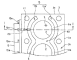
図2は、図1のII−II線におけるエンジン1Aの断面図、すなわちシリンダブロック3を図1の上側から見た図である。なお、図2では、シリンダブロック3の一部のみを示す。シリンダブロック3は、複数のシリンダ2が一列に並ぶようにこれらのシリンダ2を形成する壁部としての内壁6を備えている。図2に示したように内壁6は、各シリンダ2を形成するシリンダ壁6aと、シリンダ壁6a同士を連結する連結部6bとを備えている。連結部6bは、シリンダブロック3の両端に設けられているシリンダ壁6aとシリンダブロック3の外壁3aとの間にも設けられてシリンダ壁6aと外壁3aとを連結している。連結部6bは、シリンダヘッ4と対向するシリンダブロック3のトップデッキ面3bまで設けられている。
2 is a cross-sectional view of the
図3は、図1のIII−III線におけるエンジン1Aの断面図、すなわちシリンダヘッド4を図1の下側から見た図である。なお、図3では、シリンダヘッド4の一部のみを示す。シリンダヘッド4には、シリンダ2に吸気を導くための吸気ポート7及びシリンダ2から排気を排出するための排気ポート8が設けられている。吸気ポート7及び排気ポート8は、各シリンダ2に2つずつ接続されている。また、シリンダヘッド4には、シリンダ2の略中心線上に不図示の点火プラグが配置されるように設けられ、この点火プラグがねじ込まれる点火プラグねじボス9が設けられている。以降、エンジン1Aにおいて吸気ポート7が設けられている側、すなわち図1の右側を吸気側と称し、エンジン1Aにおいて排気ポート8が設けられている側、すなわち図1の左側を排気側と称することがある。なお、図2及び図3においても図1と同様に右側が吸気側、左側が排気側である。
FIG. 3 is a cross-sectional view of the
図1に示したようにエンジン1Aは、冷却水を循環させてエンジン1Aを冷却する冷却装置10を備えている。冷却装置10は、エンジン1Aのクランク軸にて駆動される、若しくはモータで駆動されるウォータポンプ11と、シリンダブロック3及びシリンダヘッド4にて温度が上昇した冷却水と空気とを熱交換して冷却水の温度を低下させるラジエータ12と、シリンダブロック3に設けられるブロック側ウォータジャケット13と、シリンダヘッド4に設けられるヘッド側ウォータジャケット14と、ウォータポンプ11から吐出された冷却水、すなわちブロック側ウォータジャケット13及びヘッド側ウォータジャケット14に供給されるべき冷却水が一時的に貯留されるタンク手段としてのタンク15とを備えている。タンク15は、シリンダブロック3の排気側の側面にネジ15aによってタンク15内の冷却水が外部に漏れないように取り付けられている。ウォータポンプ11及びラジエータ12は、内燃機関に設けられる周知のものと同じものでよいため、詳細な説明は省略する。
As shown in FIG. 1, the
図2に示したようにブロック側ウォータジャケット13は、内壁6と外壁3aとの間に設けられている。ブロック側ウォータジャケット13は、吸気側に設けられるブロック吸気側ウォータジャケット13aと排気側に設けられるブロック排気側ウォータジャケット13bとを備えている。ブロック吸気側ウォータジャケット13aとブロック排気側ウォータジャケット13bとは内壁6を挟んでほぼ対称に設けられている。また、ブロック吸気側ウォータジャケット13a及びブロック排気側ウォータジャケット13bは、そのままの形状でトップデッキ面3bに開口している。
As shown in FIG. 2, the block-
図3に示したようにヘッド側ウォータジャケット14は、シリンダブロック3のトップデッキ面3bと対向する面(以下、下面と称することがある。)4aに開口する複数の開口部16を備えている。図3の想像線はブロック側ウォータジャケット13を示しており、図3に示したように各開口部16はブロック側ウォータジャケット13と対向するように設けられている。なお、シリンダブロック3とシリンダヘッド4との間に設けられるヘッドガスケットにも各開口部16と対向する位置に各開口部16と同じ形状の貫通孔が設けられている。そのため、ブロック側ウォータジャケット13とヘッド側ウォータジャケット14との間で冷却水の移動が可能なように接続されている。ヘッド側ウォータジャケット14は、各シリンダ2の吸気ポート7間に配置される吸気ポート冷却部14a及び各シリンダ2の排気ポート8間に配置される排気ポート冷却部14bを備えている。複数の開口部16のうち排気側に設けられている開口部(以下、排気側開口部と称することがある。)16aは、図1において排気ポート冷却部14bの下方に設けられている。ヘッド側ウォータジャケット14は、点火プラグねじボス9の周囲を介して吸気側と排気側とで接続されている。ヘッド側ウォータジャケット14の内部には、このウォータジャケット14がシリンダ毎に分割されるように、すなわち各シリンダ2の上部に位置する部分同士で冷却水の移動がないようにシリンダ2の並び方向と直交する方向に延びる隔壁(不図示)が設けられている。
As shown in FIG. 3, the head-
図1及び図2に示したようにシリンダブロック3には、タンク15と排気ポート冷却部14bとを接続する第1冷却水通路20と、タンク15とブロック排気側ウォータジャケット13bとを接続する第2冷却水通路21とが設けられている。第1冷却水通路20はシリンダ2毎に設けられている。また、図1に示したように第1冷却水通路20は、その一端が排気側開口部16aと対向するように設けられている。このように第1冷却水通路20を設けることにより、タンク15と排気ポート冷却部14bとを接続することができる。第1冷却水通路20は、例えばシリンダブロック3にパイプを圧入することにより形成される。第2冷却水通路21には、タンク15内の冷却水の圧力が所定の設定圧未満の場合には第2冷却水通路21を全閉し、タンク15内の冷却水の圧力が設定圧以上になると開弁する弁手段としてのワンウェイ開閉弁22が設けられている。設定圧としては、例えばエンジン1Aの暖機時にウォータポンプ11から吐出される冷却水の圧力の上限値が設定される。なお、図1には開弁状態のワンウェイ開閉弁22を示す。
As shown in FIGS. 1 and 2, the
次に、エンジン1Aにおける冷却水の流れを説明する。まず、エンジン1Aの暖機時などタンク15内の冷却水の圧力が設定圧未満の場合を説明する。この場合、ワンウェイ開閉弁22が全閉状態に維持されるため、ウォータポンプ11からタンク15に送られた冷却水の全量が図1及び図2に矢印F1で示したように第1冷却水通路20を介して排気ポート冷却部14bに送られる。その後、この冷却水の一部が排気側開口部16aを介してブロック排気側ウォータジャケット13bに供給される。残りの冷却水は、点火プラグねじボス9の周囲を通過して吸気ポート冷却部14aに送られる。これにより点火プラグねじボス9を冷却することができる。その後、この冷却水は吸気側に設けられた開口部(以下、吸気側開口部と称することがある。)16bを介してブロック吸気側ウォータジャケット13aに供給される。なお、ブロック排気側ウォータジャケット13bに供給された冷却水も、この残りの冷却水と同様にしてブロック吸気側ウォータジャケット13aに移動する。ブロック吸気側ウォータジャケット13aの冷却水はラジエータ12に送られて冷却される。冷却された冷却水は、ウォータポンプ11にて再度タンク15に送られる。以下、同様に冷却水が循環される。
Next, the flow of cooling water in the
一方、タンク15内の冷却水の圧力が設定圧以上の場合は、ワンウェイ開閉弁22が開弁するので、タンク15の冷却水は排気ポート冷却部14bに加えて図2に矢印F2で示したようにブロック排気側ウォータジャケット13bにも供給される。そのため、この冷却水でシリンダブロック3の冷却を促進させることができる。その後、これらの冷却水は上述した場合と同様にブロック吸気側ウォータジャケット13aに移動する。そして、ラジエータ12にて冷却され、ウォータポンプ11によって再度タンク15に送られる。
On the other hand, when the pressure of the cooling water in the
第1の形態のエンジン1Aによれば、ラジエータ12で冷却された冷たい冷却水をタンク15から第1冷却水通路20を介して排気ポート冷却部14bに直接供給することができるので、各シリンダ2の各排気ポート8の冷却をそれぞれ促進させることができる。また、このようにシリンダヘッド4で温度が高くなり易い排気ポート冷却部14bに冷たい冷却水を直接供給できるので、従来よりもウォータポンプ11の吐出能力を下げることができ、これによりエンジン1Aの燃費を改善することができる。さらに、第1冷却水通路20によってヘッド側ウォータジャケット14に導かれた冷却水を点火プラグねじボス9に当ててこの冷却水で点火プラグねじボス9を冷却できるので、点火プラグの冷却が促進される。これによりプレイグニッションの発生を抑制できるので、点火時期を早めてエンジン1Aの性能を向上させることができる。さらに点火プラグの寿命を長くできる。
According to the
エンジン1Aでは、第1冷却水通路20がシリンダ2毎に設けられているとともにヘッド側ウォータジャケット14がシリンダ毎に隔壁で分割されているので、各シリンダ2の上部にそれぞれほぼ同じ量の冷却水を導くことができ、各シリンダ2をほぼ同じ程度に冷却できる。これにより、シリンダ2の上部に設けられる燃焼室の温度差をシリンダ2間で小さくできるので、各シリンダ2における燃焼のばらつきを抑えることができる。そのため、エンジン1Aの性能を向上させたり、エンジン1Aの振動を抑制することができる。また、各シリンダ2から排出される排気の成分のばらつきを抑えることができる。
In the
冷却水の圧力が設定圧未満の場合はブロック排気側ウォータジャケット13bにタンク15から冷却水が直接供給されることを防止できる。そのため、エンジン1Aの暖機を促進させることができる。一方、冷却水の圧力が設定圧以上になるとワンウェイ開閉弁22が開弁するので、ブロック排気側ウォータジャケット13bにもタンク15の冷却水を供給することができる。そのため、シリンダブロック3も適切に冷却することができる。
When the pressure of the cooling water is lower than the set pressure, it is possible to prevent the cooling water from being directly supplied from the
(第2の形態)
次に図4〜図6を参照して本発明の第2の形態に係る内燃機関(エンジン)1Bについて説明する。なお、図4はエンジン1Bの要部を示す図であり、図5のIV−IV線におけるエンジン1Bの断面を示す図である。図5は図4のV−V線におけるエンジン1Bの断面を示す図であり、図6は図4のVI−VI線におけるエンジン1Bの断面を示す図である。すなわち、図5は第1の形態の図2に相当する図であり、図6は第1の形態の図3に相当する図である。この形態において第1の形態と共通の部分には同一の符号を付して説明を省略する。なお、第1の形態では図示を省略したが図4にはヘッドボルトBを示す。
(Second form)
Next, an internal combustion engine (engine) 1B according to a second embodiment of the present invention will be described with reference to FIGS. FIG. 4 is a view showing a main part of the engine 1B, and is a view showing a cross section of the engine 1B taken along line IV-IV in FIG. FIG. 5 is a view showing a cross section of the engine 1B taken along the line VV of FIG. 4, and FIG. 6 is a view showing a cross section of the engine 1B taken along the line VI-VI of FIG. That is, FIG. 5 is a diagram corresponding to FIG. 2 of the first embodiment, and FIG. 6 is a diagram corresponding to FIG. 3 of the first embodiment. In this embodiment, parts common to the first embodiment are denoted by the same reference numerals and description thereof is omitted. Although not shown in the first embodiment, a head bolt B is shown in FIG.
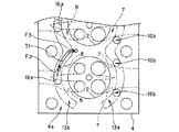
この形態では、図4及び図5に示したようにシリンダブロック3の連結部6bにシリンダ2の並び方向と直交する方向に延びるシリンダ冷却溝30が設けられている。また、図6に示したようにシリンダヘッド4の下面4aには、排気側開口部16aからシリンダ冷却溝30に冷却水を案内するためのガイド溝31が設けられている。シリンダ冷却溝30は、排気側の端部がブロック排気側ウォータジャケット13bと分離され、かつ吸気側の端部がブロック吸気側ウォータジャケット13aと接続されるように設けられている。また、シリンダ冷却溝30はトップデッキ面3bに開口している。シリンダ冷却溝30の深さh1には、例えばシリンダ2のピストンが上死点を通過してからそのピストンがクランク角度にして例えば30°CA(クランク角度を意味する。)など数10°CA移動するまで間にそのピストンのピストントップリングが移動する距離が設定される。シリンダ冷却溝30は、シリンダ2間に配置される各連結部6bにそれぞれ設けられている。ガイド溝31は、ヘッド側ウォータジャケット14aの冷却水が排気側開口部16aからシリンダ冷却溝30の排気側の端部に導かれるように設けられている。また、ガイド溝31は、下面4aのうちシリンダ2と対向する部分は避けて設けられている。ガイド溝31は、各シリンダ冷却溝30にそれぞれ冷却水を導入可能なように各シリンダ冷却溝30に対応して設けられている。
In this embodiment, as shown in FIGS. 4 and 5, the
第2の形態のエンジン1Bによれば、図4及び図6に矢印F3で示したように第1冷却水通路20からのヘッド側ウォータジャケット14の冷却水の一部を排気側開口部16aからシリンダ冷却溝30にガイド溝31にて導くことができる。シリンダ冷却溝30に導かれた冷却水は、図4及び図5に矢印F4で示したようにシリンダ冷却溝30内を通過してブロック吸気側ウォータジャケット13aに排出される。第1の形態で説明したように第1冷却水通路20の一端は排気側開口部16aと対向するように設けられている。そのため、シリンダ冷却溝30には第1冷却水通路20を通ってタンク15から供給された冷たい冷却水の一部を導入することができる。そのため、この冷却水によって連結部6bをそれぞれ冷却することができる。この場合、連結部6bの冷却を促進させることができるので、シリンダ2の熱変形を抑制できる。これによりピストンリングの張力を低減できるので、ピストンが摺動するときの抵抗を低減できる。また、冷却溝30はトップデッキ面3bに開口しているため、各連結部6bのうちトップデッキ面3bを形成する部分の温度を低減できる。そのため、これらの部分の材料硬度の低下を抑制できる。さらに、これらの部分がヘッドガスケット(不図示)シールビード部の高面圧部により、トップデッキ面3bから陥没することを抑制できるので、シリンダ2内の燃焼ガスがシリンダブロック3とシリンダヘッド4との間から抜けることを抑制し、エンジン1Bの出力低下を抑制できる。
According to the engine 1B of the second embodiment, as shown by the arrow F3 in FIGS. 4 and 6, a part of the cooling water of the head
上述したように冷却水の圧力が設定圧未満の場合はワンウェイ開閉弁22が全閉になり、冷却水の全量が第1冷却水通路20に導かれる。そのため、冷却水の流量が少量でも冷却水をシリンダ冷却溝30に導くことができる。従って、エンジン1Bの信頼性を向上させることができる。また、シリンダ冷却溝30の冷却水によって各シリンダ2の温度を低減できるので、シリンダ2の内面に付着しているオイルの蒸発を減少させ、オイルの消費量を低減できる。また、オイルの蒸発量を減少させることにより、排気エミッションを改善できる。
As described above, when the pressure of the cooling water is lower than the set pressure, the one-way opening / closing
(第3の形態)
図7〜図9を参照して本発明の第3の形態に係る内燃機関(エンジン)1Cについて説明する。なお、図7はエンジン1Cの要部を示す図であり、図8のVII−VII線におけるエンジン1Cの断面を示す図である。図8は図7のVIII−VIII線におけるエンジン1Cの断面を示す図であり、図9は図7のIX−IX線におけるエンジン1Cの断面を示す図である。なお、この形態において上述した各形態と共通の部分には同一の符号を付して説明を省略する。
(Third form)
An internal combustion engine (engine) 1C according to a third embodiment of the present invention will be described with reference to FIGS. FIG. 7 is a view showing a main part of the
この形態では、図7及び図8に示したようにシリンダブロック3の連結部6bにシリンダ2の並び方向と直交する方向に延びる冷却水流通溝40が設けられている。この冷却水流通溝40は、排気側の端部がブロック排気側ウォータジャケット13bと分離されるとともに吸気側の端部もブロック吸気側ウォータジャケット13aと分離されるように設けられている。冷却水流通溝40はトップデッキ面3bに開口している。冷却水流通溝40の深さh2には、シリンダ冷却溝30と同じ値が設定される。冷却水流通溝40は、シリンダ2間に配置される各連結部6bにそれぞれ設けられている。図7に示したように冷却水流通溝40は、吸気側と排気側とで断面形状が各シリンダ2の中心を結ぶ線Cを挟んで対称になるように設けられている。
In this embodiment, as shown in FIGS. 7 and 8, a cooling
この形態では、図7及び図9に示したようにシリンダヘッド4の下面4aに冷却水流通溝40の吸気側の端部とブロック吸気側ウォータジャケット13aとを接続する出口溝41が設けられている。出口溝41は、冷却水流通溝40に対応して冷却水流通溝40と同数設けられている。このように出口溝41を設けることにより、図7に矢印F5で示したように冷却水流通溝40の冷却水をブロック吸気側ウォータジャケット13aに排出することができる。
In this embodiment, as shown in FIGS. 7 and 9, the
第3の形態のエンジン1Cでは、連結部6bに設けられる冷却水流通溝40が各シリンダ2の中心を結ぶ線Cを挟んで吸気側と排気側とで形状が対称になるように設けられているので、連結部6bの吸気側と排気側とをそれぞれ同様に冷却できる。この場合、シリンダ2の吸気側と排気側とがほぼ同じように熱で変形し、温度低減により、熱変形によるシリンダ2の形状の変化を抑制することができる。そのため、シリンダ2の内面へのピストンリングの追従性を向上させることができる。従って、ピストンリングの張力を低減できる。また、これにより、ピストンリングの摺動抵抗を低減させることができるので、エンジン1Cの燃費を改善できる。
In the
本発明は、上述した各形態に限定されることなく、種々の形態にて実施することができる。例えば、本発明が適用される内燃機関はディーゼル機関であってもよい。また、本発明が適用される内燃機関は、V型内燃機関、水平対向式内燃機関でもよい。内燃機関の気筒数は4気筒に限定されず、1つ以上の気筒を有する内燃機関であればよい。 This invention is not limited to each form mentioned above, It can implement with a various form. For example, the internal combustion engine to which the present invention is applied may be a diesel engine. The internal combustion engine to which the present invention is applied may be a V-type internal combustion engine or a horizontally opposed internal combustion engine. The number of cylinders of the internal combustion engine is not limited to four, and may be any internal combustion engine having one or more cylinders.
1A、1B、1C 内燃機関
2 シリンダ
3 シリンダブロック
3b トップデッキ面
4 シリンダヘッド
6 内壁(壁部)
6b 連結部
8 排気ポート
13 ブロック側ウォータジャケット
14 ヘッド側ウォータジャケット
14b 排気ポート冷却部
15 タンク(タンク手段)
20 第1冷却水通路
21 第2冷却水通路
22 ワンウェイ開閉弁(弁手段)
30 冷却溝
31 ガイド溝
40 冷却水流通溝
41 出口溝
1A, 1B, 1C
20 1st cooling
30
Claims (4)
前記シリンダブロックの側面に設けられ、前記ヘッド側ウォータジャケット及び前記ブロック側ウォータジャケットに供給されるべき冷却水が貯留されるタンク手段と、前記タンク手段と前記排気ポート冷却部とを接続する第1冷却水通路と、前記タンク手段と前記ブロック側ウォータジャケットとを接続する第2冷却水通路と、前記第2冷却水通路に設けられ、前記タンク手段内の冷却水の圧力が所定の設定圧未満の場合は前記第2冷却水通路を全閉し、前記タンク手段内の冷却水の圧力が前記設定圧以上になると開弁する弁手段と、を備えていることを特徴とする内燃機関。 A head formed in the cylinder head, having a cylinder head in which each exhaust port is formed so that the two exhaust ports are connected to a common cylinder, and an exhaust port cooling part provided between the two exhaust ports In an internal combustion engine comprising: a side water jacket; and a block side water jacket formed to communicate with the head side water jacket in a cylinder block to which the cylinder head is fixed.
A tank means provided on a side surface of the cylinder block for storing the head-side water jacket and the coolant to be supplied to the block-side water jacket, and a first connecting the tank means and the exhaust port cooling section. A cooling water passage, a second cooling water passage connecting the tank means and the block-side water jacket, and the second cooling water passage are provided, and the pressure of the cooling water in the tank means is less than a predetermined set pressure. In this case, an internal combustion engine comprising: valve means that fully closes the second cooling water passage and opens when the pressure of the cooling water in the tank means exceeds the set pressure.
前記第1冷却水通路はシリンダ毎に設けられている請求項1に記載の内燃機関。 The internal combustion engine includes a plurality of cylinders,
The internal combustion engine according to claim 1, wherein the first cooling water passage is provided for each cylinder.
前記壁部のうちシリンダ間に配置される連結部には、前記シリンダヘッドと対向する前記シリンダブロックのトップデッキ面に開口するとともに前記複数のシリンダの並び方向と交差する方向に延び、かつ前記内燃機関において前記排気ポートが設けられる側に配置される一方の端部が前記ブロック側ウォータジャケットと分離されるとともに他方の端部が前記ブロック側ウォータジャケットと接続される冷却溝が設けられ、
前記シリンダヘッドには、前記排気ポート冷却部の冷却水の一部を前記冷却溝の前記一方の端部に案内するガイド溝が設けられている請求項2に記載の内燃機関。 The cylinder block includes a common wall portion around which the block-side water jacket is provided to form the plurality of cylinders,
A connecting portion disposed between the cylinders among the wall portions opens in a top deck surface of the cylinder block facing the cylinder head and extends in a direction intersecting with an arrangement direction of the plurality of cylinders, and the internal combustion engine In the engine, one end portion disposed on the side where the exhaust port is provided is separated from the block-side water jacket, and the other end portion is provided with a cooling groove connected to the block-side water jacket,
The internal combustion engine according to claim 2, wherein the cylinder head is provided with a guide groove that guides a part of the cooling water of the exhaust port cooling unit to the one end of the cooling groove.
前記壁部のうちシリンダ間に配置される連結部には、前記シリンダヘッドと対向する前記シリンダブロックのトップデッキ面に開口するとともに前記複数のシリンダの並び方向と交差する方向に延び、かつ前記ブロック側ウォータジャケットとは分離されるともに前記複数のシリンダの中心を結ぶ線を挟んで前記シリンダブロックの一方の側と他方の側とで形状が対称になるように形成される冷却水流通溝が設けられ、
前記シリンダヘッドには、前記排気ポート冷却部の冷却水の一部を前記冷却水流通溝の端部のうち前記内燃機関において前記排気ポートが設けられる側に配置される一方の端部に案内するガイド溝と、前記冷却水流通溝の他方の端部と前記ブロック側ウォータジャケットとを接続する出口溝と、が設けられている請求項2に記載の内燃機関。 The cylinder block includes a common wall portion around which the block-side water jacket is provided to form the plurality of cylinders,
The connecting portion disposed between the cylinders among the wall portions opens in a top deck surface of the cylinder block facing the cylinder head and extends in a direction intersecting with an arrangement direction of the plurality of cylinders, and the block A cooling water circulation groove is provided which is separated from the side water jacket and is formed to have a symmetrical shape on one side and the other side of the cylinder block across a line connecting the centers of the plurality of cylinders. And
In the cylinder head, a part of the cooling water of the exhaust port cooling part is guided to one end part arranged on the side where the exhaust port is provided in the internal combustion engine among the end parts of the cooling water circulation groove. The internal combustion engine according to claim 2, wherein a guide groove and an outlet groove that connects the other end of the cooling water circulation groove and the block-side water jacket are provided.
Priority Applications (1)
| Application Number | Priority Date | Filing Date | Title |
|---|---|---|---|
| JP2008108066A JP2009257227A (en) | 2008-04-17 | 2008-04-17 | Internal combustion engine |
Applications Claiming Priority (1)
| Application Number | Priority Date | Filing Date | Title |
|---|---|---|---|
| JP2008108066A JP2009257227A (en) | 2008-04-17 | 2008-04-17 | Internal combustion engine |
Publications (1)
| Publication Number | Publication Date |
|---|---|
| JP2009257227A true JP2009257227A (en) | 2009-11-05 |
Family
ID=41384947
Family Applications (1)
| Application Number | Title | Priority Date | Filing Date |
|---|---|---|---|
| JP2008108066A Pending JP2009257227A (en) | 2008-04-17 | 2008-04-17 | Internal combustion engine |
Country Status (1)
| Country | Link |
|---|---|
| JP (1) | JP2009257227A (en) |
Cited By (7)
| Publication number | Priority date | Publication date | Assignee | Title |
|---|---|---|---|---|
| WO2011157417A1 (en) * | 2010-06-18 | 2011-12-22 | Audi Ag | Internal combustion engine comprising a coolant collector for shut-down cooling and/or warm-up cooling |
| DE102011122280A1 (en) * | 2011-12-23 | 2013-06-27 | Audi Ag | Combustion engine, has coolant duct branched from coolant distributor, and locking unit attached to coolant duct and releasing fluid connection through coolant duct only when reaching or exceeding minimum pressure by coolant pressure |
| WO2014065109A1 (en) * | 2012-10-24 | 2014-05-01 | 日産自動車株式会社 | Cylinder block of v-type internal-combustion engine |
| JP2014084717A (en) * | 2012-10-19 | 2014-05-12 | Toyota Motor Corp | Cooling device for internal combustion engine |
| JP2014092031A (en) * | 2012-10-31 | 2014-05-19 | Toyota Motor Corp | Cooling path switching device of internal combustion engine |
| JP2015190350A (en) * | 2014-03-27 | 2015-11-02 | ダイハツ工業株式会社 | Internal combustion engine cylinder head |
| WO2022145897A1 (en) * | 2020-12-30 | 2022-07-07 | 현대두산인프라코어 주식회사 | Cylinder block and engine comprising same |
-
2008
- 2008-04-17 JP JP2008108066A patent/JP2009257227A/en active Pending
Cited By (12)
| Publication number | Priority date | Publication date | Assignee | Title |
|---|---|---|---|---|
| WO2011157417A1 (en) * | 2010-06-18 | 2011-12-22 | Audi Ag | Internal combustion engine comprising a coolant collector for shut-down cooling and/or warm-up cooling |
| CN102947574A (en) * | 2010-06-18 | 2013-02-27 | 奥迪股份公司 | Internal combustion engine comprising a coolant collector for shut-down cooling and/or warm-up cooling |
| JP2013528743A (en) * | 2010-06-18 | 2013-07-11 | アウディ アクチェンゲゼルシャフト | INTERNAL COMBUSTION ENGINE HAVING COOLANT COLLECTION TUBE FOR COOLING DURING COLD OR OPERATION |
| US9004021B2 (en) | 2010-06-18 | 2015-04-14 | Audi Ag | Combustion engine with coolant collector for shut-down cooling and/or warm-up cooling |
| DE102010024319B4 (en) * | 2010-06-18 | 2016-03-03 | Audi Ag | Internal combustion engine with coolant busbar for after-running and / or warm-up cooling |
| DE102011122280A1 (en) * | 2011-12-23 | 2013-06-27 | Audi Ag | Combustion engine, has coolant duct branched from coolant distributor, and locking unit attached to coolant duct and releasing fluid connection through coolant duct only when reaching or exceeding minimum pressure by coolant pressure |
| DE102011122280B4 (en) * | 2011-12-23 | 2020-02-13 | Audi Ag | Internal combustion engine with a coolant distributor and method for operating the same |
| JP2014084717A (en) * | 2012-10-19 | 2014-05-12 | Toyota Motor Corp | Cooling device for internal combustion engine |
| WO2014065109A1 (en) * | 2012-10-24 | 2014-05-01 | 日産自動車株式会社 | Cylinder block of v-type internal-combustion engine |
| JP2014092031A (en) * | 2012-10-31 | 2014-05-19 | Toyota Motor Corp | Cooling path switching device of internal combustion engine |
| JP2015190350A (en) * | 2014-03-27 | 2015-11-02 | ダイハツ工業株式会社 | Internal combustion engine cylinder head |
| WO2022145897A1 (en) * | 2020-12-30 | 2022-07-07 | 현대두산인프라코어 주식회사 | Cylinder block and engine comprising same |
Similar Documents
| Publication | Publication Date | Title |
|---|---|---|
| KR101639543B1 (en) | Internal combustion engine | |
| US10787952B2 (en) | Exhaust side block insert, cylinder block assembly including the same, and heat management system of engine including the same | |
| JP2009257227A (en) | Internal combustion engine | |
| JP6036668B2 (en) | Multi-cylinder engine cooling structure | |
| JP6079594B2 (en) | Multi-cylinder engine cooling structure | |
| JP4085253B2 (en) | Engine cooling system | |
| US7520257B2 (en) | Engine cylinder head | |
| EP3034846A1 (en) | Cylinder block | |
| JP2011021508A (en) | Cooling structure of internal combustion engine | |
| JP2003201842A (en) | Cooling device of engine | |
| US11092109B2 (en) | Block insert and cylinder structure of vehicle engine including the same | |
| JP4998339B2 (en) | Cooling device for internal combustion engine | |
| JP2010084581A (en) | Structure for cooling egr gas | |
| US10330042B2 (en) | Water jacket for cylinder head | |
| CN109209596B (en) | Water-cooled engine | |
| JP2715307B2 (en) | Liquid-cooled engine cooling structure | |
| CN106870190B (en) | Water jacket apparatus for engine | |
| JP4411969B2 (en) | Engine cooling system | |
| JP4496844B2 (en) | Heat shield engine | |
| EP3623596B1 (en) | Internal combustion engine body | |
| JP4623581B2 (en) | Cylinder head in liquid-cooled internal combustion engine | |
| JP2005120945A (en) | Cooling structure of cylinder block | |
| JP4407425B2 (en) | Engine cooling system | |
| JP2009236087A (en) | Internal combustion engine | |
| JP2008231934A (en) | Cylinder head in overhead four-valve type multiple cylinder internal combustion engine |