JP2009255149A - Method for manufacturing non-ferrous metal formed body - Google Patents
Method for manufacturing non-ferrous metal formed body Download PDFInfo
- Publication number
- JP2009255149A JP2009255149A JP2008109491A JP2008109491A JP2009255149A JP 2009255149 A JP2009255149 A JP 2009255149A JP 2008109491 A JP2008109491 A JP 2008109491A JP 2008109491 A JP2008109491 A JP 2008109491A JP 2009255149 A JP2009255149 A JP 2009255149A
- Authority
- JP
- Japan
- Prior art keywords
- small convex
- mold
- preform
- convex portion
- manufacturing
- Prior art date
- Legal status (The legal status is an assumption and is not a legal conclusion. Google has not performed a legal analysis and makes no representation as to the accuracy of the status listed.)
- Pending
Links
Images


Classifications
-
- B—PERFORMING OPERATIONS; TRANSPORTING
- B21—MECHANICAL METAL-WORKING WITHOUT ESSENTIALLY REMOVING MATERIAL; PUNCHING METAL
- B21K—MAKING FORGED OR PRESSED METAL PRODUCTS, e.g. HORSE-SHOES, RIVETS, BOLTS OR WHEELS
- B21K23/00—Making other articles
Abstract
Description
本発明は、マグネシウム、亜鉛、アルミニウム等を始めとする各種の非鉄金属からなる成形体の製造方法に関する。 The present invention relates to a method for producing a molded body made of various non-ferrous metals such as magnesium, zinc and aluminum.
マグネシウムやマグネシウム合金(以下、これらを総称してマグネシウム素材という。)は、軽量でかつ剛性に優れているので、自動車などの輸送機器分野やノート型のパーソナルコンピュータなどの電子機器の筐体等の素材として利用されている。マグネシウム素材の立体的な加工には、主としてダイカスト、チクソモールディングなどの鋳造や、鍛造などの方法が用いられている。しかし、マグネシウム素材は展延性に劣るので、複雑で高精度の立体形状を形成することは容易でない。そのような複雑な立体形状を鍛造によって得ようとする場合には、過大な成形荷重が必要となり、それに起因して金型への負荷が大きくなり、金型が劣化しやすく寿命が短くなってしまう。また、そのような加工を行うには高価な専用機の導入が必要となり、設備コストの増大の原因となる。 Magnesium and magnesium alloys (hereinafter collectively referred to as magnesium materials) are lightweight and excellent in rigidity, so they are used in the field of transportation equipment such as automobiles and the housings of electronic devices such as notebook personal computers. It is used as a material. For three-dimensional processing of magnesium material, methods such as casting such as die casting and thixo molding and forging are mainly used. However, since magnesium material is inferior in spreadability, it is not easy to form a complicated and highly accurate three-dimensional shape. When trying to obtain such a complicated three-dimensional shape by forging, an excessive molding load is required, resulting in an increase in the load on the mold, which tends to deteriorate the mold and shorten the service life. End up. Further, in order to perform such processing, it is necessary to introduce an expensive dedicated machine, which causes an increase in equipment cost.
ところで、電子機器のうち高級機種の外装部品や内部部品などにはマグネシウム素材を原料としたプレス加工による成形品がしばしば使用される。そのような成形品においては、プレス加工でボスやリブなどの立体形状を成形することが容易でないので、別途成形されたボスやリブを組み立てて利用しているのが現状である。しかし、経済性の観点から、マグネシウムを素材としたプレス加工品にボスやリブを一体に成形することが望まれている。 By the way, a molded product by press working using a magnesium material as a raw material is often used for exterior parts and internal parts of high-end models among electronic devices. In such a molded product, since it is not easy to form a three-dimensional shape such as a boss or a rib by pressing, it is currently used by assembling a separately formed boss or rib. However, from the viewpoint of economy, it is desired to form bosses and ribs integrally with a pressed product made of magnesium.
この観点から、特許文献1においては、マグネシウム合金板材に、その厚さ方向の荷重を印加して、凸部を形成する工程を有するマグネシウム合金部品の製造方法において、凸部を形成しようとする領域近傍における合金材料の流動性Aを、その裏面近傍における合金材料の流動性Bよりも大きくなるように制御する方法が提案されている。この方法においては、凸部を形成しようとする領域又はその領域を加工する金型表面領域に、凸部を形成しようとする領域の摩擦係数をその裏面における摩擦係数よりも下げるための表面処理を施すことにより、流動性Aを流動性Bよりも大きくしている。 From this point of view, in Patent Document 1, in a manufacturing method of a magnesium alloy component having a step of forming a convex portion by applying a load in the thickness direction to the magnesium alloy sheet, a region where the convex portion is to be formed. A method has been proposed in which the fluidity A of the alloy material in the vicinity is controlled to be larger than the fluidity B of the alloy material in the vicinity of the back surface. In this method, the surface treatment for lowering the friction coefficient of the region where the convex portion is to be formed on the region where the convex portion is to be formed or the mold surface region where the region is to be processed is lower than the friction coefficient on the back surface. By applying, the fluidity A is made larger than the fluidity B.
また、特許文献2においては、マグネシウム平板を鍛造してその各面に子凸部と裏補助凸部を形成して成形素材を得る一次加工と、一次加工で得られた成形素材を鍛造して、目的とする凸部を前記の子凸部及び裏補助凸部から形成する仕上げ加工とを行う方法が提案されている。 Moreover, in patent document 2, forging the shaping | molding raw material obtained by the primary process which forges a magnesium flat plate, forms a sub convex part and a back auxiliary convex part in each surface, and obtains a shaping | molding material, and a primary process. There has been proposed a method of performing a finishing process in which a target convex portion is formed from the above-mentioned sub convex portion and back auxiliary convex portion.
しかし、特許文献1に記載の方法では、摩擦係数を低減させるための処理を、金型の表面に成形のたびに行う必要があるので、生産性の点で有利とは言えない。特許文献2に記載の方法では、目的物を得るために一次加工及び仕上げ加工の2つの工程が必要となり、更に一次加工及び仕上げ加工に対応した金型をそれぞれ用意しなければならないので、やはり生産性の点で有利とは言えない。 However, the method described in Patent Document 1 is not advantageous in terms of productivity because the process for reducing the friction coefficient needs to be performed on the surface of the mold every time it is molded. In the method described in Patent Document 2, two steps of primary processing and finishing are required to obtain an object, and further, a mold corresponding to the primary processing and finishing must be prepared. It is not advantageous in terms of sex.
したがって本発明の目的は、前述した従来技術が有する種々の欠点を解消し得る非鉄金属成形体の製造方法を提供することにある。 Accordingly, an object of the present invention is to provide a method for producing a non-ferrous metal molded body that can eliminate the various drawbacks of the above-described prior art.
本発明は、凹部を有する金型を用いて非鉄金属材料を塑性加工して、該凹部に対応する形状の凸部を有する成形体を成形する非鉄金属成形体の製造方法において、
略板状体からなり、該板状体の少なくとも一方の面のうち前記凹部に対応する位置に小凸部を有する予備成形体を鋳造法によって成形し、
前記予備成形体の平面視での前記小凸部の形成位置が前記金型の前記凹部に対向するように、該予備成形体を該金型に設置し、該金型によって該予備成形体を塑性加工して、該小凸部を該凹部内に塑性流動させ、該凹部に対応する形状の凸部を有する成形体を成形することを特徴とする非鉄金属成形体の製造方法を提供するものである。
The present invention is a method for producing a non-ferrous metal molded body in which a non-ferrous metal material is plastically processed using a mold having a recess, and a molded body having a convex portion having a shape corresponding to the recess is formed.
A substantially plate-like body, and molding a preform having a small convex portion at a position corresponding to the concave portion of at least one surface of the plate-like body by a casting method;
The preform is placed in the mold so that the formation position of the small convex portion in plan view of the preform faces the recess of the mold, and the preform is moved by the mold. Provided is a method for producing a non-ferrous metal molded body, which is plastically processed to plastically flow the small convex portion into the concave portion and to form a molded body having a convex portion having a shape corresponding to the concave portion. It is.
本発明によれば、金型に過大な負荷を与えることなく複雑な立体形状を有する成形体を容易に製造することができる。 ADVANTAGE OF THE INVENTION According to this invention, the molded object which has a complicated solid shape can be manufactured easily, without giving an excessive load to a metal mold | die.
以下本発明を、その好ましい実施形態に基づき図面を参照しながら説明する。本発明の製造方法は大別して(イ)鋳造工程と、(ロ)塑性加工工程とに大別される。以下、それぞれの工程について説明する。 The present invention will be described below based on preferred embodiments with reference to the drawings. The production method of the present invention is roughly classified into (a) a casting process and (b) a plastic working process. Hereinafter, each process will be described.
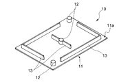
図1には、本発明の製造方法で製造された成形体の一例が示されている。成形体10は非鉄金属材料からなる。成形体10は、板状体からなる基板11の第1の面11aに立設されたボス12及びリブ13を有している。ボス12及びリブ13は、基板11と一体構造となっている。基板11の第2の面(図示せず)は平坦でかつ平滑になっている。基板11の第1の面11aを基準とするボス12及びリブ13の高さは、基板11の厚みの例えば2〜20倍程度になっている。このような立体性の高い形状を有する成形体10を、図2に示す予備成形体20から成形する。
FIG. 1 shows an example of a molded body produced by the production method of the present invention. The molded
図2に示す予備成形体20は鋳造法によって成形される。鋳造法としては、公知の方法、例えばダイカスト鋳造法やチクソモールディング法などを特に制限なく用いることができる。生産性や経済性の観点からは、ダイカスト鋳造法を採用することが好ましい。ダイカスト鋳造法としては、主としてホットチャンバーダイカスト機を用いる方法と、コールドチャンバーダイカスト機を用いる方法とが知られている。例えば、マグネシウム系や亜鉛系の非鉄金属材料を用いる場合にはホットチャンバーダイカスト法が有利であり、アルミニウム系の非鉄金属材料を用いる場合にはコールドチャンバーダイカスト法が有利である。どちらの方法を実施する場合においても、その条件に特に制限はなく、従来公知の条件を適切に選択すればよい。そのような条件は、当業者において良く知られているところであり、本明細書において特に詳述するまでもない。本発明においてどちらの方法を採用するかは、使用する非鉄金属材料の種類に応じて適切に決定される。どちらのダイカスト鋳造法を採用するかは、本発明において臨界的ではない。
The
鋳造法によって成形される予備成形体20は、矩形の略板状体からなる平板部21を有している。平板部21は、第1の面21aと、これと反対側に位置する第2の面(図2では図示せず)とを有している。第1の面21aは、後述する塑性加工工程において、凹部を有する金型と対向する面である。
The
平板部21における第1の面21aの上には略ドーム状の立体形状をした小凸部(以下、第1小凸部22aという。)が形成されている。また、第1の面21a上には、略半円柱を横臥状態にした立体形状の小凸部(以下、第2小凸部22bという。)も形成されている。第1小凸部22a及び第2小凸部22bは、平板部21と一体構造となっている。なお、以下の説明において、第1小凸部22a及び第2小凸部22bを総称して小凸部と呼ぶときは、これを符号22で示す。
On the
第1小凸部22aは、矩形の平板部21における4箇所の隅部のうちの対角線上に位置する2箇所の隅部に形成されている。また第1小凸部22aは、平板部21における中心部にも形成されている。一方、第2小凸部22bは、矩形の平板部21における4箇所の隅部のうち第1小凸部22aが形成されていない残り2箇所の隅部に形成されている。これら2箇所の隅部においては、2個で一対をなす第2小凸部22bが、平板部21の長辺及び短辺に沿って、かつ90度の角をなすように配置されている。また、第2小凸部22bは、平板部21の中央部近傍に一対配置されている。一対の第2小凸部22bは、平板部21の中央部に配置された第1小凸部22aを挟んで位置し、各第2小凸部22bの長手方向が、平板部21の短辺方向と一致するように配置されている。
The first
上述した第1小凸部22a及び第2小凸部22bは、後述する塑性加工工程において、予備成形体20が凹部を有する金型に設置された状態で、該金型の凹部に対向する位置に形成されている。
The first
図2には示していないが、同図に示す予備成形体20においては、第1の面21aと反対側に位置する第2の面にも小凸部が形成されている。各面に形成された小凸部は、予備成形体20の平面視において同位置に存在している。尤も、各面に小凸部を形成する場合、その配置位置は同位置に限らない。具体的には、予備成形体20の平面視での小凸部の形成位置が、塑性加工工程における金型の凹部に対向する位置であれば、各面に配置される小凸部の位置は任意に選択できる。例えば、図2に示す予備成形体20において、中央部に位置する第1小凸部22a及び2つの第2小凸部22bを第1の面21a側にのみ形成し、かつ四隅に位置する第1小凸部22a及び第2小凸部22bを第2の面側にのみ形成することができる。要するに、予備成形体20の第1の面21aに小凸部22a,22bを形成し、第2の面における同位置には小凸部を形成せず、かつ予備成形体20の第2の面に小凸部を形成し、第1の面21aにおける同位置には小凸部22a,22bを形成しないようにすることができる。
Although not shown in FIG. 2, in the
第1の面21aに形成された小凸部22a,22bと、第2の面に形成された小凸部とは、同一の形状でもよく、あるいは異なる形状でもよい。ここで言う形状とは、小凸部の立体形状のことである。したがって、例えば2つの小凸部が平面視においては同一の輪郭を有する場合であっても、両者の高さ(厚さ)が異なる場合には、それら2つの小凸部は異なる形状であると言う。
The small
以上の構造を有する予備成形体20を塑性加工工程に付して、目的とする立体形状を有する成形体を製造する。図3(a)ないし(c)には、塑性加工の手順を順次示す工程図が示されている。これらの図においては、金型30a,30b及び予備成形体20の断面形状が示されている。なお、図3(a)ないし(c)においては、理解の助けとするために、予備成形体20の断面形状を簡略化して示している。したがって、この断面形状は、図2に示す予備成形体20と完全に一致していない。同様に、金型30a,30bの断面形状も簡略化して示している。
The preformed
先ず、図3(a)に示すように、第1の金型30a(ダイ)及び第2の金型30b(パンチ)を備えた成形装置の型開状態において、両金型30a,30b間に予備成形体20を設置する。第1の金型30aのパーティング面には凹部(キャビティ)31が形成されている。凹部31の形状は、目的とする成形体10(図1参照)における凸部、つまりボス12やリブ13と相補形状になっている。一方、第2の金型30bのパーティング面は平滑になっている。
First, as shown in FIG. 3A, in the mold open state of a molding apparatus provided with a
金型30a,30bの型開状態において、予備成形体20は、その第1の面21aが、凹部31を有する金型である第1の金型30aと対向し、第2の面21bが、平滑な金型である第2の金型30bと対向するように、両金型間に設置される。予備成形体20が両金型間に設置された状態においては、予備成形体20の平面視での小凸部22の形成位置が、第1の金型30aの凹部31に対向している。
In the mold open state of the
次に、プレス加工装置を動作させて型閉動作を行うが、それに先立ち、図3(b)に示すように、第1の金型30aの凹部31に対向する小凸部22の一部(先端部)又は該小凸部の全体を該凹部31に嵌挿させて、予備成形体20の位置決め操作を行うことが好ましい。この操作によって、予備成形体20の設置ずれを容易に防止することができる。小凸部22を凹部31に嵌挿させる程度は、予備成形体20の位置ずれが起こらない程度であればよい。その程度は、小凸部22及び凹部31それぞれの寸法や体積等に応じて適宜決定することができる。予備成形体20の位置決め完了後、図3(c)に示すように型閉動作を行い、予備成形体20をプレスする。この操作によって予備成形体20は、加圧されて材料の塑性流動が生じプレス鍛造される。その結果、第1の金型30aの凹部31に対向している小凸部を構成する材料が、凹部31内に流動して該凹部31内を満たすようになる。また、該小凸部と反対側に位置する小凸部の構成材料も流動して凹部31内を満たすようになる。プレス鍛造は、予備成形体20の構成材料である非鉄金属材料の種類に応じ、温間鍛造、熱間鍛造又は冷間鍛造でもよい。
Next, the press working apparatus is operated to perform the mold closing operation. Prior to that, as shown in FIG. 3B, a part of the small convex portion 22 (as shown in FIG. 3B) facing the
プレス鍛造の条件は、目的とする成形体10(図1参照)の形状や材料の種類に応じて適切に決定することができる。例えば成形荷重は一般に20〜1000N/mm2、特に400〜600N/mm2とすることができる。成形速度は一般に1〜200mm/秒、特に5〜20mm/秒とすることができる。下死点での停止時間は20秒以下、特に5〜10秒とすることができる。成形温度は、室温〜400℃、特に200〜350℃とすることができる。非鉄金属材料がマグネシウム系材料である場合には、塑性加工の温度を100〜400℃、特に200〜350℃とすることが好ましい。 The conditions for press forging can be appropriately determined according to the shape of the target molded body 10 (see FIG. 1) and the type of material. For example, the molding load can generally be 20 to 1000 N / mm 2 , in particular 400 to 600 N / mm 2 . The molding speed can generally be from 1 to 200 mm / second, in particular from 5 to 20 mm / second. The stop time at the bottom dead center can be 20 seconds or less, particularly 5 to 10 seconds. The molding temperature can be room temperature to 400 ° C, particularly 200 to 350 ° C. When the non-ferrous metal material is a magnesium-based material, the temperature of plastic working is preferably 100 to 400 ° C, particularly 200 to 350 ° C.
予備成形体22に形成されている小凸部20の大きさは、プレス鍛造によって成形される成形体10の仕上がり状態の良否に影響を及ぼす。この観点から、予備成形体20における小凸部22の体積を、対応する金型30aの凹部31の体積よりも大きくすることが好ましい。具体的には、小凸部22の体積は、それに対応する凹部31の体積の30〜200%、特に110〜190%であることが好ましい。予備成形体20の各面における同位置に小凸部22が形成されている場合、小凸部22の体積とは、各面に形成されている小凸部22の合計の体積のことである。
The size of the
予備成形体20の同位置に小凸部22が形成されている場合、各小凸部22の形状を制御することで、成形体10の仕上がり状態を一層良好にすることができる。例えば、予備成形体20の面のうち、金型30aの凹部31に対向する面と反対側の面に形成された裏側小凸部と、平面視において該裏側小凸部と同位置に形成された表側小凸部との体積の比を適切に設定することが好ましい。具体的には、表側小凸部と裏側小凸部との体積の比に関し、裏側小凸部の体積を、表側小凸部の体積の0.5〜5倍、特に1〜4倍に設定することが好ましい。裏側小凸部及び表側小凸部の体積とは、予備成形体20における平板部21の平面を基準面として、該基準面から突出している部位の体積のことである。
When the small
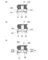
塑性加工工程に付される予備成形体20においては、各小凸部22a及び22bは、その縦断面形状が、角部を有さない滑らかな形状であることが好ましい。例えば略半円形状であるか、又は略半楕円形状等の丸みを帯びた角部のない形状であることが好ましい。各小凸部22a及び22bがこのような形状を有していることで、金型からの離型性が良好になる。その結果、金型の劣化が起こりにくくなり、金型の寿命を延ばすことができるという利点がある。また、離型性が良好であることは、離型剤の使用量の低減にもつながり、それによって製造経費を削減することができ、また環境負荷の増大を防止できる。角部を有さないとは、小凸部を縦断面視して得られる輪郭線において、2本の直線が交わる部分が存在しないことを言う。角部を有しない形状として、略半円形状や略半楕円形状以外の形状を採用することに何ら差し支えはない。例えば、図4(a)に示すように、小凸部22を縦断面視した状態で、その側面221が平板部21の表面からほぼ直角に起立しており、かつ該側面221が、平板部21の表面とほぼ平行になっている上面222と、曲線状に滑らかに連接している形状とすることができる。また図4(b)に示すように、小凸部22を縦断面視した状態で、略台形状をなし、かつ側面221が上面222と、曲線状に滑らかに連接している形状とすることができる。更に、図4(c)に示すように、小凸部22を縦断面視した状態で、平板部21上に位置する台形部223と、該台形部223上に位置する矩形部224との2段構造をなし、台形部223の側面223aと矩形部の側面224aとが曲線状に滑らかに連接するとともに、矩形部の側面224aと上面222とが曲線状に滑らかに連接した形状とすることができる。
In the
塑性加工工程の雰囲気は、非鉄金属材料の種類に応じて適切な条件が選択される。例えば非鉄金属材料としてマグネシウム系材料を用いる場合には、大気中でプレス鍛造を行うと表面が酸化して、鍛造性、耐食性、外観等に悪影響を及ぼすおそれがある。このため、アルゴンガス等の不活性ガス雰囲気でプレス鍛造行うことが望ましい。 Appropriate conditions are selected for the atmosphere of the plastic working process according to the type of non-ferrous metal material. For example, when a magnesium-based material is used as the non-ferrous metal material, if the press forging is performed in the atmosphere, the surface may be oxidized, which may adversely affect forgeability, corrosion resistance, appearance, and the like. For this reason, it is desirable to perform press forging in an inert gas atmosphere such as argon gas.
以上の諸条件を適宜採用してプレス鍛造を行うことで、図3(d)に示すように予備成形体20の小凸部22が金型30aの凹部31に塑性流動し、目的とする成形体10(図1参照)が得られる。予備成形体20に予め小凸部22を形成しておくことで、平板状の成形素材を用いた場合に比べ、金型30aの凹部31内に移動させる材料の量が減るので、成形荷重を小さくすることができる。その結果、金型への負荷が小さくなり、金型の寿命を延ばすことができる。また、成形荷重を小さくすることができるので、鍛造の専用機ではなく、汎用プレス機で成形を行うことができるという利点もある。このようにして得られた成形体10においては、基板11の厚みよりも大きな高さを有するボス12やリブ13を、該基板と一体構造をなして容易に成形することができる。
By appropriately adopting the above various conditions and performing press forging, the small
鋳造工程と塑性加工工程とを組み合わせた本発明の方法によれば、従来ダイカスト成形品等の鋳造品の後処理として必要とされていたバリ取りや余分な部位の切削等の作業が不要となるので、製造工程を簡素化することができる。 According to the method of the present invention in which the casting process and the plastic working process are combined, operations such as deburring and cutting of extra parts, which have been conventionally required as post-processing of a cast product such as a die-cast product, become unnecessary. Therefore, the manufacturing process can be simplified.
また、背景技術の項で述べた特許文献1及び2を始めとして、プレス鍛造で成形体を得る従来の方法では、成形素材として高価な材料である圧延材を用いることが一般的であるが、本発明では圧延材に比べて非常に安価な材料であるダイカスト材等の鋳造品を使用するので、この点においても本発明の方法は極めて経済性が高い。 Moreover, in the conventional methods of obtaining a molded body by press forging, including Patent Documents 1 and 2 described in the background section, it is common to use a rolled material that is an expensive material as a molding material. In the present invention, a casting such as a die-cast material, which is a material that is very inexpensive as compared with a rolled material, is used. Therefore, the method of the present invention is extremely economical in this respect.
更に、従来のプレス鍛造法において順送加工を行う場合には、送りさん等の余分な材料を廃棄する必要があったが、これに対して本発明によればダイカスト鋳造法等の鋳造法で得られた予備成形体を用いているので、余分な材料が生じることが極端に少なくなり、材料コストの点からも経済性が高いものとなる。 Furthermore, when performing progressive processing in the conventional press forging method, it was necessary to discard extra materials such as feeds. In contrast, according to the present invention, a casting method such as die casting is used. Since the obtained preform is used, an excessive amount of material is extremely reduced, and the economy is high in terms of material cost.
本発明において用いられる非鉄金属材料としては、例えばマグネシウムやマグネシウム合金等のマグネシウム系材料、アルミニウムやアルミニウム合金等のアルミニウム系材料などの軽金属材料や、亜鉛や亜鉛合金等の亜鉛系材料、銅や銅合金等の銅系材料が挙げられるが、これらに限定されるものではない。マグネシウム系材料を用いる場合には、アルミニウムを含む合金を用いることが好ましい。この場合、マグネシウム合金はアルミニウムを1〜10重量%含むことが好ましい。そのようなマグネシウム合金の具体例としては、AM60、AM50、AM30、AM20、AZ91、AZ61及びAZ31等が挙げられる。アルミニウム合金としては、マグネシウム、マンガン、ケイ素、クロム、銅等を数重量%含むものを用いることが好ましい。そのようなアルミニウム合金としては、AA記号で、1000番台、2000番台、5000番台や6000番台などの展伸材アルミニウム合金などが挙げられる。亜鉛合金としては、アルミニウム、銅、マグネシウム等を数重量%含むものを用いることが好ましい。そのような亜鉛合金としてはJIS H5301に規定されるZDC1やZDC2等が挙げられる。銅合金としては、例えば黄銅が挙げられる。 Non-ferrous metal materials used in the present invention include, for example, magnesium-based materials such as magnesium and magnesium alloys, light metal materials such as aluminum-based materials such as aluminum and aluminum alloys, zinc-based materials such as zinc and zinc alloys, copper and copper Although copper-type materials, such as an alloy, are mentioned, It is not limited to these. When using a magnesium-based material, it is preferable to use an alloy containing aluminum. In this case, the magnesium alloy preferably contains 1 to 10% by weight of aluminum. Specific examples of such magnesium alloys include AM60, AM50, AM30, AM20, AZ91, AZ61, and AZ31. It is preferable to use an aluminum alloy containing magnesium, manganese, silicon, chromium, copper, etc. Examples of such aluminum alloys include wrought aluminum alloys such as 1000s, 2000s, 5000s, and 6000s in the AA symbol. As a zinc alloy, it is preferable to use an alloy containing several weight percent of aluminum, copper, magnesium or the like. Examples of such a zinc alloy include ZDC1 and ZDC2 defined in JIS H5301. An example of the copper alloy is brass.
本発明においては、以上の各種非金属材料のうち、特にマグネシウム又はマグネシウム合金を用いることが、プレス鍛造を首尾良く行い得る点から好ましい。 In the present invention, it is preferable to use magnesium or a magnesium alloy among the above various nonmetallic materials because press forging can be performed successfully.
以上、本発明をその好ましい実施形態に基づき説明したが、本発明は前記実施形態に制限されない。例えば前記実施形態においては、予備成形体20の各面に小凸部22が形成されていたが、これに代えて予備成形体の一方の面にのみ小凸部を形成してもよい。その場合、小凸部は、予備成形体のいずれか一方の面における、金型の凹部に対応する位置に形成されていればよい。「凹部に対応する位置」とは、予備成形体を平面視したときに、小凸部の形成位置が凹部に対向する位置のことである。この場合には、小凸部が金型の凹部に対向するように、予備成形体を金型に設置することができる。あるいは、その逆に、小凸部が形成されている面と反対側の面における予備成形体の平面視での該小凸部の形成位置が金型の凹部に対向するように、予備成形体を金型に設置することができる。
As mentioned above, although this invention was demonstrated based on the preferable embodiment, this invention is not restrict | limited to the said embodiment. For example, in the above-described embodiment, the
また、前記実施形態における塑性加工工程では、1回のプレス鍛造加工で目的とする成形体10を得たが、成形体の形状が複雑である場合や成形体が大型である場合等には、これに代えて複数工程にて行ってもよい。
Moreover, in the plastic working step in the above embodiment, the target molded
以下、実施例により本発明を更に詳細に説明する。しかしながら本発明の範囲は、かかる実施例に制限されない。 Hereinafter, the present invention will be described in more detail with reference to examples. However, the scope of the present invention is not limited to such examples.
〔実施例1〕
マグネシウム合金(AM60)からなる図1に示す成形体10を、ダイカスト鋳造法で製造した図2に示す予備成形体20を用い、プレス鍛造によって成形した。図3に示す第1の金型30aとして、目的とする成形体10におけるボス12の下端での直径が3mm、高さが3mm、側面の傾斜角が87度となり、リブ13の下端での幅が0.7mm、高さが3mm、側面の傾斜角が87度となるように設計したものを用いた。予備成形体20に関しては、平板部21の厚みは0.5mmとした。第1の面21a側に形成されている第1の小凸部22aの平面視での直径は4.8mm、高さは1.5mmとした(体積は46.0mm3)。第1の面21a側に形成されている第2の小凸部22bは、直径2.0mm、高さ5.0mmの半円柱を横臥させた形状のものとした(体積は47.1mm3)。第2の面側に形成されている第1の小凸部の平面視での直径は5.1mm、高さは1.4mmとした(体積は49.2mm3)。第2の面側に形成されている第2の小凸部は、直径2.4mm、高さ5.0mmの半円柱を横臥させた形状のものとした(体積は67.9mm3)。予備成形体20における小凸部の体積は、対応する第1の金型30a凹部の体積の78%とした。
[Example 1]
The compact 10 shown in FIG. 1 made of a magnesium alloy (AM60) was molded by press forging using the
前記の予備成形体20を用い、以下の条件でプレス鍛造を行った。
・第1の金型30aの温度:300℃
・第2の金型30bの温度:300℃
・成形荷重:約530N/mm2
・成形速度:10mm/秒
・下死点での停止時間:5秒
Using the
-Temperature of the
-Temperature of
・ Molding load: about 530 N / mm 2
・ Molding speed: 10 mm / second ・ Stop time at bottom dead center: 5 seconds
得られた成形体10における基板11の厚みは0.25mmであった。成形体10におけるボス12及びリブ13を目視で観察し、ボス12及びリブ13内が材料で完全に充填されている場合を「○」とし、それ以外の場合を「×」として評価した。その結果を以下の表1に示す。
The thickness of the
〔実施例2及び3〕
金型30a,30bの温度をそれぞれ350(実施例2)及び400℃(実施例3)とする以外は、実施例1と同様にして成形体10を得た。得られた成形体について、実施例1と同様の評価を行った。その結果を表1に示す。
[Examples 2 and 3]
A molded
〔比較例1〕
実施例1で用いた予備成形体20に代えて、これと同材質の平板状圧延材(厚み0.5mm)を用いる以外は、実施例1と同様にして成形体10を得た。得られた成形体について、実施例1と同様の評価を行った。その結果を表1に示す。
[Comparative Example 1]
A molded

表1に示す結果から明らかなように、本発明に従い得られた実施例1ないし3の成形体においては、ボス12及びリブ13内が材料で完全に充填されており、成形性が非常に良好であることが判る。これに対して比較例1で得られた成形体においては、ボス12及びリブ13内が材料で完全に充填されていないことが判る。
As is apparent from the results shown in Table 1, in the molded bodies of Examples 1 to 3 obtained according to the present invention, the
10 成形体
11 基板
12 ボス
13 リブ
20 予備成形体
21 平板部
21a 第1の面
22a 第1小凸部
22b 第2小凸部
30a 第1の金型
30b 第2の金型
31 凹部
DESCRIPTION OF
Claims (11)
略板状体からなり、該板状体の少なくとも一方の面のうち前記凹部に対応する位置に小凸部を有する予備成形体を鋳造法によって成形し、
前記予備成形体の平面視での前記小凸部の形成位置が前記金型の前記凹部に対向するように、該予備成形体を該金型に設置し、該金型によって該予備成形体を塑性加工して、該小凸部を該凹部内に塑性流動させ、該凹部に対応する形状の凸部を有する成形体を成形することを特徴とする非鉄金属成形体の製造方法。 In the method for producing a non-ferrous metal molded body, in which a non-ferrous metal material is plastically processed using a mold having a recess, and a molded body having a convex portion having a shape corresponding to the recess is formed.
A substantially plate-like body, and molding a preform having a small convex portion at a position corresponding to the concave portion of at least one surface of the plate-like body by a casting method;
The preform is placed in the mold so that the formation position of the small convex portion in plan view of the preform faces the recess of the mold, and the preform is moved by the mold. A method for producing a non-ferrous metal formed article, characterized by plastically processing and causing the small convex portions to plastically flow into the concave portions, and forming a molded body having convex portions corresponding to the concave portions.
Priority Applications (1)
| Application Number | Priority Date | Filing Date | Title |
|---|---|---|---|
| JP2008109491A JP2009255149A (en) | 2008-04-18 | 2008-04-18 | Method for manufacturing non-ferrous metal formed body |
Applications Claiming Priority (1)
| Application Number | Priority Date | Filing Date | Title |
|---|---|---|---|
| JP2008109491A JP2009255149A (en) | 2008-04-18 | 2008-04-18 | Method for manufacturing non-ferrous metal formed body |
Publications (1)
| Publication Number | Publication Date |
|---|---|
| JP2009255149A true JP2009255149A (en) | 2009-11-05 |
Family
ID=41383257
Family Applications (1)
| Application Number | Title | Priority Date | Filing Date |
|---|---|---|---|
| JP2008109491A Pending JP2009255149A (en) | 2008-04-18 | 2008-04-18 | Method for manufacturing non-ferrous metal formed body |
Country Status (1)
| Country | Link |
|---|---|
| JP (1) | JP2009255149A (en) |
Cited By (2)
| Publication number | Priority date | Publication date | Assignee | Title |
|---|---|---|---|---|
| CN106513622A (en) * | 2016-11-10 | 2017-03-22 | 无锡市明盛强力风机有限公司 | AM50 magnesium alloy vacuum die-casting process |
| KR20180063996A (en) * | 2016-12-05 | 2018-06-14 | 주식회사 엠에스 오토텍 | Diecasting apparatus with improved molding efficiency between dissimilar metals |
Citations (7)
| Publication number | Priority date | Publication date | Assignee | Title |
|---|---|---|---|---|
| JPS6297724A (en) * | 1985-10-24 | 1987-05-07 | Toyota Motor Corp | Forming method for recess and projection shape for positioning |
| JPH0455034A (en) * | 1990-06-26 | 1992-02-21 | Kobe Steel Ltd | Precision forging method |
| JPH07195135A (en) * | 1993-12-29 | 1995-08-01 | Odashima Kibutsu Seisakusho:Kk | Production of thermos bottle |
| JPH07227639A (en) * | 1993-12-24 | 1995-08-29 | Nissan Motor Co Ltd | Manufacture of forged product |
| JP2001047171A (en) * | 1999-08-06 | 2001-02-20 | Nippon Light Metal Co Ltd | Production of thin plate-like aluminum forged product having bulged parts |
| JP2003039130A (en) * | 2001-07-30 | 2003-02-12 | Hitachi Metals Ltd | Method for manufacturing light alloy-made thin thickness forming body and light alloy-made thin thickness forming body |
| JP2003268513A (en) * | 2002-03-12 | 2003-09-25 | Takata Corp | Method of molding magnesium alloy |
-
2008
- 2008-04-18 JP JP2008109491A patent/JP2009255149A/en active Pending
Patent Citations (7)
| Publication number | Priority date | Publication date | Assignee | Title |
|---|---|---|---|---|
| JPS6297724A (en) * | 1985-10-24 | 1987-05-07 | Toyota Motor Corp | Forming method for recess and projection shape for positioning |
| JPH0455034A (en) * | 1990-06-26 | 1992-02-21 | Kobe Steel Ltd | Precision forging method |
| JPH07227639A (en) * | 1993-12-24 | 1995-08-29 | Nissan Motor Co Ltd | Manufacture of forged product |
| JPH07195135A (en) * | 1993-12-29 | 1995-08-01 | Odashima Kibutsu Seisakusho:Kk | Production of thermos bottle |
| JP2001047171A (en) * | 1999-08-06 | 2001-02-20 | Nippon Light Metal Co Ltd | Production of thin plate-like aluminum forged product having bulged parts |
| JP2003039130A (en) * | 2001-07-30 | 2003-02-12 | Hitachi Metals Ltd | Method for manufacturing light alloy-made thin thickness forming body and light alloy-made thin thickness forming body |
| JP2003268513A (en) * | 2002-03-12 | 2003-09-25 | Takata Corp | Method of molding magnesium alloy |
Cited By (2)
| Publication number | Priority date | Publication date | Assignee | Title |
|---|---|---|---|---|
| CN106513622A (en) * | 2016-11-10 | 2017-03-22 | 无锡市明盛强力风机有限公司 | AM50 magnesium alloy vacuum die-casting process |
| KR20180063996A (en) * | 2016-12-05 | 2018-06-14 | 주식회사 엠에스 오토텍 | Diecasting apparatus with improved molding efficiency between dissimilar metals |
Similar Documents
| Publication | Publication Date | Title |
|---|---|---|
| CN108296715B (en) | Method for manufacturing composite forming metal large-scale component by forging and material increase | |
| CN103415360B (en) | Cold extrusion forging drift and forging apparatus backward | |
| CN103282531B (en) | The manufacture method of brake piston blank | |
| JP2008173687A (en) | Forged product and manufacturing method therefor | |
| WO2016147674A1 (en) | Method for manufacturing forged crankshaft | |
| JP2009255149A (en) | Method for manufacturing non-ferrous metal formed body | |
| JP2016215233A (en) | Manufacturing method of forged crank shaft | |
| JP2004337935A (en) | Magnesium alloy part, method for manufacturing the same and die | |
| JP2007052616A (en) | Case body for electronic equipment and its manufacturing method | |
| JP2016215234A (en) | Manufacturing method of forged crank shaft | |
| CN110539797B (en) | Vehicle support structure and method for manufacturing same | |
| JP4666659B2 (en) | Magnesium alloy forged thin casing and method for manufacturing the same | |
| JP2006205185A (en) | Degassing device in die for die casting and die for die casting | |
| JP2006043770A (en) | Method for producing formed product, die for forging formed product, formed product and forging production system | |
| WO2009142061A1 (en) | Die for forging and method of forging | |
| JPWO2005061151A1 (en) | Member molding method, valve guide and molding method thereof, and cylindrical member molding method | |
| JP6112226B2 (en) | Press molding method and method of manufacturing press molded parts | |
| JP5290847B2 (en) | Slide receiving member, manufacturing method and manufacturing apparatus thereof | |
| JP2008212981A (en) | Magnesium/magnesium alloy structure, and method for producing the same | |
| JP5170717B1 (en) | Die casting mold insert and die casting mold | |
| JP4683900B2 (en) | Manufacturing method of forged products | |
| JP2007160311A (en) | Forged product, its producing method, and mold for forging | |
| JP2005329442A (en) | Control valve body for automatic transmission, and its manufacturing method | |
| JP2004351485A (en) | Method for working metal and work formed product | |
| JP2004098112A (en) | Forged piston and its manufacturing method |
Legal Events
| Date | Code | Title | Description |
|---|---|---|---|
| A621 | Written request for application examination |
Free format text: JAPANESE INTERMEDIATE CODE: A621 Effective date: 20110127 |
|
| A977 | Report on retrieval |
Free format text: JAPANESE INTERMEDIATE CODE: A971007 Effective date: 20120309 |
|
| A131 | Notification of reasons for refusal |
Free format text: JAPANESE INTERMEDIATE CODE: A131 Effective date: 20120321 |
|
| A521 | Written amendment |
Free format text: JAPANESE INTERMEDIATE CODE: A523 Effective date: 20120521 |
|
| A02 | Decision of refusal |
Free format text: JAPANESE INTERMEDIATE CODE: A02 Effective date: 20120828 |