JP2009248604A - Vehicle deflector device - Google Patents

Vehicle deflector device Download PDF

Info

Publication number
JP2009248604A
JP2009248604A JP2008095393A JP2008095393A JP2009248604A JP 2009248604 A JP2009248604 A JP 2009248604A JP 2008095393 A JP2008095393 A JP 2008095393A JP 2008095393 A JP2008095393 A JP 2008095393A JP 2009248604 A JP2009248604 A JP 2009248604A
Authority
JP
Japan
Prior art keywords
deflector plate
deflector
vehicle
plate
tire
Prior art date
Legal status (The legal status is an assumption and is not a legal conclusion. Google has not performed a legal analysis and makes no representation as to the accuracy of the status listed.)
Pending
Application number
JP2008095393A
Other languages
Japanese (ja)
Inventor
Yasukazu Watanabe
康和 渡辺
Current Assignee (The listed assignees may be inaccurate. Google has not performed a legal analysis and makes no representation or warranty as to the accuracy of the list.)
Mazda Motor Corp
Original Assignee
Mazda Motor Corp
Priority date (The priority date is an assumption and is not a legal conclusion. Google has not performed a legal analysis and makes no representation as to the accuracy of the date listed.)
Filing date
Publication date
Application filed by Mazda Motor Corp filed Critical Mazda Motor Corp
Priority to JP2008095393A priority Critical patent/JP2009248604A/en
Publication of JP2009248604A publication Critical patent/JP2009248604A/en
Pending legal-status Critical Current

Links

Images

Abstract

<P>PROBLEM TO BE SOLVED: To provide a deflector device for effectively restricting the flow of travelling wind into a wheel house 5 by increasing the vertical length of a deflector plate to be brought close to a road surface, and for preventing the contact of the deflector plate with a tire B while preventing the breakage caused by the contact with an obstacle on the road surface. <P>SOLUTION: The deflector device 1 comprises a vehicle body mounting bracket 3 for mounting the deflector device on the lower face of a vehicle body, the deflector plate 19 rockable in the longitudinal direction of a vehicle, a deflector plate supporting bracket 23 for supporting the deflector plate 19, a supporting plane 20 extending from both ends of the vehicle body mounting bracket 3 to the lower side for journaling the deflector plate supporting bracket 23 on the vehicle body mounting bracket 3, and an energizing means 17 for energizing the deflector plate 19 so as to be directed approximately vertically downward. <P>COPYRIGHT: (C)2010,JPO&INPIT

Description

本発明は、タイヤが収容されているホイールハウス内へ流入しようとする走行風を規制する車両のデフレクタ装置に関する。 The present invention relates to a deflector device for a vehicle that regulates traveling wind that tends to flow into a wheel house in which tires are accommodated.

車両の空気抵抗を低減させるのにホイールハウス内へ流入しようとする走行風を規制することが有効であることは従来から知られており、従来のデフレクタ装置として、例えば図15に示す構造がある。すなわち、車両Aの進行方向から車両Aに対して向かってくる走行風のうち、タイヤBを収納するホイールハウス5へ流入しようとする走行風F´を規制するよう、タイヤBの前方に車体下面Cから略鉛直下方向へ突出したデフレクタ板Eが配設されている。     Conventionally, it is known that it is effective to restrict the running wind that flows into the wheel house to reduce the air resistance of the vehicle. As a conventional deflector device, for example, there is a structure shown in FIG. . That is, in the traveling wind coming toward the vehicle A from the traveling direction of the vehicle A, the lower surface of the vehicle body is placed in front of the tire B so as to regulate the traveling wind F ′ that tends to flow into the wheel house 5 that houses the tire B. A deflector plate E projecting substantially vertically downward from C is disposed.

この図15に示す従来技術によれば、上記デフレクタ板Eがホイールハウス5の前方に車幅方向に延びて配設されることによって走行風F´がホイールハウス5へ流入するのを規制するので、車両の空気抵抗の低減が可能となっている。このように、タイヤBの前方にデフレクタ板を設けてホイールハウス5に流入しようとする走行風F´を規制する装置は、車体下面Cに突出するデフレクタ板Eの上下丈を長くして路面に近づけるほど規制効果が増し、さらにタイヤBに近づけるほど規制効果が増すことが知られている。     According to the prior art shown in FIG. 15, the deflector plate E is disposed in front of the wheel house 5 so as to extend in the vehicle width direction, thereby restricting the traveling wind F ′ from flowing into the wheel house 5. The air resistance of the vehicle can be reduced. As described above, the device for providing the deflector plate in front of the tire B and restricting the traveling wind F ′ to flow into the wheel house 5 increases the vertical height of the deflector plate E projecting from the lower surface C of the vehicle body to the road surface. It is known that the regulation effect increases as it gets closer, and the regulation effect increases as it gets closer to the tire B.

しかしながら、このような構造にあっては、デフレクタ板Eを車体下面Cから下方に向けて長く突出させると路面上に存在する縁石等の障害物と接触して破損する恐れがあり、デフレクタ板の上下丈を十分に延ばすことが出来ず、ホイールハウスに流入する走行風に対して規制効果を十分に得られない問題があった。 However, in such a structure, if the deflector plate E protrudes long downward from the lower surface C of the vehicle body, there is a risk that the deflector plate E may come into contact with obstacles such as curbs on the road surface and be damaged. There was a problem that the vertical height could not be sufficiently extended, and the regulation effect could not be sufficiently obtained for the traveling wind flowing into the wheel house.

また、類似技術として例えば特許文献1に示すように、気流の受け面をタイヤに対して傾けて配設することで、車両が横風を受けた場合の横風安定性を向上させたものが知られている。     Further, as a similar technique, for example, as shown in Patent Document 1, an arrangement in which the airflow receiving surface is inclined with respect to the tire to improve the crosswind stability when the vehicle receives a crosswind is known. ing.

この特許文献1によれば、気流の受け面を車体下面から下方に向けて延ばして車体の斜め前方から車体下面をタイヤに向かって流れるタイヤ周りの気流を弱めてタイヤに当たるようにしている。 According to Patent Document 1, the airflow receiving surface is extended downward from the lower surface of the vehicle body, and the airflow around the tire flowing from the diagonally forward side of the vehicle body toward the tire is weakened so as to hit the tire.

しかしながら、特許文献1においても前述した図15に示す従来技術と同様の問題がある。   However, Patent Document 1 has the same problem as the conventional technique shown in FIG.

一方で、路面上に存在する縁石等の障害物と接触しても、回転して破損を防止するスポイラ(特許文献2)や、撓むことで破損を防止する可撓性を持ったスポイラなどが提案されている(特許文献3)。 On the other hand, even if it touches obstacles such as curbs on the road surface, the spoiler that rotates and prevents breakage (Patent Document 2), the flexible spoiler that prevents breakage by bending, etc. Has been proposed (Patent Document 3).

特開2006−327281号公報JP 2006-327281 A 特開平7−228270号公報JP 7-228270 A 特開2003−25255号公報JP 2003-25255 A

しかし、上記特許文献2や上記特許文献3に開示されているスポイラは、路面上の障害物との接触による破損を防ぐことは出来るものの、路面上に存在する縁石等の障害物との接触による破損とタイヤとの接触による破損の両方を防止しつつホイールハウスへ流入しようとする走行風を十分に規制出来るものではない。     However, although the spoiler disclosed in Patent Document 2 and Patent Document 3 described above can prevent damage due to contact with obstacles on the road surface, it is caused by contact with obstacles such as curbs present on the road surface. It is not possible to sufficiently regulate the traveling wind that flows into the wheel house while preventing both damage and damage due to contact with the tire.

本発明は、上記の課題に鑑みてなされたものであり、タイヤが収納されたホイールハウスの前方に設けられ、ホイールハウス内に車両前方からの走行風が流入するのを防ぐデフレクタ板を備えた車両のデフレクタ装置において、デフレクタ装置のデフレクタ板の上下丈を延ばして路面に近づけることでホイールハウスへ流入しようとする走行風を効果的に規制すると共に、路面上の障害物との接触による破損を防ぎ、かつタイヤとの接触による破損も防ぐデフレクタ装置を提供することにある。 The present invention has been made in view of the above-described problems, and includes a deflector plate that is provided in front of a wheel house in which a tire is housed and prevents traveling wind from flowing into the wheel house from the front of the vehicle. In a vehicle deflector device, the upper and lower lengths of the deflector plate of the deflector device are extended closer to the road surface to effectively regulate the traveling wind that flows into the wheelhouse and to prevent damage due to contact with obstacles on the road surface. An object of the present invention is to provide a deflector device that prevents damage caused by contact with a tire.

本発明は、タイヤが収納されたホイールハウスの前方に設けられ、該ホイールハウス内に車両前方からの走行風が流入するのを規制するデフレクタ板を備えた車両のデフレクタ装置において、上記デフレクタ板を車両前後方向に揺動可能に軸支する軸支手段と、該デフレクタ板を略鉛直下向きに指向するように付勢する付勢手段を備えると共に、上記デフレクタ板が車両後方向に揺動した際にその下端部が上記タイヤと干渉しないように配設されたものである。     The present invention provides a deflector device for a vehicle provided with a deflector plate that is provided in front of a wheel house in which tires are stored and that restricts the flow of traveling wind from the front of the vehicle into the wheel house. A shaft supporting means for pivotally supporting the vehicle in the longitudinal direction of the vehicle and a biasing means for biasing the deflector plate so that the deflector plate is directed substantially vertically downward, and when the deflector plate swings in the vehicle rearward direction. Further, the lower end portion is disposed so as not to interfere with the tire.

この構成によれば、デフレクタ板の上下丈を長くしてホイールハウスへ流入しようとする走行風を効果的に規制することを可能にしつつ、路面上の障害物との接触による破損並びに、タイヤとの接触による破損を防止することができる。     According to this configuration, the vertical height of the deflector plate is lengthened, and it is possible to effectively regulate the traveling wind that is about to flow into the wheel house, while the damage caused by contact with the obstacle on the road surface and the tire Can be prevented from being damaged.

また本発明は、上記デフレクタ板の下端部が、車両側面視においてタイヤと路面とが接触する接触点と車両前部に設けられたフロントバンパーの下端部とを結んだ線よりも下方に位置するように配設されているものである。 According to the present invention, the lower end portion of the deflector plate is positioned below a line connecting a contact point where the tire and the road surface are in contact with the lower end portion of the front bumper provided in the front portion of the vehicle in a side view of the vehicle. Are arranged.

この構成によれば、上記デフレクタ板の上下丈がより長く形成され、ホイールハウスへ流入しようとする走行風を効果的に規制することを可能にしつつ、路面上の障害物との接触による破損並びに、タイヤとの接触による破損を回避することができ、さらに坂道走行時などにおける路面自体との接触による破損も防止することができる。     According to this configuration, the upper and lower lengths of the deflector plate are formed longer, and it is possible to effectively regulate the traveling wind that is about to flow into the wheel house, while being damaged by contact with obstacles on the road surface. Further, damage due to contact with the tire can be avoided, and further damage due to contact with the road surface itself when traveling on a slope can be prevented.

また本発明は、上記デフレクタ板が、略鉛直下向きに固定して設けられた上部デフレクタ板と、上部デフレクタ板の下端部に軸支される下部デフレクタ板とを備えたものである。     According to the present invention, the deflector plate includes an upper deflector plate that is fixed substantially vertically downward, and a lower deflector plate that is pivotally supported at the lower end of the upper deflector plate.

この構成によれば、上記デフレクタ板の上下丈を十分に確保したまま揺動量を減少させることができ、デフレクタ装置をよりタイヤに近づけて効果的に走行風を規制することが出来るとともに、デフレクタ装置の隠蔽性を高め見栄えを向上させることが出来る。     According to this configuration, the swing amount can be reduced while the vertical height of the deflector plate is sufficiently secured, the deflector device can be brought closer to the tire, and the running wind can be effectively regulated. It is possible to improve the concealment property and improve the appearance.

また本発明は、上記デフレクタ板の車両後方への揺動量を規制する揺動規制部材を備えたものである。     The present invention also includes a swing regulating member that regulates the swing amount of the deflector plate to the rear of the vehicle.

この構成によれば、揺動規制部材の取り付け位置によってデフレクタ板の揺動量を任意に設定でき、デフレクタ板とタイヤとの接触を効果的に回避するよう十分な距離を確保することができる。     According to this configuration, the swing amount of the deflector plate can be arbitrarily set according to the mounting position of the swing restricting member, and a sufficient distance can be ensured so as to effectively avoid contact between the deflector plate and the tire.

また本発明は、上記付勢手段がデフレクタ板とタイヤの干渉を防ぐようにデフレクタ板を付勢する付勢力を有する弾性部材を備えたものである。     According to the present invention, the biasing means includes an elastic member having a biasing force that biases the deflector plate so as to prevent interference between the deflector plate and the tire.

この構成によれば、デフレクタ板の揺動量を制限してタイヤとの接触を効果的に防止すると共に、上記付勢手段自体によってデフレクタ板の揺動量を制限することで部品点数の削減をすることができる。     According to this configuration, the amount of swing of the deflector plate is limited to effectively prevent contact with the tire, and the number of parts is reduced by limiting the amount of swing of the deflector plate by the biasing means itself. Can do.

本発明によれば、デフレクタ装置のデフレクタ板の上下丈を延ばして路面に近づけることでホイールハウスへ流入しようとする走行風を効果的に規制することが出来るとともに、上記デフレクタ板が路面の障害物やタイヤと接触して損傷することを防止出来る。     According to the present invention, it is possible to effectively regulate the traveling wind that flows into the wheel house by extending the vertical height of the deflector plate of the deflector device and bringing it closer to the road surface, and the deflector plate is an obstacle on the road surface. And can be prevented from being damaged by contact with tires.

本発明の好ましい実施形態について図面を参照しながら説明する。
(第1の実施形態)
図1は本発明に係る車両のデフレクタ装置を備えた車両Aの概略構成を示したものであり、図2は図1を車体下面から見た概略構成を示し、図3は本発明に係る車両のデフレクタ装置を示す斜視図である。
A preferred embodiment of the present invention will be described with reference to the drawings.
(First embodiment)
FIG. 1 shows a schematic configuration of a vehicle A provided with a vehicle deflector device according to the present invention, FIG. 2 shows a schematic configuration when FIG. 1 is viewed from the bottom of a vehicle body, and FIG. 3 shows a vehicle according to the present invention. It is a perspective view which shows this deflector apparatus.

車両Aは、図1に示すように、前部下方にフロントバンパーHと、タイヤBを収容するよう車両内方へ突出して形成されたホイールハウス5とを有し、前記ホイールハウス5の前方であって車両の底面を形成する車体下面Cにデフレクタ装置1が配設されている。該デフレクタ装置1は、車体取付ブラケット3とデフレクタ板19を備えており、車体取付ブラケット3を介してタイヤBの前方の車体下面Cに固定されている。   As shown in FIG. 1, the vehicle A includes a front bumper H and a wheel house 5 formed so as to protrude inward of the vehicle so as to accommodate the tire B at the front lower portion. The deflector device 1 is disposed on the lower surface C of the vehicle body that forms the bottom surface of the vehicle. The deflector device 1 includes a vehicle body mounting bracket 3 and a deflector plate 19, and is fixed to the vehicle body lower surface C in front of the tire B via the vehicle body mounting bracket 3.

前記デフレクタ板19は、図2に示すように、車両前方からタイヤBを収納するホイールハウス5へ流入しようとする走行風Fを車体内側と車体外側へ誘導するよう車両進行方向から見たときにホイールハウス5の前面7と少なくとも一部が重複するようにして車幅方向に延びて配設されると共に、タイヤBの前面9とも少なくとも一部が重複するように配設されている。 As shown in FIG. 2, the deflector plate 19 is viewed from the vehicle traveling direction so as to guide the traveling wind F, which is about to flow into the wheel house 5 storing the tire B from the front of the vehicle, to the inside of the vehicle body and the outside of the vehicle body. The wheel house 5 is disposed to extend in the vehicle width direction so as to at least partially overlap the front surface 7 of the wheel house 5, and is disposed to overlap at least partially with the front surface 9 of the tire B.

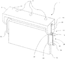
前記デフレクタ装置1は、図3に示すように、デフレクタ板19を車両前後方向に揺動可能に軸支するための車体取付ブラケット3を備えており、該車体取付ブラケット3は、車体下面Cに固定するための車体取付部14が形成された取付面11と、該取付面11の車幅方向の両端に、デフレクタ板19を揺動可能に軸支するために車体下方に延在した支持面20が設けられており、デフレクタ装置1は前記車体取付部14を介して車体下面Cに固定されている。   As shown in FIG. 3, the deflector device 1 includes a vehicle body mounting bracket 3 for pivotally supporting a deflector plate 19 so as to be swingable in the vehicle front-rear direction. A mounting surface 11 on which a vehicle body mounting portion 14 for fixing is formed, and a support surface extending below the vehicle body to pivotally support the deflector plate 19 at both ends of the mounting surface 11 in the vehicle width direction. 20 is provided, and the deflector device 1 is fixed to the lower surface C of the vehicle body via the vehicle body mounting portion 14.

前記デフレクタ板19を前記車体取付ブラケット3に車両前後方向に揺動可能に軸支する軸支手段26は、車体取付ブラケット3に対して揺動可能に軸支されたデフレクタ板支持用ブラケット23で構成されており、デフレクタ板19は、該デフレクタ板支持用ブラケット23に両側が固定されて配設されている。   A shaft support means 26 that pivotally supports the deflector plate 19 on the vehicle body mounting bracket 3 so as to be swingable in the vehicle front-rear direction is a deflector plate support bracket 23 pivotally supported on the vehicle body mounting bracket 3. The deflector plate 19 is configured such that both sides thereof are fixed to the deflector plate support bracket 23.

前記デフレクタ板支持用ブラケット23は、前記デフレクタ装置1の外側に向けて突出したブラケット掛止用突出部15を有し、該ブラケット掛止用突出部15が支持面20に形成された挿入孔12に挿入されることによって、支持面20に対して車両前後方向に揺動可能に軸支されている。よって、デフレクタ板支持用ブラケット23に固定されているデフレクタ板19も、デフレクタ板支持用ブラケット23と共に車両前後方向に揺動するようになっている。 The deflector plate support bracket 23 has a bracket latching projection 15 projecting toward the outside of the deflector device 1, and the bracket latching projection 15 is formed in the support surface 20. By being inserted into the support shaft 20, the support surface 20 is pivotally supported so as to be swingable in the vehicle front-rear direction. Therefore, the deflector plate 19 fixed to the deflector plate support bracket 23 also swings in the vehicle front-rear direction together with the deflector plate support bracket 23.

さらに前記デフレクタ装置1は、デフレクタ板19を鉛直下向きに付勢する付勢手段17を備えており、該付勢手段17は、車両上下方向に直線的に形成された弾性体18と、該弾性体18の一端を固定するよう支持面20から外側に突出して形成された付勢手段掛止部16と、他端を固定するようデフレクタ板支持用ブラケット23の下方に外側に突出して形成された付勢手段掛止部33で構成されており、弾性体18が略中間位置で前記ブラケット掛止用突出部15に巻きつけられることによって、デフレクタ板19の揺動に伴って自身が持つ弾性力が作用してデフレクタ板19を元の略鉛直下方向に付勢するよう構成されている。 The deflector device 1 further includes a biasing means 17 that biases the deflector plate 19 vertically downward. The biasing means 17 includes an elastic body 18 linearly formed in the vehicle vertical direction, and the elastic body 18. The biasing means hooking portion 16 is formed to protrude outward from the support surface 20 so as to fix one end of the body 18, and is formed to protrude outward below the deflector plate support bracket 23 so as to fix the other end. The urging means latching portion 33 is formed, and the elastic body 18 is wound around the bracket latching projection 15 at a substantially intermediate position, so that the elastic force possessed by the deflection plate 19 swings. Acts to urge the deflector plate 19 in the substantially vertical downward direction.

この第1の実施形態によれば、デフレクタ板19が車両前後方向に揺動可能なよう軸支手段が設けられ、このデフレクタ板19を鉛直下向きに付勢する付勢手段17が設けられているので、通常走行時においては付勢手段17によってデフレクタ板19が鉛直下向きに付勢された状態を維持して車両前方からホイールハウス5へ流入しようとする走行風を効果的に規制することができる。 According to the first embodiment, the pivot support means is provided so that the deflector plate 19 can swing in the vehicle front-rear direction, and the biasing means 17 for biasing the deflector plate 19 vertically downward is provided. Therefore, during normal travel, it is possible to effectively regulate the traveling wind that flows into the wheel house 5 from the front of the vehicle while maintaining the state in which the deflector plate 19 is urged vertically downward by the urging means 17. .

そして、路面上に縁石等の障害物などがあって前記デフレクタ板19が回避を必要とする場合においては、図4に示すように、デフレクタ板19がブラケット掛止用突出部15を中心にデフレクタ板支持用ブラケット23と共に揺動して障害物による破損を回避し、デフレクタ板19が最大変位した場合においてもタイヤBと干渉しないよう配設されているので、路面上に存在する縁石等の障害物との接触による破損やタイヤBとの接触による破損を防ぎつつ、デフレクタ板19の上下丈を延ばしてホイールハウス5へ流入しようとする走行風を効果的に規制することができる。 When there is an obstacle such as a curb on the road surface and the deflector plate 19 needs to be avoided, the deflector plate 19 is centered on the bracket latching protrusion 15 as shown in FIG. Since it is arranged so as not to interfere with the tire B even when the deflector plate 19 is displaced to the maximum by swinging together with the plate support bracket 23 to avoid damage due to obstacles, obstacles such as curbs present on the road surface While preventing damage due to contact with objects and damage due to contact with the tire B, it is possible to effectively regulate the traveling wind that tends to flow into the wheel house 5 by extending the vertical height of the deflector plate 19.

(第2の実施形態)
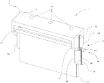
図5は、本発明の異なる実施形態(以下、第2の実施形態という)を示す斜視図であり、第2の実施形態は、デフレクタ板19を車体取付ブラケット3に直接軸支することで比較的簡単な構造でデフレクタ板19を車両前後方向に揺動可能に軸支した構成である。なお、図5において、第1の実施形態と同様の構成要素については、同一符号を付して、その詳しい説明を省略する。
(Second Embodiment)
FIG. 5 is a perspective view showing a different embodiment (hereinafter referred to as a second embodiment) of the present invention. The second embodiment is compared by directly supporting the deflector plate 19 on the vehicle body mounting bracket 3. In this configuration, the deflector plate 19 is pivotally supported so as to be swingable in the vehicle front-rear direction. In FIG. 5, the same components as those in the first embodiment are denoted by the same reference numerals, and detailed description thereof is omitted.

第2の実施形態におけるデフレクタ装置1は、図5に示すように、デフレクタ板19を車両前後方向に揺動可能に軸支する軸支手段26が、デフレクタ板19の上方に車幅方向に貫通して形成された挿入孔21と、前記支持面20に形成された前記挿入孔12と、該挿入孔21と前記挿入孔12に挿入される支持部材27によって構成されており、デフレクタ板19は、該支持部材27を中心に車両前後方向に揺動可能に軸支されている。   As shown in FIG. 5, in the deflector device 1 in the second embodiment, the shaft support means 26 that pivotally supports the deflector plate 19 so as to be swingable in the vehicle front-rear direction penetrates the deflector plate 19 in the vehicle width direction. The insertion hole 21 formed in this way, the insertion hole 12 formed in the support surface 20, and the support member 27 inserted into the insertion hole 21 and the insertion hole 12. The support member 27 is pivotally supported so as to be swingable in the vehicle front-rear direction.

付勢手段17は、前記支持部材27に巻きつけられた弾性体18によって構成されており、一端がデフレクタ板19に固定される(図示せず)と共に、他端が支持面20の裏側に固定(図示せず)されることによって、デフレクタ板19の揺動に伴って自身が持つ弾性力が作用してデフレクタ板19を元の略鉛直下方向に付勢するよう構成されている。   The biasing means 17 is composed of an elastic body 18 wound around the support member 27, and one end is fixed to the deflector plate 19 (not shown) and the other end is fixed to the back side of the support surface 20. (Not shown), it is configured such that the elastic force of the deflector plate 19 is actuated with the swing of the deflector plate 19 to urge the deflector plate 19 in the substantially vertical downward direction.

また、前記デフレクタ板19の側方上部は、前記付勢手段17を前記支持部材27に巻きつけるために左右が陥没して形成されている。 In addition, the lateral upper portion of the deflector plate 19 is formed with the left and right sides recessed to wind the biasing means 17 around the support member 27.

この第2の実施形態によれば、支持面20に形成された挿入孔12と、デフレクタ板19の上方に車幅方向に貫通して形成された挿入孔21とを貫通する支持部材27によってデフレクタ板19が車両前後方向に軸支され、さらにデフレクタ板19を鉛直下向きに付勢する付勢手段17が設けられているので、通常走行時においては付勢手段17によってデフレクタ板19が鉛直下向きに付勢された状態を維持して車両前方からホイールハウス5へ流入しようとする走行風を規制することができる。   According to the second embodiment, the deflector is provided by the support member 27 penetrating the insertion hole 12 formed in the support surface 20 and the insertion hole 21 formed through the deflector plate 19 in the vehicle width direction. Since the plate 19 is pivotally supported in the longitudinal direction of the vehicle, and further provided with urging means 17 for urging the deflector plate 19 vertically downward, the deflector plate 19 is moved vertically downward by the urging means 17 during normal traveling. It is possible to regulate the traveling wind that is in the urged state and flows into the wheel house 5 from the front of the vehicle.

そして、車両走行中に路面上に縁石等の障害物がある場合は、デフレクタ板19は、支持部材27を中心に揺動して路面上に存在する縁石等の障害物との接触による破損を回避し、さらにデフレクタ板19が最大変位した場合においてもタイヤBと干渉しないよう配設されているので、比較的簡単な構造で路面上に存在する縁石等の障害物との接触のよる破損やタイヤBとの接触による破損を防ぎつつ、デフレクタ板19の上下丈を延ばしてホイールハウス5へ流入しようとする走行風を効果的に規制することができる。 When there is an obstacle such as a curb on the road surface while the vehicle is running, the deflector plate 19 swings around the support member 27 and is damaged by contact with an obstacle such as a curb existing on the road surface. In addition, even when the deflector plate 19 is maximally displaced, it is arranged so as not to interfere with the tire B. Therefore, damage due to contact with an obstacle such as a curb existing on the road surface with a relatively simple structure. While preventing damage due to contact with the tire B, it is possible to effectively regulate the traveling wind that tends to flow into the wheel house 5 by extending the vertical length of the deflector plate 19.

(第3の実施形態)
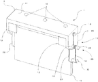
図6及び7は、本発明の異なる実施形態(以下、第3の実施形態という)を示す図であり、第3の実施形態は、デフレクタ板19を、略鉛直下方向を指向して固定された上部デフレクタ板29と、上部デフレクタ板29の下部に車両前後方向に揺動可能に軸支された下部デフレクタ板30とで構成し、下部デフレクタ板30の揺動量を減少させてデフレクタ装置1をタイヤBに近づけることを可能にした構成である。なお、図6及び7において、第1の実施形態と同様の構成要素については、同一符号を付して、その詳しい説明を省略する。
(Third embodiment)
6 and 7 are views showing different embodiments of the present invention (hereinafter referred to as a third embodiment). In the third embodiment, the deflector plate 19 is fixed so as to be directed substantially vertically downward. The upper deflector plate 29 and the lower deflector plate 30 pivotally supported on the lower portion of the upper deflector plate 29 so as to be swingable in the vehicle front-rear direction. The swing amount of the lower deflector plate 30 is reduced to reduce the deflector device 1. The configuration enables the tire B to be brought close to. 6 and 7, the same components as those in the first embodiment are denoted by the same reference numerals, and detailed description thereof is omitted.

第3の実施形態におけるデフレクタ装置1は、図6に示すように、デフレクタ板19が、上部デフレクタ板29と下部デフレクタ板30の上下で2分割されて構成されており、上部デフレクタ板29は、車体取付ブラケット3に略鉛直下向きを指向した状態で固定されると共に、下部デフレクタ板30は上部デフレクタ板29の下部に車両前後方向に揺動可能に軸支されている。   As shown in FIG. 6, the deflector device 1 according to the third embodiment is configured such that the deflector plate 19 is divided into upper and lower parts of an upper deflector plate 29 and a lower deflector plate 30, and the upper deflector plate 29 is The lower deflector plate 30 is fixed to the vehicle body mounting bracket 3 in a state of being directed substantially vertically downward, and is pivotally supported by the lower portion of the upper deflector plate 29 so as to be swingable in the vehicle front-rear direction.

前記下部デフレクタ板30を車両前後方向に揺動可能に軸支する軸支手段26は、上部デフレクタ板29の下部に車幅方向に貫通して形成された挿入孔28と、該挿入孔28に挿入された支持部材27と、該支持部材27に軸支可能なよう挿入孔32が形成されると共に下部デフレクタ板30を固定支持する下部デフレクタ板支持ブラケット31により構成されており、下部デフレクタ板30は、該下部デフレクタ板支持ブラケット31と共に支持部材27を中心として車両前後方向に揺動するよう構成されている。   A shaft support means 26 that pivotally supports the lower deflector plate 30 so as to be swingable in the vehicle front-rear direction includes an insertion hole 28 formed in the lower portion of the upper deflector plate 29 in the vehicle width direction, and an insertion hole 28. The support member 27 is inserted, and an insertion hole 32 is formed so as to be pivotally supported by the support member 27. The lower deflector plate support bracket 31 fixes and supports the lower deflector plate 30. Is configured to swing in the vehicle front-rear direction around the support member 27 together with the lower deflector plate support bracket 31.

付勢手段17は、車両上下方向に直線的に形成された弾性体18と、該弾性体18の一端を固定するよう支持面20から外側に突出して形成された付勢手段掛止部16と、他端を固定するよう下部デフレクタ板30の下方に車幅方向外方に向けて突出して形成された付勢手段掛止部35で構成されており、弾性体18が略中間位置で前記支持部材27に巻きつけられることによって、下部デフレクタ板30の揺動に伴って自身が持つ弾性力が作用して下部デフレクタ板30を元の略鉛直下方向に付勢するよう構成されている。   The urging means 17 includes an elastic body 18 linearly formed in the vehicle vertical direction, and an urging means hooking portion 16 formed to protrude outward from the support surface 20 so as to fix one end of the elastic body 18. And an urging means hooking portion 35 formed to project outward in the vehicle width direction below the lower deflector plate 30 so as to fix the other end, and the elastic body 18 is supported at the substantially intermediate position. By being wound around the member 27, the elastic force of the lower deflector plate 30 is actuated by the swinging of the lower deflector plate 30 to urge the lower deflector plate 30 in the substantially vertical downward direction.

したがって、通常走行時においては、図7(a)に示すように、前記下部デフレクタ板30は、付勢手段17によって付勢されているので鉛直下向きを指向した状態で走行し、車両前方からホイールハウス5へ流入しようとする走行風を効果的に規制する。 Accordingly, during normal traveling, as shown in FIG. 7A, the lower deflector plate 30 is urged by the urging means 17 and therefore travels in a state of being directed downward in the vertical direction. It effectively regulates the traveling wind that tends to flow into the house 5.

そして、路面上に縁石等の障害物などがあって前記下部デフレクタ板30が障害物の回避を必要とする場合は、下部デフレクタ板30は、図7(b)に示すように、支持部材27を中心として下部デフレクタ板支持ブラケット31と共に車両前後方向に揺動する構成となっており、障害物を回避して通常走行に戻れば、付勢手段17によって下部デフレクタ板30は鉛直下向きを指向した状態で走行してホイールハウス5へ流入しようとする走行風を規制する。     When there is an obstacle such as a curb on the road surface and the lower deflector plate 30 needs to avoid the obstacle, the lower deflector plate 30 is provided with a support member 27 as shown in FIG. The lower deflector plate 30 is directed vertically downward by the urging means 17 if the vehicle is swung in the vehicle longitudinal direction together with the lower deflector plate support bracket 31 around the center and avoiding obstacles and returning to normal travel. The traveling wind that travels in the state and tries to flow into the wheel house 5 is regulated.

この第3の実施形態によれば、前記デフレクタ板19が、略鉛直下向きを指向した状態で固定された上部デフレクタ29と、車両前後方向に揺動する下部デフレクタ板30とで構成され、該下部デフレクタ板30を車両前後方向に揺動可能に軸支する軸支手段と、前記下部デフレクタ板30を鉛直下向きに付勢する付勢手段17を備えているので、他の実施形態と比較してもデフレクタ板の揺動中心が路面に近づいて揺動量が減少し、その分デフレクタ装置1をホイールハウス5に近づけてデフレクタ装置1の隠蔽性を高め見栄えを向上させることができると共に、路面上存在する縁石等の障害物との接触のよる破損やタイヤBとの接触による破損を防ぎつつ、デフレクタ板19の上下丈を延ばしてホイールハウス5へ流入しようとする走行風を効果的に規制することができる。 According to the third embodiment, the deflector plate 19 includes an upper deflector 29 fixed in a state of being directed substantially vertically downward, and a lower deflector plate 30 that swings in the vehicle front-rear direction. Since the shaft support means for supporting the deflector plate 30 so as to be swingable in the longitudinal direction of the vehicle and the biasing means 17 for biasing the lower deflector plate 30 vertically downward are provided, compared with other embodiments. However, the swing center of the deflector plate approaches the road surface and the swing amount decreases, and accordingly, the deflector device 1 can be brought closer to the wheel house 5 to improve the concealment of the deflector device 1 and improve the appearance, and to be present on the road surface. While trying to flow into the wheel house 5 by extending the height of the deflector plate 19 while preventing damage due to contact with obstacles such as curbs and damage due to contact with the tire B It is possible to effectively regulate.

(第4の実施形態)
図8及び9は、本発明の異なる実施形態(以下、第4の実施形態という)を示す図であり、第4の実施形態は、デフレクタ板19の揺動量を積極的に規制してタイヤBとの接触を確実に回避可能なようデフレクタ板とタイヤBとの間に所定距離を確保することを可能にした構成である。なお、図8及び9において、第1の実施形態と同様の構成要素については、同一符号を付して、その詳しい説明を省略する。
(Fourth embodiment)
8 and 9 are views showing different embodiments of the present invention (hereinafter referred to as a fourth embodiment). In the fourth embodiment, the amount of swinging of the deflector plate 19 is positively regulated and the tire B is shown. The predetermined distance between the deflector plate and the tire B can be ensured so that contact with the tire can be reliably avoided. 8 and 9, the same components as those in the first embodiment are denoted by the same reference numerals, and detailed description thereof is omitted.

第4の実施形態におけるデフレクタ装置1は、図8に示すように、デフレクタ板19の揺動量を制限する揺動規制部材13がデフレクタ板19の前後にデフレクタ板19と所定の距離だけ離れた位置に設けられている。     In the deflector device 1 according to the fourth embodiment, as shown in FIG. 8, a position where the swing regulating member 13 that limits the swing amount of the deflector plate 19 is separated from the deflector plate 19 by a predetermined distance before and after the deflector plate 19. Is provided.

したがって、前記デフレクタ板19は、図9(a)に示すように、通常走行時においては付勢手段17によって鉛直下向きに付勢されているのでデフレクタ板19が車両前方からホイールハウス5へ流入しようとする走行風を効果的に規制する。     Accordingly, as shown in FIG. 9A, the deflector plate 19 is urged vertically downward by the urging means 17 during normal travel, so that the deflector plate 19 flows into the wheel house 5 from the front of the vehicle. It effectively regulates the driving wind.

そして、路面上に縁石等の障害物などがあって前記デフレクタ板19が回避を必要とする場合においては、図9(b)に示すように、デフレクタ板19がブラケット掛止用突出部15を中心としてデフレクタ板支持用ブラケット23と共に車両前後方向に揺動し、所定の距離だけ揺動すると揺動規制部材13が、デフレクタ板支持用ブラケット23と接触し、デフレクタ板19の揺動を規制する構成となっている。 When there is an obstacle such as a curb on the road surface and the deflector plate 19 needs to be avoided, as shown in FIG. When it swings in the longitudinal direction of the vehicle together with the deflector plate support bracket 23 as the center and swings by a predetermined distance, the swing restricting member 13 comes into contact with the deflector plate support bracket 23 and restricts the swing of the deflector plate 19. It has a configuration.

この第4の実施形態によれば、デフレクタ板19を車両前後方向に揺動可能に軸支する軸支手段26と、該デフレクタ板19を鉛直下向きに付勢する付勢手段17とを備え、さらにデフレクタ板19の揺動軌跡を規制する揺動規制部材13とを備えているので、路面上に存在する縁石等の障害物との接触のよる破損やタイヤBとの接触による破損を防ぎつつ、デフレクタ板19の上下丈を延ばしてホイールハウス5へ流入しようとする走行風を効果的に規制しながら、揺動規制部材13によってデフレクタ板19の揺動量を規制して確実にタイヤBと接触しないようデフレクタ板19とタイヤBとの間に所定距離を設けることができる。 According to the fourth embodiment, the shaft support means 26 that pivotally supports the deflector plate 19 so as to be swingable in the vehicle front-rear direction and the biasing means 17 that biases the deflector plate 19 vertically downward are provided. Further, since the swing restricting member 13 for restricting the swing trajectory of the deflector plate 19 is provided, damage due to contact with obstacles such as curbs on the road surface and damage due to contact with the tire B are prevented. In addition, the swinging amount of the deflector plate 19 is regulated by the swing regulating member 13 and the tire B is reliably contacted while effectively regulating the traveling wind that is to flow into the wheel house 5 by extending the vertical height of the deflector plate 19. It is possible to provide a predetermined distance between the deflector plate 19 and the tire B so as not to occur.

また、前記揺動規制部材13は、デフレクタ板19の揺動軌跡を規制することができればいいので、図8のようにブラケット3の両端にわたって延在してなくてもよく、図10に示すように左右両端に配設されてもよい。     Further, the swing restricting member 13 only needs to be able to restrict the swing trajectory of the deflector plate 19, and therefore does not have to extend over both ends of the bracket 3 as shown in FIG. 8, as shown in FIG. It may be disposed at both left and right ends.

(第5の実施形態)
図11及び12は、本発明の異なる実施形態(以下、第5の実施形態という)を示す図であり、第5の実施形態は、付勢手段にデフレクタ板19の揺動量を規制する規制機能を付与することによって比較的簡単な構造でデフレクタ板19の付勢と揺動量の規制を可能にした構成である。なお、図11及び12において、第1の実施形態と同様の構成要素については、同一符号を付して、その詳しい説明を省略する。
(Fifth embodiment)
FIGS. 11 and 12 are diagrams showing different embodiments of the present invention (hereinafter referred to as fifth embodiment). The fifth embodiment is a restriction function for restricting the swinging amount of the deflector plate 19 to the biasing means. By providing the above, the biasing of the deflector plate 19 and the swing amount can be regulated with a relatively simple structure. 11 and 12, the same components as those in the first embodiment are denoted by the same reference numerals, and detailed description thereof is omitted.

第5の実施形態におけるデフレクタ装置1は、図11に示すように、デフレクタ板19の揺動を規制する機能を持った付勢手段36が上記デフレクタ板19の少なくとも車両後方に設けられている。 As shown in FIG. 11, the deflector device 1 according to the fifth embodiment is provided with urging means 36 having a function of regulating the swing of the deflector plate 19 at least behind the deflector plate 19.

付勢手段36は、所定の弾性力を持った弾性体で形成されると共に、車体取付ブラケット3に少なくとも前記デフレクタ板19より車両の後方に取り付けられている。該付勢手段36とデフレクタ板19の間には、デフレクタ板の揺動量を調整可能なよう所定の間隔が設けられている。   The urging means 36 is formed of an elastic body having a predetermined elastic force, and is attached to the vehicle body mounting bracket 3 at least behind the vehicle from the deflector plate 19. A predetermined interval is provided between the biasing means 36 and the deflector plate 19 so that the swing amount of the deflector plate can be adjusted.

したがって、通常走行時は、図9(a)に示すように、前記デフレクタ板19が、付勢手段36に当接して略鉛直下向きを指向した状態を維持して車両前方からホイールハウス5へ流入しようとする走行風を規制するよう構成されている。   Therefore, during normal travel, as shown in FIG. 9A, the deflector plate 19 is in contact with the urging means 36 and maintains a state of being directed substantially vertically downward, and flows into the wheel house 5 from the front of the vehicle. It is comprised so that the driving | running | working wind to try may be controlled.

そして、路面上に縁石等の障害物などがあって前記デフレクタ板19が障害物の回避を必要とする場合においては、図12(b)に示すように、デフレクタ板19がブラケット掛止用突出部15を中心に揺動して路面上に存在する縁石等の障害物による破損を回避すると共に、自身の揺動に伴って付勢手段36と接触し、付勢手段36は、デフレクタ板19の接触によってデフレクタ板19と共に所定量は変位するものの、所定の弾性力を有しているので、その弾性力によってデフレクタ板19の所定以上の揺動を規制し、デフレクタ板19が障害物を回避したあとは付勢手段36が持つ弾性力によってデフレクタ板19を略鉛直下向きに付勢するよう構成されている。 When there is an obstacle such as a curb on the road surface and the deflector plate 19 needs to avoid the obstacle, as shown in FIG. 12 (b), the deflector plate 19 is protruded for bracket latching. It swings around the section 15 to avoid damage due to obstacles such as curbs present on the road surface, and comes into contact with the biasing means 36 along with its swinging, and the biasing means 36 is connected to the deflector plate 19. Although a predetermined amount is displaced together with the deflector plate 19 due to the contact, the elastic plate has a predetermined elastic force, and the elastic plate restricts the deflection plate 19 from swinging more than a predetermined amount so that the deflector plate 19 avoids an obstacle. After that, the deflector plate 19 is biased substantially vertically downward by the elastic force of the biasing means 36.

この第5の実施形態によれば、付勢手段36がデフレクタ板19を鉛直下向きに付勢する付勢機能とデフレクタ板19の揺動量を規制する規制機能を有するので、路面上の路面上に存在する縁石等の障害物との接触による破損を防ぎつつ、デフレクタ板19の上下丈を延ばしてホイールハウス5へ流入しようとする走行風を効果的に規制し、さらに部品点数を減らしつつもデフレクタ板19の揺動量を制限してタイヤBとの接触による破損を効果的に防止することを可能にしている。     According to the fifth embodiment, the urging means 36 has an urging function for urging the deflector plate 19 vertically downward and a regulation function for restricting the swinging amount of the deflector plate 19, so that it is on the road surface on the road surface. While preventing breakage due to contact with obstacles such as curbs, the deflector plate 19 is extended to increase the vertical length, effectively restricting the wind that flows into the wheel house 5 and further reducing the number of parts The amount of rocking of the plate 19 is limited to effectively prevent breakage due to contact with the tire B.

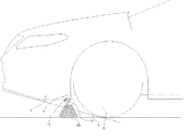
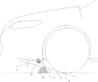
次に、本発明の第2実施例について図面を参照しながら説明する。図13及び14は実施例2における車体のデフレクタ装置を搭載した車両を横から見たときの車両全体図である。なお、実施例1と共通する部分は図2〜12と同じ符号を付して詳細な説明は省略する。 Next, a second embodiment of the present invention will be described with reference to the drawings. FIGS. 13 and 14 are overall vehicle views of a vehicle equipped with a vehicle body deflector device according to the second embodiment when viewed from the side. In addition, the part which is common in Example 1 attaches | subjects the same code | symbol as FIGS. 2-12, and abbreviate | omits detailed description.

実施例2のデフレクタ装置1は、図13に示すように、デフレクタ板19の下端部が前側タイヤBと路面とが接触する接地点と車両前部に設けられたフロントバンパーHの下端部とを結んだ線Dよりも下方に位置するよう配設されており、この線Dと路面とが交差して形成される角度Gは一般的にアプローチアングルと呼ばれ、悪路等に設けられた障害物や急勾配な坂道等でフロントバンパー下端部や車体下面Cがぶつかるか否かの判断をするときの目安になる角度であり、アプローチアングルGよりも坂道の勾配が大きい場合は、車両のフロントバンパーHの下端が坂道と接触する恐れがあることを意味している。     In the deflector device 1 according to the second embodiment, as shown in FIG. 13, the lower end portion of the deflector plate 19 connects the ground point where the front tire B and the road surface are in contact with the lower end portion of the front bumper H provided at the front portion of the vehicle. The angle G formed by intersecting the line D and the road surface is generally called an approach angle, and is an obstacle provided on a rough road or the like. This is an angle used to determine whether the front bumper lower end and the lower surface C of the vehicle body collide with each other on steep slopes, etc. If the slope of the slope is larger than the approach angle G, the front bumper H of the vehicle It means that the lower end may come into contact with the slope.

したがって、実施例2のデフレクタ装置1は、前記デフレクタ板19の上下丈を坂道と接触する領域に進入するまで路面に近づけると共に、路面上に障害物がある場合や急勾配な坂道を走行する場合においてはブラケット掛止用突出部15を中心としてデフレクタ板19が車両前後方向に揺動する構成となっている。     Therefore, the deflector device 1 according to the second embodiment brings the vertical height of the deflector plate 19 close to the road surface until entering the region in contact with the slope, and when there is an obstacle on the road surface or when traveling on a steep slope. The deflector plate 19 swings in the vehicle front-rear direction around the bracket latching protrusion 15.

この構成によれば、デフレクタ板19が障害と接触した場合にはデフレクタ板19が揺動して路面上に存在する縁石等の障害物との接触による破損を回避し、坂道走行の場合には路面と接触した場合でもデフレクタ板19が揺動して破損を回避するので、実施例1と比較しても、よりデフレクタ板19の上下丈を長くすることができ、ホイールハウス5へ流入しようとする走行風をさらに効果的に規制することができる。 According to this configuration, when the deflector plate 19 comes into contact with an obstacle, the deflector plate 19 swings to avoid damage caused by contact with an obstacle such as a curb on the road surface. Even when it contacts the road surface, the deflector plate 19 swings and avoids breakage, so that the upper and lower lengths of the deflector plate 19 can be made longer than in the first embodiment, and the inflow to the wheel house 5 is attempted. It is possible to more effectively regulate the running wind.

また、実施例2においても上記実施例1で述べた各実施形態を適用することが可能である。   In the second embodiment, each embodiment described in the first embodiment can be applied.

なお、デフレクタ装置1を車体へ取り付ける際は、ホイールハウス5の前方に位置するよう配設されればよく、車体下面の取付箇所にデフレクタ装置1を支持可能な強度があれば、車体取付ブラケット3はペリメーフレームや車体下面Cのアンダーカバー等、どのような部材に固定してもよい。 In addition, when attaching the deflector apparatus 1 to a vehicle body, it should just be arrange | positioned so that it may be located in front of the wheel house 5, and if the intensity | strength which can support the deflector apparatus 1 has the intensity | strength which can support the deflector apparatus 1, the vehicle body attachment bracket 3 May be fixed to any member such as a perimeter frame or an under cover on the lower surface C of the vehicle body.

この発明の構成と上述の実施例との対応において、この発明の軸支手段は、実施例のデフレクタ板支持用ブラケットとブラケット掛止用突出部15と挿入孔と支持部材に対応し、以下同様に、付勢手段は、実施例の弾性体と付勢手段掛止部に対応するも、この発明は、上述の実施例の構成のみに限定されるものでなく、多くの実施の形態を得ることができる。 In the correspondence between the configuration of the present invention and the above-described embodiment, the shaft support means of the present invention corresponds to the deflector plate support bracket, the bracket latching protrusion 15, the insertion hole, and the support member of the embodiment, and so on. In addition, the urging means corresponds to the elastic body and the urging means latching portion of the embodiment, but the present invention is not limited to the configuration of the above-described embodiment, and many embodiments are obtained. be able to.

本願発明の実施例1に係るデフレクタ装置を備えた車両の側面図である。It is a side view of the vehicle provided with the deflector apparatus based on Example 1 of this invention. デフレクタ装置を備えた車両を下面図である。It is a bottom view of a vehicle provided with a deflector device. 本願発明のデフレクタ装置の斜視図である。It is a perspective view of the deflector device of the present invention. 図1におけるデフレクタ装置の作動図である。It is an action | operation figure of the deflector apparatus in FIG. 本願発明の異なる実施形態の概略構成を示す図である。It is a figure which shows schematic structure of different embodiment of this invention. 本願発明の異なる実施形態の概略構成を示す図である。It is a figure which shows schematic structure of different embodiment of this invention. 図7(a)は、図6における実施形態のデフレクタ板が通常時の側面図であり、図7(b)は図6における実施形態のデフレクタ板が揺動時の側面図である。7A is a side view when the deflector plate of the embodiment in FIG. 6 is normal, and FIG. 7B is a side view when the deflector plate of the embodiment in FIG. 6 is swung. 本願発明の異なる実施形態の概略構成を示す図である。It is a figure which shows schematic structure of different embodiment of this invention. 図9(a)は、図8における実施形態のデフレクタ板が通常時の側面図であり、図9(b)は、図8における実施形態のデフレクタ板が揺動時の側面図である。9A is a side view when the deflector plate of the embodiment in FIG. 8 is normal, and FIG. 9B is a side view when the deflector plate of the embodiment in FIG. 8 swings. 図8におけるデフレクタ装置の異なる実施形態の概略構成を示す図である。It is a figure which shows schematic structure of different embodiment of the deflector apparatus in FIG. 本願発明の異なる実施形態の概略構成を示す図である。It is a figure which shows schematic structure of different embodiment of this invention. 図12(a)は、図11における実施形態のデフレクタ板が通常時の側面図であり、図12(b)は図11における実施形態のデフレクタ板が揺動時の側面図である。12A is a side view when the deflector plate of the embodiment in FIG. 11 is normal, and FIG. 12B is a side view when the deflector plate of the embodiment in FIG. 11 is swung. 本願発明の実施例2に係るデフレクタ装置を備えた車両の側面図である。It is a side view of the vehicle provided with the deflector apparatus based on Example 2 of this invention. 図13におけるデフレクタ装置の作動図である。It is an action | operation figure of the deflector apparatus in FIG. 従来のデフレクタ装置を示す図である。It is a figure which shows the conventional deflector apparatus.

符号の説明Explanation of symbols

A 車両
C 車体下面
D タイヤの接地点からフロントバンパー下端を結ぶ線
E 従来のデフレクタ板
F 走行風
F´ 従来のデフレクタ板による走行風
H フロントバンパー
1 デフレクタ装置
3 車体取付ブラケット
5 ホイールハウス
13 揺動規制部材
14 車体取付部
15 ブラケット掛止用突出部
16 付勢手段掛止部
17 付勢手段
18 弾性部材
19 デフレクタ板
23 デフレクタ板支持用ブラケット
25 縁石等
26 軸支手段
27 支持部材
29 上部デフレクタ板
30 下部デフレクタ板
31 下部デフレクタ板支持ブラケット
33 付勢手段掛止部

A Vehicle C Lower surface of vehicle body D Line connecting tire ground contact point to lower end of front bumper E Conventional deflector plate F Traveling wind F 'Traveling wind with conventional deflector plate H Front bumper 1 Deflector device 3 Car body mounting bracket 5 Wheelhouse 13 Swing restriction member 14 Car body mounting part 15 Bracket latching protrusion 16 Biasing means latching part 17 Biasing means 18 Elastic member 19 Deflector plate 23 Deflector plate support bracket 25 Curbstone 26 Supporting means 27 Support member 29 Upper deflector plate 30 Lower part Deflector plate 31 Lower deflector plate support bracket 33 Energizing means latching portion

Claims (5)

タイヤが収納されたホイールハウスの前方に設けられ、該ホイールハウス内に車両前方からの走行風が流入するのを規制するデフレクタ板を備えた車両のデフレクタ装置において、上記デフレクタ板を車両前後方向に揺動可能に軸支する軸支手段と、該デフレクタ板を略鉛直下向きに指向するように付勢する付勢手段を備えると共に、上記デフレクタ板が車両後方向に揺動した際にその下端部が上記タイヤと干渉しないように配設されていることを特徴とする車両のデフレクタ装置。 In a vehicle deflector device provided with a deflector plate that is provided in front of a wheel house that contains tires and that restricts the flow of traveling wind from the front of the vehicle into the wheel house, the deflector plate is arranged in the vehicle front-rear direction. A pivot supporting means for pivotally supporting and a biasing means for biasing the deflector plate so that the deflector plate is directed substantially vertically downward, and a lower end portion of the deflector plate when the deflector plate swings backward in the vehicle. The vehicle deflector device is arranged so as not to interfere with the tire. 上記デフレクタ板の下端部が、車両側面視において上記タイヤと路面とが接触する接触点と車両前部に設けられたフロントバンパーの下端部とを結んだ線よりも下方に位置するように配設されていることを特徴とする上記請求項1記載の車両のデフレクタ装置。 The lower end portion of the deflector plate is disposed below a line connecting a contact point where the tire and the road surface are in contact with the lower end portion of a front bumper provided at the front of the vehicle in a side view of the vehicle. The vehicle deflector device according to claim 1, wherein the vehicle deflector device is provided. 上記デフレクタ板が、略鉛直下向きに固定して設けられた上部デフレクタ板と、該上部デフレクタ板の下端部に軸支される下部デフレクタ板とを備えたことを特徴とする上記請求項1又は2に記載の車両のデフレクタ装置。 3. The deflector plate according to claim 1, wherein the deflector plate includes an upper deflector plate that is fixed substantially vertically downward, and a lower deflector plate that is pivotally supported by a lower end portion of the upper deflector plate. A vehicle deflector device according to claim 1. 上記デフレクタ板の車両後方への揺動量を規制する揺動規制部材を備えたことを特徴とする上記請求項1乃至3記載の車両のデフレクタ装置。 4. The vehicle deflector device according to claim 1, further comprising a swing restricting member that restricts a swing amount of the deflector plate toward the rear of the vehicle. 上記付勢手段は、上記デフレクタ板の下端と上記タイヤとの干渉を防ぐように該デフレクタ板を付勢する付勢力を有する弾性部材を備えたことを特徴とする上記請求項1乃至3記載の車両のデフレクタ装置。 The said urging | biasing means was equipped with the elastic member which has the urging | biasing force which urges | biases this deflector board so that the lower end of the said deflector board and the said tire may be prevented. Vehicle deflector device.
JP2008095393A 2008-04-01 2008-04-01 Vehicle deflector device Pending JP2009248604A (en)

Priority Applications (1)

Application Number Priority Date Filing Date Title
JP2008095393A JP2009248604A (en) 2008-04-01 2008-04-01 Vehicle deflector device

Applications Claiming Priority (1)

Application Number Priority Date Filing Date Title
JP2008095393A JP2009248604A (en) 2008-04-01 2008-04-01 Vehicle deflector device

Publications (1)

Publication Number Publication Date
JP2009248604A true JP2009248604A (en) 2009-10-29

Family

ID=41309714

Family Applications (1)

Application Number Title Priority Date Filing Date
JP2008095393A Pending JP2009248604A (en) 2008-04-01 2008-04-01 Vehicle deflector device

Country Status (1)

Country Link
JP (1) JP2009248604A (en)

Cited By (2)

* Cited by examiner, † Cited by third party
Publication number Priority date Publication date Assignee Title
WO2014174620A1 (en) * 2013-04-24 2014-10-30 トヨタ自動車株式会社 Flow control device for vehicle
CN112172930A (en) * 2020-09-09 2021-01-05 浙江吉利控股集团有限公司 Front wheel wind-blocking plate and vehicle

Cited By (4)

* Cited by examiner, † Cited by third party
Publication number Priority date Publication date Assignee Title
WO2014174620A1 (en) * 2013-04-24 2014-10-30 トヨタ自動車株式会社 Flow control device for vehicle
JP5888434B2 (en) * 2013-04-24 2016-03-22 トヨタ自動車株式会社 Vehicle rectifier
EP2990310A4 (en) * 2013-04-24 2016-05-11 Toyota Motor Co Ltd Flow control device for vehicle
CN112172930A (en) * 2020-09-09 2021-01-05 浙江吉利控股集团有限公司 Front wheel wind-blocking plate and vehicle

Similar Documents

Publication Publication Date Title
JP5235220B2 (en) Vehicle air rectifier cover
US8322778B1 (en) Aerodynamic drag reduction device for a trailer
JP2008013013A (en) Tire deflector of automobile
US8091941B2 (en) Lower structure of vehicle body rear part
JP2009227159A (en) Deflector device for vehicle
JP2009248604A (en) Vehicle deflector device
JP7155880B2 (en) automobile deflector structure
JP2007253657A (en) Deflector structure of vehicle
JP2010162949A (en) Vehicle body front part structure
JP2004203157A (en) Bumper structure of automobile
JP3628269B2 (en) Mounting structure for vehicle headlamps
JP2001150962A (en) Structure for attaching radiator
JP2011131679A (en) Deflector device of vehicle
JP5084805B2 (en) Vehicle front grill bracket
JP4692153B2 (en) Wheel pressure resistance reduction device
JP4389539B2 (en) Cowl structure
JPS6216145Y2 (en)
JPH11342867A (en) Splashed water spattering prevention device for vehicle
JP3624552B2 (en) Front bumper structure of automobile
JP3628264B2 (en) Vehicle headlamp mounting device
JPH10305784A (en) Car body front structure
JP2006175888A (en) Spoiler device of vehicle
JP5569338B2 (en) Aerodynamic equipment for vehicles
JP2014076705A (en) Rectification structure for vehicle
JP2018144634A (en) Tire deflector device