JP2009247019A - Image decoding apparatus, image decoding method, image encoding apparatus and image encoding method - Google Patents
Image decoding apparatus, image decoding method, image encoding apparatus and image encoding method Download PDFInfo
- Publication number
- JP2009247019A JP2009247019A JP2009175353A JP2009175353A JP2009247019A JP 2009247019 A JP2009247019 A JP 2009247019A JP 2009175353 A JP2009175353 A JP 2009175353A JP 2009175353 A JP2009175353 A JP 2009175353A JP 2009247019 A JP2009247019 A JP 2009247019A
- Authority
- JP
- Japan
- Prior art keywords
- image
- region
- unit
- information
- encoding
- Prior art date
- Legal status (The legal status is an assumption and is not a legal conclusion. Google has not performed a legal analysis and makes no representation as to the accuracy of the status listed.)
- Pending
Links
Images


Classifications
-
- H—ELECTRICITY
- H04—ELECTRIC COMMUNICATION TECHNIQUE
- H04N—PICTORIAL COMMUNICATION, e.g. TELEVISION
- H04N19/00—Methods or arrangements for coding, decoding, compressing or decompressing digital video signals
- H04N19/10—Methods or arrangements for coding, decoding, compressing or decompressing digital video signals using adaptive coding
- H04N19/189—Methods or arrangements for coding, decoding, compressing or decompressing digital video signals using adaptive coding characterised by the adaptation method, adaptation tool or adaptation type used for the adaptive coding
- H04N19/19—Methods or arrangements for coding, decoding, compressing or decompressing digital video signals using adaptive coding characterised by the adaptation method, adaptation tool or adaptation type used for the adaptive coding using optimisation based on Lagrange multipliers
-
- H—ELECTRICITY
- H04—ELECTRIC COMMUNICATION TECHNIQUE
- H04N—PICTORIAL COMMUNICATION, e.g. TELEVISION
- H04N19/00—Methods or arrangements for coding, decoding, compressing or decompressing digital video signals
- H04N19/10—Methods or arrangements for coding, decoding, compressing or decompressing digital video signals using adaptive coding
- H04N19/102—Methods or arrangements for coding, decoding, compressing or decompressing digital video signals using adaptive coding characterised by the element, parameter or selection affected or controlled by the adaptive coding
- H04N19/119—Adaptive subdivision aspects, e.g. subdivision of a picture into rectangular or non-rectangular coding blocks
-
- H—ELECTRICITY
- H04—ELECTRIC COMMUNICATION TECHNIQUE
- H04N—PICTORIAL COMMUNICATION, e.g. TELEVISION
- H04N19/00—Methods or arrangements for coding, decoding, compressing or decompressing digital video signals
- H04N19/10—Methods or arrangements for coding, decoding, compressing or decompressing digital video signals using adaptive coding
- H04N19/102—Methods or arrangements for coding, decoding, compressing or decompressing digital video signals using adaptive coding characterised by the element, parameter or selection affected or controlled by the adaptive coding
- H04N19/124—Quantisation
-
- H—ELECTRICITY
- H04—ELECTRIC COMMUNICATION TECHNIQUE
- H04N—PICTORIAL COMMUNICATION, e.g. TELEVISION
- H04N19/00—Methods or arrangements for coding, decoding, compressing or decompressing digital video signals
- H04N19/10—Methods or arrangements for coding, decoding, compressing or decompressing digital video signals using adaptive coding
- H04N19/134—Methods or arrangements for coding, decoding, compressing or decompressing digital video signals using adaptive coding characterised by the element, parameter or criterion affecting or controlling the adaptive coding
- H04N19/136—Incoming video signal characteristics or properties
- H04N19/137—Motion inside a coding unit, e.g. average field, frame or block difference
-
- H—ELECTRICITY
- H04—ELECTRIC COMMUNICATION TECHNIQUE
- H04N—PICTORIAL COMMUNICATION, e.g. TELEVISION
- H04N19/00—Methods or arrangements for coding, decoding, compressing or decompressing digital video signals
- H04N19/10—Methods or arrangements for coding, decoding, compressing or decompressing digital video signals using adaptive coding
- H04N19/134—Methods or arrangements for coding, decoding, compressing or decompressing digital video signals using adaptive coding characterised by the element, parameter or criterion affecting or controlling the adaptive coding
- H04N19/136—Incoming video signal characteristics or properties
- H04N19/14—Coding unit complexity, e.g. amount of activity or edge presence estimation
-
- H—ELECTRICITY
- H04—ELECTRIC COMMUNICATION TECHNIQUE
- H04N—PICTORIAL COMMUNICATION, e.g. TELEVISION
- H04N19/00—Methods or arrangements for coding, decoding, compressing or decompressing digital video signals
- H04N19/10—Methods or arrangements for coding, decoding, compressing or decompressing digital video signals using adaptive coding
- H04N19/134—Methods or arrangements for coding, decoding, compressing or decompressing digital video signals using adaptive coding characterised by the element, parameter or criterion affecting or controlling the adaptive coding
- H04N19/146—Data rate or code amount at the encoder output
- H04N19/147—Data rate or code amount at the encoder output according to rate distortion criteria
-
- H—ELECTRICITY
- H04—ELECTRIC COMMUNICATION TECHNIQUE
- H04N—PICTORIAL COMMUNICATION, e.g. TELEVISION
- H04N19/00—Methods or arrangements for coding, decoding, compressing or decompressing digital video signals
- H04N19/10—Methods or arrangements for coding, decoding, compressing or decompressing digital video signals using adaptive coding
- H04N19/134—Methods or arrangements for coding, decoding, compressing or decompressing digital video signals using adaptive coding characterised by the element, parameter or criterion affecting or controlling the adaptive coding
- H04N19/146—Data rate or code amount at the encoder output
- H04N19/15—Data rate or code amount at the encoder output by monitoring actual compressed data size at the memory before deciding storage at the transmission buffer
-
- H—ELECTRICITY
- H04—ELECTRIC COMMUNICATION TECHNIQUE
- H04N—PICTORIAL COMMUNICATION, e.g. TELEVISION
- H04N19/00—Methods or arrangements for coding, decoding, compressing or decompressing digital video signals
- H04N19/10—Methods or arrangements for coding, decoding, compressing or decompressing digital video signals using adaptive coding
- H04N19/169—Methods or arrangements for coding, decoding, compressing or decompressing digital video signals using adaptive coding characterised by the coding unit, i.e. the structural portion or semantic portion of the video signal being the object or the subject of the adaptive coding
- H04N19/17—Methods or arrangements for coding, decoding, compressing or decompressing digital video signals using adaptive coding characterised by the coding unit, i.e. the structural portion or semantic portion of the video signal being the object or the subject of the adaptive coding the unit being an image region, e.g. an object
- H04N19/176—Methods or arrangements for coding, decoding, compressing or decompressing digital video signals using adaptive coding characterised by the coding unit, i.e. the structural portion or semantic portion of the video signal being the object or the subject of the adaptive coding the unit being an image region, e.g. an object the region being a block, e.g. a macroblock
-
- H—ELECTRICITY
- H04—ELECTRIC COMMUNICATION TECHNIQUE
- H04N—PICTORIAL COMMUNICATION, e.g. TELEVISION
- H04N19/00—Methods or arrangements for coding, decoding, compressing or decompressing digital video signals
- H04N19/60—Methods or arrangements for coding, decoding, compressing or decompressing digital video signals using transform coding
- H04N19/61—Methods or arrangements for coding, decoding, compressing or decompressing digital video signals using transform coding in combination with predictive coding
-
- H—ELECTRICITY
- H04—ELECTRIC COMMUNICATION TECHNIQUE
- H04N—PICTORIAL COMMUNICATION, e.g. TELEVISION
- H04N19/00—Methods or arrangements for coding, decoding, compressing or decompressing digital video signals
- H04N19/10—Methods or arrangements for coding, decoding, compressing or decompressing digital video signals using adaptive coding
- H04N19/134—Methods or arrangements for coding, decoding, compressing or decompressing digital video signals using adaptive coding characterised by the element, parameter or criterion affecting or controlling the adaptive coding
- H04N19/146—Data rate or code amount at the encoder output
-
- H—ELECTRICITY
- H04—ELECTRIC COMMUNICATION TECHNIQUE
- H04N—PICTORIAL COMMUNICATION, e.g. TELEVISION
- H04N19/00—Methods or arrangements for coding, decoding, compressing or decompressing digital video signals
- H04N19/30—Methods or arrangements for coding, decoding, compressing or decompressing digital video signals using hierarchical techniques, e.g. scalability
Abstract
Description
本発明は、画像符号化装置及び符号化された画像を復号する装置及びその方法に関する。 The present invention relates to an image encoding apparatus, an apparatus for decoding an encoded image, and a method thereof.
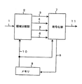
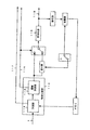
図27は、第一の従来技術である、ITU−Tの勧告H.263にもとづく動画像符号化装置の構成を示すブロック図である。同図において、1は入力デジタル画像信号(以下、単に入力画像ともいう)、101は差分器、102は予測信号、103は予測誤差信号、104は符号化部、105は符号化データ、106は復号部、107は復号された予測誤差信号、108は加算器、109は局所(ローカル)復号画像信号、110はメモリ、111は予測部、112は動きベクトルである。
FIG. 27 shows ITU-T recommendation H.264, which is the first prior art. 2 is a block diagram illustrating a configuration of a video encoding device based on H.263. FIG. In the figure, 1 is an input digital image signal (hereinafter also simply referred to as an input image), 101 is a differentiator, 102 is a prediction signal, 103 is a prediction error signal, 104 is an encoding unit, 105 is encoded data, and 106 is
符号化すべき入力画像1は、まず差分器101に入力される。差分器101は、入力画像1と予測信号102との差分をとり、それを予測誤差信号103として出力する。符号化部104は、原信号である入力画像1または予測誤差信号103を符号化して符号化データ105を出力する。符号化部104における符号化の方法として、前記勧告では、予測誤差信号103を直交変換の一種であるDCT(Discrete Cosine Transformation:離散コサイン変換)を用いて空間領域から周波数領域に変換し、得られた変換係数を線形量子化する手法が採用されている。
The
符号化データ105は二方向に分岐する。一方は受信側の画像復号装置(図示せず)に向けて送出され、他方は本装置内の復号部106に入力される。復号部106は、符号化部104と逆の動作を行い、符号化データ105から復号予測誤差信号107を生成して出力する。加算器108は、復号予測誤差信号107と予測信号102を加算し、これを復号画像信号109として出力する。予測部111は、入力画像1とメモリ110に蓄えられた1フレーム前の復号画像信号109とを用いて動き補償予測を行い、予測信号102と動きベクトル112を出力する。このとき動き補償はマクロブロックと呼ばれる16×16画素からなる固定サイズのブロック単位で行われる。動きの激しい領域内のブロックについては、オプショナルな機能として、マクロブロックを4分割した8×8画素のサブブロック単位で動き補償予測を行うこともできる。求められた動きベクトル112は画像復号装置に向かって送出され、予測信号102は差分器101および加算器108に送られる。この装置によれば、動き補償予測を用いることにより、画質を維持しながら動画像のデータ量を圧縮することができる。
The encoded
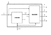
図28は第二の従来技術に係る画像符号化装置の構成図である。この装置は、L.C.Realらによる"A Very Low Bit Rate Video Coder Based on Vector Quantization"(IEEE Trans. on Image Processing, VOL.5, NO.2, Feb.1996)で提案された符号化方法にもとづく。同図において、113は領域分割部、114は予測部、115は領域決定部、116はフレーム間符号化/フレーム内符号化(インター/イントラ)情報を含む符号化モード情報、117は動きベクトル、118は符号化部、119は符号化データである。 FIG. 28 is a block diagram of an image encoding device according to the second prior art. This device is based on the encoding method proposed in "A Very Low Bit Rate Video Coder Based on Vector Quantization" (IEEE Trans. On Image Processing, VOL.5, NO.2, Feb.1996) by LCReal et al. . In the figure, 113 is a region dividing unit, 114 is a prediction unit, 115 is a region determining unit, 116 is coding mode information including interframe coding / intraframe coding (inter / intra) information, 117 is a motion vector, Reference numeral 118 denotes an encoding unit, and 119 denotes encoded data.
この装置では、まず領域分割部113で入力画像1を複数の領域に分割する。領域分割部113は、動き補償予測誤差に基づき領域の大きさを決定する。領域分割部113は、あらかじめ用意した10種類のブロックサイズ4×4,4×8,8×4,8×8,8×16,16×8,16×16,16×32,32×16,32×32の中から、フレーム間信号の分散に関して閾値を用いた判定を行い、動きの大きい領域には小さなブロックを、また、背景などの動きの小さい領域には大きなブロックを割り当てる。具体的には、予測部114で得られた予測誤差信号について領域決定部115でその分散値を計算し、これに基づきブロックサイズを決定していく。領域形状情報や符号化モード等の属性情報116、動きベクトル117もこの時点で決定され、符号化モード情報にしたがって予測誤差信号または原信号が符号化部118で符号化され、符号化データ119が得られる。以降の処理は第一の従来技術と同じである。
In this apparatus, first, the
第一の従来技術では、符号化単位の領域の形が2種類に限定される。しかも、それらはともに正方形である。したがって、画像のシーン構造または画像の特徴に適応した符号化にはおのずと限界がある。例えば、動きの大きな被写体のみについて符号量を上げたい場合、できる限りその被写体と同じ形の領域を定義したいが、この従来技術では困難である。 In the first prior art, the shape of the area of the coding unit is limited to two types. Moreover, they are both square. Therefore, there is a limit to the encoding adapted to the scene structure of the image or the characteristics of the image. For example, when it is desired to increase the amount of code only for a subject with large movement, it is difficult to define a region having the same shape as that subject as much as possible, but this conventional technique is difficult.
第二の従来技術は、複数のサイズのブロックを準備する点で第一の従来技術よりも処理の柔軟性に富む。しかし、この装置でも結局は各領域は正方形に限られる。したがって、10種類の大きさの正方形はあるとはいえ、やはり任意の形状の画像領域に対する適応性には改善の余地がある。 The second prior art is more flexible in processing than the first prior art in that it prepares blocks of a plurality of sizes. However, even in this apparatus, each area is limited to a square after all. Therefore, although there are 10 types of squares, there is still room for improvement in adaptability to an image region of an arbitrary shape.
本発明はこうした課題に鑑みてなされたものであり、その目的は、いろいろな形状に分割された領域の符号化データを正しく復号する技術を提供することにある。 The present invention has been made in view of these problems, and an object of the present invention is to provide a technique for correctly decoding encoded data in a region divided into various shapes.
本発明に係る画像復号装置は、それぞれ異なる領域形状を持ち、単位画像ブロックのセットを連結することにより形成される複数の領域の分割により符号化され、それぞれの画像毎の領域形状情報と、予測画像を生成するためのそれぞれの領域毎の情報と、予測誤差信号を復元するための前記単位画像ブロック毎の情報を含む、画像の符号化データを復号する画像復号装置において、前記符号化データを受信する入力手段と、前記受信した領域形状情報に基づいて、画像の全ての領域の形状を復元する領域形状復元手段と、受信した前記予測画像を生成するためのそれぞれの領域毎の情報と、予測誤差信号を復元するための前記単位画像ブロック毎の情報とから、領域に対応する符号化データを復号するデータ復号手段と、を備えるものである。 The image decoding device according to the present invention has different region shapes, is encoded by dividing a plurality of regions formed by connecting a set of unit image blocks, and includes region shape information and prediction for each image. In an image decoding apparatus for decoding encoded data of an image, including information for each region for generating an image and information for each unit image block for restoring a prediction error signal, the encoded data is Input means for receiving, area shape restoring means for restoring the shape of all areas of the image based on the received area shape information, information for each area for generating the received predicted image, Data decoding means for decoding encoded data corresponding to a region from information for each unit image block for restoring a prediction error signal. .
本発明に係る画像復号方法は、それぞれ異なる領域形状を持ち、単位画像ブロックのセットを連結することにより形成される複数の領域の分割により符号化され、それぞれの画像毎の領域形状情報と、予測画像を生成するためのそれぞれの領域毎の情報と、予測誤差信号を復元するための前記単位画像ブロック毎の情報を含む、画像の符号化データを復号する画像復号装置において実施され、前記符号化データを受信する入力ステップと、前記受信した領域形状情報に基づいて、画像の全ての領域の形状を復元する領域形状復元ステップと、受信した前記予測画像を生成するためのそれぞれの領域毎の情報と、予測誤差信号を復元するための前記単位画像ブロック毎の情報とから、領域に対応する符号化データを復号するデータ復号ステップと、を含むものである。 The image decoding method according to the present invention has different region shapes, is encoded by dividing a plurality of regions formed by concatenating a set of unit image blocks, and includes region shape information and prediction for each image. The encoding is performed in an image decoding apparatus that decodes encoded data of an image including information for each region for generating an image and information for each unit image block for restoring a prediction error signal. An input step for receiving data, an area shape restoration step for restoring the shape of all areas of the image based on the received area shape information, and information for each area for generating the received predicted image And a data decoding step of decoding encoded data corresponding to the region from the information for each unit image block for restoring the prediction error signal , It is intended to include.
本発明に係る画像符号化装置は、それぞれ異なる領域形状を持ち、単位画像ブロックのセットを連結することにより形成される複数の領域の分割により画像を符号化する画像符号化装置において、画像の所定単位画像ブロックへの最初の分割、及びその後の単位画像ブロックのセットの連結により、それぞれの領域の形状を形成し、画像における全ての領域の形状を形成し、画像における全ての領域の形状を特定する情報として領域形状情報を生成する領域形状生成手段と、予測画像を生成するためのそれぞれの領域毎の情報を決定し、予測誤差信号を復元するための前記単位画像ブロック毎の情報を生成する予測手段と、それぞれの画像毎の前記領域形状情報と、予測画像を生成するためのそれぞれの領域毎の情報と、予測誤差信号を復元するための前記単位画像ブロック毎の情報とを符号化する符号化手段と、を備えるものである。 An image encoding device according to the present invention is an image encoding device that encodes an image by dividing a plurality of regions each having a different region shape and formed by connecting a set of unit image blocks. By first dividing into unit image blocks and then connecting a set of unit image blocks, the shape of each region is formed, the shape of all regions in the image is formed, and the shape of all regions in the image is specified Region shape generation means for generating region shape information as information to be determined, information for each region for generating a prediction image is determined, and information for each unit image block for restoring a prediction error signal is generated Restoring the prediction means, the area shape information for each image, the information for each area for generating a predicted image, and the prediction error signal Encoding means for encoding and said unit image blocks each of information because, those comprising a.
本発明に係る画像符号化方法は、それぞれ異なる領域形状を持ち、単位画像ブロックのセットを連結することにより形成される複数の領域の分割により画像を符号化する画像符号化装置において実施され、画像の所定単位画像ブロックへの最初の分割、及びその後の単位画像ブロックのセットの連結により、それぞれの領域の形状を形成し、画像における全ての領域の形状を形成し、画像における全ての領域の形状を特定する情報として領域形状情報を生成する領域形状生成ステップと、予測画像を生成するためのそれぞれの領域毎の情報を決定し、予測誤差信号を復元するための前記単位画像ブロック毎の情報を生成する予測ステップと、それぞれの画像毎の前記領域形状情報と、予測画像を生成するためのそれぞれの領域毎の情報と、予測誤差信号を復元するための前記単位画像ブロック毎の情報とを符号化する符号化ステップと、を含むものである。 An image encoding method according to the present invention is implemented in an image encoding apparatus that encodes an image by dividing a plurality of regions each having a different region shape and formed by connecting a set of unit image blocks. The first division into a predetermined unit image block and the subsequent connection of a set of unit image blocks form the shape of each region, form the shape of all regions in the image, and shape of all regions in the image Region shape generation step for generating region shape information as information for identifying the information, and for each unit image block for restoring a prediction error signal, determining information for each region for generating a prediction image A prediction step to be generated, the region shape information for each image, information for each region for generating a predicted image, and a prediction An encoding step of encoding the said unit image blocks each of information for restoring the error signal, is intended to include.
本発明によれば、符号化装置でいろいろな形状の領域が生成されていても対応することができる。 According to the present invention, even if regions having various shapes are generated by the encoding device, it can be handled.
実施の形態1.
図1は本実施の形態に係る動画像符号化装置の構成を示すブロック図である。この装置は、例えばテレビ電話やテレビ会議等、画像通信用の携帯または据置型機器に利用できる。また、デジタルVTR、ビデオサーバーなどの画像蓄積および記録装置における動画像符号化装置として利用できる。さらに、この装置における処理の手順は、ソフトウエアまたはDSPのファームウエアの形で実装される動画像符号化プログラムとしても利用できる。
FIG. 1 is a block diagram showing a configuration of a moving picture encoding apparatus according to the present embodiment. This apparatus can be used for portable or stationary devices for image communication such as videophone and video conference. Further, it can be used as a moving image encoding device in an image storage and recording device such as a digital VTR and a video server. Furthermore, the processing procedure in this apparatus can also be used as a moving image encoding program implemented in the form of software or DSP firmware.
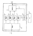
図1において、1は入力画像、2は領域分割部、3は領域形状情報、4は領域画像信号、5は領域動き情報、6は領域属性情報、7は符号化部、8は局所復号画像、9はメモリ、10は参照画像、11は符号化ビットストリームである。図2は本装置の動作を示すフローチャートである。図1、図2をもとに、まず装置全体の動作を説明する。 In FIG. 1, 1 is an input image, 2 is a region dividing unit, 3 is region shape information, 4 is a region image signal, 5 is region motion information, 6 is region attribute information, 7 is an encoding unit, and 8 is a locally decoded image. , 9 is a memory, 10 is a reference image, and 11 is an encoded bit stream. FIG. 2 is a flowchart showing the operation of this apparatus. First, the operation of the entire apparatus will be described with reference to FIGS.
入力画像1は領域分割部2に入力され(S1)、ここで複数の領域に分割される。領域分割部2は後述のごとく初期分割(S2)、近傍領域統合(S3)の2系統の処理を行う。領域分割部2は、分割の結果得られる各領域について形状情報3、画像信号4、動き情報5、各領域の符号化モードなどの属性情報6を符号化部7へ受け渡す。符号化部7では、これらの情報を所定の符号化方法に基づいてビットパターンに変換および多重化し、符号化ビットストリーム11として出力する(S4、S5)。また、動き補償予測に基づく領域分割および符号化を行うために、符号化部7では領域ごとに局所復号画像8を生成し、これをメモリ9に蓄えておく。領域分割部2および符号化部7はメモリ9に蓄えられた局所復号画像を参照画像10として取り出し、動き補償予測を行う。
The
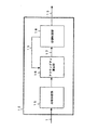
図3は領域分割部2の詳細な構成図である。同図において、12は分割処理部、13は初期分割形状情報、14は統合処理部である。
FIG. 3 is a detailed configuration diagram of the
(1)初期分割
図2のS2に相当する初期分割は分割処理部12において行う。初期分割とは、統合に進む前に行われる分割をいい、分割の合計回数は画像の状態、つまり画像の特徴または特性に依存する。
(1) Initial division The initial division corresponding to S2 in FIG. The initial division refers to division performed before proceeding to integration, and the total number of divisions depends on the state of the image, that is, the characteristics or characteristics of the image.
図4に分割処理部12の内部構成を示す。同図において、15は均等分割部、16はアクティビティ算出部、17はアクティビティ、18は分割判定部、19は分割状態指示信号である。アクティビティとは、画像の特徴または特性を判定するために、所定の性質に関して数値化されたデータである。ここではアクティビティとして、領域の動き補償予測に伴う予測誤差電力を採用する。
FIG. 4 shows an internal configuration of the
図19はブロックマッチング法による動き補償予測の方法を示している。ブロックマッチング法では、つぎの式を与えるベクトルvが被予測領域Sの動きベクトルとして求められる。

この結果得られたベクトルによって、予測画像はfs(x+vx,y+vy,t−1)で与えられ、予測誤差電力、すなわちアクティビティはDminとなる。この方法でアクティビティを定義することにより、画像の局所的な動きの複雑さに応じて領域分割を行うことができる。動きの激しい部分を密に、動きの少ない部分を粗く符号化するなどの制御が可能になる。なお、アフィン動きパラメータを求めるアフィン動き補償、3次元的な動きを検出する Perspective 動き補償などを利用してもよい。 With the vector obtained as a result, the predicted image is given by fs (x + v x , y + v y , t−1), and the prediction error power, that is, the activity is D min . By defining the activity in this way, it is possible to perform region segmentation according to the complexity of the local motion of the image. It is possible to perform control such as encoding a portion with a large amount of motion densely and a portion with a small amount of motion roughly. Note that affine motion compensation for obtaining affine motion parameters, perspective motion compensation for detecting three-dimensional motion, and the like may be used.
図5は分割処理部12の動作を示すフローチャートである。同図のごとく、まず均等分割部15で無条件に均等ブロック分割を行う(S8)。この際、例えば図6のように1フレームを32×32画素のブロックに分割する。この分割処理を第0分割ステージとよぶ。第0分割ステージで生成されたブロック数をN0、各ブロックをB0 n(1≦n≦N0)と表記する。
FIG. 5 is a flowchart showing the operation of the
つづいて、各B0 nについてさらにブロック分割を行うかどうかを個別に判定する(S9)。このため、アクティビティ算出部16において各B0 nのアクティビティ17を算出する。分割判定部18は、あらかじめ設定した閾値TH0と各ブロックのアクティビティを比較し、アクティビティ17がTH0よりも大きい場合、そのB0 nをさらに4分割する(S10)。これが第1分割ステージである。 図7は第1分割ステージ終了時点の画像の分割状態である。新たに生成された16×16画素ブロックの数をN1、各ブロックをB1 n(1≦n≦N1)と表記する。この後、各B1 nのアクティビティを算出し、閾値TH1を用いて第2分割ステージを行う。以降、第j分割ステージで生成されたブロックBj nに閾値THjを適用し、第j+1分割ステージを実行する(S13〜S16)。このjが所定の上限値に達したとき、初期分割を打ち切る。ここでは説明のために第2分割ステージで分割を打ち切るとする。この場合、最終的に図8に示すブロックが生成される。ブロックのサイズは8×8画素〜32×32画素である。初期分割終了時点でブロック数はM0とし、各ブロックを初期領域S0 nと表記する。S0 nの形状情報は初期分割形状情報13として統合処理部14に渡される。
Subsequently, it is individually determined whether or not further block division is performed for each B 0 n (S9). For this reason, the
(2)近傍領域の統合
ついで統合処理部14において、各S0 nについて近傍領域との統合を行う。統合処理部14の内部構成図を図9に示す。同図において、20はラベリング部、21は近傍領域設定部、22は暫定符号化部、23は復号部、24は符号化歪み算出部、25は評価値算出部、26は評価値算出に用いる定数、27は統合判定部、28は統合処理反復指示信号である。
(2) Integration of neighboring areas Next, the
図10は統合処理部14の動作を示すフローチャートである。同図のごとく、一定のルールに従い、まずラベリング部20で初期領域S0 nに番号、つまりラベルを付ける(S17)。例えば、画像フレームを画素単位に左上隅から右下隅に向かって水平に走査しながら領域に順に番号を与えていく。図11にラベル付けの簡単な例を示す。同図のごとく、走査線上に現れる順に、領域にラベル「1」「2」…を付していく。その際、領域の大きさは問わない。以下、領域Sk nのラベル値をl(Sk n)と表記する。なお、このkは後述の第k統合ステージに対応し、初期状態ではk=0である。
FIG. 10 is a flowchart showing the operation of the
つぎに近傍領域設定部21で各領域の「近傍領域」をラベルを利用して定義する(S18)。図12は近傍領域の例である。同図は図11のラベルに基づいて領域S0 nの近傍領域を示している。すなわち、対象となる領域Aと辺で接し、かつ対象となる領域よりもラベル値が大きい領域B,C,Dを近傍領域と定義する。 Next, the “neighboring area” of each area is defined by using the label in the neighboring area setting unit 21 (S18). FIG. 12 shows an example of the neighborhood region. This figure shows a region near the region S 0 n based on the label in FIG. In other words, regions B, C, and D that are in contact with the target region A at the sides and have a label value larger than the target region are defined as neighboring regions.
つづいて、領域とその近傍領域の統合の可否を領域ごとに判定していく。このため、暫定符号化部22、復号部23、符号化歪み算出部24、評価値算出部25で統合のための評価値を算出する(S19)。評価値は次式に示す符号量−歪みコストL(Sk n)である。
Subsequently, it is determined for each region whether or not the region and its neighboring region can be integrated. Therefore, the
L(Sk n) = D(Sk n) + λR(Sk n) (式1) L (S k n ) = D (S k n ) + λR (S k n ) (Formula 1)
ここでD(Sk n)はSk nの符号化歪み、つまり二乗誤差総和、R(Sk n)はSk nの符号量、λは定数26である。統合はL(Sk n)を小さくする方向に進める。L(Sk n)を小さくすることは、与えられた定数λのもとで、所定の符号量の範囲内で符号化歪みを小さくすることに相当する。フレーム内のL(Sk n)の総和を小さくすることにより、同一の符号量を用いたときの符号化歪みを低減することができる。 Here, D (S k n ) is the encoding distortion of S k n , that is, the sum of square errors, R (S k n ) is the code amount of S k n , and λ is a constant 26. Integration proceeds in the direction of decreasing L (S k n ). Reducing L (S k n ) corresponds to reducing the coding distortion within a predetermined code amount within a given constant λ. By reducing the sum of L (S k n ) in the frame, it is possible to reduce coding distortion when the same code amount is used.
図13はS19の詳細なフローチャートである。まず暫定符号化部22においてSk nを予備的に符号化する(S22)。この符号化の目的は、符号量R(Sk n)の算出と、符号化歪みD(Sk n)導出の準備にある。本実施の形態では、暫定符号化部22は参照画像10を用いて動き補償予測を行う。符号化されるデータは、画像データ、つまり予測誤差信号または原信号、予測画像を特定するための動き情報、符号化モードなどの属性情報を含み、これらの符号量の総和がR(Sk n)である。予測誤差信号は領域Sk nの原信号と予測画像の差として得られる。
FIG. 13 is a detailed flowchart of S19. First,
一方、復号部23では、暫定符号化部22で得られた符号化データを用いてSk nの局所復号画像を生成する(S23)。次いで、符号化歪み算出部24で局所復号画像と原画像の歪みD(Sk n)を計算する(S24)。評価値算出部25はR(Sk n)とD(Sk n)をもとに符号量−歪みコストL(Sk n)を計算する(S25)。
On the other hand, the
工程S19では以上の評価値算出をすべての領域について、
1.各領域Sk n自身…L(Sk n)
2.Sk nの近傍領域Ni[Sk n]…L(Ni[Sk n])
3.Sk nとNi[Sk n]を仮に統合した領域…L(Sk n +Ni[Sk n])
の3種類について実施する。ここでNi[Sk n]はSk nの近傍領域を示し、iは複数の近傍領域を区別する番号である。
In step S19, the above evaluation value calculation is performed for all regions.
1. Each of the regions S k n own ... L (S k n)
2. S k near the n region N i [S k n] ... L (N i [S k n])
3. A region where S k n and N i [S k n ] are temporarily integrated ... L (S k n + N i [S k n ])
It carries out about three types. Here, N i [S k n ] indicates a neighboring region of S k n , and i is a number for distinguishing a plurality of neighboring regions.
次いで統合判定部27において、画像フレーム内で、
DL=L(Sk n )+L(Ni[Sk n])−L(Sk n +Ni[Sk n])
が最大となる個所を探し、そのSk nとNi[Sk n]を統合する(S20)。これが第k統合ステージである。この後、統合判定部27はラベリング部20に対して統合処理反復指示信号28を介してラベルの更新を指示する。ラベリング部20は、ラベルl(Ni[Sk n])をラベルl(Sk n)で置き換え、近傍領域設定部21で近傍領域を再設定する。これで新しい領域Sk+1 nと近傍領域Ni[Sk+1 n]が得られ、L(Sk+1 n)、 L(Ni[Sk+1 n])、 L(Sk+1 n +Ni[Sk+1 n])が求まる。統合判定部27は、DLの値が正になる組み合わせがなくなった時点でラベリング部20への指示を停止し、統合処理を終了する(S21)。
Next, in the
D L = L (S k n ) + L (N i [S k n ]) − L (S k n + N i [S k n ])
Is searched for, and S k n and N i [S k n ] are integrated (S20). This is the k-th integration stage. Thereafter, the
以上で領域の分割と統合に関する処理が終了し、最終的に入力画像1の領域分割状態を表す情報3、各領域の画像データ4、動き情報5、属性情報6が符号化部7に出力される。この後、所定の符号化手法で符号化が行われる。
This completes the processing related to the division and integration of the regions, and finally, the
本実施の形態では、単に分割だけではなく、統合も行った。このため最終的には、各領域がいろいろな大きさの正方形ブロックの集合で表現できる。例えば画像内で動きの大きな被写体を、その輪郭線に近い形のひとつの領域に統合することができる。この結果、被写体ごとに量子化パラメータを変えて符号量を制御する等、実際の画像の構造に柔軟に対応することができる。また、与えられた符号量の制約下で符号化歪みを最小化する最適な領域分割が実現される。そのため、従来一般的な動画像符号化装置に比べて、より高い画質をより少ない符号量で実現することが容易になる。 In this embodiment, not only division but also integration is performed. For this reason, each area can finally be represented by a set of square blocks of various sizes. For example, a subject with a large movement in the image can be integrated into one region having a shape close to the contour line. As a result, it is possible to flexibly deal with the actual image structure, such as controlling the code amount by changing the quantization parameter for each subject. In addition, optimal region division that minimizes encoding distortion under a given code amount constraint is realized. For this reason, it is easy to realize higher image quality with a smaller code amount as compared with a conventional general video encoding device.
なお、本実施の形態では初期分割を第2分割ステージで打ち切ったが、これは当然別のステージで打ち切ってよい。例えば、画像全体の動きが小さい場合は第1ステージで打ち切り、逆の場合はステージ数を増やしてもよい。また、本実施の形態では、画像フレームを符号化の対象としたが、画像フレーム中の任意形状の被写体を外接四角形で囲んだ矩形画像データなどについても同様に適用が可能である。 In the present embodiment, the initial division is terminated at the second division stage, but this may naturally be terminated at another stage. For example, when the movement of the entire image is small, the first stage may be interrupted, and in the opposite case, the number of stages may be increased. In the present embodiment, the image frame is the target of encoding. However, the present invention can be similarly applied to rectangular image data in which a subject of an arbitrary shape in the image frame is surrounded by a circumscribed rectangle.
本実施の形態では、符号化部7および暫定符号化部22について、領域Sk nの符号化をDCTと線形量子化の組み合わせで行ったが、これは他の符号化方法、例えばベクトル量子化、サブバンド符号化、ウェーブレット符号化などを用いてもよい。符号化方法を複数用意し、最も符号化効率のよい方法を選択的に用いる構成にしてもよい。
In the present embodiment, encoding of the region S k n is performed by the combination of DCT and linear quantization for the
本実施の形態ではアクティビティとして予測誤差電力を採用したが、それ以外の例として以下のものが考えられる。 In the present embodiment, the prediction error power is adopted as the activity, but the following can be considered as other examples.
第一の例は領域内の分散値である。分散値は領域の画素分布の複雑さを表しており、エッジなど画素値が急激に変化する画像を含む領域では分散値が大きくなる。領域S内の画素値をfs(x,y,t)とし、領域S内の画素値の平均値をμsとすると、分散値σsは次式で与えられる。
第二の例は領域内のエッジ強度である。エッジ強度は例えば、G.Robinsonによる「Edge detection by compass gradient masks」(Journal of Computer Graphics and Image Processing, Vol.6, No.5, Oct.1977)に記載されるソーベル演算子(Sobel Operator)で求めたり、エッジ上に分布する画素数(エッジ分布面積)として求めることができる。この方法の場合、画像のエッジ構造に応じて領域を分割することができ、エッジが局在する部分を密に、エッジが存在しない部分を粗く符号化する制御も可能である。 The second example is the edge strength in the region. The edge strength is, for example, the Sobel Operator described in “Edge detection by compass gradient masks” by G. Robinson (Journal of Computer Graphics and Image Processing, Vol. 6, No. 5, Oct. 1977). Or the number of pixels distributed on the edge (edge distribution area). In the case of this method, it is possible to divide the region according to the edge structure of the image, and it is also possible to control to encode a portion where the edge is localized densely and a portion where the edge does not exist roughly.
第三の例として、領域の動き補償予測に基づく動きパラメータの大きさが挙げられる。動き補償予測の結果、動きパラメータが求められる。ブロックマッチング法の場合はベクトルvがそれである。この方法によれば、画像の動きの度合いに応じて領域を分割することができ、被写体領域など局所的に大きい動きが生じる部分を密に、背景領域など動きがあまり生じない部分を粗く符号化する制御も可能である。 As a third example, the size of a motion parameter based on motion compensation prediction of a region can be given. As a result of the motion compensation prediction, a motion parameter is obtained. In the case of the block matching method, this is the vector v. According to this method, an area can be divided according to the degree of motion of an image, and a portion where a large local motion such as a subject region is densely encoded, and a portion such as a background region where little motion occurs is roughly encoded. It is also possible to perform control.
第四の例は、領域の動き補償予測に基づく動きパラメータの符号量と、予測誤差電力の線形和である。この場合の評価値を次式で定義する。
Lmc=Dmc+λRmc (式2)
The fourth example is a linear sum of a motion parameter code amount based on motion compensation prediction of a region and prediction error power. The evaluation value in this case is defined by the following equation.
L mc = D mc + λR mc (Formula 2)
ここでDmcは動きパラメータ検出の過程で求まる予測誤差電力、λは定数、Rmcは動きパラメータの符号量である。Lmcを最小にする動きパラメータを求め、その時の評価値をアクティビティとする。この方法によれば、画像の動きの複雑さによる情報量と動きパラメータの情報量とを含めたトータルの符号化コストが小さくなるよう領域が分割され、少ない情報量で領域の符号化を行うことができる。 Here, D mc is the prediction error power obtained in the process of motion parameter detection, λ is a constant, and R mc is the code amount of the motion parameter. A motion parameter that minimizes L mc is obtained, and the evaluation value at that time is defined as an activity. According to this method, the region is divided so that the total coding cost including the information amount due to the complexity of the motion of the image and the information amount of the motion parameter is reduced, and the region is encoded with a small amount of information. Can do.
第五の例は、いままで述べたアクティビティの値の線形和である。各アクティビティ値に適度に重み付けを行うことにより、種々の画像への対応が可能となる。 The fifth example is the linear sum of the activity values described so far. By appropriately weighting each activity value, it is possible to cope with various images.
本実施の形態では、領域分割部2の中に分割処理部12を設け、ここで初期分割を行った。しかし、当然ながら、初期分割を装置の外で行うことも可能である。その場合、分割処理部12を削除し、予め複数の領域に分割された画像を入力して統合処理すればよい。
In the present embodiment, the
実施の形態2.
本実施の形態は、実施の形態1の領域分割部2を一部変形した装置に関する。図14は本実施の形態における領域分割部2の内部構成図である。同図のごとく、実施の形態2の領域分割部2は、図3の分割処理部12を均等分割部15に置き換えた形である。この構成において、図15に示すごとく、初期分割処理ではアクティビティの閾値判定を行わず、無条件に領域の最小面積の正方ブロックに均等分割する。最小の領域面積は設定可能としてもよい。
The present embodiment relates to an apparatus obtained by partially modifying the
本実施の形態では閾値の設定が不要であり、符号量−歪みコストのみを評価値として領域分割が行われる。したがって、閾値の設定に関連する手続が不要となるほか、アクティビティの算出、比較判定の処理が不要になる。このため、これらの処理に関する計算負荷の軽減を図る場合は実施の形態1にかえて本実施の形態を利用することができる。 In this embodiment, it is not necessary to set a threshold value, and region division is performed using only the code amount-distortion cost as an evaluation value. Therefore, procedures related to the threshold setting are not required, and activity calculation and comparison determination processing are not required. For this reason, this embodiment can be used in place of the first embodiment when reducing the calculation load related to these processes.
実施の形態3.
本実施の形態の分割処理では、アクティビティだけでなく、領域の重要度を示す指標(以下、クラスという)も含めて分割の可否を判断する。重要度が高い領域ほど密に符号化されることが望ましく、領域面積は小さくする。重要度が低い領域はできるだけ大きくとり、画素あたりの符号量を削減する。
In the division processing according to the present embodiment, whether or not division is possible is determined by including not only the activity but also an index (hereinafter referred to as a class) indicating the importance of the area. It is desirable that the region having higher importance is encoded more densely, and the region area is reduced. The area with low importance is set as large as possible to reduce the code amount per pixel.
アクティビティは例えば領域内で閉じた局所的な統計量である。一方、本実施の形態のクラスは領域間にまたがる画像の特徴に基づく。本実施の形態では、領域を横断する被写体構造に起因して、人がどの程度その領域を見るか、つまり人の注視度をもとにクラスを定義する。例えば、ある領域のエッジ分布が広範囲にまたがり、近傍領域との連結が強い場合は、その領域はある被写体の境界に位置する可能性が高い。 An activity is, for example, a local statistic that is closed within a region. On the other hand, the class of the present embodiment is based on the characteristics of an image that spans between regions. In the present embodiment, the class is defined based on how much a person sees the area due to the subject structure crossing the area, that is, based on the degree of gaze of the person. For example, when the edge distribution of a certain region extends over a wide range and the connection with the neighboring region is strong, the region is likely to be located at the boundary of a certain subject.
図16は本実施の形態における分割処理部12の内部構成図である。それ以外の構成は実施の形態1と同様であり、実施の形態1と異なる部分を中心に説明する。同図において、29はクラス識別部、30はクラス、31は分割判定部である。図17は図16に示す分割処理部12の動作を示すフローチャートである。
FIG. 16 is an internal configuration diagram of the
図17のごとく、まず均等分割(S26)が行われる。この後、クラス識別部29で各領域のクラス30が決定される(S27)。クラス識別部29は、領域内分散の大きさα、領域内エッジ分布の状態β(エッジの方向、分布面積などを含む)、近傍領域とのエッジの連結性γを評価してクラスを決定する。例えば、領域内分散αが所定値よりも小さい領域をもっとも低いクラス(クラスA)とし、αが大きい領域についてはさらに領域内エッジ分布βを求める。βの定量化は、例えば前述のソーベル演算子(Sobel Operator)などでできる。βが所定値より小さい場合、その領域は被写体境界よりむしろ独立したエッジをもつ小領域とみなして中程度のクラス(クラスB)とする。βがある程度大きいときは連結性γを評価し、γが大きい場合は最重要クラス(クラスC)に分類する。
As shown in FIG. 17, the equal division (S26) is first performed. Thereafter, the
クラスへの分類の後、アクティビティ算出部16においてアクティビティ17が計算され、分割判定部31でまずアクティビティに関する閾値判定が行われる(S28)。ここで分割すべきと判定された領域については、次いでクラス30に基づき、分割の許否が判定される(S29)。このため、分割判定部31は各クラスの領域をどの程度の大きさの領域まで分割してよいか、あらかじめ基準をもっている。クラスに関しても分割が許可されれば、その領域を分割する(S30)。これをすべての領域について行い、さらに分割されて新たに生じた領域も同様の分割処理を行う(S33〜S38)。
After classifying into classes, the
本実施の形態によれば、複数の領域にまたがるような画像の特徴、とくに被写体の輪郭線を考慮して画像の符号化を行うことができる。注視度の低い領域は粗く符号化して情報量を削減し、その分、注視度の高い領域に情報量を充当するような制御が可能となる。 According to the present embodiment, it is possible to encode an image in consideration of image characteristics that span a plurality of regions, in particular, a contour line of a subject. A region with a low gaze degree is roughly encoded to reduce the amount of information, and accordingly, control can be performed so that the amount of information is applied to a region with a high gaze degree.
実施の形態4.
実施の形態3ではクラス決定に人の注視度を用いた。本実施の形態では画像の特徴量を用いる。本実施の形態では、ある既知の画像の特徴量を保持しておき、それと各領域から算出した特徴量との合致度をもとにクラスを決める。
In the third embodiment, the human gaze degree is used for class determination. In this embodiment, image feature amounts are used. In the present embodiment, a feature amount of a known image is held, and a class is determined based on the degree of matching between the feature amount and a feature amount calculated from each region.
例えば、人の顔の画像については、いままでに数多くの研究がなされており、顔の構造を特徴量で数値化するさまざまな手法が提案されている。この特徴量を保持しておけば、画像の中から人の顔(これは概して重要度が高い)を検出することができる。また、その他の被写体についても、輝度やテクスチャ情報をもとに特徴量で記述できる場合も多い。人の顔を鮮明に表現したければ、人の顔の特徴量に合致する特徴量をもつ領域を最重要クラスAとし、それ以外の領域を通常の重要度のクラスBなどとする。 For example, many studies have been conducted on human face images, and various methods for quantifying the face structure with feature values have been proposed. If this feature amount is held, a human face (which is generally highly important) can be detected from the image. In addition, other subjects can often be described by feature amounts based on luminance and texture information. In order to express a person's face clearly, an area having a feature quantity that matches the feature quantity of the person's face is set as the most important class A, and other areas are set as a class B of normal importance.
図18は本実施の形態におけるクラス識別部29の構成図である。他の部分は実施の形態3同等である。図18において、32は特徴量メモリ、33は特徴合致度算出部、34はクラス決定部である。
FIG. 18 is a configuration diagram of the
特徴量メモリ32には、被写体に関する特徴量をクラスに分類して被写体ごとに保持しておく。特徴合致度算出部33は、入力画像1と、各クラスに分類された被写体の特徴量との合致度をそれぞれ算出する。合致度は例えば、入力画像1の特徴量と特徴量メモリ32中の特徴量との誤差として求める。次いで、クラス決定部34で最も合致度の高かった被写体を検出し、その被写体の属するクラスに当該領域を分類する。
In the
以上、本実施の形態によれば、画像の特徴量によって、いわば被写体の認識または検出が可能になる。そのうえで必要な被写体については画質を高めることができる。被写体のクラス分けを人の注視度に関連する特徴量をもとに行ってもよく、その場合、画像に対する人の視覚特性を考慮した符号化を行うことができる。 As described above, according to the present embodiment, it is possible to recognize or detect a subject based on the feature amount of an image. In addition, the image quality can be improved for necessary subjects. Subject classification may be performed based on a feature amount related to a person's gaze degree, and in that case, encoding in consideration of human visual characteristics with respect to an image can be performed.
実施の形態5.
実施の形態1では、統合処理の際に符号化歪みを考慮した。本実施の形態では、分割処理の段階で符号化歪みを考慮する。
In the first embodiment, encoding distortion is considered in the integration process. In the present embodiment, encoding distortion is taken into consideration at the stage of division processing.
図20は本実施の形態における分割処理部12の内部構成図である。同図において、35は分割判定部、36は分割処理反復指示信号である。図21は図20の分割処理部12の動作を表すフローチャートである。
FIG. 20 is an internal configuration diagram of the
本実施の形態の分割処理部12は、実施の形態1で導入した式1を用いる。この式の利用により、初期分割処理がフレーム内のL(Sk n)の総和を小さくする方向で行われ、同一の符号量を用いたときの符号化歪みを低減することができる。
The
図21のごとく、まず均等分割部15において、例えば図6の状態になるように均等ブロック分割を行う(S39)。これが第0分割ステージに当たる。このとき得られたブロック数をN0、各ブロックをB0 n(1≦n≦N0)と表記する。各B0 nについてさらにブロック分割を行うかどうかを判定する。B0 nに関するL(B0 n)と、 B0 nを4分割して得られる各サブブロックSB0 n(i)(1≦i≦4)に関するL(SB0 n(i))の総和が比較され、後者が小さければ分割を許可する。
As shown in FIG. 21, first, the
符号量−歪みコストの算出にあたり、まず暫定符号化部22においてB0 nおよびSB0 n(i)の符号化を行う。次いで復号部23において、暫定符号化部22で得られた符号化データからB0 nおよびSB0 n(i)の局所復号画像を生成する。つぎに符号化歪み算出部24で局所復号画像と原画像との間の歪みD(B0 n) 、D(SB0 n(i))を計算する。評価値算出部25は、符号量R(B0 n)、 R(SB0 n(i))、符号化歪みD(B0 n)、D(SB0 n(i))をもとにL(B0 n)、L(SB0 n(i))を計算する(S40、S41)。
In calculating the code amount-distortion cost, first, the
分割判定部35は、L(B0 n)と、4つのサブブロックのL(SB0 n(i))(i=1,2,3,4)の総和とを比較し(S42)、後者の方が小さければB0 nを4つのSB0 n(i)に分割する(S43)。これが第1分割ステージに当たる。SB0 n(i)として分割されたブロックを新たにB1 n(1≦n≦N1)と表記し、B1 nに対して同様の分割判定を行う(S46〜S51)。以下、同様の分割処理が所定回数行われる。最終的に例えば図8に示す分割状態が実現する。
The
以上、本実施の形態ではアクティビティに関する演算を行わないため、演算量の低減を重視する場合、特に有益である。 As described above, in the present embodiment, the calculation related to the activity is not performed, so that it is particularly useful when importance is attached to the reduction of the calculation amount.
実施の形態6.
実施の形態1の図9に示した統合処理部14の別の例を説明する。図22は本実施の形態における統合処理部14の内部構成図である。同図において、37は量子化パラメータ設定部、38は量子化パラメータ、39は暫定符号化部である。この統合処理部14の動作は基本的に図10と同じで、S19のみが異なる。
Another example of the
図23は、S19に当たる評価値算出の処理を示すフローチャートである。評価値算出は、暫定符号化部39、復号部23、符号化歪み算出部24、評価値算出部25で行われる。
FIG. 23 is a flowchart showing an evaluation value calculation process corresponding to S19. The evaluation value calculation is performed by the
まず、量子化パラメータ設定部37において初期パラメータ値が設定され、暫定符号化部39に出力される(S52)。次に、暫定符号化部39において領域Sk nの符号化を行う(S53)。符号化の際、設定された量子化パラメータを用いて量子化が行われる。
復号部23では、こうして得られた符号化データからSk nの局所復号画像を生成する(S54)。次いで、符号化歪み算出部24で局所復号画像と原画像との間の歪みD(Sk n)を計算する(S55)。評価値算出部25は、符号量R(Sk n)、符号化歪みD(Sk n)をもとにL(Sk n)を計算する(S56)。最初の計算で得られたコストの値はLminとして保持され、以降、量子化パラメータを変化させて同様のコスト計算を行う。量子化パラメータを変えることにより、符号量と歪みのバランスが変化するため、符号量−歪みコストが最小になるときのパラメータを採用し、最終的な領域Sk nの符号量−歪みコストL(Sk n)とする(S57〜S60)。以下、実施の形態1同様である。
First, an initial parameter value is set in the quantization
The
本実施の形態によれば、量子化パラメータを考慮した最適な統合処理が実現する。なお、量子化パラメータを加味する方法は、実施の形態5で述べた符号量−歪みコストに基づく分割処理にも適用できる。 According to the present embodiment, optimal integration processing in consideration of the quantization parameter is realized. Note that the method of adding the quantization parameter can also be applied to the division processing based on the code amount-distortion cost described in the fifth embodiment.
実施の形態7.
本実施の形態では、実施の形態6のさらに別の例を説明する。図24は本実施の形態の統合処理部14の内部構成図である。同図において、40は動き補償予測コスト算出部、41は動き補償予測コスト、42は暫定符号化部である。
In the present embodiment, another example of the sixth embodiment will be described. FIG. 24 is an internal configuration diagram of the
暫定符号化部42は動き補償予測に基づく符号化を用い、動きパラメータを決定する。この際、実施の形態1で述べた動き補償予測コスト(式2)を用いる。すなわち、暫定符号化時の動きパラメータの決定を、動き補償によるマッチング歪みと動きパラメータの符号量とのバランスをとって最もコストが小さくなるように行う。具体的には、暫定符号化部42による符号化において、動き補償予測コスト算出部40で算出されるコストの値をもとに動きパラメータを決定する。以下の処理は実施の形態6同様である。 The provisional encoding unit 42 determines the motion parameter using encoding based on motion compensation prediction. At this time, the motion compensation prediction cost (formula 2) described in the first embodiment is used. That is, the motion parameter at the time of provisional encoding is determined so that the cost is minimized by balancing the matching distortion due to motion compensation and the code amount of the motion parameter. Specifically, in the encoding by the provisional encoding unit 42, the motion parameter is determined based on the cost value calculated by the motion compensation prediction cost calculation unit 40. The following processing is the same as in the sixth embodiment.
本実施の形態によれば、与えられた定数λのもとで、動き補償から符号化に至るまで総合的に符号量−歪みコストを最小化しながら領域形状が決定できる。この結果、所定の符号量のもとで符号化歪みを低減することができる。 According to the present embodiment, it is possible to determine the region shape while minimizing the code amount-distortion cost comprehensively from motion compensation to encoding under a given constant λ. As a result, encoding distortion can be reduced under a predetermined code amount.
実施の形態8.
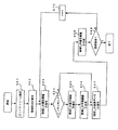
本実施の形態では、いままで述べたいろいろな動画像符号化装置によって生成される符号化ビットストリームを復号する動画像復号装置を説明する。図25に復号装置の構成を示す。同図において、43はビットストリーム解析部、44は領域形状復号部、45は属性情報復号部、46は画像データ復号部、47は動き情報復号部、48は動きパラメータ、49は動き補償部、50は予測画像、51は画像復元部、52は外部メモリ、53は再生画像である。
In the present embodiment, a video decoding device that decodes encoded bitstreams generated by the various video encoding devices described so far will be described. FIG. 25 shows the configuration of the decoding device. In the figure, 43 is a bit stream analysis unit, 44 is a region shape decoding unit, 45 is an attribute information decoding unit, 46 is an image data decoding unit, 47 is a motion information decoding unit, 48 is a motion parameter, 49 is a motion compensation unit, 50 is a predicted image, 51 is an image restoration unit, 52 is an external memory, and 53 is a reproduced image.
この復号装置は、画像フレームまたは画像フレーム中の部分画像(以下「画像フレーム等」という)に関して領域分割状態を表す領域形状情報、所定の方法により符号化された各領域の画像データ、各領域の属性情報、各領域の動き情報とからなる符号化ビットストリームを復号し、領域画像を復元し、画像フレーム等を再生する。 The decoding apparatus includes region shape information indicating a region division state regarding an image frame or a partial image in the image frame (hereinafter referred to as “image frame or the like”), image data of each region encoded by a predetermined method, An encoded bit stream including attribute information and motion information of each area is decoded, an area image is restored, and an image frame or the like is reproduced.
本実施の形態の場合、符号化の過程で正方形以外の領域が発生しているため、領域形状情報の記述方法は従来一般的なものと異なる。本実施の形態で採用される記述方法は、i)各領域の頂点の座標の明示、ii)符号化の際に領域を分割および統合したときの処理過程の明示、などによる。ii)の方法の場合、例えば、任意のi,jについて第i分割ステージにおいて分割された領域の番号、および第j統合ステージにおいて統合された領域の番号を記述しておく。復号装置では符号化装置同様、まず図6のごとく第0分割ステージを行い、以降符号化装置とまったく同じ手順を辿ることで最終的な分割状態を復元することができる。ii)の方法の場合、座標データを直接記述するよりも一般にデータ量が少ない。 In the case of the present embodiment, since a region other than a square is generated in the encoding process, the region shape information description method is different from the conventional one. The description method employed in this embodiment is based on i) clarification of the coordinates of the vertices of each region, ii) clarification of the processing process when the regions are divided and integrated at the time of encoding, and the like. In the case of the method ii), for example, the numbers of the areas divided in the i-th division stage and the numbers of the areas integrated in the j-th integration stage for arbitrary i and j are described. Similar to the encoding apparatus, the decoding apparatus first performs the 0th division stage as shown in FIG. 6, and can then restore the final division state by following exactly the same procedure as the encoding apparatus. In the case of the method ii), the amount of data is generally smaller than that in which coordinate data is directly described.
図26はこの復号装置の動作を示すフローチャートである。符号化ビットストリーム11は、まずビットストリーム解析部43に入力され、ビット列から符号化データへの変換が行われる(S61)。符号化データのうち、領域形状情報が領域形状復号部44において復号され、上述の方法で画像フレーム等の領域分割状態が復元される(S62)。領域が復元されたことにより、以降のビットストリーム中に符号化されている領域情報の符号化順序が特定される。各領域をSnとする。
FIG. 26 is a flowchart showing the operation of this decoding apparatus. The encoded
次いで、符号化順序に従って、ビットストリームから順次各領域のデータが復号される。まず領域Snの属性情報が属性情報復号部45で復号され、領域の符号化モード情報などが復号される(S63)。ここで、インターモード(フレーム間符号化モード)、すなわち予測誤差信号が符号化されているモードであれば(S64)、動き情報復号部47において動きパラメータ48が復号される(S65)。動きパラメータ48は動き補償部49に送られる。動き補償部49はこれに基づいて外部メモリ52に蓄積される参照画像中の予測画像に相当するメモリアドレスを計算し、外部メモリ52から予測画像50を取り出す(S66)。次いで、画像データ復号部46において領域Snの画像データが復号される(S67)。インターモードの場合、復号された画像データと予測画像50とを加算することによって最終的な領域Snの再生画像が得られる。
Next, the data of each region is sequentially decoded from the bit stream according to the encoding order. Attribute information of the first region S n is decoded by the
一方、イントラモード(フレーム内符号化モード)の場合は、復号された画像データがそのまま最終的な領域Snの再生画像53となる。再生画像は以降の予測画像生成のための参照画像として利用されるため、外部メモリ52に書き込まれる。これらの判断および再生画像の復元は画像復元部51で行われる(S68)。
On the other hand, in the case of intra mode (intra-frame coding mode), decoded image data as a reproduced
一連の処理は、画像フレーム等に含まれる全領域について行われた時点で終了する。以降の他の画像フレーム等についても同様の処理を施せばよい。 A series of processing ends when it is performed for all areas included in an image frame or the like. Similar processing may be applied to other image frames thereafter.
実施の形態9.
本実施の形態では、実施の形態1で説明した符号化部7の具体的な一構成例を示すことにする。
In the present embodiment, a specific configuration example of the
図29は、本実施の形態における符号化部7の内部構成を示したブロック構成図である。図29において、201は領域形状情報符号化部、202は領域属性情報符号化部、203は領域画像信号符号化部、204は領域動き情報符号化部、205はモード選択情報である。図29に示したように、符号化部7は、対応する領域毎の入力信号すなわち領域形状情報3、領域属性情報6、領域画像信号4及び領域動き情報5を符号化して、符号化処理後のデータを符号化データ11の一部として出力する。本実施の形態では、領域画像信号符号化部203の構成のみ着目して説明することとし、その他の符号化部201,202,204については構成を限定しないものとする。なお、実施の形態1では、暫定符号化部22においても領域データ(画像信号、動き情報、属性情報)の符号化を実施する。これは、領域分割の過程で行われる符号化処理であり、その結果は、符号化ビットストリームを出力するためでなく、統合処理のコストを計算するための符号量と符号化歪みの算出に用いられる。しかしながら、領域の画像信号に関しては領域画像信号符号化部203と全く同じ符号化処理を行うものとする。
FIG. 29 is a block configuration diagram showing an internal configuration of the
図30は、本実施の形態における領域画像信号符号化部203の内部構成を示したブロック構成図である。図30において、206はスイッチ、207は第1の領域画像信号符号化部、208は第2の領域画像信号符号化部、209は第3の領域画像信号符号化部である。図30に示したように、本実施の形態における領域画像信号符号化部203は、3通りの符号化手段を備え、これをモード選択情報205によって切り替える構成となっている。なお、モード選択情報205は、図1から明らかなように領域分割部2から送られてくる領域の属性情報6の一部の情報である。
FIG. 30 is a block configuration diagram showing an internal configuration of region image
図31は、図30における第1及び第2の領域画像信号符号化部207,208の内部構成を示した図である。図31において、210は小領域生成部、211は平均値分離部、212は小領域の平均値、213は正規化部、214は正規化係数としての標準偏差、215は正規化ベクトル、216は平均値を量子化するスカラ量子化部、217は標準偏差を量子化するスカラ量子化部、218は正規化ベクトルを符号化するベクトル量子化部である。各符号化部207,208は、請求項に係る第2の領域画像信号符号化部に相当し、領域を均一な大きさの小領域に分割して、その小領域毎に含まれる全画素の画素値の平均値を分離して正規化を行ったデータに対してベクトル量子化を行い、その小領域毎に求めた平均値、正規化係数及びベクトル量子化による符号化データを符号化する。また、各符号化部207,208は、特公昭63−41253号公報(以下、「文献1」)に開示された平均値分離正規化ベクトル量子化の処理を行う手段である。各符号化部207,208の相違はただ一つで、第1の領域画像信号符号化部207は、4画素×4画素の正方ブロックを小領域として定義している点で、8画素×8画素の正方ブロックを小領域として定義している第2の領域画像信号符号化部208と異なっている。すなわち、第1の領域画像信号符号化部207は、領域画像信号をより細かく小領域に分割して符号化することになる。本実施の形態では、第2の領域画像信号符号化部としてそれぞれ4画素×4画素又は8画素×8画素の小領域に分割する2つの構成要素を設けたが、この構成要素の数及び分割単位はこれに限られたものではない。
FIG. 31 is a diagram showing an internal configuration of first and second region image
次に、本実施の形態における第1及び第2の領域画像信号符号化部207,208の動作について説明するが、上記のように各符号化部207,208は、分割単位が異なるだけなので、図32に示したフローチャートに基づき小領域をN×N画素のブロックとして一括して説明する。
Next, the operation of the first and second region image
まず、小領域生成部210は、入力領域画像信号4をN×N画素のブロックで定義される小領域に分割する(S101)。平均値分離部211は、分割して生成された各小領域の平均値の計算を行う。このとき、各小領域画像をS、各小領域画像に含まれる画素数をK(=N×N)、小領域画像Sの各画素値をsi(i=1,2,・・,K)とすると、平均値mは、式(3)で算出される。
次に、正規化部213は、式(3)によって平均値の分離をした後の信号から標準偏差σを次式(4)によって算出する(S103)。
図33は、図30における第3の領域画像信号符号化部209の内部構成を示した図である。図33において、219は平均値分離部、220は領域の平均値、221は小領域生成部、222は正規化部、223は正規化係数としての標準偏差、224は正規化ベクトル、225は平均値を量子化するスカラ量子化部、226は標準偏差を量子化するスカラ量子化部、227は正規化ベクトルを符号化するベクトル量子化部である。第3の領域画像信号符号化部209は、請求項に係る第1の領域画像信号符号化部に相当し、領域内の全画素の画素値の平均値を算出し、その算出した平均値と、当該平均値に基づき当該領域を均一な大きさに分割した小領域毎に求めた正規化係数及びベクトル量子化とによる符号化データを符号化する。また、第3の領域画像信号符号化部209は、文献1に開示された平均値分離正規化ベクトル量子化の処理をベースとしながら平均値の分離を小領域の単位で行うのではなく領域の単位で行うことを特徴としている。これによって、領域のサイズが大きい場合、当該領域を小領域に分割し、小領域毎に算出した平均値により分離した後に符号化するのに比較して、どんなに領域が大きくても領域毎にただ一つの平均値のみを符号化すればよいので、符号量を削減した符号化を実現することができる。特に、例えば絵柄が平坦な領域内では、領域の平均値一つで小領域毎の平均値を代用してもほぼ十分な精度で領域画像を復元させることができるので非常に効果的である。
FIG. 33 is a diagram showing an internal configuration of the third region image
次に、本実施の形態における第3の領域画像信号符号化部209の動作について図34に示したフローチャートに基づき説明する。
Next, the operation of the third region image
平均値分離部219は、領域の平均値の計算を行う。領域画像をO、領域画像Oに含まれる画素数をK、領域画像Oの各画素値をoi(i=1,2,・・,K)とすると、平均値mは、式(6)で算出される。
小領域生成部221は、平均値の分離がされた領域画像信号をN×N画素のブロックで定義される小領域に分割する(S108)。
The small
正規化部222は、次式(7)によって小領域S毎に標準偏差σを算出する(S109)。
以上、本実施の形態における符号化部7によれば、3つの符号化モードを切り替えて符号化を実施することができ、領域の局所的な性質に合わせた符号化を行うことができる。例えば、領域内の絵柄が複雑な場合、動きが複雑で予測誤差画像の分散が大きい場合などには比較的細かい小領域を単位とした第1又は第2の領域画像信号符号化部207,208などを有効に作用させればよい。一方、絵柄が平坦な領域については、上述したように符号量を抑えることによって符号化効率の低下を抑止するために第3の領域画像信号符号化部209を有効に作用させればよい。本実施の形態によれば、領域画像信号の性質に応じて効率よく符号化をすることができる。
As described above, according to the
実施の形態10.
本実施の形態では、実施の形態8で説明した画像復号装置における画像データ復号部の具体的な一構成例を示すことにする。
In the present embodiment, a specific configuration example of the image data decoding unit in the image decoding apparatus described in the eighth embodiment will be shown.
図35は、本実施の形態における画像データ復号部46の内部構成を示したブロック構成図である。図35において、301は領域画像符号化データ、302はモード選択情報、303はスイッチ、304は第1の領域画像データ復号部、305は第2の領域画像データ復号部、306は第3の領域画像データ復号部、307は復号領域画像データである。図35に示したように、本実施の形態における画像データ復号部46は、3通りの復号手段を備え、これをモード選択情報302によって切り替える構成となっている。なお、モード選択情報302は、属性情報復号部45から出力される属性情報に含まれる情報である。
FIG. 35 is a block configuration diagram showing an internal configuration of the image
図36は、図35における第1及び第2の領域画像信号復号部304,305の内部構成を示した図である。図35において、308は量子化された小領域の平均値、309は量子化された標準偏差、310は量子化されたベクトル、311は小領域の平均値を逆量子化するスカラ逆量子化部(平均値復号部)、312は標準偏差を逆量子化するスカラ逆量子化部(正規化係数復号部)、313はベクトルを逆量子化するベクトル逆量子化部、314は乗算部、315は加算部、316は領域生成部である。各復号部304,305は、請求項に係る第2の領域画像信号復号部に相当し、個々の領域を均一な大きさに分割した各小領域に対応した平均値、正規化係数及びベクトル量子化による符号化データを復号するための手段である。また、文献1に開示された平均値分離正規化ベクトル量子化によって得られた領域画像符号化データを復号する。各復号部304,305の相違はただ一つで、第1の領域画像信号復号部304は、4画素×4画素の正方ブロックを小領域として定義している点で、8画素×8画素の正方ブロックを小領域として定義している第2の領域画像信号復号部305と異なっている。すなわち、第1の領域画像信号復号部304は、領域画像信号をより細かく等分割された小領域毎にベクトル量子化された符号化データを復号することになる。本実施の形態では、第2の領域画像信号復号部としてそれぞれ4画素×4画素又は8画素×8画素の小領域を扱う2つの構成要素を設けたが、この構成要素の数及び分割単位はこれに限られたものではなく、送られてくる符号化データに対応して設けられることになる。
FIG. 36 is a diagram showing the internal configuration of the first and second region image
次に、本実施の形態における第1及び第2の領域画像信号復号部304,305の動作について説明するが、上記のように各復号部304,305は、分割単位が異なるだけなので、図37に示したフローチャートに基づき小領域画像の画素値をS、各小領域画像に含まれる画素数をK(=N×N画素)として一括して説明する。
Next, the operation of the first and second region image
スカラ逆量子化部311は、小領域Sの平均値を逆量子化することで復号する(S201)。スカラ逆量子化部312は、小領域Sの標準偏差を逆量子化することで復号する(S202)。ベクトル逆量子化部313は、小領域Sのベクトルを逆量子化することで復号する(S203)。乗算部314は、ベクトル逆量子化部313により出力されたベクトルX(=[x1,x2,・・・,xk])に復号された標準偏差σを乗ずる(S204)。そして、加算部315は、乗算部314により出力されたベクトルσX(=[σx1,σx2,・・・,σxk])に復号された小領域の平均値mを加算する(S205)。この結果、小領域Sの画像信号(=[s1,s2,・・・,sk])を復元する。以上のS201〜S205の処理を全ての小領域に対する復号が終了するまで繰り返し行う(S206)。領域生成部316は、復号された小領域を集めて復号領域画像データを生成する。
The scalar
以上の処理により、領域画像信号を小領域に分割し、小領域毎に平均値を分離し、小領域の標準偏差により正規化したデータをベクトル量子化して得られた領域画像符号化データを復号することができる。 Through the above processing, the region image signal is divided into small regions, the average value is separated for each small region, and the region image encoded data obtained by vector quantization of the data normalized by the standard deviation of the small region is decoded. can do.
図38は、図35における第3の領域画像信号復号部306の内部構成を示した図である。図38において、317は量子化された領域の平均値、318は量子化された標準偏差、319は量子化されたベクトル、320は領域の平均値を逆量子化するスカラ逆量子化部(平均値復号部)、321は標準偏差を逆量子化するスカラ逆量子化部(正規化係数復号部)、322はベクトルを逆量子化するベクトル逆量子化部、323は乗算部、324は加算部、325は領域生成部である。第3の領域画像信号復号部306は、請求項に係る第1の領域画像信号復号部に相当し、個々の領域毎に対応した平均値と、個々の領域を均一な大きさに分割した各小領域に対応した正規化係数及びベクトル量子化とによる符号化データを復号する。また、第3の領域画像信号復号部306は、文献1に開示された平均値分離正規化ベクトル量子化の処理をベースとして量子化されたベクトルを量子化する。なお、第3の領域画像信号復号部306の構成要素は、領域を分割した4画素×4画素又は8画素×8画素の小領域の平均値ではなく領域の平均値を逆量子化するスカラ逆量子化部320を除いて図36に示した第1及び第2の領域画像信号復号部304,305と同じである。すなわち、第3の領域画像信号復号部306は、平均値の復号を小領域毎に行うのではなく領域毎に行うことを特徴としている。これによって、符号化側で平均値の分離を小領域の単位で行うのではなく領域の単位で行い、領域毎に一つの平均値を符号化した場合の領域画像を復号することができる。特に、例えば絵柄が平坦な領域内では、小領域毎の平均値を領域の平均値一つで代用することによってより少ない符号量で復元することができ、また、このようにしても十分な領域画像を得ることができる。
FIG. 38 is a diagram showing an internal configuration of the third region image
次に、本実施の形態における第3の領域画像信号復号部306の動作について図39に示したフローチャートに基づき説明する。
Next, the operation of third region image
スカラ逆量子化部320は、領域Oの平均値を逆量子化することで復号する(S207)。ここで復号された平均値mは、当該領域内の全ての小領域を復号する際に各小領域の平均値の代わりに用いられる。続いて、スカラ逆量子化部321は、量子化された小領域Sの標準偏差を逆量子化することで復号する(S208)。ベクトル逆量子化部322は、量子化された小領域Sのベクトルを逆量子化することで復号する(S209)。乗算部323は、ベクトル逆量子化部322により逆量子化されたベクトルX(=[x1,x2,・・・,xk])に復号された小領域Sの標準偏差σを乗ずる(S210)。そして、加算部324は、乗算部323により出力されたベクトルσX(=[σx1,σx2,・・・,σxk])に領域0の平均値mを加算する(S211)。この結果、小領域Sの画像信号(=[s1,s2,・・・,sk])を復元する。以上のS208〜S211の処理を全ての小領域に対する復号が終了するまで繰り返し行う(S212)。領域生成部325は、復号された小領域を集めて復号領域画像データを生成する。以上のようにして各領域の復号領域画像データ307を得ることができる。
The scalar
本実施の形態における画像データ復号部46によれば、3つの復号モードを切り替えて復号を実施することができ、領域の局所的な性質に合わせて符号化された領域画像を復号することができる。
According to the image
1 入力画像、2 領域分割部、3 領域形状情報、4 領域画像信号、5 領域動き情報、6 領域属性情報、7 符号化部、8 局所復号画像、9 メモリ、10 参照画像、11 符号化ビットストリーム、12 分割処理部、13 初期分割形状情報、14 統合処理部、15 均等分割部、16 アクティビティ算出部、17 アクティビティ、18 分割判定部、19 分割状態指示信号、20 ラベリング部、21 近傍領域設定部、22 暫定符号化部、23 復号部、24 符号化歪み算出部、25 評価値算出部、26 評価値算出に用いる定数、27 統合判定部、28 統合処理反復指示信号、29 クラス識別部、30 クラス識別子、31 分割判定部、32 特徴量メモリ、33 特徴合致度算出部、34 クラス決定部、35 分割判定部、36 分割処理反復指示信号、37 量子化パラメータ設定部、38 量子化パラメータ、39 暫定符号化部、40 動き補償予測コスト算出部、41 動き補償予測コスト、42 暫定符号化部、43 ビットストリーム解析部、44 領域形状復号部、45 属性情報復号部、46 画像データ復号部、47 動き情報復号部、48 動きパラメータ、49 動き補償部、50 予測画像、51 画像復元部、52 外部メモリ、53 再生画像、101 差分器、102 予測信号、103 予測誤差信号、104 符号化部、105 符号化データ、106 復号部、107 復号された予測誤差信号、108 加算器、109 局所復号画像信号、110 メモリ、111 予測部、112 動きベクトル、113 領域分割部、114 予測部 、115 領域決定部 、116 符号化モード情報、117 動きベクトル、118 符号化部 、119 符号化データ、201 領域形状情報符号化部、202 領域属性情報符号化部、203 領域画像信号符号化部、204 領域動き情報符号化部、205 モード選択情報、206 スイッチ、207 第1の領域画像信号符号化部、208 第2の領域画像信号符号化部、209 第3の領域画像信号符号化部、210 小領域生成部、211 平均値分離部、212 小領域の平均値、213 正規化部、214 標準偏差、215 正規化ベクトル、216 スカラ量子化部、217 スカラ量子化部、218 ベクトル量子化部、219 平均値分離部、220 領域の平均値、221 小領域生成部、222 正規化部、223 標準偏差、224 正規化ベクトル、225 スカラ量子化部、226 スカラ量子化部、227 ベクトル量子化部、301 領域画像符号化データ、302 モード選択情報、303 スイッチ、304 第1の領域画像データ復号部、305 第2の領域画像データ復号部、306 第3の領域画像データ復号部、307 復号領域画像データ、308 小領域の平均値、309 標準偏差、310 ベクトル、311 スカラ逆量子化部(平均値復号部)、312 スカラ逆量子化部(正規化係数復号部)、313 ベクトル逆量子化部、314 乗算部、315 加算部、316 領域生成部、317 領域の平均値、318 標準偏差、319 ベクトル、320 スカラ逆量子化部(平均値復号部)、321 スカラ逆量子化部(正規化係数復号部)、322 ベクトル逆量子化部、323 乗算部、324 加算部、325 領域生成部。 1 input image, 2 region dividing unit, 3 region shape information, 4 region image signal, 5 region motion information, 6 region attribute information, 7 encoding unit, 8 local decoded image, 9 memory, 10 reference image, 11 encoded bit Stream, 12 division processing unit, 13 initial division shape information, 14 integration processing unit, 15 equal division unit, 16 activity calculation unit, 17 activity, 18 division determination unit, 19 division state instruction signal, 20 labeling unit, 21 neighborhood region setting Unit, 22 provisional encoding unit, 23 decoding unit, 24 encoding distortion calculation unit, 25 evaluation value calculation unit, 26 constant used for evaluation value calculation, 27 integration determination unit, 28 integration processing repetition instruction signal, 29 class identification unit, 30 class identifier, 31 division determination unit, 32 feature amount memory, 33 feature match degree calculation unit, 34 class determination unit, 35 division Determination unit, 36 division processing repetition instruction signal, 37 quantization parameter setting unit, 38 quantization parameter, 39 provisional encoding unit, 40 motion compensation prediction cost calculation unit, 41 motion compensation prediction cost, 42 provisional encoding unit, 43 bits Stream analysis unit, 44 area shape decoding unit, 45 attribute information decoding unit, 46 image data decoding unit, 47 motion information decoding unit, 48 motion parameter, 49 motion compensation unit, 50 predicted image, 51 image restoration unit, 52 external memory, 53 reproduced image, 101 differentiator, 102 prediction signal, 103 prediction error signal, 104 encoding unit, 105 encoded data, 106 decoding unit, 107 decoded prediction error signal, 108 adder, 109 locally decoded image signal, 110 Memory, 111 prediction unit, 112 motion vector, 113 region division unit, 114 prediction , 115 region determination unit, 116 encoding mode information, 117 motion vector, 118 encoding unit, 119 encoded data, 201 region shape information encoding unit, 202 region attribute information encoding unit, 203 region image signal encoding unit , 204 region motion information encoding unit, 205 mode selection information, 206 switch, 207 first region image signal encoding unit, 208 second region image signal encoding unit, 209 third region image signal encoding unit, 210 Small region generation unit, 211 Average value separation unit, 212 Small region average value, 213 Normalization unit, 214 Standard deviation, 215 Normalization vector, 216 Scalar quantization unit, 217 Scalar quantization unit, 218 Vector quantization unit 219 Average value separation unit, 220 region average value, 221 small region generation unit, 222 normalization unit, 223 standard deviation 224 normalized vector, 225 scalar quantization unit, 226 scalar quantization unit, 227 vector quantization unit, 301 region image encoded data, 302 mode selection information, 303 switch, 304 first region image data decoding unit, 305 Second region image data decoding unit, 306 third region image data decoding unit, 307 decoded region image data, 308 average value of small region, 309 standard deviation, 310 vector, 311 scalar inverse quantization unit (average value decoding unit) 312 scalar dequantization unit (normalization coefficient decoding unit), 313 vector dequantization unit, 314 multiplication unit, 315 addition unit, 316 region generation unit, 317 region average value, 318 standard deviation, 319 vector, 320 Scalar inverse quantization unit (average value decoding unit), 321 Scalar inverse quantization unit (normalized coefficient decoding unit), 22 vector inverse quantization section, 323 multiplying unit, 324 adding section, 325 area generator.
Claims (4)
前記符号化データを受信する入力手段と、
前記受信した領域形状情報に基づいて、画像の全ての領域の形状を復元する領域形状復元手段と、
受信した前記予測画像を生成するためのそれぞれの領域毎の情報と、予測誤差信号を復元するための前記単位画像ブロック毎の情報とから、領域に対応する符号化データを復号するデータ復号手段と、
を備えることを特徴とする画像復号装置。 Each region has a different region shape and is encoded by dividing a plurality of regions formed by connecting a set of unit image blocks, and each region for generating a predicted image and region shape information for each image In an image decoding apparatus for decoding encoded data of an image including information for each unit and information for each unit image block for restoring a prediction error signal,
Input means for receiving the encoded data;
Based on the received area shape information, area shape restoring means for restoring the shape of all areas of the image,
Data decoding means for decoding encoded data corresponding to a region from the information for each region for generating the received predicted image and the information for each unit image block for restoring a prediction error signal; ,
An image decoding apparatus comprising:
前記符号化データを受信する入力ステップと、
前記受信した領域形状情報に基づいて、画像の全ての領域の形状を復元する領域形状復元ステップと、
受信した前記予測画像を生成するためのそれぞれの領域毎の情報と、予測誤差信号を復元するための前記単位画像ブロック毎の情報とから、領域に対応する符号化データを復号するデータ復号ステップと、
を含むことを特徴とする画像復号方法。 Each region has a different region shape and is encoded by dividing a plurality of regions formed by connecting a set of unit image blocks, and each region for generating a predicted image and region shape information for each image Implemented in an image decoding apparatus that decodes encoded data of an image, including information for each unit and information for each unit image block for restoring a prediction error signal,
Receiving the encoded data; and
Based on the received area shape information, an area shape restoring step for restoring the shape of all areas of the image;
A data decoding step of decoding encoded data corresponding to a region from the information for each region for generating the received predicted image and the information for each unit image block for restoring a prediction error signal; ,
An image decoding method comprising:
画像の所定単位画像ブロックへの最初の分割、及びその後の単位画像ブロックのセットの連結により、それぞれの領域の形状を形成し、画像における全ての領域の形状を形成し、画像における全ての領域の形状を特定する情報として領域形状情報を生成する領域形状生成手段と、
予測画像を生成するためのそれぞれの領域毎の情報を決定し、予測誤差信号を復元するための前記単位画像ブロック毎の情報を生成する予測手段と、
それぞれの画像毎の前記領域形状情報と、予測画像を生成するためのそれぞれの領域毎の情報と、予測誤差信号を復元するための前記単位画像ブロック毎の情報とを符号化する符号化手段と、
を備えることを特徴とする画像符号化装置。 In an image encoding device that encodes an image by dividing a plurality of regions each having a different region shape and formed by connecting a set of unit image blocks,
By first dividing the image into predetermined unit image blocks, and then concatenating a set of unit image blocks, the shape of each region is formed, the shape of all regions in the image is formed, and all regions in the image are Area shape generating means for generating area shape information as information for specifying the shape;
Predicting means for determining information for each region for generating a predicted image and generating information for each unit image block for restoring a prediction error signal;
Encoding means for encoding the region shape information for each image, information for each region for generating a prediction image, and information for each unit image block for restoring a prediction error signal; ,
An image encoding device comprising:
画像の所定単位画像ブロックへの最初の分割、及びその後の単位画像ブロックのセットの連結により、それぞれの領域の形状を形成し、画像における全ての領域の形状を形成し、画像における全ての領域の形状を特定する情報として領域形状情報を生成する領域形状生成ステップと、
予測画像を生成するためのそれぞれの領域毎の情報を決定し、予測誤差信号を復元するための前記単位画像ブロック毎の情報を生成する予測ステップと、
それぞれの画像毎の前記領域形状情報と、予測画像を生成するためのそれぞれの領域毎の情報と、予測誤差信号を復元するための前記単位画像ブロック毎の情報とを符号化する符号化ステップと、
を含むことを特徴とする画像符号化方法。 Implemented in an image encoding apparatus that encodes an image by dividing a plurality of regions each having a different region shape and formed by connecting a set of unit image blocks,
By first dividing the image into predetermined unit image blocks, and then concatenating a set of unit image blocks, the shape of each region is formed, the shape of all regions in the image is formed, and all regions in the image are A region shape generation step for generating region shape information as information for specifying a shape;
A prediction step of determining information for each region for generating a prediction image and generating information for each unit image block for restoring a prediction error signal;
An encoding step for encoding the region shape information for each image, information for each region for generating a prediction image, and information for each unit image block for restoring a prediction error signal; ,
An image encoding method comprising:
Priority Applications (1)
| Application Number | Priority Date | Filing Date | Title |
|---|---|---|---|
| JP2009175353A JP2009247019A (en) | 1997-04-24 | 2009-07-28 | Image decoding apparatus, image decoding method, image encoding apparatus and image encoding method |
Applications Claiming Priority (3)
| Application Number | Priority Date | Filing Date | Title |
|---|---|---|---|
| JP10707297 | 1997-04-24 | ||
| JP26142097 | 1997-09-26 | ||
| JP2009175353A JP2009247019A (en) | 1997-04-24 | 2009-07-28 | Image decoding apparatus, image decoding method, image encoding apparatus and image encoding method |
Related Parent Applications (1)
| Application Number | Title | Priority Date | Filing Date |
|---|---|---|---|
| JP2008203151A Division JP4514818B2 (en) | 1997-04-24 | 2008-08-06 | Video decoding device |
Related Child Applications (1)
| Application Number | Title | Priority Date | Filing Date |
|---|---|---|---|
| JP2010231148A Division JP2011010371A (en) | 1997-04-24 | 2010-10-14 | Apparatus for moving image decoding |
Publications (1)
| Publication Number | Publication Date |
|---|---|
| JP2009247019A true JP2009247019A (en) | 2009-10-22 |
Family
ID=26447144
Family Applications (8)
| Application Number | Title | Priority Date | Filing Date |
|---|---|---|---|
| JP04318198A Expired - Lifetime JP3835919B2 (en) | 1997-04-24 | 1998-02-25 | Video decoding device |
| JP2006183358A Expired - Lifetime JP4514734B2 (en) | 1997-04-24 | 2006-07-03 | Video decoding device |
| JP2008203152A Expired - Lifetime JP4514819B2 (en) | 1997-04-24 | 2008-08-06 | Video decoding device |
| JP2008203151A Expired - Lifetime JP4514818B2 (en) | 1997-04-24 | 2008-08-06 | Video decoding device |
| JP2009175353A Pending JP2009247019A (en) | 1997-04-24 | 2009-07-28 | Image decoding apparatus, image decoding method, image encoding apparatus and image encoding method |
| JP2010231148A Pending JP2011010371A (en) | 1997-04-24 | 2010-10-14 | Apparatus for moving image decoding |
| JP2011279576A Pending JP2012085344A (en) | 1997-04-24 | 2011-12-21 | Moving image decoding device |
| JP2011279577A Expired - Lifetime JP5138086B2 (en) | 1997-04-24 | 2011-12-21 | Video decoding device |
Family Applications Before (4)
| Application Number | Title | Priority Date | Filing Date |
|---|---|---|---|
| JP04318198A Expired - Lifetime JP3835919B2 (en) | 1997-04-24 | 1998-02-25 | Video decoding device |
| JP2006183358A Expired - Lifetime JP4514734B2 (en) | 1997-04-24 | 2006-07-03 | Video decoding device |
| JP2008203152A Expired - Lifetime JP4514819B2 (en) | 1997-04-24 | 2008-08-06 | Video decoding device |
| JP2008203151A Expired - Lifetime JP4514818B2 (en) | 1997-04-24 | 2008-08-06 | Video decoding device |
Family Applications After (3)
| Application Number | Title | Priority Date | Filing Date |
|---|---|---|---|
| JP2010231148A Pending JP2011010371A (en) | 1997-04-24 | 2010-10-14 | Apparatus for moving image decoding |
| JP2011279576A Pending JP2012085344A (en) | 1997-04-24 | 2011-12-21 | Moving image decoding device |
| JP2011279577A Expired - Lifetime JP5138086B2 (en) | 1997-04-24 | 2011-12-21 | Video decoding device |
Country Status (5)
| Country | Link |
|---|---|
| US (5) | US6633611B2 (en) |
| JP (8) | JP3835919B2 (en) |
| DE (1) | DE19803781C2 (en) |
| FR (1) | FR2762699B1 (en) |
| SG (1) | SG65041A1 (en) |
Families Citing this family (112)
| Publication number | Priority date | Publication date | Assignee | Title |
|---|---|---|---|---|
| WO1998042134A1 (en) * | 1997-03-17 | 1998-09-24 | Mitsubishi Denki Kabushiki Kaisha | Image encoder, image decoder, image encoding method, image decoding method and image encoding/decoding system |
| US6633611B2 (en) * | 1997-04-24 | 2003-10-14 | Mitsubishi Denki Kabushiki Kaisha | Method and apparatus for region-based moving image encoding and decoding |
| US6529634B1 (en) * | 1999-11-08 | 2003-03-04 | Qualcomm, Inc. | Contrast sensitive variance based adaptive block size DCT image compression |
| KR100359115B1 (en) * | 2000-05-24 | 2002-11-04 | 삼성전자 주식회사 | Video coding method |
| JP4665372B2 (en) * | 2000-05-29 | 2011-04-06 | ソニー株式会社 | Image processing apparatus and method, communication system and method, and recording medium |
| TW515192B (en) | 2000-06-06 | 2002-12-21 | Noa Kk Off | Compression method of motion picture image data and system there for |
| US7085424B2 (en) | 2000-06-06 | 2006-08-01 | Kobushiki Kaisha Office Noa | Method and system for compressing motion image information |
| US8798166B2 (en) * | 2001-08-17 | 2014-08-05 | Broadcom Corporation | Video encoding scheme supporting the transport of audio and auxiliary information |
| AU2002230101A2 (en) * | 2001-01-30 | 2002-08-19 | Kabushiki Kaisha Office Noa | Moving picture information compressing method and its system |
| US7266150B2 (en) | 2001-07-11 | 2007-09-04 | Dolby Laboratories, Inc. | Interpolation of video compression frames |
| JP4752158B2 (en) * | 2001-08-28 | 2011-08-17 | 株式会社豊田中央研究所 | Environment complexity calculation device, environment recognition degree estimation device and obstacle alarm device |
| WO2003039163A1 (en) * | 2001-11-01 | 2003-05-08 | Kabushiki Kaisha Office Noa | Moving picture information compression method and system thereof |
| CN101448162B (en) | 2001-12-17 | 2013-01-02 | 微软公司 | Method for processing video image |
| DE10163084A1 (en) * | 2001-12-20 | 2003-07-17 | Infineon Technologies Ag | Electronic component and method for its production |
| US7003035B2 (en) | 2002-01-25 | 2006-02-21 | Microsoft Corporation | Video coding methods and apparatuses |
| US20040001546A1 (en) | 2002-06-03 | 2004-01-01 | Alexandros Tourapis | Spatiotemporal prediction for bidirectionally predictive (B) pictures and motion vector prediction for multi-picture reference motion compensation |
| US7944971B1 (en) * | 2002-07-14 | 2011-05-17 | Apple Inc. | Encoding video |
| US20040022322A1 (en) * | 2002-07-19 | 2004-02-05 | Meetrix Corporation | Assigning prioritization during encode of independently compressed objects |
| US8949922B2 (en) * | 2002-12-10 | 2015-02-03 | Ol2, Inc. | System for collaborative conferencing using streaming interactive video |
| US10554985B2 (en) | 2003-07-18 | 2020-02-04 | Microsoft Technology Licensing, Llc | DC coefficient signaling at small quantization step sizes |
| FR2872975A1 (en) * | 2004-07-06 | 2006-01-13 | Thomson Licensing Sa | METHOD AND DEVICE FOR CHOOSING AN ENCODING MODE |
| KR20070064598A (en) * | 2004-09-16 | 2007-06-21 | 톰슨 라이센싱 | Method and apparatus for fast mode decision for interframes |
| JP4804107B2 (en) * | 2004-12-14 | 2011-11-02 | キヤノン株式会社 | Image encoding apparatus, image encoding method and program thereof |
| JP4556694B2 (en) * | 2005-02-07 | 2010-10-06 | ソニー株式会社 | Encoding apparatus and method, recording medium, program, and image processing system |
| US8422546B2 (en) | 2005-05-25 | 2013-04-16 | Microsoft Corporation | Adaptive video encoding using a perceptual model |
| US7885335B2 (en) * | 2005-09-16 | 2011-02-08 | Sont Corporation | Variable shape motion estimation in video sequence |
| JP4828543B2 (en) | 2005-09-26 | 2011-11-30 | 三菱電機株式会社 | Video encoding apparatus and video decoding apparatus |
| US8149918B2 (en) * | 2005-11-10 | 2012-04-03 | Electronics And Telecommunications Research Institute | Method of estimating coded block pattern and method of determining block mode using the same for moving picture encoder |
| US7646922B2 (en) * | 2005-12-30 | 2010-01-12 | Honeywell International Inc. | Object classification in video images |
| US7974340B2 (en) | 2006-04-07 | 2011-07-05 | Microsoft Corporation | Adaptive B-picture quantization control |
| US8130828B2 (en) * | 2006-04-07 | 2012-03-06 | Microsoft Corporation | Adjusting quantization to preserve non-zero AC coefficients |
| US8059721B2 (en) | 2006-04-07 | 2011-11-15 | Microsoft Corporation | Estimating sample-domain distortion in the transform domain with rounding compensation |
| US7995649B2 (en) | 2006-04-07 | 2011-08-09 | Microsoft Corporation | Quantization adjustment based on texture level |
| US20070237237A1 (en) * | 2006-04-07 | 2007-10-11 | Microsoft Corporation | Gradient slope detection for video compression |
| US8503536B2 (en) | 2006-04-07 | 2013-08-06 | Microsoft Corporation | Quantization adjustments for DC shift artifacts |
| US8711925B2 (en) * | 2006-05-05 | 2014-04-29 | Microsoft Corporation | Flexible quantization |
| US20080025390A1 (en) * | 2006-07-25 | 2008-01-31 | Fang Shi | Adaptive video frame interpolation |
| US8363936B2 (en) | 2006-08-25 | 2013-01-29 | Thomson Licensing | Method and apparatus for reduced resolution partitioning |
| US9418450B2 (en) | 2006-08-31 | 2016-08-16 | Ati Technologies Ulc | Texture compression techniques |
| CA2664668C (en) * | 2006-10-10 | 2014-04-01 | Nippon Telegraph And Telephone Corporation | Intra prediction encoding control method and apparatus, program therefor, and storage medium which stores the program |
| JP2008141616A (en) * | 2006-12-04 | 2008-06-19 | Fujifilm Corp | Motion vector calculating apparatus, method and program, moving image compressing and recording device, and imaging apparatus |
| JP4885698B2 (en) * | 2006-12-20 | 2012-02-29 | 富士フイルム株式会社 | Motion vector calculation device, method and program, moving image compression recording device, and imaging device |
| US8238424B2 (en) | 2007-02-09 | 2012-08-07 | Microsoft Corporation | Complexity-based adaptive preprocessing for multiple-pass video compression |
| WO2008107943A1 (en) * | 2007-03-01 | 2008-09-12 | Nippon Telegraph And Telephone Corporation | Scalable encoding method and device, scalable decoding method and device, program thereof, and recording medium |
| CN101641956B (en) * | 2007-03-09 | 2011-10-12 | 杜比实验室特许公司 | Multi-frame motion extrapolation from a compressed video source |
| EP2129134B1 (en) | 2007-03-20 | 2018-06-27 | Fujitsu Limited | Time-varying image encoding method and device, and time-varying image decoding device |
| US20080240257A1 (en) * | 2007-03-26 | 2008-10-02 | Microsoft Corporation | Using quantization bias that accounts for relations between transform bins and quantization bins |
| US8498335B2 (en) | 2007-03-26 | 2013-07-30 | Microsoft Corporation | Adaptive deadzone size adjustment in quantization |
| US8243797B2 (en) | 2007-03-30 | 2012-08-14 | Microsoft Corporation | Regions of interest for quality adjustments |
| US8442337B2 (en) | 2007-04-18 | 2013-05-14 | Microsoft Corporation | Encoding adjustments for animation content |
| US8331438B2 (en) * | 2007-06-05 | 2012-12-11 | Microsoft Corporation | Adaptive selection of picture-level quantization parameters for predicted video pictures |
| TWI336588B (en) * | 2007-06-14 | 2011-01-21 | Novatek Microelectronics Corp | A focusing method, suitable for an image capturing apparatus using in an environment of low brightness and image capturing apparatus using the same |
| KR101681443B1 (en) * | 2007-10-16 | 2016-11-30 | 톰슨 라이센싱 | Methods and apparatus for video encoding and decoding geometrically partitioned super blocks |
| US20090154567A1 (en) * | 2007-12-13 | 2009-06-18 | Shaw-Min Lei | In-loop fidelity enhancement for video compression |
| JP2009147807A (en) * | 2007-12-17 | 2009-07-02 | Fujifilm Corp | Image processing apparatus |
| JP5188356B2 (en) * | 2008-02-28 | 2013-04-24 | ミツビシ・エレクトリック・リサーチ・ラボラトリーズ・インコーポレイテッド | Method for inverse tone mapping of an image in a decoder |
| RU2010132652A (en) * | 2008-03-07 | 2012-02-10 | Кабусики Кайся Тосиба (Jp) | METHOD AND DEVICE FOR VIDEO CODING / DECODING |
| US8189933B2 (en) | 2008-03-31 | 2012-05-29 | Microsoft Corporation | Classifying and controlling encoding quality for textured, dark smooth and smooth video content |
| US8948822B2 (en) * | 2008-04-23 | 2015-02-03 | Qualcomm Incorporated | Coordinating power management functions in a multi-media device |
| US8897359B2 (en) | 2008-06-03 | 2014-11-25 | Microsoft Corporation | Adaptive quantization for enhancement layer video coding |
| KR20090129926A (en) * | 2008-06-13 | 2009-12-17 | 삼성전자주식회사 | Method and apparatus for image encoding by dynamic unit grouping, and method and apparatus for image decoding by dynamic unit grouping |
| US8908763B2 (en) * | 2008-06-25 | 2014-12-09 | Qualcomm Incorporated | Fragmented reference in temporal compression for video coding |
| CN102113326A (en) | 2008-08-04 | 2011-06-29 | 杜比实验室特许公司 | Overlapped block disparity estimation and compensation architecture |
| US8948270B2 (en) | 2008-08-19 | 2015-02-03 | Qualcomm Incorporated | Power and computational load management techniques in video processing |
| US8964828B2 (en) | 2008-08-19 | 2015-02-24 | Qualcomm Incorporated | Power and computational load management techniques in video processing |
| US8503527B2 (en) | 2008-10-03 | 2013-08-06 | Qualcomm Incorporated | Video coding with large macroblocks |
| US8483285B2 (en) | 2008-10-03 | 2013-07-09 | Qualcomm Incorporated | Video coding using transforms bigger than 4×4 and 8×8 |
| US8634456B2 (en) * | 2008-10-03 | 2014-01-21 | Qualcomm Incorporated | Video coding with large macroblocks |
| US8619856B2 (en) * | 2008-10-03 | 2013-12-31 | Qualcomm Incorporated | Video coding with large macroblocks |
| EP2222086A1 (en) | 2009-02-18 | 2010-08-25 | EcoDisc Technology AG | Method and device for avoiding rounding errors after carrying out an inverse discrete orthogonal transformation |
| JP5133290B2 (en) * | 2009-03-31 | 2013-01-30 | 株式会社Kddi研究所 | Video encoding apparatus and decoding apparatus |
| BRPI1015982A2 (en) * | 2009-06-19 | 2016-04-19 | Mitsubishi Eletric Corp | image coding and image decoding devices and methods. |
| FR2947134A1 (en) * | 2009-06-23 | 2010-12-24 | France Telecom | METHODS OF ENCODING AND DECODING IMAGES, CODING AND DECODING DEVICES, DATA STREAMS AND CORRESPONDING COMPUTER PROGRAM. |
| KR20110017719A (en) * | 2009-08-14 | 2011-02-22 | 삼성전자주식회사 | Method and apparatus for video encoding, and method and apparatus for video decoding |
| KR101456498B1 (en) * | 2009-08-14 | 2014-10-31 | 삼성전자주식회사 | Method and apparatus for video encoding considering scanning order of coding units with hierarchical structure, and method and apparatus for video decoding considering scanning order of coding units with hierarchical structure |
| JP2011082801A (en) * | 2009-10-07 | 2011-04-21 | Fujitsu Ltd | Image processing apparatus, and image processing method |
| CN102577393B (en) * | 2009-10-20 | 2015-03-25 | 夏普株式会社 | Moving image coding device, moving image decoding device, moving image coding/decoding system, moving image coding method and moving image decoding method |
| KR101452713B1 (en) * | 2009-10-30 | 2014-10-21 | 삼성전자주식회사 | Method and apparatus for encoding and decoding coding unit of picture boundary |
| KR101484280B1 (en) * | 2009-12-08 | 2015-01-20 | 삼성전자주식회사 | Method and apparatus for video encoding by motion prediction using arbitrary partition, and method and apparatus for video decoding by motion compensation using arbitrary partition |
| KR20110112168A (en) * | 2010-04-05 | 2011-10-12 | 삼성전자주식회사 | Method and apparatus for video encoding based on internal bitdepth increment, method and apparatus for video decoding based on internal bitdepth increment |
| US9369736B2 (en) | 2010-04-05 | 2016-06-14 | Samsung Electronics Co., Ltd. | Low complexity entropy-encoding/decoding method and apparatus |
| WO2011126282A2 (en) | 2010-04-05 | 2011-10-13 | Samsung Electronics Co., Ltd. | Method and apparatus for encoding video by using transformation index, and method and apparatus for decoding video by using transformation index |
| WO2011126283A2 (en) | 2010-04-05 | 2011-10-13 | Samsung Electronics Co., Ltd. | Method and apparatus for encoding video based on internal bit depth increment, and method and apparatus for decoding video based on internal bit depth increment |
| US20130259121A1 (en) * | 2010-12-27 | 2013-10-03 | Nec Corporation | Video encoding device, video decoding device, video encoding method, video decoding method, and program |
| JP5622613B2 (en) * | 2011-02-25 | 2014-11-12 | 三菱電機株式会社 | Moving picture coding apparatus, moving picture coding method, and moving picture coding program |
| US8494290B2 (en) * | 2011-05-05 | 2013-07-23 | Mitsubishi Electric Research Laboratories, Inc. | Method for coding pictures using hierarchical transform units |
| JP5727873B2 (en) * | 2011-06-10 | 2015-06-03 | 日本放送協会 | Motion vector detection device, encoding device, and program thereof |
| JP5677576B2 (en) * | 2011-07-22 | 2015-02-25 | 株式会社日立製作所 | Video decoding method and video encoding method |
| US20130083852A1 (en) * | 2011-09-30 | 2013-04-04 | Broadcom Corporation | Two-dimensional motion compensation filter operation and processing |
| KR101625910B1 (en) * | 2011-10-19 | 2016-05-31 | 한국전자통신연구원 | Method and device for image processing by image division |
| JP5832263B2 (en) * | 2011-12-07 | 2015-12-16 | 株式会社日立国際電気 | Image coding apparatus and image coding method |
| US9014265B1 (en) * | 2011-12-29 | 2015-04-21 | Google Inc. | Video coding using edge detection and block partitioning for intra prediction |
| JP5779116B2 (en) * | 2012-02-07 | 2015-09-16 | 日本電信電話株式会社 | Image coding method, image coding apparatus, and image coding program |
| KR20130108948A (en) * | 2012-03-26 | 2013-10-07 | 한국전자통신연구원 | Image encoding method using adaptive preprocessing |
| US9332276B1 (en) | 2012-08-09 | 2016-05-03 | Google Inc. | Variable-sized super block based direct prediction mode |
| GB2503295B (en) * | 2012-08-13 | 2014-08-06 | Gurulogic Microsystems Oy | Encoder and method |
| EP2899974A4 (en) * | 2012-09-18 | 2016-03-09 | Nec Corp | Video coding device, video coding method, and video coding program |
| TW201419864A (en) * | 2012-11-13 | 2014-05-16 | Hon Hai Prec Ind Co Ltd | System and method for splitting an image |
| US9210424B1 (en) | 2013-02-28 | 2015-12-08 | Google Inc. | Adaptive prediction block size in video coding |
| CN104871544B (en) * | 2013-03-25 | 2018-11-02 | 麦克赛尔株式会社 | Coding method and code device |
| US9313493B1 (en) | 2013-06-27 | 2016-04-12 | Google Inc. | Advanced motion estimation |
| JP5719410B2 (en) * | 2013-07-25 | 2015-05-20 | 日本電信電話株式会社 | Image coding method, image coding apparatus, and image coding program |
| JP6221704B2 (en) * | 2013-12-05 | 2017-11-01 | Nttエレクトロニクス株式会社 | Encoding apparatus and block size selection method |
| JP6145084B2 (en) * | 2014-12-11 | 2017-06-07 | 日本電信電話株式会社 | Size determining method, size determining apparatus and computer program |
| JP5957513B2 (en) * | 2014-12-16 | 2016-07-27 | 株式会社日立製作所 | Video decoding method |
| FR3030976B1 (en) * | 2014-12-22 | 2018-02-02 | B<>Com | METHOD FOR ENCODING A DIGITAL IMAGE, DECODING METHOD, DEVICES AND COMPUTER PROGRAMS |
| US9807416B2 (en) | 2015-09-21 | 2017-10-31 | Google Inc. | Low-latency two-pass video coding |
| US10560702B2 (en) * | 2016-01-22 | 2020-02-11 | Intel Corporation | Transform unit size determination for video coding |
| WO2018092868A1 (en) | 2016-11-21 | 2018-05-24 | パナソニック インテレクチュアル プロパティ コーポレーション オブ アメリカ | Coding device, decoding device, coding method, and decoding method |
| WO2018092870A1 (en) * | 2016-11-21 | 2018-05-24 | パナソニック インテレクチュアル プロパティ コーポレーション オブ アメリカ | Coding device, decoding device, coding method, and decoding method |
| CN116320415A (en) | 2016-11-21 | 2023-06-23 | 松下电器(美国)知识产权公司 | Image encoding device and method, image decoding device and method |
| US10453221B2 (en) * | 2017-04-10 | 2019-10-22 | Intel Corporation | Region based processing |
Citations (12)
| Publication number | Priority date | Publication date | Assignee | Title |
|---|---|---|---|---|
| JPH06169449A (en) * | 1992-11-30 | 1994-06-14 | Mitsubishi Electric Corp | Picture band dividing and encoding device |
| JPH0738896A (en) * | 1993-06-28 | 1995-02-07 | Nippon Telegr & Teleph Corp <Ntt> | Dynamic image region dividing and encoding device |
| JPH07212760A (en) * | 1994-01-14 | 1995-08-11 | Nippon Telegr & Teleph Corp <Ntt> | Method for motion compensation prediction coding for moving picture |
| JPH07240922A (en) * | 1994-02-28 | 1995-09-12 | Kyocera Corp | Image encoder/recoder |
| JPH07264594A (en) * | 1994-03-23 | 1995-10-13 | Nippon Telegr & Teleph Corp <Ntt> | Motion compensative prediction encoding method for dynamic image |
| JPH07322251A (en) * | 1994-05-30 | 1995-12-08 | Fuji Electric Co Ltd | Image processing unit and data compression method |
| JPH0846968A (en) * | 1994-08-03 | 1996-02-16 | Nippon Telegr & Teleph Corp <Ntt> | Method and device for detecting hierarchical motion vector |
| JPH08214306A (en) * | 1994-10-31 | 1996-08-20 | Daewoo Electron Co Ltd | Video signal processing system |
| JPH08251583A (en) * | 1995-03-10 | 1996-09-27 | Sharp Corp | Image encoding device and image decoding device |
| JPH0993612A (en) * | 1995-09-22 | 1997-04-04 | Sanyo Electric Co Ltd | Image coding method using contour information |
| JPH09507347A (en) * | 1993-11-15 | 1997-07-22 | ナショナル・セミコンダクター・コーポレイション | Quad-tree WALSH conversion video / image coding |
| JP2000511366A (en) * | 1995-10-25 | 2000-08-29 | サーノフ コーポレイション | Apparatus and method for variable block size motion estimation based on quadrant tree |
Family Cites Families (64)
| Publication number | Priority date | Publication date | Assignee | Title |
|---|---|---|---|---|
| EP0290085B1 (en) | 1987-05-06 | 1996-03-20 | Philips Patentverwaltung GmbH | System for the transmission of video pictures |
| JP2886172B2 (en) | 1987-08-28 | 1999-04-26 | ブリテツシユ・テレコミユニケイシヨンズ・パブリツク・リミテツド・カンパニー | Signal coding |
| FR2628864B1 (en) | 1988-03-21 | 1990-06-15 | France Etat | METHOD FOR SEGMENTATION OF A FIELD OF SPEED VECTORS, IN PARTICULAR OF SPEEDS FOR MOVING POINTS OF AN IMAGE IN A SEQUENCE OF IMAGES |
| GB2223139B (en) * | 1988-08-31 | 1993-03-03 | Canon Kk | Automatic focusing apparatus |
| JPH07105949B2 (en) * | 1989-03-20 | 1995-11-13 | 松下電器産業株式会社 | Image motion vector detection device and shake correction device |
| JPH082107B2 (en) * | 1990-03-02 | 1996-01-10 | 国際電信電話株式会社 | Method and apparatus for moving picture hybrid coding |
| FR2664117B1 (en) * | 1990-06-29 | 1996-06-21 | Thomson Csf | CODING METHOD WITH ADJUSTABLE PARAMETERS OF A MOVEMENT FIELD IN A SEQUENCE OF MOVED IMAGES. |
| US5088397A (en) * | 1991-01-11 | 1992-02-18 | The Dupps Co. | Cast formed bi-metallic worm assembly |
| JP3068304B2 (en) * | 1992-01-21 | 2000-07-24 | 日本電気株式会社 | Video coding and decoding systems |
| US5596659A (en) | 1992-09-01 | 1997-01-21 | Apple Computer, Inc. | Preprocessing and postprocessing for vector quantization |
| FR2703802A1 (en) | 1993-04-07 | 1994-10-14 | Philips Electronique Lab | Apparatus for motion estimation between successive images of an animated image sequence subdivided into two-dimensional blocks of pixels. |
| US5436666A (en) * | 1993-05-21 | 1995-07-25 | Intel Corporation | Limited-domain motion estimation/compensation for video encoding/decoding |
| JPH0787448A (en) * | 1993-06-30 | 1995-03-31 | Victor Co Of Japan Ltd | Coding circuit and decoding circuit for digital video signal |
| GB9315775D0 (en) * | 1993-07-30 | 1993-09-15 | British Telecomm | Processing image data |
| JP2576771B2 (en) | 1993-09-28 | 1997-01-29 | 日本電気株式会社 | Motion compensation prediction device |
| US5453787A (en) * | 1993-12-10 | 1995-09-26 | International Business Machines Corporation | Variable spatial frequency chrominance encoding in software motion video compression |
| US5812198A (en) * | 1994-05-30 | 1998-09-22 | Ntt Mobile Communications Network, Inc. | Video coding decoding apparatus |
| US5594504A (en) * | 1994-07-06 | 1997-01-14 | Lucent Technologies Inc. | Predictive video coding using a motion vector updating routine |
| US5608458A (en) * | 1994-10-13 | 1997-03-04 | Lucent Technologies Inc. | Method and apparatus for a region-based approach to coding a sequence of video images |
| JPH08116540A (en) * | 1994-10-14 | 1996-05-07 | Sanyo Electric Co Ltd | Image coder and image decoder using area division |
| US5886743A (en) * | 1994-12-28 | 1999-03-23 | Hyundai Electronics Industries Co. Ltd. | Object-by information coding apparatus and method thereof for MPEG-4 picture instrument |
| US5799109A (en) * | 1994-12-29 | 1998-08-25 | Hyundai Electronics Industries Co., Ltd. | Object-by shape information compression apparatus and method and coding method between motion picture compensation frames |
| US6275532B1 (en) * | 1995-03-18 | 2001-08-14 | Sharp Kabushiki Kaisha | Video coding device and video decoding device with a motion compensated interframe prediction |
| JP3169783B2 (en) * | 1995-02-15 | 2001-05-28 | 日本電気株式会社 | Video encoding / decoding system |
| US5731840A (en) * | 1995-03-10 | 1998-03-24 | Kabushiki Kaisha Toshiba | Video coding/decoding apparatus which transmits different accuracy prediction levels |
| EP1802134A3 (en) * | 1995-03-15 | 2008-12-31 | Kabushiki Kaisha Toshiba | Moving picture coding and/or decoding systems |
| US5654771A (en) * | 1995-05-23 | 1997-08-05 | The University Of Rochester | Video compression system using a dense motion vector field and a triangular patch mesh overlay model |
| US5638130A (en) * | 1995-05-25 | 1997-06-10 | International Business Machines Corporation | Display system with switchable aspect ratio |
| EP0757334A3 (en) | 1995-07-07 | 1997-07-02 | Imec Vzw | Data compression method and apparatus |
| MY121607A (en) * | 1995-07-10 | 2006-02-28 | Hyundai Curitel Inc | Grid moving method of object image and apparatus using the same and compaction/motion estimation method using the same and apparatus thereof |
| US6023301A (en) | 1995-07-14 | 2000-02-08 | Sharp Kabushiki Kaisha | Video coding device and video decoding device |
| JP3358692B2 (en) | 1995-08-02 | 2002-12-24 | 日本電信電話株式会社 | Video block classification method and apparatus |
| WO1997009828A1 (en) * | 1995-09-06 | 1997-03-13 | Philips Electronics N.V. | Method and system for coding a sequence of segmented images, corresponding coded signal and storage medium, and method and system for decoding such a coded signal |
| US5883678A (en) * | 1995-09-29 | 1999-03-16 | Kabushiki Kaisha Toshiba | Video coding and video decoding apparatus for reducing an alpha-map signal at a controlled reduction ratio |
| JPH09102953A (en) * | 1995-10-04 | 1997-04-15 | Matsushita Electric Ind Co Ltd | Method, device for encoding digital image and decoding device |
| US5757967A (en) * | 1995-10-19 | 1998-05-26 | Ibm Corporation | Digital video decoder and deinterlacer, format/frame rate converter with common memory |
| JP3249729B2 (en) * | 1995-10-24 | 2002-01-21 | シャープ株式会社 | Image encoding device and image decoding device |
| JP3929492B2 (en) * | 1995-10-25 | 2007-06-13 | コーニンクレッカ フィリップス エレクトロニクス エヌ ヴィ | Segmented image encoding method and system, and decoding method and system thereof |
| US5764808A (en) * | 1995-10-26 | 1998-06-09 | Motorola, Inc. | Method and device for compact representation of a discrete region contour |
| US6272253B1 (en) * | 1995-10-27 | 2001-08-07 | Texas Instruments Incorporated | Content-based video compression |
| US5896176A (en) * | 1995-10-27 | 1999-04-20 | Texas Instruments Incorporated | Content-based video compression |
| JP2798035B2 (en) * | 1996-01-17 | 1998-09-17 | 日本電気株式会社 | Motion compensated inter-frame prediction method using adaptive motion vector interpolation |
| US5995868A (en) * | 1996-01-23 | 1999-11-30 | University Of Kansas | System for the prediction, rapid detection, warning, prevention, or control of changes in activity states in the brain of a subject |
| US5969755A (en) * | 1996-02-05 | 1999-10-19 | Texas Instruments Incorporated | Motion based event detection system and method |
| US5870502A (en) * | 1996-04-08 | 1999-02-09 | The Trustees Of Columbia University In The City Of New York | System and method for a multiresolution transform of digital image information |
| US6005981A (en) * | 1996-04-11 | 1999-12-21 | National Semiconductor Corporation | Quadtree-structured coding of color images and intra-coded images |
| JP3790804B2 (en) * | 1996-04-19 | 2006-06-28 | ノキア コーポレイション | Video encoder and decoder using motion based segmentation and merging |
| KR100209411B1 (en) | 1996-05-10 | 1999-07-15 | 전주범 | Method for processing image signals using contour information |
| JPH108621A (en) | 1996-06-24 | 1998-01-13 | Misawa Homes Co Ltd | Flat roof structure |
| JPH1098729A (en) * | 1996-09-20 | 1998-04-14 | Hitachi Ltd | Method for composing inter-frame predictive image |
| US6055330A (en) * | 1996-10-09 | 2000-04-25 | The Trustees Of Columbia University In The City Of New York | Methods and apparatus for performing digital image and video segmentation and compression using 3-D depth information |
| US5974187A (en) * | 1996-10-21 | 1999-10-26 | Samsung Electronics Co., Ltd. | Baseline-based contour coding and decoding method and apparatus therefor |
| US5978051A (en) * | 1996-10-31 | 1999-11-02 | In Focus Systems Inc | Image projection system with variable display format |
| US5748789A (en) * | 1996-10-31 | 1998-05-05 | Microsoft Corporation | Transparent block skipping in object-based video coding systems |
| EP1042736B1 (en) * | 1996-12-30 | 2003-09-24 | Sharp Kabushiki Kaisha | Sprite-based video coding system |
| US5978510A (en) * | 1997-03-20 | 1999-11-02 | Hyundai Electronics Industries Co., Ltd. | Method and apparatus for predictively coding contour of video signal |
| US6404813B1 (en) * | 1997-03-27 | 2002-06-11 | At&T Corp. | Bidirectionally predicted pictures or video object planes for efficient and flexible video coding |
| US6633611B2 (en) * | 1997-04-24 | 2003-10-14 | Mitsubishi Denki Kabushiki Kaisha | Method and apparatus for region-based moving image encoding and decoding |
| EP0914738A2 (en) * | 1997-04-25 | 1999-05-12 | Koninklijke Philips Electronics N.V. | Method of estimation of motion between images |
| JP3570863B2 (en) * | 1997-08-05 | 2004-09-29 | 三菱電機株式会社 | Moving picture decoding apparatus and moving picture decoding method |
| US6205280B1 (en) * | 1998-08-25 | 2001-03-20 | Molecular Optoelectronics Corporation | Blockless fiber optic attenuators and attenuation systems employing dispersion controlled polymers |
| US6567469B1 (en) * | 2000-03-23 | 2003-05-20 | Koninklijke Philips Electronics N.V. | Motion estimation algorithm suitable for H.261 videoconferencing applications |
| US8160150B2 (en) * | 2007-04-10 | 2012-04-17 | Texas Instruments Incorporated | Method and system for rate distortion optimization |
| US8190150B1 (en) * | 2010-12-14 | 2012-05-29 | Symbol Technologies, Inc. | Synchronization of mobile device information in a wireless communication network |
-
1997
- 1997-10-24 US US08/956,106 patent/US6633611B2/en not_active Expired - Lifetime
- 1997-12-23 SG SG1997004636A patent/SG65041A1/en unknown
-
1998
- 1998-01-22 DE DE1998103781 patent/DE19803781C2/en not_active Expired - Lifetime
- 1998-01-23 FR FR9800730A patent/FR2762699B1/en not_active Expired - Lifetime
- 1998-02-25 JP JP04318198A patent/JP3835919B2/en not_active Expired - Lifetime
-
2003
- 2003-01-21 US US10/347,386 patent/US20030108100A1/en not_active Abandoned
-
2006
- 2006-07-03 JP JP2006183358A patent/JP4514734B2/en not_active Expired - Lifetime
- 2006-09-13 US US11/531,633 patent/US20070009046A1/en not_active Abandoned
-
2007
- 2007-07-23 US US11/781,640 patent/US20070263727A1/en not_active Abandoned
- 2007-07-23 US US11/781,657 patent/US20070263718A1/en not_active Abandoned
-
2008
- 2008-08-06 JP JP2008203152A patent/JP4514819B2/en not_active Expired - Lifetime
- 2008-08-06 JP JP2008203151A patent/JP4514818B2/en not_active Expired - Lifetime
-
2009
- 2009-07-28 JP JP2009175353A patent/JP2009247019A/en active Pending
-
2010
- 2010-10-14 JP JP2010231148A patent/JP2011010371A/en active Pending
-
2011
- 2011-12-21 JP JP2011279576A patent/JP2012085344A/en active Pending
- 2011-12-21 JP JP2011279577A patent/JP5138086B2/en not_active Expired - Lifetime
Patent Citations (12)
| Publication number | Priority date | Publication date | Assignee | Title |
|---|---|---|---|---|
| JPH06169449A (en) * | 1992-11-30 | 1994-06-14 | Mitsubishi Electric Corp | Picture band dividing and encoding device |
| JPH0738896A (en) * | 1993-06-28 | 1995-02-07 | Nippon Telegr & Teleph Corp <Ntt> | Dynamic image region dividing and encoding device |
| JPH09507347A (en) * | 1993-11-15 | 1997-07-22 | ナショナル・セミコンダクター・コーポレイション | Quad-tree WALSH conversion video / image coding |
| JPH07212760A (en) * | 1994-01-14 | 1995-08-11 | Nippon Telegr & Teleph Corp <Ntt> | Method for motion compensation prediction coding for moving picture |
| JPH07240922A (en) * | 1994-02-28 | 1995-09-12 | Kyocera Corp | Image encoder/recoder |
| JPH07264594A (en) * | 1994-03-23 | 1995-10-13 | Nippon Telegr & Teleph Corp <Ntt> | Motion compensative prediction encoding method for dynamic image |
| JPH07322251A (en) * | 1994-05-30 | 1995-12-08 | Fuji Electric Co Ltd | Image processing unit and data compression method |
| JPH0846968A (en) * | 1994-08-03 | 1996-02-16 | Nippon Telegr & Teleph Corp <Ntt> | Method and device for detecting hierarchical motion vector |
| JPH08214306A (en) * | 1994-10-31 | 1996-08-20 | Daewoo Electron Co Ltd | Video signal processing system |
| JPH08251583A (en) * | 1995-03-10 | 1996-09-27 | Sharp Corp | Image encoding device and image decoding device |
| JPH0993612A (en) * | 1995-09-22 | 1997-04-04 | Sanyo Electric Co Ltd | Image coding method using contour information |
| JP2000511366A (en) * | 1995-10-25 | 2000-08-29 | サーノフ コーポレイション | Apparatus and method for variable block size motion estimation based on quadrant tree |
Also Published As
| Publication number | Publication date |
|---|---|
| DE19803781A1 (en) | 1998-11-05 |
| JP4514818B2 (en) | 2010-07-28 |
| JP2008312245A (en) | 2008-12-25 |
| JP5138086B2 (en) | 2013-02-06 |
| US20070263718A1 (en) | 2007-11-15 |
| JP2012085344A (en) | 2012-04-26 |
| FR2762699B1 (en) | 2001-06-29 |
| SG65041A1 (en) | 1999-05-25 |
| DE19803781C2 (en) | 2002-04-04 |
| JP4514819B2 (en) | 2010-07-28 |
| US6633611B2 (en) | 2003-10-14 |
| JP2008263660A (en) | 2008-10-30 |
| JP2011010371A (en) | 2011-01-13 |
| US20070009046A1 (en) | 2007-01-11 |
| JP3835919B2 (en) | 2006-10-18 |
| FR2762699A1 (en) | 1998-10-30 |
| US20070263727A1 (en) | 2007-11-15 |
| JP2006314126A (en) | 2006-11-16 |
| JP4514734B2 (en) | 2010-07-28 |
| US20030108100A1 (en) | 2003-06-12 |
| US20030035477A1 (en) | 2003-02-20 |
| JP2012085345A (en) | 2012-04-26 |
| JPH11164305A (en) | 1999-06-18 |
Similar Documents
| Publication | Publication Date | Title |
|---|---|---|
| JP5138086B2 (en) | Video decoding device | |
| US9866842B2 (en) | Image coding method and apparatus using spatial predictive coding of chrominance and image decoding method apparatus | |
| JP3570863B2 (en) | Moving picture decoding apparatus and moving picture decoding method | |
| JP4187405B2 (en) | Object-based rate control apparatus and method in coding system | |
| KR100716999B1 (en) | Method for intra prediction using the symmetry of video, method and apparatus for encoding and decoding video using the same | |
| KR100578433B1 (en) | Fading estimation/compensation | |
| JP5194119B2 (en) | Image processing method and corresponding electronic device | |
| JPH08181992A (en) | Moving image coder and area extraction device | |
| US6542545B1 (en) | Estimating rate-distortion characteristics of binary shape data | |
| HUE026930T2 (en) | Method for coding motion in a video sequence | |
| KR20030086905A (en) | Parameterization for fading compensation | |
| EP0800677B1 (en) | Method and device for selectively compressing video codec | |
| KR20040106480A (en) | MPEG transcoding system and method using motion information | |
| JP4417054B2 (en) | Motion estimation method and apparatus referring to discrete cosine transform coefficient | |
| US6362753B1 (en) | Video data encoder and method of encoding video data | |
| KR100257175B1 (en) | Method and apparatus for region-based moving image encoding and decoding | |
| Jinzenji et al. | MPEG-4 Very Low Bit-rate Video Compression Using Sprite Coding. | |
| JPH11513873A (en) | Apparatus and method for selecting a coding mode in a block-based coding system | |
| JP2003153280A (en) | Moving picture encoding system of optimum encoding mode selection type | |
| Cho et al. | Object-based very low bit-rate coding using motion parameter estimation based on multiple frame prediction | |
| JP2003209844A (en) | Moving picture encoding apparatus and moving picture encoding method | |
| Jinzenji et al. | MPEG-4 very low bit-rate video compression by adaptively utilizing sprite to short sequences | |
| Xie et al. | Layered coding system for very low bitrate videophone |
Legal Events
| Date | Code | Title | Description |
|---|---|---|---|
| A621 | Written request for application examination |
Free format text: JAPANESE INTERMEDIATE CODE: A621 Effective date: 20090728 |
|
| A521 | Written amendment |
Free format text: JAPANESE INTERMEDIATE CODE: A523 Effective date: 20090812 |
|
| A131 | Notification of reasons for refusal |
Free format text: JAPANESE INTERMEDIATE CODE: A131 Effective date: 20090929 |
|
| A521 | Written amendment |
Free format text: JAPANESE INTERMEDIATE CODE: A523 Effective date: 20091127 |
|
| A131 | Notification of reasons for refusal |
Free format text: JAPANESE INTERMEDIATE CODE: A131 Effective date: 20100817 |
|
| A02 | Decision of refusal |
Free format text: JAPANESE INTERMEDIATE CODE: A02 Effective date: 20101214 |