JP2009245663A - Solid oxide fuel cell and manufacturing method therefor - Google Patents
Solid oxide fuel cell and manufacturing method therefor Download PDFInfo
- Publication number
- JP2009245663A JP2009245663A JP2008088737A JP2008088737A JP2009245663A JP 2009245663 A JP2009245663 A JP 2009245663A JP 2008088737 A JP2008088737 A JP 2008088737A JP 2008088737 A JP2008088737 A JP 2008088737A JP 2009245663 A JP2009245663 A JP 2009245663A
- Authority
- JP
- Japan
- Prior art keywords
- support substrate
- electrode
- electrolyte
- hole
- exposed
- Prior art date
- Legal status (The legal status is an assumption and is not a legal conclusion. Google has not performed a legal analysis and makes no representation as to the accuracy of the status listed.)
- Granted
Links
Images


Classifications
-
- Y—GENERAL TAGGING OF NEW TECHNOLOGICAL DEVELOPMENTS; GENERAL TAGGING OF CROSS-SECTIONAL TECHNOLOGIES SPANNING OVER SEVERAL SECTIONS OF THE IPC; TECHNICAL SUBJECTS COVERED BY FORMER USPC CROSS-REFERENCE ART COLLECTIONS [XRACs] AND DIGESTS
- Y02—TECHNOLOGIES OR APPLICATIONS FOR MITIGATION OR ADAPTATION AGAINST CLIMATE CHANGE
- Y02E—REDUCTION OF GREENHOUSE GAS [GHG] EMISSIONS, RELATED TO ENERGY GENERATION, TRANSMISSION OR DISTRIBUTION
- Y02E60/00—Enabling technologies; Technologies with a potential or indirect contribution to GHG emissions mitigation
- Y02E60/30—Hydrogen technology
- Y02E60/50—Fuel cells
-
- Y—GENERAL TAGGING OF NEW TECHNOLOGICAL DEVELOPMENTS; GENERAL TAGGING OF CROSS-SECTIONAL TECHNOLOGIES SPANNING OVER SEVERAL SECTIONS OF THE IPC; TECHNICAL SUBJECTS COVERED BY FORMER USPC CROSS-REFERENCE ART COLLECTIONS [XRACs] AND DIGESTS
- Y02—TECHNOLOGIES OR APPLICATIONS FOR MITIGATION OR ADAPTATION AGAINST CLIMATE CHANGE
- Y02P—CLIMATE CHANGE MITIGATION TECHNOLOGIES IN THE PRODUCTION OR PROCESSING OF GOODS
- Y02P70/00—Climate change mitigation technologies in the production process for final industrial or consumer products
- Y02P70/50—Manufacturing or production processes characterised by the final manufactured product
Abstract
Description
本発明は、固体酸化物形燃料電池及びその製造方法に関するものである。 The present invention relates to a solid oxide fuel cell and a method for producing the same.
燃料電池とは外部からの燃料供給と燃焼生成物の排気とを連続的に行いながら、燃料が酸化する際に発生する化学エネルギーを電気エネルギーに直接変換できる電池である。燃料電池の種類は電解質により分類され、電解質にイオン伝導性を持つ金属酸化物を用いたものを固体酸化物形燃料電池と呼んでいる。この固体酸化物形燃料電池としては、種々のものが提案されているが、例えば、特許文献1には、多孔質の円筒体の表面に、燃料極(アノード)、電解質、及び空気極(カソード)がこの順で積層された単セルを複数並べた、いわゆる横縞型の円筒形の固体酸化物形燃料電池が開示されている。この電池では、円筒体の表面に複数の単セルが配置されているので、高電圧、高出力化が可能である。
ところで、上記電池では、支持体である円筒体が多孔質体で形成されているため、割れなどの損傷が生じるおそれがあり、機械的強度の観点からは問題があった。また、上記の電池は、円筒形であるが、支持基板によってセルを支持する平板型においても、多孔質基板を用いると同様の問題があった。また上記発明のように、従来の固体酸化物形燃料電池は、燃料ガスと酸化剤ガスを別々に供給する二室型方式であるため、ガスシ−ル材やセパレ−タを必要とし、モジュ−ルやシステム構造を複雑化させていた。 By the way, in the said battery, since the cylindrical body which is a support body is formed with the porous body, there exists a possibility that damages, such as a crack, may arise, and there existed a problem from a viewpoint of mechanical strength. Further, although the above battery has a cylindrical shape, there is a similar problem when a porous substrate is used in a flat plate type in which cells are supported by a supporting substrate. Further, as in the above invention, the conventional solid oxide fuel cell is a two-chamber type system that supplies fuel gas and oxidant gas separately, and therefore requires a gas seal material and a separator. The system structure was complicated.
本発明は、上記問題を解決するためになされたものであり、支持基板上に複数のセルを配置可能であるとともに、機械的強度に優れ、燃料ガスと酸化剤ガスの混合ガスで発電する単室型方式であるため、モジュ−ルやシステム構造を簡易化できる固体酸化物形燃料電池を提供することを目的とする。 The present invention has been made in order to solve the above-described problem. A plurality of cells can be arranged on a support substrate, and the mechanical strength is excellent, and a single power generation is performed using a mixed gas of a fuel gas and an oxidant gas. Since it is a chamber type system, it aims at providing a solid oxide fuel cell which can simplify a module and a system structure.
本発明に係る固体酸化物形燃料電池は、上記課題を解決するためになされたものであり、 少なくとも表面が絶縁性を有する複数の貫通孔が形成された緻密な支持基板と、前記各第1の貫通孔を塞ぐようにそれぞれ配置され、電解質を燃料極及び空気極で挟むことで構成された少なくとも1つの第1及び第2グループの単セルと、前記支持基板の一方面又は他方面の少なくとも一方に配置され、前記複数の単セルを接続する少なくとも一つのインターコネクタと、を備え、前記第1グループの単セルは、前記電解質が前記支持基板の一方面側から前記貫通孔を塞ぐように配置され、当該電解質の一方面に一方の電極が形成され、前記貫通孔を介して露出する電解質の他方面に他方の電極が形成されており、前記第2グループの単セルは、前記電解質が前記支持基板の他方面側から前記貫通孔を塞ぐように配置され、当該電解質の他方面に一方の電極が形成され、前記貫通孔を介して露出する電解質の一方面に一方の電極が形成されており、前記支持基板の一方面に配置されるインターコネクタは、前記第1グループの単セルの一方の電極と、第2グループの単セルの他方の電極を接続し、前記支持基板の他方面に配置されるインターコネクタは、前記第1グループの単セルの他方の電極と、第2グループの単セルの一方の電極を接続する。 The solid oxide fuel cell according to the present invention has been made to solve the above-mentioned problems, and has a dense support substrate in which a plurality of through-holes having at least an insulating surface are formed, and the first each At least one first and second group of single cells, each of which is arranged so as to close the through-hole of the substrate and sandwiching the electrolyte between the fuel electrode and the air electrode, and at least one surface or the other surface of the support substrate. At least one interconnector arranged on one side and connecting the plurality of unit cells, wherein the first group of unit cells is configured such that the electrolyte closes the through hole from one side of the support substrate. One electrode is formed on one surface of the electrolyte, and the other electrode is formed on the other surface of the electrolyte exposed through the through hole. An electrolyte is disposed so as to close the through hole from the other surface side of the support substrate, one electrode is formed on the other surface of the electrolyte, and one electrode is formed on one surface of the electrolyte exposed through the through hole. An interconnector formed on one side of the support substrate connects one electrode of the first group of single cells to the other electrode of the second group of single cells, and The interconnector arranged on the other surface connects the other electrode of the first group of single cells to one electrode of the second group of single cells.
この構成によれば、緻密な支持基板を用いているので、電池の機械的強度を向上することができる。また、次のようにして、複数の単セルを配置している。すなわち、支持基板に複数の貫通孔を形成し、支持基板の一方面または他方面側から貫通孔を塞ぐように、第1グループの単セル、及び第2グループの単セルをそれぞれ配置している。こうして、緻密な支持基板上に複数の単セルを形成して高出力化を図っている。このとき、各電極は、支持基板の一方面側及び他方面側のいずれにおいても露出するようになっている。したがって、支持基板の一方面側及び他方面側のいずれにも、燃料ガス及び酸化剤ガスの混合ガスを供給することができる、簡易な構造のいわゆる単室型の電池として用いることができる。 According to this configuration, since the dense support substrate is used, the mechanical strength of the battery can be improved. In addition, a plurality of single cells are arranged as follows. That is, a plurality of through holes are formed in the support substrate, and the first group of single cells and the second group of single cells are arranged so as to close the through holes from one side or the other side of the support substrate. . In this way, a plurality of single cells are formed on a dense support substrate to increase the output. At this time, each electrode is exposed on one side and the other side of the support substrate. Therefore, it can be used as a so-called single-chamber battery having a simple structure capable of supplying a mixed gas of a fuel gas and an oxidant gas to either one side or the other side of the support substrate.
本発明でいう緻密な支持基板とは、少なくともガスが透過しない程度に緻密な支持基板をいい、例えば、金属基板や金属酸化物基板を用いることができる。また、支持基板を絶縁性にするには、例えば、絶縁性の金属酸化物(セラミックス等)をそのまま用いたり、或いは導電性の金属で、表面に酸化被膜を形成したものを使用することができる。酸化被膜の形成方法としては、例えば、導電性金属を焼結して表面を酸化したり、或いは、絶縁膜をコーティングすることができる。 The dense support substrate referred to in the present invention refers to a support substrate that is dense enough not to allow gas to permeate. For example, a metal substrate or a metal oxide substrate can be used. In order to make the support substrate insulative, for example, an insulating metal oxide (ceramics or the like) can be used as it is, or a conductive metal with an oxide film formed on the surface can be used. . As a method for forming the oxide film, for example, a conductive metal can be sintered to oxidize the surface, or an insulating film can be coated.
本発明に係る第1の固体酸化物形燃料電池の製造方法は、上記問題を解決するためになされたものであり、絶縁性の緻密な支持基板の一方面及び他方面のそれぞれに、支持基板を挟んで完全に重ならないように少なくとも一つの電解質を形成するステップと、前記支持基板の他方面から一方面側の電解質が露出するように貫通孔を形成するステップと、前記支持基板の一方面から他方面側の電解質が露出するように貫通孔を形成するステップと、前記各電解質において前記各貫通孔とは反対側の面に、燃料極及び空気極のいずれか一方の電極を形成するステップと、前記各電解質において前記各貫通孔を介して露出する面に、他方の電極を形成するステップと、前記支持基板の一方面において、前記電解質上にある一方の電極と前記貫通孔から露出する他方の電極とを接続するようにインターコネクタを形成するステップと、前記支持基板の他方面において、前記電解質上にある一方の電極と前記貫通孔から露出する他方の電極とを接続するようにインターコネクタを形成するステップと、を備えている。 The first method for producing a solid oxide fuel cell according to the present invention has been made to solve the above-described problem. A support substrate is provided on each of one surface and the other surface of an insulating dense support substrate. Forming at least one electrolyte so as not to completely overlap with each other, forming a through-hole so that an electrolyte on one surface side is exposed from the other surface of the support substrate, and one surface of the support substrate Forming a through-hole so that the electrolyte on the other surface side is exposed, and forming a fuel electrode or an air electrode on the surface of each electrolyte opposite to the through-hole. A step of forming the other electrode on the surface exposed through each through hole in each electrolyte, and one electrode on the electrolyte on the one surface of the support substrate and the through hole. Forming an interconnector so as to connect the other exposed electrode, and connecting the one electrode on the electrolyte and the other electrode exposed from the through hole on the other surface of the support substrate; Forming an interconnector.
また、本発明に係る第2の固体酸化物形燃料電池の製造方法は、上記問題を解決するためになされたものであり、絶縁性の緻密な支持基板の一方面及び他方面のそれぞれに、支持基板を挟んで完全に重ならないように少なくとも一つの電解質を形成するステップと、前記支持基板の他方面から一方面側の電解質が露出するように貫通孔を形成するステップと、前記支持基板の一方面から他方面側の電解質が露出するように貫通孔を形成するステップと、前記各貫通孔の内壁面及びその近傍に前記電解質と接触するように、絶縁膜を形成するステップと、前記各電解質において前記各貫通孔とは反対側の面に、燃料極及び空気極のいずれか一方の電極を形成するステップと、前記各電解質において前記各貫通孔を介して露出する面に、他方の電極を形成するステップと、前記支持基板の一方面において、前記絶縁膜が形成されていない部分を避けつつ、前記電解質上にある一方の電極と前記貫通孔から露出する他方の電極とを接続するようにインターコネクタを形成するステップと、前記支持基板の他方面において、前記絶縁膜が形成されていない部分を避けつつ、前記電解質上にある一方の電極と前記貫通孔から露出する他方の電極とを接続するようにインターコネクタを形成するステップと、を備えている。 Further, the second method for producing a solid oxide fuel cell according to the present invention is made to solve the above-described problem, and each of the one surface and the other surface of the insulating dense support substrate is provided with: Forming at least one electrolyte so as not to completely overlap with the support substrate interposed therebetween, forming a through-hole so that the electrolyte on one surface side is exposed from the other surface of the support substrate, and Forming a through-hole so that the electrolyte on the other surface side is exposed from one side, forming an insulating film so as to contact the electrolyte on the inner wall surface of each through-hole and the vicinity thereof, Forming one of a fuel electrode and an air electrode on a surface of the electrolyte opposite to each through hole; and exposing the other electrode to a surface exposed through each through hole in each electrolyte. And connecting one electrode on the electrolyte and the other electrode exposed from the through-hole while avoiding a portion where the insulating film is not formed on one surface of the support substrate. Forming an interconnector, and on the other surface of the support substrate, while avoiding a portion where the insulating film is not formed, one electrode on the electrolyte and the other electrode exposed from the through hole Forming an interconnector for connection.
また、本発明に係る第3の固体酸化物形燃料電池の製造方法は、上記問題を解決するためになされたものであり、電解質を燃料極及び空気極で挟むことで形成される複数の単セルを準備するステップと、少なくとも表面が絶縁性を有する緻密な支持基板に複数の第1及び第2の貫通孔を形成するステップと、前記各第1の貫通孔の周縁に前記電解質を接着することで、当該第1の貫通孔を前記支持基板の一方面から前記電解質で塞ぎ、前記空気極が前記支持基板の他方面へ露出するように前記単セルを配置するステップと、前記各第2の貫通孔の周縁に前記電解質を接着することで、当該第2の貫通孔を前記支持基板の他方面から前記電解質で塞ぎ、前記空気極が前記支持基板の一方面へ露出するように前記単セルを配置するステップと、前記第1の貫通孔に配置された単セルの燃料極と、前記第2の貫通孔から露出する前記空気極とをインターコネクタによって接続するステップと、前記第2の貫通孔に配置された単セルの燃料極と、前記第1の貫通孔から露出する前記空気極とをインターコネクタによって接続するステップと、を備えている。 A third method for producing a solid oxide fuel cell according to the present invention has been made to solve the above-described problem, and a plurality of single cells formed by sandwiching an electrolyte between a fuel electrode and an air electrode. Preparing a cell; forming a plurality of first and second through holes in a dense support substrate having at least an insulating surface; and adhering the electrolyte to a periphery of each of the first through holes. Thus, the step of closing the first through-hole from one surface of the support substrate with the electrolyte and disposing the single cell so that the air electrode is exposed to the other surface of the support substrate; By adhering the electrolyte to the periphery of the through-hole, the second through-hole is closed from the other surface of the support substrate with the electrolyte, and the air electrode is exposed to the one surface of the support substrate. Before placing cells and before Connecting a single-cell fuel electrode disposed in the first through hole to the air electrode exposed from the second through-hole by an interconnector; and a single cell disposed in the second through-hole. Connecting the fuel electrode and the air electrode exposed from the first through hole with an interconnector.
また、本発明に係る第4の固体酸化物形燃料電池の製造方法は、上記問題を解決するためになされたものであり、電解質を燃料極及び空気極で挟むことで形成される複数の単セルを準備するステップと、少なくとも表面が絶縁性を有する緻密な支持基板に複数の第1及び第2の貫通孔を形成するステップと、前記各第1の貫通孔の周縁に前記電解質を接着することで、当該第1の貫通孔を前記支持基板の一方面から前記電解質で塞ぎ、前記燃料極が前記支持基板の他方面へ露出するように前記単セルを配置するステップと、前記各第2の貫通孔の周縁に前記電解質を接着することで、当該第2の貫通孔を前記支持基板の他方面から前記電解質で塞ぎ、前記燃料極が前記支持基板の一方面へ露出するように前記単セルを配置するステップと、前記第1の貫通孔に配置された単セルの空気極と、前記第2の貫通孔から露出する前記燃料極とをインターコネクタによって接続するステップと、前記第2の貫通孔に配置された単セルの空気極と、前記第1の貫通孔から露出する前記燃料極とをインターコネクタによって接続するステップと、を備えている。 A fourth method for producing a solid oxide fuel cell according to the present invention has been made to solve the above-described problem, and a plurality of single cells formed by sandwiching an electrolyte between a fuel electrode and an air electrode. Preparing a cell; forming a plurality of first and second through holes in a dense support substrate having at least an insulating surface; and adhering the electrolyte to a periphery of each of the first through holes. Thus, the step of closing the first through hole with the electrolyte from one surface of the support substrate and disposing the unit cell so that the fuel electrode is exposed to the other surface of the support substrate; By adhering the electrolyte to the periphery of the through hole, the second through hole is covered with the electrolyte from the other surface of the support substrate, and the fuel electrode is exposed to the one surface of the support substrate. Before placing cells and before A step of connecting an air electrode of a single cell disposed in the first through hole and the fuel electrode exposed from the second through hole by an interconnector; and a single cell disposed in the second through hole And connecting the fuel electrode exposed from the first through hole with an interconnector.
上記のような各固体酸化物形燃料電池の製造方法によれば、緻密な支持基板を用いているので、電池の機械的強度を向上することができる。また、緻密な支持基板を用いているが、複数の貫通孔を形成し、この貫通孔を支持基板の一方面側或いは他方面側から塞ぐように単セルを配置している。そのため、燃料極が支持基板の一方面に露出する単セルと、空気極が支持基板の一方面に露出する単セルとが混在した状態になる。したがって、この製造方法により製造された固体酸化物形燃料電池は、単室型として用いることができる。 According to the method for manufacturing each solid oxide fuel cell as described above, since the dense support substrate is used, the mechanical strength of the cell can be improved. Further, although a dense support substrate is used, a plurality of through holes are formed, and single cells are arranged so as to close the through holes from one side or the other side of the support substrate. Therefore, a single cell in which the fuel electrode is exposed on one surface of the support substrate and a single cell in which the air electrode is exposed on one surface of the support substrate are mixed. Therefore, the solid oxide fuel cell manufactured by this manufacturing method can be used as a single chamber type.
本発明によれば、支持基板上に複数のセルを配置可能であるとともに、機械的強度を向上することができる。 According to the present invention, it is possible to arrange a plurality of cells on a support substrate, and it is possible to improve mechanical strength.
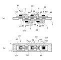
本発明に係る固体酸化物形燃料電池の実施形態について図面を参照しつつ説明する。図1は、本実施形態に係る固体酸化物形燃料電池の正面断面図(a)であり、図2は図1の固体酸化物形燃料電池の平面図(b)である。 An embodiment of a solid oxide fuel cell according to the present invention will be described with reference to the drawings. FIG. 1 is a front sectional view (a) of the solid oxide fuel cell according to the present embodiment, and FIG. 2 is a plan view (b) of the solid oxide fuel cell of FIG.
図1に示すように、この固体酸化物形燃料電池は、いわゆる単室型の燃料電池であり、複数の貫通孔11が形成された支持基板1上に、5個の単セル2が配置され、これらがインターコネクタ3で直列に接続されている。ここでは、支持基板1の上面から貫通孔11を塞ぐ単セルを第1,第2,及び第3単セル21〜23と称し、支持基板1の下面から貫通孔11を塞ぐ単セルを第4,第5単セルと称することとする。
As shown in FIG. 1, this solid oxide fuel cell is a so-called single-chamber fuel cell, and five
支持基板1は、緻密な金属基板で形成されており、この基板1には、所定間隔をおいて矩形状の貫通孔11が5個形成されている。そして、この支持基板1によって支持される各単セル21〜25は、薄膜状の電解質を51〜55、空気極41〜45及び燃料極61〜65で挟むことにより形成されている。まず、第1〜第3単セル21〜23について説明する。これらの単セル21〜25は、支持基板1の上面から貫通孔11を塞ぐ矩形状の電解質51〜53を有している。そして、各電解質51〜53の上面には、矩形状の燃料極61〜63が配置されている。また、各貫通孔11の下側から露出する電解質51〜53の下面には、空気極41〜43が配置されている。すなわち、各空気極41〜43は、貫通孔11内に配置されている。
The
次に、第4及び第5単セル24,25について説明する。これらの単セル24,25は、支持基板1の下面から貫通孔11を塞ぐ矩形状の電解質54,55を有している。そして、貫通孔11の上側から露出する各電解質54,55の上面には、矩形状の空気極44,45が配置されている。つまり、各空気極44,45は、貫通孔11内に配置されている。また、各電解質54,55の下面には、燃料極64,65が配置されている。
Next, the fourth and fifth
各インターコネクタ3は、支持基板1の上面及び下面にそれぞれ配線され、隣接する単セル同士を接続している。例えば、支持基板1の上面では、第1単セル21の燃料極61と、第4単セル24の空気極44とがインターコネクタ3によって接続されている。同様に、第2及び第5単セル22,25もインターコネクタ3によって接続されている。また、支持基板1の下面では、第4単セル24の空気極44と第2単セル22の燃料極62とがインターコネクタ3によって接続されているほか、第5及び第3単セル25,23もインターコネクタ3によって接続されている。
Each
続いて、上記燃料電池を構成する材料について説明する。支持基板1は、緻密な材料で構成されており、金属及び金属酸化物からなる材料で構成されていれば良い。例えば、金属材料としては、Fe,Ti,Cr,Cu,Ni,Agを用いることができ、1種を単独で使用してもよいし、2種以上が合金化されていてもよい。例えば、ステンレス系耐熱材料などが使用でき、具体的には、オーステナイト系ステンレス鋼、フェライト系ステンレス鋼を用いることができる。また、本実施形態では、絶縁性の支持基板1を用いているが、上記のような金属基板を絶縁性にするには、例えば、空気中で加熱することで表面を酸化させるという方法がある。その他、真空成膜法やゾルゲル法等により、金属表面にアルミナ等の絶縁性の被膜をコ−ティングにより形成することができる。なお、この支持基板1の厚さは、50〜5000μmであることが好ましい。
Subsequently, materials constituting the fuel cell will be described. The
電解質51〜55の材料としては、固体酸化物形燃料電池の電解質として公知のものを使用することができ、例えば、サマリウムやガドリニウム等をドープしたセリア系酸化物(GDC)、ストロンチウムやマグネシウムをドープしたランタン・ガレード系酸化物、スカンジウムやイットリウムを含むジルコニア系酸化物(YSZ)などの酸素イオン伝導性セラミックス材料を用いることができる。
As the materials of the
燃料極61〜65及び空気極41〜45は、セラミックス粉末材料により形成することができる。このとき用いられる粉末の平均粒径は、好ましくは10nm〜100μmであり、さらに好ましくは50nm〜50μmであり、特に好ましくは100nm〜10μmである。なお、平均粒径は、例えば、JISZ8901にしたがって計測することができる。
The
燃料極61〜65は、例えば、金属触媒と酸化物イオン導電体からなるセラミックス粉末材料との混合物を用いることができる。このとき用いられる金属触媒としては、ニッケル、鉄、コバルトや、貴金属(白金、ルテニウム、パラジウム等)等の還元性雰囲気中で安定で、水素酸化活性を有する材料を用いることができる。また、酸化物イオン導電体としては、蛍石型構造又はペロブスカイト型構造を有するものを好ましく用いることができる。蛍石型構造を有するものとしては、例えばサマリウムやガドリニウム等をドープしたセリア系酸化物、スカンジウムやイットリウムを含むジルコニア系酸化物などを挙げることができる。また、ペロブスカイト型構造を有するものとしてはストロンチウムやマグネシウムをドープしたランタン・ガレード系酸化物を挙げることができる。上記材料の中では、酸化物イオン導電体とニッケルとの混合物で、燃料極を形成することが好ましい。なお、酸化物イオン導電体からなるセラミックス材料とニッケルとの混合形態は、物理的な混合形態であってもよいし、ニッケルへの粉末修飾またはセラミックス材料へのニッケル修飾などの形態であってもよい。また、上述したセラミックス材料は、1種類を単独で、或いは2種類以上を混合して使用することができる。また、燃料極61〜65は、金属触媒を単体で用いて構成することもできる。
As the
空気極41〜45を形成するセラミックス粉末材料としては、例えば、ペロブスカイト型構造等を有するCo,Fe,Ni,Cr又はMn等からなる金属酸化物を用いることができる。具体的には(Sm,Sr)CoO3,(La,Sr)MnO3,(La,Sr)CoO3,(La,Sr)(Fe,Co)O3,(La,Sr)(Fe,Co,Ni)O3などの酸化物が挙げられ、好ましくは、(La,Sr)(Fe,Co)O3である。上述したセラミックス材料は、1種を単独で、或いは2種以上を混合して使用することができる。
As the ceramic powder material forming the
インターコネクタ3は、Pt,Au,Ag,Ni,Cu,ステンレス系材料等の導電性金属材料,又はLa(Cr,Mg)O3,(La,Ca)CrO3,(La,Sr)CrO3などのランタン・クロマイト系等の導電性金属酸化物材料によって形成することができ、これらのうちの1種を単独で使用してもよいし、2種以上を混合して使用してもよい。
The
上記電解質51〜55、燃料極61〜65、空気極41〜45、及びインターコネクタ3は、例えば、ウエットコ−ティング法或いは、ドライコーティング法によって形成することができる。ウエットコ−ティング法としては、スクリーン印刷法、電気泳動(EPD)法、ドクターブレード法、スプレーコート法、インクジェット法、スピンコ−ト法、ディップコート法等が例示できる。その際、これら電解質、燃料極、空気極、及びインターコネクタは、ペースト状にする必要があり、上述した材料を主成分として、さらにバインダー樹脂、有機溶媒などが適量加えられることにより形成される。より詳細には、上記主成分とバインダー樹脂との混合において、上記主成分が50〜95重量%となるように、バインダー樹脂等を加えることが好ましい。また、ドライコーティング法としては、例えば蒸着法、スパッタリング法、イオンプレーティング法、化学気相成長(CVD)法、電気化学気相成長法、イオンビーム法、レーザーアブレーション法、大気圧プラズマ成膜法、減圧プラズマ成膜法等で形成することもできる。電解質51〜55の膜厚は、5〜500μmとなるように形成するが、10〜100μmであることがさらに好ましい。また、燃料極61〜65、及び空気極41〜45の膜厚は、5〜100μmとなるように形成するが、5〜50μmであることがさらに好ましい。
The
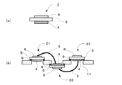
次に上記のように構成された固体酸化物形燃料電池の製造方法について図面を参照しつつ説明する。図2及び図3は、本実施形態に係る固体酸化物形燃料電池の製造方法を示す説明図である。 Next, a method for manufacturing the solid oxide fuel cell configured as described above will be described with reference to the drawings. 2 and 3 are explanatory views showing a method of manufacturing the solid oxide fuel cell according to the present embodiment.
まず、絶縁性の支持基板1を準備し(図2(a))、その上面及び下面に複数の電解質51〜55を所定間隔をおいて形成する(図2(b))。このとき、各電解質51〜55は、支持基板1を挟んで千鳥状にずれるように配置される。すなわち、一部のみが重なるのはよいが、大部分で重ならないようにする。この例では、支持基板1の上面の第1から第3単セルの電解質51〜53が所定間隔をおいて配置され、支持基板1の下面の第4及び第5単セルの電解質54,55が、支持基板1の上面の電解質51〜53の間に配置されるようにする。その作製においては、所定の形状、間隔で電解質ペーストを塗布した後、これを所定時間、乾燥・焼結して緻密な電解質51〜55を形成する。或いは、板状の電解質を貼り付けることもできる。
First, an insulating
次に、エッチングにより貫通孔を形成する。まず、支持基板1の上面から下面側の電解質54,55が露出するように2個の貫通孔11を形成する。続いて、支持基板1の下面から上面側の電解質51〜53が露出するように3個の貫通孔11を形成する。これに続いて、支持基板1の上面側の電解質51〜53の上面に燃料極ペーストを塗布し、所定時間、乾燥・焼結することで、燃料極61〜63を形成する。同様に、支持基板1の下面側の電解質54,55の下面にも燃料極ペーストを塗布し、所定時間、乾燥・焼結することで、燃料極64,65を形成する(図3(a))。次に、上面側に開口する貫通孔11内に空気極を形成する。すなわち、貫通孔11を介して上面側に露出する電解質54,55の上面に、空気極ペーストを塗布し、所定時間、乾燥・焼結して空気極44,45を形成する。同様に、貫通孔11を介して下面側に露出する電解質51〜53の下面に、空気極ペーストを塗布し、所定時間、乾燥・焼結して空気極41〜43を形成する。こうして、5つの単セル21〜25が完成する。
Next, a through hole is formed by etching. First, the two through
続いて、支持基板1の上面の2箇所にインターコネクタ3を形成する。まず、第1単セル21の燃料極61と第4単セル24の空気極44とを接続する。この空気極44は、貫通孔11から露出しているものである。同様に、第2単セル22の燃料極62と第5単セル25の空気極45を接続する。これに続いて、支持基板1の下面の2箇所においてもインターコネクタ3を形成する。つまり、第4単セル24の燃料極64と第2単セル22の空気極42とを接続する。同様に、第5単セル25の燃料極65と第3単セル23の空気極43を接続する。いずれのインターコネクタ3も、インターコネクタ用ペーストを塗布した後、所定時間、乾燥・焼結することで形成する(図2(c))。以上の工程により、図1に示す固体酸化物形燃料電池が完成する。
Subsequently, the
上記のように構成された燃料電池は、次のように発電が行われる。まず、支持基板1の上面側及び下面側に燃料ガスと、酸化剤ガスの混合ガスを供給する。燃料ガスは、水素、又はメタン、エタンなどの炭化水素で構成され、酸化剤ガスは、空気などで構成される。こうして、燃料極61〜65及び空気極41〜45がそれぞれ燃料ガス及び酸化剤ガスと選択的に接触するため、燃料極61〜65と空気極41〜45との間で、電解質51〜55を介した酸素イオン伝導が起こり、発電が行われる。
The fuel cell configured as described above generates power as follows. First, a mixed gas of fuel gas and oxidant gas is supplied to the upper surface side and the lower surface side of the
以上のように、上記実施形態によれば、緻密な支持基板1を用いているので、電池の機械的強度を向上することができる。また、支持基板1に複数の貫通孔11を形成し、支持基板1の上面または下面側から貫通孔11を塞ぐように、単セル21〜25をそれぞれ配置している。こうして、緻密な支持基板上に複数の単セルを形成して高出力化を図っている。このとき、各電極は、支持基板1の上面側及び下面側のいずれにおいても露出するようになっているので、構造の簡易な単室型の電池として用いることができる。
As described above, according to the embodiment, since the
以上、本発明の実施形態について説明したが、本発明はこれらに限定されるものではなく、本発明の趣旨を逸脱しない限りにおいて種々の変更が可能である。例えば、上記実施形態では、絶縁性の支持基板1を用いたが、導電性の基板を用い、製造工程において、この基板に絶縁膜をコーティングして絶縁することもできる。以下、この工程について図4を参照しつつ説明する。
As mentioned above, although embodiment of this invention was described, this invention is not limited to these, A various change is possible unless it deviates from the meaning of this invention. For example, in the above-described embodiment, the insulating
導電性の金属基板を用いる場合であっても、図2(a)〜図2(c)までは、上記実施形態と同様である。続いて、図4(a)に示すように、貫通孔11を形成した後、各貫通孔11の内壁面、及びその周縁の電解質51〜55と接触する位置までを、アルミナなどの絶縁層7でコーティングする。この後の工程は、図3と同様であり、燃料極61〜65(図4(b))、空気極41〜45(図4(c))、及びインターコネクタ3をそれぞれ形成すれば(図4(d))、燃料電池が完成する。但し、インターコネクタ3を形成する際には、短絡を防止するため、支持基板1において絶縁膜7がコーティングされていない部分に、ペーストが塗布されないようにする。この例においては、導電性の金属基板を用いても、後の工程で絶縁膜7によるコーティングを行えば、絶縁性の支持基板1として用いることができる。
Even when a conductive metal substrate is used, FIGS. 2A to 2C are the same as those in the above embodiment. Subsequently, as shown in FIG. 4A, after the through
また、上記実施形態では、貫通孔11の中に空気極41〜45を形成しているが、燃料極61〜65を配置することもできる。すなわち、燃料極と空気極の位置を入れ替えてもよい。
Moreover, in the said embodiment, although the air electrodes 41-45 are formed in the through-
さらに、図5に示すような方法で本発明に係る固体酸化物形燃料電池を形成することもできる。まず、図5(a)に示すように、絶縁性又は導電性の基板1を準備する。続いて、図5(b)に示すように、この基板1に上述したのと同様の貫通孔11をエッチングにより複数個形成する。その後、導電性基板を用いている場合には、絶縁処理を行う。すなわち、焼結により基板表面を酸化したり、絶縁性の被膜をコーティングする。続いて、図5(c)に示すような、燃料極6を基板とする燃料極支持型の単セル2を複数個準備する。この単セルの材料及び製造方法は、上述したとおりである。このとき、電解質5及び燃料極6は同じ平面形状であるが、空気極4は、それよりも小さく且つ貫通孔11よりも小さく形成しておく。
Furthermore, the solid oxide fuel cell according to the present invention can be formed by the method shown in FIG. First, as shown in FIG. 5A, an insulating or
そして、図5(d)に示すように、各単セル21〜23を貫通孔11を塞ぐように、基板1の上面側及び下面側から配置する。同図においては、両端のセル21,23が、基板1の上面から貫通孔11(第1の貫通孔)を塞ぎ、中央の単セル22が基板1の下面から貫通孔(第2の貫通孔)11を塞いでいる。両端の単セル21,23においては、空気極4が貫通孔11を介して基板1の下面から露出するように配置する。一方、中央の単セル22においては、空気極4が貫通孔11を介して基板1の上面から露出するように配置する。このとき、いずれの単セル21〜23においても、電解質5の周縁を貫通孔11の周縁に溶着材9によって接着する。このような溶着材9としては、例えば、銀や、金、白金、銅及びこれら金属を含む化合物等を用いることができる。これに続いて、図5(e)に示すように、隣接する単セルを、ワイヤ状のインターコネクタ3によって接続する。インターコネクタ3は、貫通孔11に収容されていない燃料極6と、貫通孔11に収容されている空気極4とを接続する。つまり、例えば、左端の単セル21の燃料極6と、中央の単セル22の空気極4とをインターコネクタ3によって接続する。インターコネクタ3は、貫通孔11を介して、空気極4に接続される。インターコネクタ3と各電極4,6とは、例えば、スポット溶接や接着固定用のセラミックスペーストにより接続される。このような、製造方法であっても、上述したのと同様の効果を得ることができる。
And as shown in FIG.5 (d), each single cell 21-23 is arrange | positioned from the upper surface side and the lower surface side of the board |
なお、この方法では、インターコネクタとしては、ワイヤ以外に、メッシュ、ペーストの印刷など種々のものを使用することができる。また、この方法で用いる単セルは、上記のように、燃料極支持型ではなく、電解質基板を用いる電解質支持型でもよい。すなわち、図6(a)に示すように、電解質支持型の単セル2を準備する。この単セル2は、電解質基板5の両面に燃料極6、及び空気極4がそれぞれ形成されたものであり、空気極4が貫通孔11よりも小さくなっている。そして、図6(b)に示すように、溶着材9によって、電解質5と貫通孔11の周縁とを接着することで、単セル2を基板1に固定する。空気極4が貫通孔11に嵌め込まれるのは、図5と同じである。この構成によっても、上記と同様の効果を得ることができる。
In this method, as the interconnector, various types such as mesh and paste printing can be used in addition to the wire. Further, the single cell used in this method may be an electrolyte support type using an electrolyte substrate instead of the fuel electrode support type as described above. That is, as shown in FIG. 6A, an electrolyte-supporting
1 支持基板
11 貫通孔
21〜23 第1〜第3単セル(第1グループの単セル)
24,25 第4、第5単セル(第2グループの単セル)
3 インターコネクタ
41〜45 空気極
51〜55 電解質
61〜65 燃料極
7 絶縁膜
DESCRIPTION OF
24, 25 Fourth and fifth single cells (second group of single cells)
3
Claims (5)
前記各第1の貫通孔を塞ぐようにそれぞれ配置され、電解質を燃料極及び空気極で挟むことで構成された少なくとも1つの第1及び第2グループの単セルと、
前記支持基板の一方面又は他方面の少なくとも一方に配置され、前記複数の単セルを接続する少なくとも一つのインターコネクタと、を備え、
前記第1グループの単セルは、前記電解質が前記支持基板の一方面側から前記貫通孔を塞ぐように配置され、当該電解質の一方面に一方の電極が形成され、前記貫通孔を介して露出する電解質の他方面に他方の電極が形成されており、
前記第2グループの単セルは、前記電解質が前記支持基板の他方面側から前記貫通孔を塞ぐように配置され、当該電解質の他方面に一方の電極が形成され、前記貫通孔を介して露出する電解質の一方面に一方の電極が形成されており、
前記支持基板の一方面に配置されるインターコネクタは、前記第1グループの単セルの一方の電極と、第2グループの単セルの他方の電極を接続し、
前記支持基板の他方面に配置されるインターコネクタは、前記第1グループの単セルの他方の電極と、第2グループの単セルの一方の電極を接続する、固体酸化物形燃料電池。 A dense support substrate having a plurality of through-holes having at least an insulating surface;
Each of the first and second groups of single cells, each of which is arranged so as to close each of the first through holes, and is configured by sandwiching an electrolyte between the fuel electrode and the air electrode;
At least one interconnector that is disposed on at least one of the one surface or the other surface of the support substrate and connects the plurality of single cells; and
The single cells of the first group are arranged so that the electrolyte closes the through hole from one surface side of the support substrate, and one electrode is formed on one surface of the electrolyte, and is exposed through the through hole. The other electrode is formed on the other surface of the electrolyte,
The unit cells of the second group are arranged so that the electrolyte closes the through hole from the other surface side of the support substrate, and one electrode is formed on the other surface of the electrolyte, and is exposed through the through hole. One electrode is formed on one side of the electrolyte
The interconnector disposed on one surface of the support substrate connects one electrode of the first group of single cells and the other electrode of the second group of single cells,
The interconnector disposed on the other surface of the support substrate is a solid oxide fuel cell that connects the other electrode of the first group of single cells and one electrode of the second group of single cells.
前記支持基板の他方面から一方面側の電解質が露出するように貫通孔を形成するステップと、
前記支持基板の一方面から他方面側の電解質が露出するように貫通孔を形成するステップと、
前記各電解質において前記各貫通孔とは反対側の面に、燃料極及び空気極のいずれか一方の電極を形成するステップと、
前記各電解質において前記各貫通孔を介して露出する面に、他方の電極を形成するステップと、
前記支持基板の一方面において、前記電解質上にある一方の電極と前記貫通孔から露出する他方の電極とを接続するようにインターコネクタを形成するステップと、
前記支持基板の他方面において、前記電解質上にある一方の電極と前記貫通孔から露出する他方の電極とを接続するようにインターコネクタを形成するステップと、
を備えている、固体酸化物形燃料電池の製造方法。 Forming at least one electrolyte on each of one side and the other side of the dense insulating support substrate so as not to completely overlap the support substrate;
Forming a through-hole so that the electrolyte on one side is exposed from the other side of the support substrate;
Forming a through hole so that the electrolyte on the other surface side is exposed from one surface of the support substrate;
Forming one of a fuel electrode and an air electrode on a surface of each electrolyte opposite to each through hole;
Forming the other electrode on the surface exposed through each through-hole in each electrolyte; and
Forming an interconnector on one side of the support substrate to connect one electrode on the electrolyte and the other electrode exposed from the through hole;
Forming an interconnector on the other surface of the support substrate so as to connect one electrode on the electrolyte and the other electrode exposed from the through hole;
A method for producing a solid oxide fuel cell.
前記支持基板の他方面から一方面側の電解質が露出するように貫通孔を形成するステップと、
前記支持基板の一方面から他方面側の電解質が露出するように貫通孔を形成するステップと、
前記各貫通孔の内壁面及びその近傍に前記電解質と接触するように、絶縁膜を形成するステップと、
前記各電解質において前記各貫通孔とは反対側の面に、燃料極及び空気極のいずれか一方の電極を形成するステップと、
前記各電解質において前記各貫通孔を介して露出する面に、他方の電極を形成するステップと、
前記支持基板の一方面において、前記絶縁膜が形成されていない部分を避けつつ、前記電解質上にある一方の電極と前記貫通孔から露出する他方の電極とを接続するようにインターコネクタを形成するステップと、
前記支持基板の他方面において、前記絶縁膜が形成されていない部分を避けつつ、前記電解質上にある一方の電極と前記貫通孔から露出する他方の電極とを接続するようにインターコネクタを形成するステップと、
を備えている、固体酸化物形燃料電池の製造方法。 Forming at least one electrolyte on each of one side and the other side of the dense insulating support substrate so as not to completely overlap the support substrate;
Forming a through-hole so that the electrolyte on one side is exposed from the other side of the support substrate;
Forming a through hole so that the electrolyte on the other surface side is exposed from one surface of the support substrate;
Forming an insulating film in contact with the electrolyte on the inner wall surface of each through-hole and in the vicinity thereof;
Forming one of a fuel electrode and an air electrode on a surface of each electrolyte opposite to each through hole;
Forming the other electrode on the surface exposed through each through-hole in each electrolyte; and
An interconnector is formed on one surface of the support substrate so as to connect one electrode on the electrolyte and the other electrode exposed from the through hole while avoiding a portion where the insulating film is not formed. Steps,
An interconnector is formed on the other surface of the support substrate so as to connect one electrode on the electrolyte and the other electrode exposed from the through hole while avoiding a portion where the insulating film is not formed. Steps,
A method for producing a solid oxide fuel cell.
少なくとも表面が絶縁性を有する緻密な支持基板に複数の第1及び第2の貫通孔を形成するステップと、
前記各第1の貫通孔の周縁に前記電解質を接着することで、当該第1の貫通孔を前記支持基板の一方面から前記電解質で塞ぎ、前記空気極が前記支持基板の他方面へ露出するように前記単セルを配置するステップと、
前記各第2の貫通孔の周縁に前記電解質を接着することで、当該第2の貫通孔を前記支持基板の他方面から前記電解質で塞ぎ、前記空気極が前記支持基板の一方面へ露出するように前記単セルを配置するステップと、
前記第1の貫通孔に配置された単セルの燃料極と、前記第2の貫通孔から露出する前記空気極とをインターコネクタによって接続するステップと、
前記第2の貫通孔に配置された単セルの燃料極と、前記第1の貫通孔から露出する前記空気極とをインターコネクタによって接続するステップと、
を備えている、固体酸化物形燃料電池の製造方法。
Preparing a plurality of single cells formed by sandwiching an electrolyte between a fuel electrode and an air electrode;
Forming a plurality of first and second through holes in a dense support substrate having at least an insulating surface; and
By adhering the electrolyte to the periphery of each first through hole, the first through hole is closed with the electrolyte from one surface of the support substrate, and the air electrode is exposed to the other surface of the support substrate. Arranging the single cells as follows:
By adhering the electrolyte to the periphery of each second through-hole, the second through-hole is closed with the electrolyte from the other surface of the support substrate, and the air electrode is exposed to one surface of the support substrate. Arranging the single cells as follows:
Connecting a single-cell fuel electrode disposed in the first through hole and the air electrode exposed from the second through hole by an interconnector;
Connecting a single-cell fuel electrode disposed in the second through-hole and the air electrode exposed from the first through-hole by an interconnector;
A method for producing a solid oxide fuel cell.
Priority Applications (1)
| Application Number | Priority Date | Filing Date | Title |
|---|---|---|---|
| JP2008088737A JP5217567B2 (en) | 2008-03-28 | 2008-03-28 | Solid oxide fuel cell and method for producing the same |
Applications Claiming Priority (1)
| Application Number | Priority Date | Filing Date | Title |
|---|---|---|---|
| JP2008088737A JP5217567B2 (en) | 2008-03-28 | 2008-03-28 | Solid oxide fuel cell and method for producing the same |
Publications (2)
| Publication Number | Publication Date |
|---|---|
| JP2009245663A true JP2009245663A (en) | 2009-10-22 |
| JP5217567B2 JP5217567B2 (en) | 2013-06-19 |
Family
ID=41307341
Family Applications (1)
| Application Number | Title | Priority Date | Filing Date |
|---|---|---|---|
| JP2008088737A Expired - Fee Related JP5217567B2 (en) | 2008-03-28 | 2008-03-28 | Solid oxide fuel cell and method for producing the same |
Country Status (1)
| Country | Link |
|---|---|
| JP (1) | JP5217567B2 (en) |
Cited By (2)
| Publication number | Priority date | Publication date | Assignee | Title |
|---|---|---|---|---|
| JP2013093181A (en) * | 2011-10-25 | 2013-05-16 | Ngk Insulators Ltd | Fuel cell structure |
| EP3613874A4 (en) * | 2017-04-10 | 2020-12-09 | Mitsui Mining & Smelting Co., Ltd. | Solid-electrolyte integrated element, method for manufacturing solid-electrolyte integrated element, and solid-electrolyte element |
Citations (5)
| Publication number | Priority date | Publication date | Assignee | Title |
|---|---|---|---|---|
| JP2002280015A (en) * | 2001-03-21 | 2002-09-27 | National Institute Of Advanced Industrial & Technology | Single room type solid electrolyte fuel cell and its manufacturing method |
| JP2003051319A (en) * | 2001-08-06 | 2003-02-21 | Nissan Motor Co Ltd | Cell plate for solid electrolyte type fuel cell and power generation unit |
| JP2005322452A (en) * | 2004-05-07 | 2005-11-17 | Nissan Motor Co Ltd | Cell plate for solid oxide fuel cell, and solid oxide fuel cell |
| JP2006221884A (en) * | 2005-02-08 | 2006-08-24 | Dainippon Printing Co Ltd | Single chamber type solid oxide fuel cell |
| JP2007103092A (en) * | 2005-09-30 | 2007-04-19 | Dainippon Printing Co Ltd | Solid oxide fuel cell |
-
2008
- 2008-03-28 JP JP2008088737A patent/JP5217567B2/en not_active Expired - Fee Related
Patent Citations (5)
| Publication number | Priority date | Publication date | Assignee | Title |
|---|---|---|---|---|
| JP2002280015A (en) * | 2001-03-21 | 2002-09-27 | National Institute Of Advanced Industrial & Technology | Single room type solid electrolyte fuel cell and its manufacturing method |
| JP2003051319A (en) * | 2001-08-06 | 2003-02-21 | Nissan Motor Co Ltd | Cell plate for solid electrolyte type fuel cell and power generation unit |
| JP2005322452A (en) * | 2004-05-07 | 2005-11-17 | Nissan Motor Co Ltd | Cell plate for solid oxide fuel cell, and solid oxide fuel cell |
| JP2006221884A (en) * | 2005-02-08 | 2006-08-24 | Dainippon Printing Co Ltd | Single chamber type solid oxide fuel cell |
| JP2007103092A (en) * | 2005-09-30 | 2007-04-19 | Dainippon Printing Co Ltd | Solid oxide fuel cell |
Cited By (3)
| Publication number | Priority date | Publication date | Assignee | Title |
|---|---|---|---|---|
| JP2013093181A (en) * | 2011-10-25 | 2013-05-16 | Ngk Insulators Ltd | Fuel cell structure |
| EP3613874A4 (en) * | 2017-04-10 | 2020-12-09 | Mitsui Mining & Smelting Co., Ltd. | Solid-electrolyte integrated element, method for manufacturing solid-electrolyte integrated element, and solid-electrolyte element |
| US11569528B2 (en) | 2017-04-10 | 2023-01-31 | Mitsui Mining & Smelting Co., Ltd. | Solid electrolyte integrated device, method of manufacturing solid electrolyte integrated device, and solid electrolyte element |
Also Published As
| Publication number | Publication date |
|---|---|
| JP5217567B2 (en) | 2013-06-19 |
Similar Documents
| Publication | Publication Date | Title |
|---|---|---|
| JP5135853B2 (en) | Solid oxide fuel cell | |
| JP5422867B2 (en) | Solid oxide fuel cell and method for producing the same | |
| JP2016066504A (en) | Current collector for fuel electrode and solid oxide fuel cell | |
| JP5369471B2 (en) | Solid oxide fuel cell and method for producing the same | |
| JP5217567B2 (en) | Solid oxide fuel cell and method for producing the same | |
| JP2013033617A (en) | Solid oxide fuel cell and manufacturing method of solid oxide fuel cell | |
| JP2006019044A (en) | Solid oxide fuel cell | |
| JP2009245654A (en) | Manufacturing method for solid oxide fuel cell, and the solid oxide fuel cell | |
| JP5233143B2 (en) | Solid oxide fuel cell | |
| JP5315656B2 (en) | Stack structure of solid oxide fuel cell | |
| JP5114999B2 (en) | Solid oxide fuel cell and stack structure thereof | |
| JP5245205B2 (en) | Solid oxide fuel cell | |
| JP5320947B2 (en) | Solid oxide fuel cell and method for producing the same | |
| JP5045024B2 (en) | Single-chamber solid oxide fuel cell and method for producing the same | |
| JP5211531B2 (en) | Solid oxide fuel cell | |
| JP5233148B2 (en) | Solid oxide fuel cell | |
| JP2008047380A (en) | Single chamber type solid oxide fuel cell | |
| JP2008277236A (en) | Solid oxide fuel cell, and its stack structure | |
| JP2005251611A (en) | Cell for solid oxide fuel cell and solid oxide fuel cell | |
| JP2008077887A (en) | Single-chamber solid oxide fuel cell and stack structure thereof | |
| JP5445551B2 (en) | Solid oxide fuel cell | |
| JP2008053016A (en) | Single chamber type solid oxide fuel cell, and its stack structure | |
| JP5316153B2 (en) | Single-chamber solid oxide fuel cell | |
| JP5124992B2 (en) | Method for manufacturing stack structure of solid oxide fuel cell | |
| JP5181600B2 (en) | Solid oxide fuel cell, stack structure of solid oxide fuel cell, and manufacturing method of solid oxide fuel cell |
Legal Events
| Date | Code | Title | Description |
|---|---|---|---|
| A621 | Written request for application examination |
Free format text: JAPANESE INTERMEDIATE CODE: A621 Effective date: 20110119 |
|
| A977 | Report on retrieval |
Free format text: JAPANESE INTERMEDIATE CODE: A971007 Effective date: 20130123 |
|
| TRDD | Decision of grant or rejection written | ||
| A01 | Written decision to grant a patent or to grant a registration (utility model) |
Free format text: JAPANESE INTERMEDIATE CODE: A01 Effective date: 20130205 |
|
| A61 | First payment of annual fees (during grant procedure) |
Free format text: JAPANESE INTERMEDIATE CODE: A61 Effective date: 20130218 |
|
| FPAY | Renewal fee payment (event date is renewal date of database) |
Free format text: PAYMENT UNTIL: 20160315 Year of fee payment: 3 |
|
| R150 | Certificate of patent or registration of utility model |
Free format text: JAPANESE INTERMEDIATE CODE: R150 |
|
| LAPS | Cancellation because of no payment of annual fees |