JP2009244227A - Light wave interference measuring method - Google Patents
Light wave interference measuring method Download PDFInfo
- Publication number
- JP2009244227A JP2009244227A JP2008094042A JP2008094042A JP2009244227A JP 2009244227 A JP2009244227 A JP 2009244227A JP 2008094042 A JP2008094042 A JP 2008094042A JP 2008094042 A JP2008094042 A JP 2008094042A JP 2009244227 A JP2009244227 A JP 2009244227A
- Authority
- JP
- Japan
- Prior art keywords
- light
- light beam
- shape
- subject
- spherical
- Prior art date
- Legal status (The legal status is an assumption and is not a legal conclusion. Google has not performed a legal analysis and makes no representation as to the accuracy of the status listed.)
- Abandoned
Links
Images
Abstract
Description
本発明は、特に、非球面レンズの非球面形状を測定するために用いられる光波干渉測定装置に関する。 The present invention particularly relates to an optical interference measuring apparatus used for measuring the aspherical shape of an aspherical lens.
近年、非球面光学素子の非球面表面形状を高精度に測定したいという要求が、特にレンズ設計、製造等の分野において強い。 In recent years, there is a strong demand for measuring the aspheric surface shape of an aspherical optical element with high accuracy, particularly in the fields of lens design and manufacturing.
非球面形状の高精度な測定手法に係る技術としては、フィゾー型タイプの干渉計において、被測定非球面の基準とされた参照非球面を有する参照用反射素子を、該被測定非球面と近接配置し、該参照用反射素子で反射して被測定非球面に戻る参照光と、該被測定非球面において反射される物体光との光干渉により得られる干渉縞に基づき、被測定非球面の形状を測定し、この測定時において干渉縞をスキャニングする、いわゆる干渉縞スキャン法が知られている(下記特許文献1参照)。 As a technique related to a highly accurate measurement method of an aspherical shape, in a Fizeau type interferometer, a reference reflecting element having a reference aspherical surface as a standard for the measured aspherical surface is placed close to the measured aspherical surface. The measured aspheric surface is arranged on the basis of interference fringes obtained by optical interference between the reference light reflected by the reference reflecting element and returning to the measured aspheric surface and the object light reflected on the measured aspheric surface. A so-called interference fringe scanning method is known in which the shape is measured and the interference fringes are scanned during the measurement (see Patent Document 1 below).
さらに、非球面形状の高精度な測定手法に係る技術としては、下記特許文献2、3等に開示されたようないわゆる点スキャン法や、下記特許文献4等に記載されたような開口合成法を利用する手法が知られている。 Furthermore, as a technique related to a highly accurate measurement method of an aspherical shape, a so-called point scan method as disclosed in Patent Documents 2 and 3 below, and an aperture synthesis method as described in Patent Document 4 below and the like. A method of using is known.
しかしながら、上記特許文献、特に上記特許文献1等に記載された手法では、参照非球面(非球面基準面)と被測定非球面との各光軸のズレが測定に大きく影響すること等の理由から、非球面形状をなす被検面の全領域について同時に、良好な干渉縞を得ることができない。結局、被検面全体について干渉縞情報を得るためには、各領域について干渉縞情報が現れる毎に撮像を繰返し、これら撮像された多数の干渉縞情報を組み合わせる等の処理が必要であるから、干渉縞情報の取得操作が極めて繁雑となる。 However, in the method described in the above-mentioned patent documents, particularly in the above-mentioned patent document 1, etc., the reason that the deviation of each optical axis between the reference aspheric surface (aspheric reference surface) and the measured aspheric surface greatly affects the measurement. Therefore, good interference fringes cannot be obtained simultaneously for the entire region of the test surface having an aspherical shape. Eventually, in order to obtain interference fringe information for the entire test surface, it is necessary to repeat imaging every time interference fringe information appears for each region, and to perform processing such as combining a number of these captured interference fringe information. The operation of acquiring interference fringe information becomes extremely complicated.
したがって、上記各特許文献に記載された手法では、いずれも膨大な測定時間を要することになる。 Therefore, all of the methods described in the above patent documents require enormous measurement time.
さらに、上記特許文献1記載のものでは、装置の製造コストが高価になってしまい、また、上記特許文献4記載のものでは、装置構成が複雑になるという問題もある。 Further, the device described in Patent Document 1 has a high manufacturing cost of the device, and the device described in Patent Document 4 has a problem that the device configuration is complicated.
本発明は、このような事情に鑑みなされたものであり、非球面光学素子の表面形状を簡易かつ低コストで短時間のうちに測定し得る光波干渉測定装置を提供することを目的とするものである。 The present invention has been made in view of such circumstances, and an object of the present invention is to provide an optical interference measuring apparatus capable of measuring the surface shape of an aspherical optical element easily and at low cost in a short time. It is.
本発明に係る光波干渉測定装置は、
光源からの光束を光束分離合成手段により二分して、一方を被検体方向に向かう第1光束とするとともに、他方を参照体方向に向かう第2光束とし、
前記光束分離合成手段によって、該第1光束の該被検体からの戻り光と該第2光束の該参照体からの戻り光とを合成して干渉光となし、所定位置に配された撮像体上に前記被検体の表面形状情報に基づく干渉縞像を形成する光波干渉測定装置において、
前記被検体が表面形状を測定すべき非球面光学素子であり、前記参照体が該被検体の基準とすべき形状をなす非球面光学素子であり、
前記光束分離合成手段と前記被検体との間には、前記光束分離合成手段からの前記第1光束を前記被検体の表面に入射させるとともに、該被検体の表面から反射された該第1光束を前記光束分離合成手段に戻すように構成され、該被検体に対向する面を第1基準球面とされた第1球面基準レンズが配され、
前記光束分離合成手段と前記参照体との間には、前記光束分離合成手段からの前記第2光束を前記参照体の表面に入射させるとともに、該参照体の表面から反射された該第2光束を前記光束分離合成手段に戻すように構成され、該参照体に対向する面を、前記第1基準球面と同一曲率の第2基準球面を有する第2球面基準レンズが配され、
前記光束分離合成手段と前記第1球面基準レンズとの間の前記第1光束の光路上、および前記光束分離合成手段と前記第2球面基準レンズとの間の前記第2光束の光路上の少なくとも一方に、入射した該第1光束または該第2光束の波面形状を補正して出射せしめるデフォーマブルミラーを配設してなることを特徴とするものである。
The optical interference measuring apparatus according to the present invention is
The light beam from the light source is divided into two by the light beam separating / synthesizing means, and one is used as the first light beam directed toward the subject, and the other as the second light beam directed toward the reference body.
An imaging body arranged at a predetermined position by combining the return light of the first light flux from the subject and the return light of the second light flux from the reference body to form interference light by the light beam separating and combining means. In the light wave interference measurement apparatus for forming an interference fringe image based on the surface shape information of the subject on the top,
The subject is an aspherical optical element whose surface shape is to be measured, and the reference body is an aspherical optical element having a shape to be a standard of the subject;
The first light beam from the light beam separation / synthesis unit is incident on the surface of the subject and the first light beam reflected from the surface of the subject is interposed between the light beam separation / synthesis unit and the subject. And a first spherical reference lens having a surface facing the subject as a first reference spherical surface,
Between the light beam separation / synthesis unit and the reference body, the second light beam from the light beam separation / synthesis unit is incident on the surface of the reference body and the second light beam reflected from the surface of the reference body And a second spherical reference lens having a second reference spherical surface having the same curvature as the first reference spherical surface on the surface facing the reference body.
At least on the optical path of the first luminous flux between the luminous flux separating / combining means and the first spherical reference lens, and on the optical path of the second luminous flux between the luminous flux separating / combining means and the second spherical reference lens. On the other hand, a deformable mirror for correcting the wavefront shape of the incident first light beam or the second light beam and emitting it is provided.
この場合において、前記撮像体により得られた、前記被検体の表面形状情報に基づく干渉縞像の縞密度が低くなるように、前記入射した第1光束または第2光束の波面形状を補正するよう、前記デフォーマブルミラーの表面形状を変形駆動するコントローラを備えてなることが好ましい。 In this case, the wavefront shape of the incident first light beam or second light beam is corrected so that the fringe density of the interference fringe image obtained by the imaging body based on the surface shape information of the subject is lowered. It is preferable that a controller for deforming and driving the surface shape of the deformable mirror is provided.
また、上記光波干渉測定装置は、等光路長型のマイケルソンタイプとすることが好ましい。 Moreover, it is preferable that the light wave interference measuring apparatus is an equal optical path length Michelson type.
また、この場合において、前記第1光束と前記第2光束を光反射と光透過により分離し、かつ合成する前記光束分離合成手段の分離面が、前記ビームスプリッタの一面に設けられ、
前記ビームスプリッタが断面楔形状をなす板状に構成されていることが好ましい。
In this case, a separation surface of the light beam separation / combination means for separating and combining the first light beam and the second light beam by light reflection and light transmission is provided on one surface of the beam splitter,
It is preferable that the beam splitter has a plate shape having a wedge shape in cross section.
また、該ビームスプリッタの前記一面側に射出される光束の光路中であって、この光路中に配されたいずれかの前記球面基準レンズと該ビームスプリッタとの間に、前記第1光束と前記第2光束の光路長の差を補償する補償板が配されていることが好ましい。 Further, in the optical path of the light beam emitted to the one surface side of the beam splitter, the first light beam and the beam splitter between any of the spherical reference lenses arranged in the optical path and the beam splitter It is preferable that a compensation plate for compensating for the difference in optical path length of the second light beam is provided.
なお、前記基準球面は、上記参照体表面形状を表す非球面のベースとなる球面とされている。すなわち、該非球面を周知の非球面式で表した場合における曲率C(または曲率半径R)の値を、その曲率(または曲率半径)とした球面とされる。 The reference spherical surface is a spherical surface serving as an aspherical base representing the reference body surface shape. That is, the spherical surface having the curvature (or radius of curvature) as the value of curvature C (or radius of curvature R) when the aspheric surface is expressed by a well-known aspherical expression is used.
本発明に係る光波干渉測定装置は、光源からの光束を光束分離合成手段により二分して、一方を被検体方向に向かう第1光束とするとともに、他方を参照体方向に向かう第2光束としており、また、被検体から反射された第1光束と参照体から反射された第2光束とを該光束分離合成手段により合成することにより、その被検体表面形状情報を干渉縞情報として得ることができるようにしている。 In the light wave interference measuring apparatus according to the present invention, the light beam from the light source is divided into two by the light beam separation / combination means, and one is used as the first light beam directed toward the subject and the other as the second light beam directed toward the reference body. Moreover, the subject surface shape information can be obtained as interference fringe information by combining the first light beam reflected from the subject and the second light beam reflected from the reference body by the light beam separation and synthesis means. I am doing so.
そして、光束分離合成手段により合成せしめられる干渉光は、被検体表面での第1光束の反射光と、この被検体表面形状の基準となる参照体表面での第2光束の反射光との差に基づくものであるが、上記第1光束の反射光は被検体表面と第1基準球面との形状差に基づく情報(以下、形状差情報と称する)を有しており、一方、上記第2光束の反射光は参照体表面と第2基準球面との形状差情報を有しているから、両反射光束の干渉により形成された干渉縞は、基本的には上記2つの形状差情報に基づくものとなる。 The interference light combined by the light beam separation / combination means is the difference between the reflected light of the first light beam on the surface of the subject and the reflected light of the second light beam on the surface of the reference body that is the reference for the shape of the subject surface. However, the reflected light of the first luminous flux has information based on the shape difference between the subject surface and the first reference spherical surface (hereinafter referred to as shape difference information), while the second light is reflected on the second light beam. Since the reflected light of the light beam has shape difference information between the surface of the reference body and the second reference spherical surface, the interference fringes formed by the interference of both reflected light beams are basically based on the above two shape difference information. It will be a thing.
通常の非球面形状であれば、上記構成によっても縞密度を十分に小さいものとすることが可能であり、良好な光波干渉測定を行うことが可能である。このような構成は、既に本願発明者によって発明され、特願2007-340136号(平成19年12月28日出願)において、既に特許庁に開示されている。 If it is a normal aspherical shape, the fringe density can be made sufficiently small even with the above-described configuration, and good optical interference measurement can be performed. Such a configuration has already been invented by the present inventor and has already been disclosed to the Patent Office in Japanese Patent Application No. 2007-340136 (filed on Dec. 28, 2007).
しかしながら、被検体の非球面形状によっては、局部的に球面形状との差が大きくなる場合があり、このような場合には、その問題となる部分の縞密度が大きくなってしまうことがある。 However, depending on the aspherical shape of the subject, the difference from the spherical shape may be locally increased. In such a case, the fringe density in the problematic part may be increased.
そこで、本発明に係る光波干渉測定装置においては、前記光束分離合成手段と前記第1球面基準レンズとの間の前記第1光束の光路上、および前記光束分離合成手段と前記第2球面基準レンズとの間の前記第2光束の光路上の少なくとも一方に、入射した該第1光束または該第2光束の波面形状を補正して出射せしめるデフォーマブルミラーを配設している。一般に、デフォーマブルミラーは可動範囲が小さいので、それのみによって、被検面の非球面形状からの光束波面に対応する程度まで、参照光の光束波面を変形させることは難しい。しかし、本発明のものでは、上述したように、2つの基準球面によって、第1段階の調整はなされているので、第1段階の調整によっても、なお局部的に縞密度が大きくなる部分について、デフォーマブルミラーで光束波面を補正すればよいので、いわば微調整とすることができ、これにより、局部的に球面形状との差が大きくなる非球面形状に対しても縞密度を十分に小さいものとすることが可能であり、種々のタイプの非球面形状の被検体に対して汎用的に適用することで良好な光波干渉測定を行うことが可能である。 Therefore, in the light wave interference measuring apparatus according to the present invention, the light beam separation / combination means and the second spherical reference lens on the optical path of the first light flux between the light flux separation / combination means and the first spherical reference lens. A deformable mirror that corrects the wavefront shape of the incident first light beam or the second light beam and emits it is disposed at least on the optical path of the second light beam. In general, since the deformable mirror has a small movable range, it is difficult to deform the light flux wavefront of the reference light only to that extent to correspond to the light flux wavefront from the aspherical shape of the test surface. However, in the present invention, as described above, the first stage of adjustment is performed by the two reference spherical surfaces. Therefore, even with the first stage of adjustment, the portion where the fringe density is locally increased is as follows. Since it is only necessary to correct the wavefront of the light beam with a deformable mirror, it can be finely adjusted, so that the fringe density is sufficiently small even for an aspherical shape where the difference from the spherical shape increases locally. It is possible to perform good optical interference measurement by applying it to various types of aspherical objects for general purposes.
したがって、本発明に係る光波干渉測定装置によれば、非球面光学素子の表面形状を簡易かつ低コストで短時間のうちに測定することが可能となる。 Therefore, according to the light wave interference measuring apparatus according to the present invention, the surface shape of the aspherical optical element can be measured easily and at low cost in a short time.
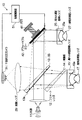
以下、本発明の実施形態について図面を用いて説明する。図1は本発明の実施形態に係る光波干渉測定装置の構成を概略的に示す図である。 Hereinafter, embodiments of the present invention will be described with reference to the drawings. FIG. 1 is a diagram schematically showing a configuration of a lightwave interference measuring apparatus according to an embodiment of the present invention.
図1に示すように、この装置10は、光源11と、光源11からの光束を平行光束とするコリメートレンズ12と、このコリメートレンズ12からの平行光束を透過/反射分離面13aにより二分するビームスプリッタ13と、この透過/反射分離面13aにより反射された第1の平行光束を、被検非球面レンズ17上に照射するとともに、被検非球面レンズ17からの反射光を透過/反射分離面13aに戻す高NA球面基準レンズ(第1球面基準レンズ)15と、この透過/反射分離面13aを透過した第2の平行光束を、参照非球面レンズ27上に照射するとともに、参照非球面レンズ27からの反射光を透過/反射分離面13aに戻す高NA球面基準レンズ(第2球面基準レンズ)25と、透過/反射分離面13aにおける被検非球面レンズ17からの反射光と参照非球面レンズ27からの反射光との干渉により生じる干渉縞を撮像する干渉計CCDカメラ31と、合波された上記両反射光による干渉縞を干渉計CCDカメラ31の撮像面上に結像させる結像レンズ29を備えている。
As shown in FIG. 1, the
また、この装置10は、入射した第2の平行光束(ビームスプリッタ13方向から入射した第2の平行光束および高NA球面基準レンズ25方向から入射した第2の平行光束)の波面形状を補正して反射するデフォーマブルミラー42を、ビームスプリッタ13と高NA球面基準レンズ25との間に備えている。
In addition, the
また、このデフォーマブルミラー42にはピエゾ素子41が付設されており、周知の位相シフト法を採用することが可能となっている。
In addition, a
さらに、この装置10は、コンピュータなどからなる制御演算部51を備えている。この制御演算部51は、撮像された干渉縞情報が入力され、その干渉縞情報に基づき、被検非球面レンズ17の非球面表面形状を演算、解析するものであるが、その一方、その干渉縞情報に基づき、縞密度が高い部分に対して、その縞密度を低下させるように第2の平行光束の波面形状を補正すべく、デフォーマブルミラー42の表面形状を変形させる駆動信号を出力するものである。
Further, the
なお、デフォーマブルミラー42とは、反射型の光変調装置であって、上記駆動信号に応じて空間的な光の位相分布を変更させるように構成されたものである。すなわち、多数のミラーデバイスの位置や傾きが印加電圧によって各々変動可能に構成されており、多数のミラーデバイスによって形成される曲面も変形可能とされている。このようなデフォーマブルミラー42に対して、上記駆動信号を入力させることにより、入射した第2の平行光束の波面形状を微小量だけ変形させることができる。このようにすることにより、局部的に球面形状との差が大きくなる非球面形状に対しても縞密度を十分に小さいものとすることが可能である。また、参照非球面レンズ27を極めて高精度に加工せずとも、参照非球面レンズ27からの波面を理想的な形状に補正することができる。 The deformable mirror 42 is a reflection-type light modulation device, and is configured to change the spatial light phase distribution according to the drive signal. That is, the positions and inclinations of a large number of mirror devices can be varied according to the applied voltage, and the curved surface formed by the large number of mirror devices can also be deformed. By inputting the drive signal to the deformable mirror 42, the wavefront shape of the incident second parallel light beam can be changed by a minute amount. By doing so, it is possible to make the fringe density sufficiently small even for an aspherical shape in which the difference from the spherical shape locally increases. Further, the wavefront from the reference aspheric lens 27 can be corrected to an ideal shape without processing the reference aspheric lens 27 with extremely high accuracy.
なお、図1中には、デフォーマブルミラー42により補正された波面が模式的に描かれている。 In FIG. 1, the wavefront corrected by the deformable mirror 42 is schematically drawn.
また、装置10において、上記ビームスプリッタ13は、透過/反射分離面13aとは反対側の面からの反射光によりノイズ干渉縞が発生するのを防止するため、対向する両面が互いに非平行となるように楔形状に構成されている。
Further, in the
また、光束がビームスプリッタ13中を通過する回数が、第1の平行光束によるものでは1回であるのに対し、第2の平行光束によるものでは3回となっており、互いの光路長を一致させるために補償板14が設けられ、かつビームスプリッタ13と同一の楔方向となるように配された略同一の楔形状体にて構成されている。
In addition, the number of times the light beam passes through the
また、高NA球面基準レンズ(第1球面基準レンズ)15と高NA球面基準レンズ(第2球面基準レンズ)25は主要部のみを模式的に描いたものであって、各凹面は基準球面15a、25aとされ、互いに同一曲率に形成されている。
Further, the high NA spherical reference lens (first spherical reference lens) 15 and the high NA spherical reference lens (second spherical reference lens) 25 schematically depict only main parts, and each concave surface has a reference
以下、本発明の実施形態装置の作用について説明する。
一般に、被検非球面レンズ17は、形状の基準となる参照非球面レンズ27に対して、若干の形状誤差を有しているものであり、この光波干渉測定装置10は、このような被検非球面レンズ17の形状誤差を、参照非球面レンズ27の表面形状に基づき、定量的に測定するものである。
Hereinafter, the operation of the embodiment device of the present invention will be described.
In general, the test aspheric lens 17 has a slight shape error with respect to the reference aspheric lens 27 serving as a shape standard. The shape error of the aspheric lens 17 is quantitatively measured based on the surface shape of the reference aspheric lens 27.
すなわち、上記透過/反射分離面13aにおいて二分された光原11からの光束のうち、被検非球面レンズ17に向かった第1の光束は、被検非球面レンズ17と高NA球面基準レンズ15の第1基準球面15aとの表面形状差に応じた波面情報を担持した状態で透過/反射分離面13aに戻る。これに対して、上記透過/反射分離面13aにおいて二分された光束のうち、参照非球面レンズ27に向かった第2の光束は、参照非球面レンズ27と高NA球面基準レンズ25の第2基準球面25aとの表面形状差に応じた波面情報をデフォーマブルミラー42により補正したものを担持した状態で透過/反射分離面13aに戻る。透過/反射分離面13aに戻った2つの光束は、この透過/反射分離面13aにおいて合波され、参照非球面レンズ27に対する被検非球面レンズ17の相対形状誤差情報が干渉縞情報とされて干渉計CCDカメラ31の撮像面上に形成される。
That is, the first light beam directed to the aspheric lens 17 to be tested out of the light beams from the light source 11 divided into two at the transmission /
ただし、上述したように、参照非球面レンズ27で反射された第2の光束は、参照非球面レンズ27と第2基準球面25aとの表面形状差に基づく波面情報とデフォーマブルミラー42により付与された波面情報とを加算したものを担持しているから、上述した干渉縞情報を演算する際には、実際に得られた干渉縞情報からデフォーマブルミラー42により付与された波面情報を差し引いた上で、被検体の形状情報を解析することが肝要である。
これにより、縞密度が高い部分についても大幅に低下させることができることから、種々のタイプの非球面形状に対し、全有効領域の形状を同時に、かつ良好に取得することが可能となる。
However, as described above, the second light flux reflected by the reference aspheric lens 27 is given by the wavefront information based on the surface shape difference between the reference aspheric lens 27 and the second reference
As a result, even a portion having a high fringe density can be significantly reduced, and therefore, the shapes of all effective regions can be simultaneously and satisfactorily acquired for various types of aspheric shapes.
したがって、被検体の各領域の干渉縞情報を部分的に求めた後、互いに組み合わせる必要があった、従来の非球面光学素子の干渉縞形状測定に比べて、測定解析時間を大幅に軽減することが可能である。また、解析ソフトも簡易なものとすることができ、測定に要するコストを低減することができる。 Therefore, the measurement analysis time can be greatly reduced compared to the conventional interference fringe shape measurement of aspherical optical elements, which must be combined with each other after partially obtaining the interference fringe information of each region of the subject. Is possible. Also, the analysis software can be simplified, and the cost required for measurement can be reduced.
また、本実施形態装置は、等光路長型を構築し得る、マイケルソンタイプに構成されており、また、補償板14を用いビームスプリッタ13中の光束通過に応じて生じた光路長の差を補償しているので、光源11からの出力光を低可干渉光とすることができる。これによって光路中の他の光学面からの反射光に基づくノイズ干渉縞の発生を回避することができる。
In addition, the apparatus according to the present embodiment is configured as a Michelson type capable of constructing an equal optical path length type, and the difference in optical path length generated according to the passage of the light beam in the
なお、補償板14はビームスプリッタ13と同様の硝材によって形成されており、屈折率および分散値は同一とされている。また、形状も同様に形成されている。ただし、補償板14の屈折率、分散値および形状は、必ずしもビームスプリッタ13のものと一致していなくともよく、要は、光路中にビームスプリッタ13を挿入したことにより生じた上記両光路の光路長の差を補償しうるものであればよい。
The compensation plate 14 is formed of the same glass material as that of the
以上、本発明の実施形態について説明したが、本発明はかかる実施形態に限られるものではなく、種々に態様を変更することができる。 As mentioned above, although embodiment of this invention was described, this invention is not limited to this embodiment, A mode can be variously changed.
例えば、上記実施形態のものでは、ビームスプリッタ13と高NA球面基準レンズ25との間に、デフォーマブルミラー42を設けているが、これに替え、またはこれに加えて、ビームスプリッタ13と高NA球面基準レンズ15との間に、同様のデフォーマブルミラーを設けるようにしても、上記実施形態のものと同様の作用効果を得ることができる。
For example, in the above embodiment, the deformable mirror 42 is provided between the
また、上記実施形態においては、被検体が、局部的に球面形状との差が大きくなる非球面形状を有しており、その部分に対して縞密度を小さくするために被検体からの波面を補正する際にデフォーマブルミラーを用いる場合について記載しているが、本発明装置におけるデフォーマブルミラーによる波面の補正はこれに限られるものではない。例えば、参照非球面レンズ27が高精度に加工されていない場合等において、参照非球面レンズ27からの波面を、デフォーマブルミラーによって理想的な形状に補正するようにしてもよく、この場合には、参照非球面レンズの製造コストを安価にすることができる。 Further, in the above embodiment, the subject has an aspherical shape in which the difference from the spherical shape locally increases, and the wavefront from the subject is reduced in order to reduce the fringe density for that portion. Although the case where a deformable mirror is used for correction is described, the correction of the wavefront by the deformable mirror in the device of the present invention is not limited to this. For example, when the reference aspherical lens 27 is not processed with high accuracy, the wavefront from the reference aspherical lens 27 may be corrected to an ideal shape by a deformable mirror. The manufacturing cost of the reference aspheric lens can be reduced.
また、上記実施形態のものは、低可干渉光束を用いて測定を行うようにしており、これにより高精度な測定結果を得ることが可能となるものであるが、高可干渉光束を用いて測定を行うようにしてもよい。この場合には、光学系の2つの光路の光路長を互いに高精度に一致させる必要がなくなり、光学系調整の簡易化を図ることが可能となる。 In the above-described embodiment, measurement is performed using a low coherent light beam, and thereby a highly accurate measurement result can be obtained. Measurement may be performed. In this case, it is not necessary to match the optical path lengths of the two optical paths of the optical system with high accuracy, and it becomes possible to simplify the adjustment of the optical system.
また、被検体としては、上記非球面レンズに限られるものではなく、球面レンズの測定に用いることができることは勿論であり、例えば反射ミラー等のレンズ以外の光学素子の表面形状(球面、非球面、自由曲面等)についても適用可能である。 Further, the subject is not limited to the above-mentioned aspherical lens, and can naturally be used for measurement of a spherical lens. For example, the surface shape (spherical surface, aspherical surface) of an optical element other than a lens such as a reflecting mirror is used. , Free-form surface, etc.).
10 光波干渉測定装置
11 光源
12 コリメータレンズ
13 ビームスプリッタ
13a 透過/反射分離面
14 補償板
15 高NA球面基準レンズ(第1球面基準レンズ)
15a、25a 基準球面
17 被検非球面レンズ
25 高NA球面基準レンズ(第2球面基準レンズ)
27 参照非球面レンズ
29 結像レンズ
31 干渉計CCDカメラ
41 ピエゾ素子
42 デフォーマブルミラー
51 制御演算部
DESCRIPTION OF
15a, 25a Reference spherical surface 17 Tested aspheric lens 25 High NA spherical reference lens (second spherical reference lens)
27 Reference Aspherical Lens 29 Imaging Lens 31
Claims (5)
前記光束分離合成手段によって、該第1光束の該被検体からの戻り光と該第2光束の該参照体からの戻り光とを合成して干渉光となし、所定位置に配された撮像体上に前記被検体の表面形状情報に基づく干渉縞像を形成する光波干渉測定装置において、
前記被検体が表面形状を測定すべき非球面光学素子であり、前記参照体が該被検体の基準とすべき形状をなす非球面光学素子であり、
前記光束分離合成手段と前記被検体との間には、前記光束分離合成手段からの前記第1光束を前記被検体の表面に入射させるとともに、該被検体の表面から反射された該第1光束を前記光束分離合成手段に戻すように構成され、該被検体に対向する面を第1基準球面とされた第1球面基準レンズが配され、
前記光束分離合成手段と前記参照体との間には、前記光束分離合成手段からの前記第2光束を前記参照体の表面に入射させるとともに、該参照体の表面から反射された該第2光束を前記光束分離合成手段に戻すように構成され、該参照体に対向する面を、前記第1基準球面と同一曲率の第2基準球面を有する第2球面基準レンズが配され、
前記光束分離合成手段と前記第1球面基準レンズとの間の前記第1光束の光路上、および前記光束分離合成手段と前記第2球面基準レンズとの間の前記第2光束の光路上の少なくとも一方に、入射した該第1光束または該第2光束の波面形状を補正して出射せしめるデフォーマブルミラーを配設してなることを特徴とする光波干渉測定装置。 The light beam from the light source is divided into two by the light beam separating / synthesizing means, and one is used as the first light beam directed toward the subject, and the other as the second light beam directed toward the reference body.
An imaging body arranged at a predetermined position by combining the return light of the first light flux from the subject and the return light of the second light flux from the reference body to form interference light by the light beam separating and combining means. In the light wave interference measurement apparatus for forming an interference fringe image based on the surface shape information of the subject on the top,
The subject is an aspherical optical element whose surface shape is to be measured, and the reference body is an aspherical optical element having a shape to be a standard of the subject;
The first light beam from the light beam separation / synthesis unit is incident on the surface of the subject and the first light beam reflected from the surface of the subject is interposed between the light beam separation / synthesis unit and the subject. And a first spherical reference lens having a surface facing the subject as a first reference spherical surface,
Between the light beam separation / synthesis unit and the reference body, the second light beam from the light beam separation / synthesis unit is incident on the surface of the reference body and the second light beam reflected from the surface of the reference body And a second spherical reference lens having a second reference spherical surface having the same curvature as the first reference spherical surface on the surface facing the reference body.
At least on the optical path of the first luminous flux between the luminous flux separating / combining means and the first spherical reference lens, and on the optical path of the second luminous flux between the luminous flux separating / combining means and the second spherical reference lens. On the other hand, a deformable mirror for correcting and emitting the wavefront shape of the incident first light flux or the second light flux is provided.
前記ビームスプリッタが断面楔形状をなす板状に構成されていることを特徴とする請求項1〜3のうちいずれか1項記載の光波干渉測定装置。 A separation surface of the light beam separation / combination means for separating and combining the first light flux and the second light flux by light reflection and light transmission is provided on one surface of the beam splitter,
4. The light wave interference measuring apparatus according to claim 1, wherein the beam splitter is configured in a plate shape having a wedge shape in cross section.
An optical path of the light beam emitted to the one surface side of the beam splitter, and the optical path of the first light beam and the second light beam between the spherical reference lens disposed in the optical path and the beam splitter. 5. The optical interference measuring apparatus according to claim 4, further comprising a compensating plate for compensating for the difference in length.
Priority Applications (1)
| Application Number | Priority Date | Filing Date | Title |
|---|---|---|---|
| JP2008094042A JP2009244227A (en) | 2008-03-31 | 2008-03-31 | Light wave interference measuring method |
Applications Claiming Priority (1)
| Application Number | Priority Date | Filing Date | Title |
|---|---|---|---|
| JP2008094042A JP2009244227A (en) | 2008-03-31 | 2008-03-31 | Light wave interference measuring method |
Publications (1)
| Publication Number | Publication Date |
|---|---|
| JP2009244227A true JP2009244227A (en) | 2009-10-22 |
Family
ID=41306270
Family Applications (1)
| Application Number | Title | Priority Date | Filing Date |
|---|---|---|---|
| JP2008094042A Abandoned JP2009244227A (en) | 2008-03-31 | 2008-03-31 | Light wave interference measuring method |
Country Status (1)
| Country | Link |
|---|---|
| JP (1) | JP2009244227A (en) |
Cited By (4)
| Publication number | Priority date | Publication date | Assignee | Title |
|---|---|---|---|---|
| CN108827595A (en) * | 2018-03-12 | 2018-11-16 | 西安应用光学研究所 | Detection device based on adaptation theory optical system mismachining tolerance |
| CN109781032A (en) * | 2019-02-28 | 2019-05-21 | 西安交通大学 | Based on the optical freeform optics surface face shape interferometric measuring means of cascade adaptive and measurement method |
| CN111795804A (en) * | 2020-06-24 | 2020-10-20 | 湖北航天技术研究院总体设计所 | Online testing method and system for high-energy laser reflection optical element |
| RU2803879C1 (en) * | 2023-04-03 | 2023-09-21 | Акционерное общество "Лыткаринский завод оптического стекла" | Method for measuring the shape of off-axis asspherical optical part |
Citations (13)
| Publication number | Priority date | Publication date | Assignee | Title |
|---|---|---|---|---|
| JPS61140802A (en) * | 1984-12-14 | 1986-06-27 | Hitachi Ltd | Light wave interference device preventing reverse surface reflected light |
| US4725144A (en) * | 1986-02-25 | 1988-02-16 | R & D Associates | Optic element testing method and apparatus |
| JPS644702A (en) * | 1987-06-29 | 1989-01-09 | Hitachi Ltd | Mirror curvature varying device |
| JPH0425705A (en) * | 1990-05-22 | 1992-01-29 | Nec Corp | Optical interferometer |
| JPH06313707A (en) * | 1993-04-29 | 1994-11-08 | Olympus Optical Co Ltd | Shape measuring method and apparatus |
| JPH08193805A (en) * | 1995-01-13 | 1996-07-30 | Fuji Xerox Co Ltd | Interferometer and method for using it |
| JPH1194515A (en) * | 1997-09-16 | 1999-04-09 | Fuji Photo Optical Co Ltd | Light wave interferometer |
| JP2001349704A (en) * | 2000-06-12 | 2001-12-21 | Fuji Photo Optical Co Ltd | Interferometer device |
| JP2003035508A (en) * | 2001-07-24 | 2003-02-07 | Mitsutoyo Corp | Image measurement head and image measuring device |
| JP2005083954A (en) * | 2003-09-10 | 2005-03-31 | Fujinon Corp | Tomographic image system |
| JP2006064669A (en) * | 2004-08-30 | 2006-03-09 | Fujinon Corp | Interferometer device for measuring virtual contact surface |
| JP2006126103A (en) * | 2004-11-01 | 2006-05-18 | Canon Inc | Aspheric surface shape measuring method |
| JP2006242853A (en) * | 2005-03-04 | 2006-09-14 | Sony Corp | Interference device and measuring technique of planar shape |
-
2008
- 2008-03-31 JP JP2008094042A patent/JP2009244227A/en not_active Abandoned
Patent Citations (13)
| Publication number | Priority date | Publication date | Assignee | Title |
|---|---|---|---|---|
| JPS61140802A (en) * | 1984-12-14 | 1986-06-27 | Hitachi Ltd | Light wave interference device preventing reverse surface reflected light |
| US4725144A (en) * | 1986-02-25 | 1988-02-16 | R & D Associates | Optic element testing method and apparatus |
| JPS644702A (en) * | 1987-06-29 | 1989-01-09 | Hitachi Ltd | Mirror curvature varying device |
| JPH0425705A (en) * | 1990-05-22 | 1992-01-29 | Nec Corp | Optical interferometer |
| JPH06313707A (en) * | 1993-04-29 | 1994-11-08 | Olympus Optical Co Ltd | Shape measuring method and apparatus |
| JPH08193805A (en) * | 1995-01-13 | 1996-07-30 | Fuji Xerox Co Ltd | Interferometer and method for using it |
| JPH1194515A (en) * | 1997-09-16 | 1999-04-09 | Fuji Photo Optical Co Ltd | Light wave interferometer |
| JP2001349704A (en) * | 2000-06-12 | 2001-12-21 | Fuji Photo Optical Co Ltd | Interferometer device |
| JP2003035508A (en) * | 2001-07-24 | 2003-02-07 | Mitsutoyo Corp | Image measurement head and image measuring device |
| JP2005083954A (en) * | 2003-09-10 | 2005-03-31 | Fujinon Corp | Tomographic image system |
| JP2006064669A (en) * | 2004-08-30 | 2006-03-09 | Fujinon Corp | Interferometer device for measuring virtual contact surface |
| JP2006126103A (en) * | 2004-11-01 | 2006-05-18 | Canon Inc | Aspheric surface shape measuring method |
| JP2006242853A (en) * | 2005-03-04 | 2006-09-14 | Sony Corp | Interference device and measuring technique of planar shape |
Cited By (4)
| Publication number | Priority date | Publication date | Assignee | Title |
|---|---|---|---|---|
| CN108827595A (en) * | 2018-03-12 | 2018-11-16 | 西安应用光学研究所 | Detection device based on adaptation theory optical system mismachining tolerance |
| CN109781032A (en) * | 2019-02-28 | 2019-05-21 | 西安交通大学 | Based on the optical freeform optics surface face shape interferometric measuring means of cascade adaptive and measurement method |
| CN111795804A (en) * | 2020-06-24 | 2020-10-20 | 湖北航天技术研究院总体设计所 | Online testing method and system for high-energy laser reflection optical element |
| RU2803879C1 (en) * | 2023-04-03 | 2023-09-21 | Акционерное общество "Лыткаринский завод оптического стекла" | Method for measuring the shape of off-axis asspherical optical part |
Similar Documents
| Publication | Publication Date | Title |
|---|---|---|
| US11672631B2 (en) | Intraoral scanner calibration | |
| US5898501A (en) | Apparatus and methods for measuring wavefront aberrations of a microlithography projection lens | |
| US6992779B2 (en) | Interferometer apparatus for both low and high coherence measurement and method thereof | |
| JP2009162539A (en) | Light wave interferometer apparatus | |
| JP5394317B2 (en) | Rotationally symmetric aspherical shape measuring device | |
| JP5954979B2 (en) | Measuring device with multi-wavelength interferometer | |
| US8411280B2 (en) | Surface shape measurement apparatus | |
| JP4963231B2 (en) | Reconfigurable interferometer system | |
| WO2013084557A1 (en) | Shape-measuring device | |
| EP2306142A1 (en) | Surface shape measurement apparatus | |
| JP2010133860A (en) | Shape calculation method | |
| JP4667965B2 (en) | Light beam measuring device | |
| JP2009244227A (en) | Light wave interference measuring method | |
| JP2007298281A (en) | Measuring method and device of surface shape of specimen | |
| JP2005201703A (en) | Interference measuring method and system | |
| JP4810693B2 (en) | Lightwave interference measurement device | |
| JP2014074620A (en) | Measuring device and measuring method | |
| JP2006284233A (en) | Apparatus for measuring system error and interferometer system for wavefront measurement equipped with the same | |
| JP4145670B2 (en) | Adjustment method of branch imaging mechanism in phase shift interference fringe simultaneous imaging device | |
| JPH1038758A (en) | Method and equipment for measuring wave aberration of lens for i-line | |
| JP2009186436A (en) | Light wave interference measuring apparatus | |
| JPH10221030A (en) | Aspherical shape measuring device | |
| JPH0420844A (en) | Optical-phase-difference measuring apparatus | |
| JP2014206505A (en) | Measuring device using interferometer | |
| JP2000088548A (en) | Interferometer and method of measuring surface shape |
Legal Events
| Date | Code | Title | Description |
|---|---|---|---|
| A621 | Written request for application examination |
Free format text: JAPANESE INTERMEDIATE CODE: A621 Effective date: 20100609 |
|
| A711 | Notification of change in applicant |
Free format text: JAPANESE INTERMEDIATE CODE: A711 Effective date: 20100621 |
|
| A977 | Report on retrieval |
Free format text: JAPANESE INTERMEDIATE CODE: A971007 Effective date: 20110422 |
|
| A131 | Notification of reasons for refusal |
Effective date: 20110427 Free format text: JAPANESE INTERMEDIATE CODE: A131 |
|
| A762 | Written abandonment of application |
Free format text: JAPANESE INTERMEDIATE CODE: A762 Effective date: 20110624 |