JP2009243545A - Method for restricting growth of crack in piping - Google Patents
Method for restricting growth of crack in piping Download PDFInfo
- Publication number
- JP2009243545A JP2009243545A JP2008089149A JP2008089149A JP2009243545A JP 2009243545 A JP2009243545 A JP 2009243545A JP 2008089149 A JP2008089149 A JP 2008089149A JP 2008089149 A JP2008089149 A JP 2008089149A JP 2009243545 A JP2009243545 A JP 2009243545A
- Authority
- JP
- Japan
- Prior art keywords
- crack
- pipe
- ice
- piping
- water
- Prior art date
- Legal status (The legal status is an assumption and is not a legal conclusion. Google has not performed a legal analysis and makes no representation as to the accuracy of the status listed.)
- Granted
Links
Images


Landscapes
- Pipe Accessories (AREA)
Abstract
Description
本発明は、応力腐食割れや疲労によりき裂が生じたオーステナイト系ステンレス鋼などの配管のき裂進展抑止方法に関する。 The present invention relates to a crack growth inhibiting method for piping such as austenitic stainless steel in which a crack is generated due to stress corrosion cracking or fatigue.
配管を拡管させて残留応力を緩和する方法は、特許文献1に記載されている。
A method for relaxing the residual stress by expanding the pipe is described in
この記載された応力緩和方法では、内部に水を保有した配管の上流および下流に水密な栓を形成し、この水密な栓に挟まれた配管内部の水を冷却して凝固させ、氷を形成して体積膨張させることが試みられている。 In this stress relaxation method, water-tight plugs are formed upstream and downstream of a pipe holding water inside, and water inside the pipe sandwiched between the water-tight plugs is cooled and solidified to form ice. Attempts have been made to expand the volume.
また、内径の大きな配管への施工では、氷栓の形成位置を配管突合せ溶接部の上流および下流の曲げ管またはエルボまたは分岐部とする。 Further, in the construction of a pipe having a large inner diameter, the ice plug is formed at the bent pipe, elbow, or branch part upstream and downstream of the pipe butt weld.
この結果、配管内の水密な栓で挟まれた水の圧力が上昇することで配管が拡管され塑性変形する。これにより配管の残留応力が改善する。 As a result, the pipe is expanded and plastically deformed by increasing the pressure of the water sandwiched between the watertight plugs in the pipe. This improves the residual stress of the piping.
氷栓の形成後に配管内の氷栓で挟まれた水の圧力を上昇させる場合、配管の内径が大きくなるに従い、氷栓に加わる管軸方向の推進力は大きくなる。 When the pressure of the water sandwiched between the ice plugs in the pipe is increased after the ice plug is formed, the propulsive force in the tube axis direction applied to the ice plug increases as the inner diameter of the pipe increases.
そのため、従来の技術では、配管の内径が大きい配管に対して施工する場合、エルボ部または分岐管に氷栓を形成することにより、氷栓に作用する管軸方向の荷重を管壁により支持させるため、施工する箇所が制限される。 Therefore, in the conventional technology, when the pipe is constructed with a large inner diameter of the pipe, an ice plug is formed on the elbow part or the branch pipe to support the load in the tube axis direction acting on the ice plug by the pipe wall. For this reason, the construction site is limited.
また、配管の内径が大きくなるに従い、完全に凍結せずに配管内面に一定厚さの氷層が形成された状態で温度が均衡し、配管中央部まで完全に凍結しない可能性がある。 Further, as the inner diameter of the pipe increases, the temperature is balanced in a state where an ice layer of a certain thickness is formed on the inner surface of the pipe without being completely frozen, and there is a possibility that the pipe does not completely freeze up to the center of the pipe.
そこで、本発明は、内面に貫通しないき裂を有する直径の大きい配管に対して、き裂の進展抑止のために、管軸方向の推進力に耐え、配管内面のき裂近傍に圧力を加えることが可能な氷栓を確実に形成する配管のき裂進展抑止方法を提供することを目的とする。 Therefore, the present invention withstands the propulsive force in the tube axis direction and applies pressure to the vicinity of the crack on the inner surface of the pipe in order to prevent the crack from progressing for a pipe having a large diameter having a crack that does not penetrate the inner surface. It is an object of the present invention to provide a method for preventing crack propagation in a pipe, which can reliably form an ice plug.
本発明の配管のき裂進展抑止方法は、内面に貫通しない微小なき裂を有する鉛直方向の配管のき裂進展抑止方法であって、配管の内部を気体環境中とし、き裂の鉛直下部を氷点下に冷却し、配管の内面の管壁に沿って鉛直上部より水を供給して氷栓を形成し、き裂の鉛直上部まで水が溜め、き裂の鉛直上部を氷点下に冷却し、き裂が形成されている位置に溜められた水を氷点下に冷却することを特徴とする。 The method for inhibiting crack propagation in a pipe according to the present invention is a method for inhibiting crack propagation in a vertical pipe having a minute crack that does not penetrate the inner surface. Cool below the freezing point, supply water from the vertical upper part along the pipe wall on the inner surface of the pipe to form an ice plug, collect water up to the vertical upper part of the crack, cool the vertical upper part of the crack below the freezing point, and It is characterized in that the water stored at the position where the crack is formed is cooled below freezing point.
ここで、鉛直下部とは、配管の鉛直方向であって、き裂の位置より下部の位置のことであり、鉛直上部とは、配管の鉛直方向であって、き裂の位置より上部の位置のことである。 Here, the vertical lower part is the vertical direction of the pipe and is a position below the crack position, and the vertical upper part is the vertical direction of the pipe and the position above the crack position. That is.
そして、き裂が形成されている位置は、配管の外部から、直接、冷却せず、き裂の鉛直上部および鉛直下部の配管の外部から冷却し、その冷却熱によって、き裂が形成されている位置を氷点下に冷却することを特徴とする。 And the position where the crack is formed is not cooled directly from the outside of the pipe, it is cooled from the outside of the vertical upper and lower pipes, and the crack is formed by the cooling heat. The position is cooled below freezing point.
なお、き裂が形成されている位置近傍の配管の外部には断熱材を形成し、断熱材の鉛直下部および鉛直上部を冷却することで、き裂が形成されている位置を冷却し、氷を作る。 In addition, a heat insulating material is formed outside the pipe in the vicinity of the position where the crack is formed, and the vertical lower part and the vertical upper part of the heat insulating material are cooled, thereby cooling the position where the crack is formed and make.
つまり、き裂の鉛直下部および鉛直上部に形成された氷栓(氷)により、き裂が形成されている位置近傍に溜められた水が、氷栓で閉じられる。こうした氷栓で閉じられた領域を形成した後に、この領域に、配管の内部の管壁に沿って、先に形成された氷栓の冷却熱を用いて、氷栓を形成する。 That is, the water stored in the vicinity of the position where the crack is formed is closed by the ice plug by the ice plug (ice) formed at the vertical lower part and the vertical upper part of the crack. After forming a region closed with such an ice plug, an ice plug is formed in this region using the cooling heat of the previously formed ice plug along the tube wall inside the pipe.
目的を達成するための本発明の特徴は、鉛直方向の配管である点であり、まず内部を気体環境中とする。その後、き裂の鉛直下部を氷点下に冷却し、配管の内面の管壁に沿って鉛直上部より水を供給し、き裂の鉛直下部に氷栓を形成する。その後、き裂の鉛直上部まで水を溜め、水が溜まった後、き裂の鉛直上部を氷点下に冷却し、き裂の鉛直上部に氷栓を形成する。そして、最後に、鉛直上部及び鉛直下部の氷栓からの冷却熱によって、溜まった水を凍らせる。 The feature of the present invention for achieving the object is that the pipe is in the vertical direction. First, the interior is in a gaseous environment. Then, the vertical lower part of the crack is cooled below freezing point, water is supplied from the vertical upper part along the pipe wall on the inner surface of the pipe, and an ice plug is formed in the vertical lower part of the crack. Thereafter, water is accumulated up to the vertical upper part of the crack, and after the water has accumulated, the vertical upper part of the crack is cooled below the freezing point to form an ice plug on the vertical upper part of the crack. Finally, the accumulated water is frozen by the cooling heat from the ice plugs at the top and bottom of the vertical.
この特徴において、き裂の鉛直下部および鉛直上部に氷栓を形成するためには、冷媒容器を用意する必要がある。 In this feature, it is necessary to prepare a refrigerant container in order to form ice plugs in the vertical lower part and vertical upper part of the crack.
配管の内部の流体を除去して気体環境とし、き裂近傍の配管の外面に断熱材、および、き裂近傍の配管の外面であって、断熱材の外周部,鉛直上部及び鉛直下部に冷媒容器を設置する。 Remove the fluid inside the pipe to create a gaseous environment, heat insulation on the outer surface of the pipe near the crack, and refrigerant on the outer surface of the pipe near the crack Install container.
冷媒容器の内部に、エチルアルコールとドライアイスを投入して、十分な時間が経過した後、き裂の鉛直下部が氷点下になったことを確認する。 Ethyl alcohol and dry ice are put into the refrigerant container, and after a sufficient time has passed, it is confirmed that the vertical lower part of the crack is below freezing point.
配管の鉛直上部より管壁内面に沿って水を供給し、き裂の鉛直下部に氷栓を形成する。 Water is supplied along the pipe wall inner surface from the vertical upper part of the pipe, and an ice plug is formed at the vertical lower part of the crack.
配管の内部を気体環境として、氷を形成するために必要な量の水を供給することで、水の熱伝達および対流を低減させることができる。 Heat supply and convection of water can be reduced by supplying a necessary amount of water to form ice using the inside of the piping as a gaseous environment.
次に、超音波探傷試験により、き裂の鉛直上部まで水が溜まったことを確認する。これにより、き裂の鉛直下部に確実に氷栓が形成されたことが確認される。 Next, it is confirmed by the ultrasonic flaw detection test that water has accumulated up to the vertical upper part of the crack. Thereby, it is confirmed that the ice plug was reliably formed in the vertical lower part of the crack.
続いて、き裂の鉛直上部をエチルアルコールとドライアイスで冷却する。この時、き裂近傍の配管の外面に断熱材が設置されているため、配管の内部のき裂近傍には水が氷栓によって挟まれた領域が形成される。 Subsequently, the top vertical part of the crack is cooled with ethyl alcohol and dry ice. At this time, since the heat insulating material is installed on the outer surface of the pipe in the vicinity of the crack, a region in which water is sandwiched between the ice plugs is formed in the vicinity of the crack inside the pipe.
冷却を継続すると配管の断熱材を設置した位置の温度が低下し、管壁内面に沿って、上下の氷栓を繋ぐように氷が形成される。 If the cooling is continued, the temperature at the position where the heat insulating material for the pipe is installed is lowered, and ice is formed so as to connect the upper and lower ice plugs along the inner surface of the pipe wall.
さらに、氷の体積膨張により水圧が上昇するため、配管のき裂近傍には圧力が生じる。 Furthermore, since the water pressure increases due to the volume expansion of ice, pressure is generated in the vicinity of the crack in the pipe.
これにより、配管の外面のき裂近傍において、管周方向のひずみの上昇が生じるため、き裂の鉛直下部および鉛直上部に氷栓が形成されたことを確認できる。 As a result, an increase in strain in the pipe circumferential direction occurs in the vicinity of the crack on the outer surface of the pipe, so that it can be confirmed that ice plugs are formed at the vertical lower part and the vertical upper part of the crack.
目標とする管周方向のひずみに達した後、冷媒容器を除去し、配管の内部の氷が溶けて水になると、き裂の先端近傍に圧縮残留応力域が形成される。 After reaching the target strain in the pipe circumferential direction, the refrigerant container is removed, and when the ice inside the pipe melts into water, a compressive residual stress region is formed near the tip of the crack.
本発明により、内面に貫通しないき裂を有する直径の大きい配管に対して、き裂の進展抑止のために、管軸方向の推進力に耐え、配管内面のき裂近傍に圧力を加えることが可能な氷栓を確実に形成する配管のき裂進展抑止方法を提供することが可能となる。 According to the present invention, for a large diameter pipe having a crack that does not penetrate through the inner surface, it is possible to withstand the propulsive force in the tube axis direction and to apply pressure to the vicinity of the crack on the inner surface of the pipe in order to suppress crack propagation. It is possible to provide a method for suppressing crack propagation in a pipe that reliably forms a possible ice plug.
以下、本発明の実施例を説明する。 Examples of the present invention will be described below.
図1ないし図3に、本発明に係る配管のき裂進展抑止方法の一実施例を示す。 FIG. 1 to FIG. 3 show an embodiment of a pipe crack growth inhibiting method according to the present invention.
本実施例では、発電プラントに用いる配管の内面に発生した貫通しないき裂の進展を抑止する場合を例にとり説明する。 In the present embodiment, a description will be given by taking as an example a case where the progress of a crack that does not penetrate on the inner surface of a pipe used in a power plant is suppressed.
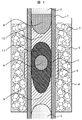
図1は、本発明に係る配管のき裂進展抑止方法の一実施例であり、配管1の縦断面図である。
FIG. 1 is a longitudinal sectional view of a
鉛直方向の配管1の内面に発生した貫通しないき裂2の進展を抑止するために、配管1の内部の水を除去し、気体3の環境中とする。
In order to suppress the progress of the
断熱材5を、配管1の外面におけるき裂2の位置に設置する。
The
断熱材5の管軸方向長さが短過ぎると、配管1が十分に拡管できず、長過ぎると氷11が、氷9,10栓を繋ぐように形成されないため、断熱材5は、配管1の直径と同程度から二倍程度の管軸方向長さとするのがよい。
If the length of the
次に、配管1に設置した断熱材5の鉛直下部および鉛直上部に氷9,10栓を形成するために十分な管軸方向長さを持った冷媒容器4を設置する。
Next, the refrigerant container 4 having a sufficient length in the tube axis direction for forming the
この冷媒容器4は、配管1にリング状に取り付けることが可能な容器を用いる。
The refrigerant container 4 is a container that can be attached to the
また、この冷媒容器4は、内部が空洞である。この空洞に、エチルアルコール6を断熱材5の鉛直下端程度まで注入する。なお、エチルアルコールに代えてメチルアルコールを用いてもよい。
The refrigerant container 4 is hollow inside. Into this cavity,
続いて、冷媒容器4に、ドライアイス7を投入する。ドライアイス7を投入することにより、冷媒容器4の内部における冷媒の液面が上昇するが、断熱材5の鉛直上端まで液面が上昇しないようにする。
Subsequently,
これにより、冷媒容器4が取り付けられた断熱材5の鉛直下部に対応する配管1を氷点下に冷却する。
Thereby, the
続いて、配管1の内部の鉛直上部より水8を管壁に沿って供給する。
Subsequently, water 8 is supplied along the pipe wall from the vertical upper part inside the
これにより、供給された水8が冷却され、配管1の内部の氷点下となった領域で凝固して、氷9栓が形成される。
As a result, the supplied water 8 is cooled and solidifies in the region below the freezing point inside the
氷9栓が形成されると、配管1の鉛直上部からの水8の供給により、配管1の内部に水8が溜まり始める。例えば、超音波探傷試験により、配管1の内部の水位を測定することで、氷9栓が形成されたことが確認できる。
When the
十分な時間が経過した後も、配管1の内部に水が溜まらない場合は、水8の供給量が過大で、氷9の成長速度と、水8の供給による氷9を溶かす速度が平衡している可能性があるので、水8の供給量を減少させる。
If water does not accumulate in the
配管1の内部に水8が冷媒容器4の上端程度まで溜まったことを確認した後に、水8の供給を止める。
After confirming that the water 8 has accumulated up to the upper end of the refrigerant container 4 in the
続いて、エチルアルコール6とドライアイス7を冷媒容器4に断熱材5の鉛直上部まで満たされるように投入する。このとき、室温のエチルアルコール6を冷媒容器4に投入すると、冷媒容器4内のドライアイス7が急激に気化するため、投入するエチルアルコール6にドライアイス7を入れて事前に冷却しておくと良い。
Subsequently, the
断熱材5の鉛直上部を冷却することにより、配管1の内部の水8が、冷却され凝固し始める。配管1が全て水8で満たされている場合に比べて、氷9栓により対流が抑制されるため、氷10栓が形成できる。
By cooling the vertical upper part of the
このとき、断熱材5を設置していたことにより、配管1の内部には氷9,10栓により水8が挟まれた領域が形成される。
At this time, since the
冷媒容器4の内部のドライアイス7が無くならないように適宜投入し続けると、氷9,10栓に挟まれた領域に氷11が形成され始める。水8から氷11へ変化する際の体積膨張により、氷9,10栓に挟まれた領域に圧力が生じ始める。
If the
この時、配管1の管壁内面に沿って、氷11が形成されることで、氷9,10栓に加わる管軸方向の力を支持する。
At this time,
配管1が別途実施した解析や実験により予め定めた量まで拡管したら、冷媒容器4を取り外す。
When the
しばらくすると、温度が上昇するので配管1の内部に形成された氷9,10,11が融解し、圧力が低下する。
After a while, the temperature rises, so the
上記手順により、配管1の内面におけるき裂2の先端近傍には、塑性変形が起こり、圧縮残留応力域が形成され、き裂2の先端は鈍化される。これによりき裂2の進展を抑止できる。
By the above procedure, plastic deformation occurs near the tip of the
図2の(a)〜(c)に、上記手順によるき裂2先端の状態の変化を示し、図2は、配管1の縦断面図のき裂2近傍を示す図である。
2A to 2C show changes in the state of the tip of the
図2(a)は、初期のき裂2の状態を示す。き裂2の先端は、非常に鋭く、引張残留応力域21が生じている。
FIG. 2A shows an
配管1の内部の圧力が上昇して、配管1に通常負荷する応力よりも大きい引張応力を負荷すると、図2(b)に示すように、き裂2が開口されて、き裂2の先端近傍にはより強く広い範囲に引張残留応力域21が形成される。
When the internal pressure of the
この時、き裂2の先端近傍では塑性変形が発生する。その後、配管1の内部の圧力が低下すると、き裂2の先端近傍の変形は、周囲の変形量が少ない領域に拘束されるため、図2(c)に示すように、き裂2の先端近傍に圧縮残留応力域22が形成される。
At this time, plastic deformation occurs near the tip of the
また、き裂2の先端が塑性変形することでき裂2は鈍化される。したがって、き裂2の進展が抑止される。
Further, the tip of the
更に、本発明に係る配管のき裂進展抑止方法における他の実施例について、図3を用いて説明する。 Furthermore, the other Example in the crack growth suppression method of piping which concerns on this invention is described using FIG.
図3は、二つの冷媒容器を用いる配管のき裂進展抑止方法の施工例について示すものであり、き裂2の鉛直下部と鉛直上部とに冷媒容器31,32をそれぞれ設置して、配管1の外面を冷却する実施例である。
FIG. 3 shows an example of construction of a crack propagation inhibiting method for a pipe using two refrigerant containers. The
配管1の内部の水を除去し、気体3環境中とする。
The water inside the
配管1の外面のき裂2位置に断熱材5を、き裂2の鉛直下部と鉛直上部とに冷媒容器31,32を設置する。
The
き裂2の鉛直下部に設置した冷媒容器31にエチルアルコール6およびドライアイス7を投入する。
続いて、配管1の鉛直上部より水8を管壁に沿って供給する。これにより、氷9栓が形成され、配管1の内部に水8が溜まり始める。
Subsequently, water 8 is supplied from the vertical upper part of the
配管1の内部に水8が、き裂2の鉛直上部に設置した冷媒容器32の上端程度まで溜まったことを確認した後に、水8の供給を止める。
After confirming that the water 8 has accumulated up to the upper end of the
続いて、エチルアルコール6とドライアイス7を、き裂2の鉛直上部に設置した冷媒容器32に投入する。これにより、氷10栓が形成され、配管1の内部には、氷9,10栓により水8が挟まれた領域が形成される。
Subsequently, the
冷媒容器31,32により、冷却を継続すると、氷9,10栓に挟まれた領域に氷11が形成され始め、氷9,10栓に挟まれた領域の圧力が上昇し始める。
When the cooling is continued by the
これにより、断熱材5を設置した位置で配管1が拡管する。
Thereby, the
配管1が予め定めた量まで拡管したら、冷媒容器31,32を取り外す。
When the
しばらくすると、温度が上昇するので配管1の内部に形成された氷9,10,11が融解し、圧力が低下する。
After a while, the temperature rises, so the
以上のように、これら実施例によれば、配管の内部を気体環境中として、鉛直上部からの水の供給により氷栓を形成することで、水の熱伝達および対流を低減することができ、直径の大きい配管に氷栓を形成可能となる。 As described above, according to these examples, the inside of the pipe is in a gas environment, and by forming an ice plug by supplying water from the vertical upper part, heat transfer and convection of water can be reduced, An ice plug can be formed on a pipe having a large diameter.
また、き裂の鉛直下部および鉛直上部からの冷却により、氷栓で閉じられた領域に管壁に沿って氷栓を繋ぐように氷を形成することで、水圧の上昇により生じる管軸方向の圧力に対して氷栓が支持され、直径の大きい配管の内面に発生した貫通しないき裂を抑止する施工が可能となる。 In addition, by cooling from the vertical lower part and upper part of the crack, ice is formed in the region closed by the ice plug so as to connect the ice plug along the tube wall, so that The ice plug is supported against the pressure, and it is possible to perform construction that suppresses a non-penetrating crack generated on the inner surface of the pipe having a large diameter.
本発明のき裂進展抑止方法は、応力腐食割れや疲労によりき裂が生じたオーステナイト系ステンレス鋼などの配管に利用可能である。 The crack growth inhibiting method of the present invention can be used for piping such as austenitic stainless steel in which cracks have occurred due to stress corrosion cracking or fatigue.
1 配管
2 き裂
3 気体
4,31,32 冷媒容器
5 断熱材
6 エチルアルコール
7 ドライアイス
8 水
9,10,11 氷
21 引張残留応力域
22 圧縮残留応力域
1
Claims (4)
前記配管の内部を気体環境中とし、
前記き裂の鉛直下部を氷点下に冷却し、
前記配管の内面の管壁に沿って鉛直上部より水を供給して氷栓を形成し、
前記き裂の鉛直上部まで水が溜め、
前記き裂の鉛直上部を氷点下に冷却し、
前記き裂が形成されている位置に溜められた水を氷点下に冷却することを特徴とする配管のき裂進展抑止方法。 In a method for inhibiting crack propagation in a vertical pipe having a minute crack that does not penetrate the inner surface,
The inside of the pipe is in a gaseous environment,
Cooling the vertical bottom of the crack below freezing point,
Supply water from the vertical upper part along the pipe wall on the inner surface of the pipe to form an ice plug,
Water accumulates up to the vertical top of the crack,
Cooling the vertical top of the crack below freezing;
A method for inhibiting crack propagation in a pipe, wherein water accumulated at a position where the crack is formed is cooled below freezing point.
前記き裂が形成されている位置は、配管の外部から、直接、冷却せず、前記き裂の鉛直上部及び鉛直下部の配管の外部から冷却し、その冷却熱によって、前記き裂が形成されている位置を氷点下に冷却することを特徴とする配管のき裂進展抑止方法。 In claim 1,
The position where the crack is formed is not cooled directly from the outside of the pipe, but is cooled from the outside of the pipe at the vertical upper and lower parts of the crack, and the crack is formed by the cooling heat. A method for inhibiting crack propagation in a pipe, characterized by cooling the position below freezing point.
前記き裂が形成されている位置近傍の配管の外部に、断熱材を形成し、前記断熱材の鉛直下部および鉛直上部を冷却することを特徴とする配管のき裂進展抑止方法。 In claim 1,
A method for inhibiting crack propagation in a pipe, comprising forming a heat insulating material outside a pipe near a position where the crack is formed, and cooling a vertical lower portion and a vertical upper portion of the heat insulating material.
前記き裂の鉛直下部および鉛直上部に形成された氷栓により、前記き裂が形成されている位置近傍に溜められた水が、氷栓で閉じられた領域を形成した後に、前記領域に、前記配管の内部の管壁に沿って氷栓を形成することを特徴とする配管のき裂進展抑止方法。 In claim 1,
After the water collected in the vicinity of the position where the crack is formed by the ice plugs formed at the vertical lower part and the vertical upper part of the crack, the area closed by the ice plug is formed in the area. An ice plug is formed along a pipe wall inside the pipe.
Priority Applications (1)
| Application Number | Priority Date | Filing Date | Title |
|---|---|---|---|
| JP2008089149A JP4972595B2 (en) | 2008-03-31 | 2008-03-31 | Method for inhibiting crack growth in piping |
Applications Claiming Priority (1)
| Application Number | Priority Date | Filing Date | Title |
|---|---|---|---|
| JP2008089149A JP4972595B2 (en) | 2008-03-31 | 2008-03-31 | Method for inhibiting crack growth in piping |
Publications (2)
| Publication Number | Publication Date |
|---|---|
| JP2009243545A true JP2009243545A (en) | 2009-10-22 |
| JP4972595B2 JP4972595B2 (en) | 2012-07-11 |
Family
ID=41305696
Family Applications (1)
| Application Number | Title | Priority Date | Filing Date |
|---|---|---|---|
| JP2008089149A Active JP4972595B2 (en) | 2008-03-31 | 2008-03-31 | Method for inhibiting crack growth in piping |
Country Status (1)
| Country | Link |
|---|---|
| JP (1) | JP4972595B2 (en) |
Cited By (2)
| Publication number | Priority date | Publication date | Assignee | Title |
|---|---|---|---|---|
| JP2011093041A (en) * | 2009-10-29 | 2011-05-12 | Kobe Steel Ltd | Local cooling method |
| JP2014091948A (en) * | 2012-11-02 | 2014-05-19 | Daiyu Freeze:Kk | Freezing method of fluid transport pipeline |
Citations (10)
| Publication number | Priority date | Publication date | Assignee | Title |
|---|---|---|---|---|
| JPS5673293A (en) * | 1979-11-16 | 1981-06-17 | Hitachi Ltd | Ice plug construction of pipings |
| JPS5775296A (en) * | 1980-10-29 | 1982-05-11 | Mitsubishi Heavy Ind Ltd | Method for improving residual stress of welded joint part of pipe |
| JPS58184391A (en) * | 1982-04-19 | 1983-10-27 | 三菱重工業株式会社 | Method of pressing partial section in piping |
| JPS61171994A (en) * | 1985-01-23 | 1986-08-02 | 石川島播磨重工業株式会社 | Method of closing fluid in piping |
| JPS6326490A (en) * | 1986-07-16 | 1988-02-04 | 石川島播磨重工業株式会社 | Method of closing piping |
| JPH04131591A (en) * | 1990-09-21 | 1992-05-06 | Hitachi Ltd | Carbon steel piping freezing method |
| JPH04327089A (en) * | 1991-04-24 | 1992-11-16 | Hitachi Ltd | Cooling jacket and ice plug method |
| JPH1038181A (en) * | 1996-07-25 | 1998-02-13 | Mitsubishi Heavy Ind Ltd | Ice plug forming device for vertical pipe |
| JP2000065281A (en) * | 1998-08-18 | 2000-03-03 | Hitachi Plant Eng & Constr Co Ltd | Determining method for ice plug completion in piping freezing construction method |
| JP2005095948A (en) * | 2003-09-26 | 2005-04-14 | Hitachi Ltd | Method for improving residual stress of piping |
-
2008
- 2008-03-31 JP JP2008089149A patent/JP4972595B2/en active Active
Patent Citations (10)
| Publication number | Priority date | Publication date | Assignee | Title |
|---|---|---|---|---|
| JPS5673293A (en) * | 1979-11-16 | 1981-06-17 | Hitachi Ltd | Ice plug construction of pipings |
| JPS5775296A (en) * | 1980-10-29 | 1982-05-11 | Mitsubishi Heavy Ind Ltd | Method for improving residual stress of welded joint part of pipe |
| JPS58184391A (en) * | 1982-04-19 | 1983-10-27 | 三菱重工業株式会社 | Method of pressing partial section in piping |
| JPS61171994A (en) * | 1985-01-23 | 1986-08-02 | 石川島播磨重工業株式会社 | Method of closing fluid in piping |
| JPS6326490A (en) * | 1986-07-16 | 1988-02-04 | 石川島播磨重工業株式会社 | Method of closing piping |
| JPH04131591A (en) * | 1990-09-21 | 1992-05-06 | Hitachi Ltd | Carbon steel piping freezing method |
| JPH04327089A (en) * | 1991-04-24 | 1992-11-16 | Hitachi Ltd | Cooling jacket and ice plug method |
| JPH1038181A (en) * | 1996-07-25 | 1998-02-13 | Mitsubishi Heavy Ind Ltd | Ice plug forming device for vertical pipe |
| JP2000065281A (en) * | 1998-08-18 | 2000-03-03 | Hitachi Plant Eng & Constr Co Ltd | Determining method for ice plug completion in piping freezing construction method |
| JP2005095948A (en) * | 2003-09-26 | 2005-04-14 | Hitachi Ltd | Method for improving residual stress of piping |
Cited By (2)
| Publication number | Priority date | Publication date | Assignee | Title |
|---|---|---|---|---|
| JP2011093041A (en) * | 2009-10-29 | 2011-05-12 | Kobe Steel Ltd | Local cooling method |
| JP2014091948A (en) * | 2012-11-02 | 2014-05-19 | Daiyu Freeze:Kk | Freezing method of fluid transport pipeline |
Also Published As
| Publication number | Publication date |
|---|---|
| JP4972595B2 (en) | 2012-07-11 |
Similar Documents
| Publication | Publication Date | Title |
|---|---|---|
| JP4448791B2 (en) | Method and apparatus for improving residual stress in piping | |
| JP2005164034A (en) | Liquefied natural gas transporting pipe | |
| JP4972595B2 (en) | Method for inhibiting crack growth in piping | |
| BRPI0902823B1 (en) | connecting piece between a cracking pipe and a cooling pipe and method for connecting a cracking pipe to a cooling pipe | |
| JP5367558B2 (en) | How to improve residual stress in piping | |
| JP2009050906A (en) | Method for improving residual stress of small diameter piping | |
| CN103672401A (en) | Supporting structure of low-temperature liquid heat-insulating tank container | |
| US8978433B2 (en) | Pipe diameter expansion apparatus and pipe diameter expansion method | |
| JP5237750B2 (en) | How to improve residual stress in piping | |
| JP6367681B2 (en) | Piping residual stress improvement method, antifreeze liquid supply method between ice plugs, and piping residual stress improvement device | |
| JP4300085B2 (en) | How to improve residual stress in piping | |
| JP2008238190A (en) | Method for improving residual stress of piping | |
| BRPI0809092A2 (en) | METHODS OF PROVIDING A DUPLEX STAINLESS STEEL STRIP FOR A FLEXIBLE PIPE ARRIVAL LAYER AND PROVIDING A DUPLEX STAINLESS STEEL PIECE BETWEEN YOU. | |
| CN203948802U (en) | A kind of composite bimetal pipe | |
| CN207263321U (en) | Power plant's temperature sleeves clamp device | |
| Mills | The freezing bomb | |
| JP4857375B2 (en) | Equipment for improving residual stress in piping | |
| JP2006258610A (en) | Apparatus and method for inspecting thickness reduction of laid pipe with heat insulating member | |
| JPH0129631B2 (en) | ||
| JP6447196B2 (en) | Manufacturing method of titanium welded pipe | |
| RU2683449C1 (en) | Method of protecting metal structures from negative effect of external environment (versions) | |
| Ku et al. | Effectiveness of Excavate and Weld Repair on a Large Diameter Piping Dissimilar Metal Weld by Finite Element Analysis | |
| JP2010042452A (en) | Method for improving residual stress of small diameter piping | |
| JP5357986B2 (en) | Method of water cooling inside nozzle | |
| JP5740816B2 (en) | Piping freezing method |
Legal Events
| Date | Code | Title | Description |
|---|---|---|---|
| A621 | Written request for application examination |
Free format text: JAPANESE INTERMEDIATE CODE: A621 Effective date: 20100305 |
|
| A521 | Written amendment |
Free format text: JAPANESE INTERMEDIATE CODE: A523 Effective date: 20100305 |
|
| A977 | Report on retrieval |
Free format text: JAPANESE INTERMEDIATE CODE: A971007 Effective date: 20111116 |
|
| A131 | Notification of reasons for refusal |
Free format text: JAPANESE INTERMEDIATE CODE: A131 Effective date: 20111220 |
|
| A521 | Written amendment |
Free format text: JAPANESE INTERMEDIATE CODE: A523 Effective date: 20120206 |
|
| TRDD | Decision of grant or rejection written | ||
| A01 | Written decision to grant a patent or to grant a registration (utility model) |
Free format text: JAPANESE INTERMEDIATE CODE: A01 Effective date: 20120313 |
|
| A01 | Written decision to grant a patent or to grant a registration (utility model) |
Free format text: JAPANESE INTERMEDIATE CODE: A01 |
|
| A61 | First payment of annual fees (during grant procedure) |
Free format text: JAPANESE INTERMEDIATE CODE: A61 Effective date: 20120409 |
|
| FPAY | Renewal fee payment (event date is renewal date of database) |
Free format text: PAYMENT UNTIL: 20150413 Year of fee payment: 3 |
|
| R150 | Certificate of patent or registration of utility model |
Ref document number: 4972595 Country of ref document: JP Free format text: JAPANESE INTERMEDIATE CODE: R150 Free format text: JAPANESE INTERMEDIATE CODE: R150 |