JP2009236832A - Monitoring method and device for dissolved pollutant - Google Patents
Monitoring method and device for dissolved pollutant Download PDFInfo
- Publication number
- JP2009236832A JP2009236832A JP2008085930A JP2008085930A JP2009236832A JP 2009236832 A JP2009236832 A JP 2009236832A JP 2008085930 A JP2008085930 A JP 2008085930A JP 2008085930 A JP2008085930 A JP 2008085930A JP 2009236832 A JP2009236832 A JP 2009236832A
- Authority
- JP
- Japan
- Prior art keywords
- water
- light
- fluorescence
- wavelength
- measured
- Prior art date
- Legal status (The legal status is an assumption and is not a legal conclusion. Google has not performed a legal analysis and makes no representation as to the accuracy of the status listed.)
- Pending
Links
Images


Classifications
-
- Y—GENERAL TAGGING OF NEW TECHNOLOGICAL DEVELOPMENTS; GENERAL TAGGING OF CROSS-SECTIONAL TECHNOLOGIES SPANNING OVER SEVERAL SECTIONS OF THE IPC; TECHNICAL SUBJECTS COVERED BY FORMER USPC CROSS-REFERENCE ART COLLECTIONS [XRACs] AND DIGESTS
- Y02—TECHNOLOGIES OR APPLICATIONS FOR MITIGATION OR ADAPTATION AGAINST CLIMATE CHANGE
- Y02A—TECHNOLOGIES FOR ADAPTATION TO CLIMATE CHANGE
- Y02A20/00—Water conservation; Efficient water supply; Efficient water use
- Y02A20/20—Controlling water pollution; Waste water treatment
Abstract
Description
本発明は、例えば下水、工場廃水、環境水(河川水、湖沼水、海水など)の水質として水中に溶存する汚濁物質濃度を、オンサイトにて、無薬注かつ連続的にモニタリングする方法に関するものである。 The present invention relates to a method for on-site non-chemical injection and continuous monitoring of the concentration of pollutants dissolved in water as sewage, factory waste water, environmental water (river water, lake water, sea water, etc.). Is.
従来、公共水域においては、水質保全のために環境水の水質測定が行われており、下水処理場や工場、事業所などでは、水質汚濁防止法にもとづいた種々の規制値を遵守するために、処理水や排水の水質測定が行われている。
これらの水質は、時間的な変動が大きいため、連続的にモニタリングすることが望ましい。また、下水は工場廃水の汚濁物質を除去する処理施設などにおいては、施設に流入する原水の水質変動を捉えることができれば、水質に応じた運転条件の設定が可能となり、適正な運転管理、消費電力や消費薬剤の削減などが可能になる。
Conventionally, in public water areas, the quality of environmental water has been measured to preserve water quality, and in order to comply with various regulations based on the Water Pollution Control Law at sewage treatment plants, factories, offices, etc. The quality of treated water and wastewater is measured.
Since these water qualities vary greatly over time, it is desirable to monitor them continuously. In addition, in sewage treatment facilities that remove pollutants from factory wastewater, if fluctuations in the quality of the raw water flowing into the facility can be captured, operating conditions can be set according to the water quality, and appropriate operation management and consumption It will be possible to reduce power consumption and chemical consumption.
しかしながら、これらの水質分析は、手順が複雑である上に専門的な技術が必要とされることから、連続的な水質の監視は難しいという問題があった。
そこで近年、試料水に励起光を照射したときに試料水から出てくる蛍光の強度を測定することで、水中の汚濁物質濃度を求める方法が注目されている。
However, these water quality analyzes have a problem that it is difficult to continuously monitor the water quality because the procedure is complicated and specialized techniques are required.
Therefore, in recent years, attention has been focused on a method for determining the concentration of pollutants in water by measuring the intensity of fluorescence emitted from the sample water when the sample water is irradiated with excitation light.
この蛍光強度を測定する方法としては、特許文献1には、励起波長270nm乃至370nmの光を被検査対象となる水に照射し、その分光スペクトル中の380nm乃至480nmの蛍光波長を測定することにより、前記水中のトリハロメタン生成能あるいはフミン質濃度を測定することを特徴とする水質検査方法が開示されている。
As a method for measuring the fluorescence intensity,
特許文献2には、予め設定されている波長の励起光を発生する励起光発生装置と、特定波長範囲内の各波長光を抽出する波長光抽出器を有し、前記励起光発生装置から照射された励起光によって有機物測定対象となる被検水から発せられる蛍光に含まれる特定波長範囲内の各波長光を順次、または一括して抽出して光強度を測定し、この測定結果に基づき、前記被検水中の有機物濃度を測定する濃度測定装置と、本測定装置を備えたことを特徴とする蛍光分析水質測定システムが開示されている。 Patent Document 2 includes a pumping light generator that generates pumping light having a preset wavelength, and a wavelength light extractor that extracts each wavelength of light within a specific wavelength range, and is irradiated from the pumping light generator. Measure the light intensity by extracting each wavelength light within a specific wavelength range included in the fluorescence emitted from the test water that is the organic matter measurement target by the excited light, or collectively and based on the measurement result, There is disclosed a concentration measuring device for measuring the concentration of organic matter in the test water and a fluorescence analysis water quality measuring system comprising the measuring device.
特許文献3には、被測定水の濁質を除去するための孔径5μm以下のフィルタと、前記フィルタによるフィルタリング後の被測定水に光を照射する照射手段と、前記照射手段によって光の照射された被測定水から発生する蛍光の強度を測定する蛍光測定手段と、前記蛍光測定手段によって測定された蛍光の強度に基づいて、被測定水中の有機ハロゲン化合物の前駆物質に関するデータを測定するデータ測定手段とを具備したことを特徴とする水質測定装置が開示されている。
In
また、特許文献4には、試料水に波長の異なる第1、第2の励起光を照射し、試料水が発する波長の異なる第1、第2の蛍光の強度を測定することに基づいて、試料水の第1、第2の水質指標を測定することを特徴とする水質測定方法が開示されている。 Further, Patent Document 4 is based on irradiating sample water with first and second excitation lights having different wavelengths, and measuring the intensity of first and second fluorescence having different wavelengths emitted from the sample water. There is disclosed a water quality measuring method characterized by measuring first and second water quality indexes of sample water.
上記の従来の蛍光測定法は、オンサイトにおける連続的な水質のモニタリングに適していると考えられるが、試料水中の懸濁物質濃度が増加すると、励起のための照射光が懸濁物質により散乱し、同じ溶存汚濁物質濃度の試料水であっても、出てくる蛍光強度が変化する。このために、別途、濁度などを測定して補正を行うなどの必要が生じる。しかし、蛍光測定法で用いる照射光と濁度などの測定に用いる光は波長帯が異なる。2つの異なる波長帯の光は、散乱特性あるいは吸収特性が異なり、混在する懸濁物質が換わると測定値が大きく変化してしまうことが知られている。 The above conventional fluorescence measurement method is considered to be suitable for continuous on-site water quality monitoring. However, as the suspended solid concentration in the sample water increases, the irradiation light for excitation is scattered by the suspended solid. However, even if the sample water has the same dissolved pollutant concentration, the intensity of the emitted fluorescence changes. For this reason, it is necessary to separately perform correction by measuring turbidity and the like. However, the wavelength band is different between the irradiation light used in the fluorescence measurement method and the light used for measurement of turbidity. It is known that the light of two different wavelength bands has different scattering characteristics or absorption characteristics, and the measured value changes greatly when the mixed suspended matter is changed.
このため、特許文献2には、フィルターなどを用いて懸濁物質を事前に除去する方法などが開示されている。この方法の場合、懸濁物質濃度が高いとフィルターがすぐに閉塞するなどの問題が生じ、メンテナンス性が著しく低下する。 For this reason, Patent Document 2 discloses a method of removing suspended substances in advance using a filter or the like. In the case of this method, when the suspended substance concentration is high, problems such as the filter being clogged immediately occur, and the maintainability is significantly lowered.
本発明では、以上の問題を解決するため、試料水に励起光を照射して出てくる蛍光強度を測定すると同時に、水分子のラマン散乱光(照射光の波長より約15%長波長の散乱光)の強度も併せて測定を行い、水分子のラマン散乱光強度が小さい場合は、同じ溶存汚濁物質濃度でも発する蛍光強度が小さくなる関係から、補正を行うこととした。 In the present invention, in order to solve the above problems, the intensity of fluorescence emitted by irradiating the sample water with excitation light is measured, and at the same time, Raman scattered light of water molecules (scattering of about 15% longer than the wavelength of the irradiated light). The light intensity was also measured, and when the Raman scattered light intensity of water molecules was small, correction was performed because the fluorescence intensity emitted was small even at the same dissolved pollutant concentration.
試料水の懸濁性物質濃度が高くなると、照射した光が懸濁性物質により散乱し、溶存性の汚濁物質に対する有効照射量が減少するため、発生する蛍光が減少する。また、発生した蛍光も懸濁性物質により散乱してしまい、検出量が減少することとなる。
この散乱度合いを、他の波長帯の光を用いて測定した濁度などで推定すると、散乱特性あるいは吸収特性が異なるため、正しい推定が行えないことがわかった。
そこで、濃度が既知の水分子によるラマン散乱光強度を検出して補正に用いることにより、有効照射量を正確に把握することができ、溶存汚濁物質濃度を精度良くモニタリングすることが可能となる。
When the concentration of the suspending substance in the sample water is increased, the irradiated light is scattered by the suspending substance, and the effective irradiation amount with respect to the dissolved pollutant is reduced, so that the generated fluorescence is reduced. Also, the generated fluorescence is scattered by the suspended substance, and the detection amount is reduced.
When this degree of scattering was estimated by turbidity measured using light in other wavelength bands, it was found that correct estimation could not be performed because of different scattering characteristics or absorption characteristics.
Therefore, by detecting the Raman scattered light intensity of water molecules having a known concentration and using it for correction, the effective irradiation amount can be accurately grasped, and the dissolved pollutant concentration can be accurately monitored.
モニタリング対象とする汚濁物質濃度が1000ppm以下の場合は、溶存汚濁物質濃度とそれから出る蛍光強度は1次の相関関係があり、
a、b:定数
Sf:蛍光強度
で表すことができる。そして、下記の式2に水によるラマン散乱光強度(Sr)の補正項を加えることで、精度良くモニタリングすることが可能となる。
本法では、懸濁性物質が数百ppmのオーダーで存在する試料水も、フィルタなどによるろ過は必要が無く、メンテナンス性が良い。また、光源が励起光用の1つであるため、別途濁度測定用の光源を有する方法より、光源強度補正のためのキャリブレーションの手間も必要なく、補正の精度も高くなる。励起用の光と別の波長(たとえば濁度計は600nm周辺波長を使用)の光を照射して、励起光や蛍光の減衰を補正する方法に比べ、高い精度の水質モニタリングが可能となる。 In this method, sample water in which suspended substances are present on the order of several hundred ppm does not need to be filtered with a filter or the like, and is easy to maintain. In addition, since the light source is one for excitation light, calibration is not required for light source intensity correction and the correction accuracy is higher than that of a method having a separate turbidity measurement light source. Compared with a method of correcting the attenuation of excitation light or fluorescence by irradiating light of a wavelength different from that of excitation light (for example, a turbidimeter uses a wavelength around 600 nm), water quality monitoring with higher accuracy is possible.
本発明により、懸濁性物質が多く含まれる試料水を対象としても、溶存性の汚濁物質濃度を正確にモニタリングすることができるようになる。特に、下水や工場廃水の汚濁物質を除去する処理施設などにおいては、施設に流入する原水の水質変動を捉えることができれば、水質に応じた運転条件の設定が可能となり、適正な運転管理、消費電力や消費薬剤の削減などが可能になる。 According to the present invention, even when sample water containing a large amount of suspended substances is used, the concentration of dissolved pollutants can be accurately monitored. In particular, in treatment facilities that remove pollutants from sewage and factory wastewater, if changes in the quality of raw water flowing into the facility can be captured, it is possible to set operating conditions according to the water quality, and to ensure proper operation management and consumption. It will be possible to reduce power consumption and chemical consumption.
本発明は、懸濁性物質が存在する水の水質を測定するものであり、対象となる水は、例えば、下水、工場廃水、環境水(河川水、湖沼水、海水等)などである。測定対象となる溶存汚濁物質は、COD(化学的酸素要求量)、油分、フミン質、NO3−イオン等である。濃度としては、CODの場合は、10〜1000程度、通常100〜500程度、懸濁性物質の濃度は50〜1000mg/l程度、通常100〜500mg/l程度である。この濃度はJISあるいは下水試験法で測定したものである。 The present invention measures the quality of water in which suspended substances exist, and the target water is, for example, sewage, factory wastewater, environmental water (river water, lake water, seawater, etc.), and the like. The dissolved pollutants to be measured are COD (chemical oxygen demand), oil, humic substances, NO 3− ions and the like. In the case of COD, the concentration is about 10 to 1000, usually about 100 to 500, and the concentration of the suspended substance is about 50 to 1000 mg / l, usually about 100 to 500 mg / l. This concentration is measured by JIS or sewage test method.
上記の試料水に照射する光は、測定対象の溶存汚濁物質を励起して蛍光を発光させる波長のものであり、CODの場合は、220〜350nm程度、好ましくは260〜290nm程度の波長の光である。
光源に含まれる上記以外の波長の光は、測定に影響を与えない波長については除去しなくてもよいが、少なくとも測定対象の蛍光および励起光の水分子によるラマン散乱光と同じ波長の領域は除去しておくことが好ましい。除去手段は常法によればよく、例えば、フィルターやプリズムが用いられる。
The light irradiated to the sample water is of a wavelength that excites the dissolved pollutant to be measured and emits fluorescence. In the case of COD, the light has a wavelength of about 220 to 350 nm, preferably about 260 to 290 nm. It is.
Light with a wavelength other than the above contained in the light source may not be removed for wavelengths that do not affect the measurement, but at least the region of the same wavelength as the Raman scattered light by the water molecules of the fluorescence and excitation light to be measured It is preferable to remove it. The removing means may be a conventional method, for example, a filter or a prism is used.
測定する蛍光およびラマン散乱光はそれらの全波長を対象としてもよいが、通常は、その一部であり、光度が強く、他の影響を受けない波長が選択される。
本発明の方法は、溶存汚濁物質の濃度を蛍光強度で測定し、その際の懸濁性物質による影響を水分子によるラマン散乱光の強度で補正する方法である。
そこで、あらかじめ、溶存汚濁物質濃度および懸濁性物質濃度の異なる3検体以上、好ましくは10検体以上の試料水を準備し、溶存汚濁物質濃度(Ck)と蛍光強度(Sfk)および水によるラマン散乱光強度(Srk)を測定する。
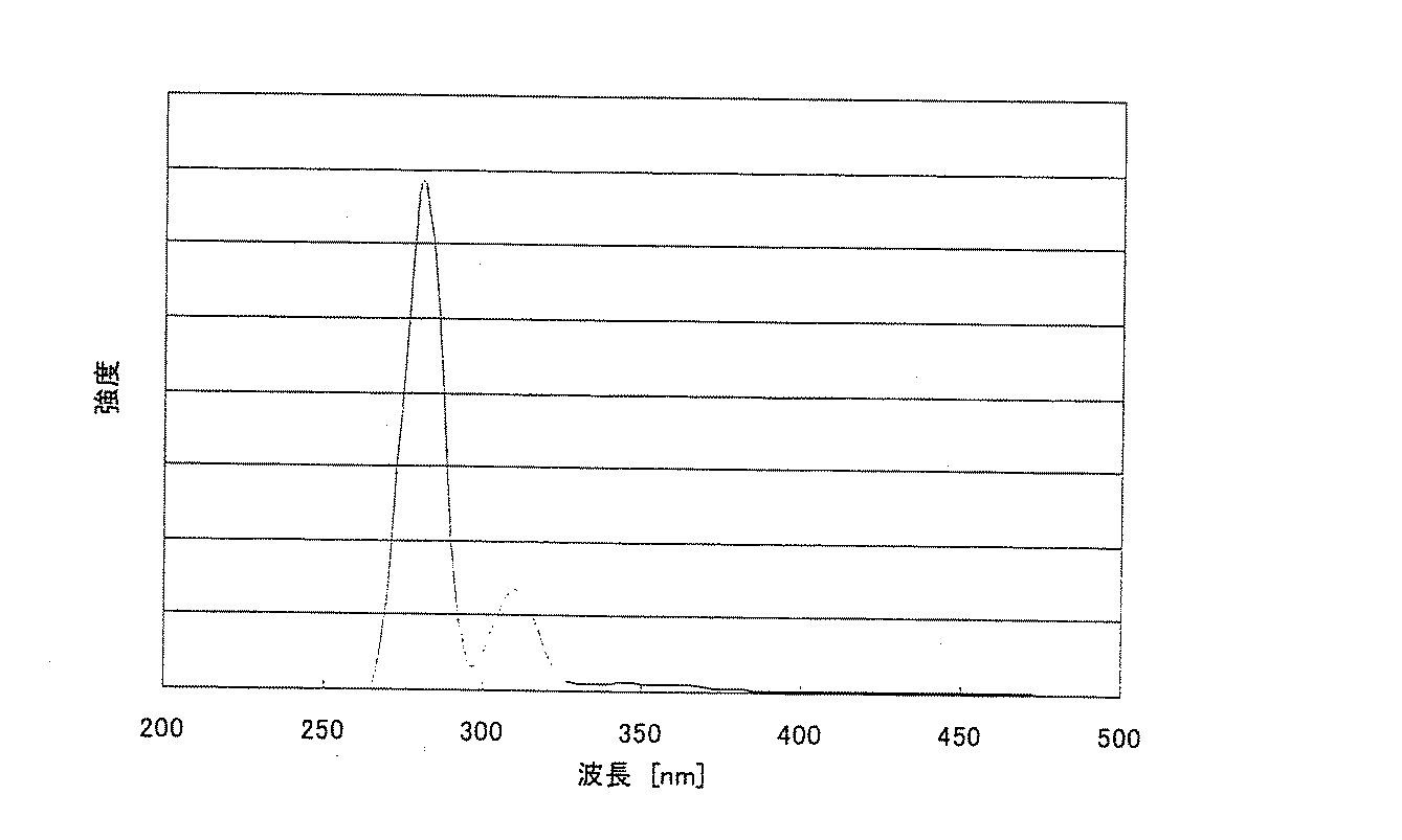
ラマン散乱光は、入射光の振動数(V)と照射された物質に固有の振動数(V1、V2・・・)が総合した振動数(VI1、VI2・・・)の散乱光であるが、図3に示すように、最も強度の大きなものを測定するのがよい。この散乱光は、前述のように水分子の場合は照射光の波長より約15%長波長の散乱光である。
The fluorescence and Raman scattered light to be measured may be targeted for all their wavelengths, but are usually a part of them and a wavelength that is strong and has no other influence is selected.
The method of the present invention is a method in which the concentration of dissolved pollutant is measured by fluorescence intensity, and the influence of the suspended substance at that time is corrected by the intensity of Raman scattered light by water molecules.
Therefore, sample water of 3 samples or more, preferably 10 samples or more having different dissolved pollutant concentration and suspending substance concentration is prepared in advance, and depending on the dissolved pollutant concentration (C k ), fluorescence intensity (Sf k ), and water The Raman scattered light intensity (Sr k ) is measured.
The Raman scattered light is scattered at a frequency (VI 1 , VI 2 ...) Obtained by combining the frequency (V) of incident light and the frequencies (V 1 , V 2 ...) Inherent to the irradiated material. Although it is light, as shown in FIG. 3, it is good to measure a thing with the largest intensity | strength. As described above, in the case of water molecules, this scattered light is scattered light having a wavelength about 15% longer than the wavelength of the irradiation light.
これらaとbの定数が定まったら、試料水の蛍光とラマン散乱光の強度測定を行い、それらの測定値から溶存汚濁物質の濃度を求めることができる。
図1に、本発明法で使用される装置の一例の概略構成を示す。溶存汚濁物質濃度をモニタリングすべき試料水1に、励起光3を照射する光源2、試料水より出てくる蛍光および水によるラマン散乱光4を観測する受光器5、観測された蛍光強度および水によるラマン散乱光強度を用いて、換算式(式2)により溶存汚濁物質濃度を算出する演算部6、および表示部7からなる。
When the constants a and b are determined, the fluorescence of the sample water and the intensity of Raman scattered light are measured, and the concentration of the dissolved pollutant can be obtained from the measured values.
FIG. 1 shows a schematic configuration of an example of an apparatus used in the method of the present invention.
また、受光器5は、蛍光と水によるラマン散乱光が同時に入射するため、ハーフミラーや光学フィルタなどを用いて、光学的に分光し、各々の強度を観測できる機構とする。
The
図1に示す装置を用いた。受光器は図2に示す構図とした。入光部51より蛍光と水によるラマン散乱光が入射する。入射した光をハーフミラー52により50%ずつに分け、片方の光は蛍光の波長に併せたバンドパスフィルタ55を通り、フォトマルにて蛍光強度が観測される。もう一方の光は水によるラマン散乱光波長用バンドパスフィルタ56を通り、フォトマル57にて強度が測定される。
The apparatus shown in FIG. 1 was used. The light receiver has the composition shown in FIG. Raman scattered light due to fluorescence and water enters from the
都市下水処理場の曝気槽流入水を試料水として、溶存性の化学的酸素要求量(COD)をモニタリングした。試料水は処理前の下水であるため懸濁性物質が多く含まれ、懸濁性物質濃度(SS)として100〜200mg/Lであった。CODは下水試験に準拠した方法にて測定した。
紫外線(波長275〜285nm)を照射したときに出てくる蛍光と溶存性のCODに相関があることを次のように確認した。
Dissolved chemical oxygen demand (COD) was monitored using the inflow water from an aeration tank of a municipal sewage treatment plant as sample water. Since the sample water was sewage before treatment, it contained a lot of suspending substances, and the suspending substance concentration (SS) was 100 to 200 mg / L. COD was measured by a method based on a sewage test.
It was confirmed as follows that there was a correlation between fluorescence emitted when irradiated with ultraviolet rays (wavelength 275 to 285 nm) and dissolved COD.
蛍光は355〜365nmの波長の強度を測定した。COD濃度に対して観測した蛍光強度をプロットした結果を図4に示す。この時SS濃度は100〜200mg/Lと変化が大きく、この影響によりCOD濃度と簡素空された蛍光強度との相関は弱くなっていた。 The fluorescence measured the intensity | strength of the wavelength of 355-365 nm. The results of plotting the observed fluorescence intensity against the COD concentration are shown in FIG. At this time, the SS concentration varied greatly from 100 to 200 mg / L. Due to this influence, the correlation between the COD concentration and the simply empty fluorescence intensity was weak.
これに対して、あらかじめ、対象下水処理場の曝気槽流入水を1時間おきに1日間、計24回サンプリングし、COD濃度(Ck)と蛍光強度(Sfk)およびラマン散乱光強度(Srk)を測定した。この結果をもとに、
このとき307.5〜312.5nmの波長の強度を測定し、水によるラマン散乱光の強度とした。
観測されたラマン散乱光強度を用いて補正を行った結果をプロットしたものを図5に示す。
In contrast, the inflow water from the aeration tank of the target sewage treatment plant was sampled 24 times in total every other day for one day, and the COD concentration (C k ), fluorescence intensity (Sf k ), and Raman scattered light intensity (Sr k ) was measured. Based on this result,
At this time, the intensity of a wavelength of 307.5 to 312.5 nm was measured and used as the intensity of Raman scattered light by water.
FIG. 5 shows a plot of the results of correction using the observed Raman scattered light intensity.
図5に示すように、本発明で得られた値はCODの実測値とよい相関を示した。 As shown in FIG. 5, the value obtained by the present invention showed a good correlation with the measured value of COD.
本発明の方法は、懸濁性物質が存在する水の水質をそのまま高い信頼性で測定できるので、下水、工場廃水、河川水などの水質測定に利用できる。 Since the method of the present invention can measure the quality of water containing suspended substances with high reliability as it is, it can be used for measuring the quality of sewage, factory wastewater, river water and the like.
1 試料水
2 励起光光源
3 励起光
4 蛍光および水によるラマン散乱光
5 受光器
6 演算部
7 演算結果表示装置
51 入光部
52 ハーフミラー
54 ミラー
55 蛍光の波長用バンドパスフィルタ
56 水によるラマン散乱光波長用バンドパスフィルタ
57 フォトマル
DESCRIPTION OF
Claims (2)
Priority Applications (1)
| Application Number | Priority Date | Filing Date | Title |
|---|---|---|---|
| JP2008085930A JP2009236832A (en) | 2008-03-28 | 2008-03-28 | Monitoring method and device for dissolved pollutant |
Applications Claiming Priority (1)
| Application Number | Priority Date | Filing Date | Title |
|---|---|---|---|
| JP2008085930A JP2009236832A (en) | 2008-03-28 | 2008-03-28 | Monitoring method and device for dissolved pollutant |
Publications (1)
| Publication Number | Publication Date |
|---|---|
| JP2009236832A true JP2009236832A (en) | 2009-10-15 |
Family
ID=41250946
Family Applications (1)
| Application Number | Title | Priority Date | Filing Date |
|---|---|---|---|
| JP2008085930A Pending JP2009236832A (en) | 2008-03-28 | 2008-03-28 | Monitoring method and device for dissolved pollutant |
Country Status (1)
| Country | Link |
|---|---|
| JP (1) | JP2009236832A (en) |
Cited By (3)
| Publication number | Priority date | Publication date | Assignee | Title |
|---|---|---|---|---|
| JP2014526709A (en) * | 2011-09-23 | 2014-10-06 | ナルコ カンパニー | Method for monitoring and controlling wastewater treatment streams |
| KR20150122086A (en) * | 2014-04-21 | 2015-10-30 | (주)링크옵틱스 | green tide and red tide remote monitoring apparatus |
| US10302564B2 (en) | 2016-05-19 | 2019-05-28 | Fuji Electric Co., Ltd. | Water quality analyzer |
Citations (4)
| Publication number | Priority date | Publication date | Assignee | Title |
|---|---|---|---|---|
| JPS63263458A (en) * | 1987-04-21 | 1988-10-31 | Shimadzu Corp | Base sequence determining apparatus |
| JP2000501830A (en) * | 1995-12-01 | 2000-02-15 | シーダーズ―サイナイ メディカル センター | Glucose monitoring device and method using laser induced emission spectrometer |
| JP2003088882A (en) * | 2001-09-17 | 2003-03-25 | Toshiba Corp | Method for water treatment |
| JP2006266938A (en) * | 2005-03-24 | 2006-10-05 | Hamamatsu Photonics Kk | Apparatus for measuring luminescence |
-
2008
- 2008-03-28 JP JP2008085930A patent/JP2009236832A/en active Pending
Patent Citations (4)
| Publication number | Priority date | Publication date | Assignee | Title |
|---|---|---|---|---|
| JPS63263458A (en) * | 1987-04-21 | 1988-10-31 | Shimadzu Corp | Base sequence determining apparatus |
| JP2000501830A (en) * | 1995-12-01 | 2000-02-15 | シーダーズ―サイナイ メディカル センター | Glucose monitoring device and method using laser induced emission spectrometer |
| JP2003088882A (en) * | 2001-09-17 | 2003-03-25 | Toshiba Corp | Method for water treatment |
| JP2006266938A (en) * | 2005-03-24 | 2006-10-05 | Hamamatsu Photonics Kk | Apparatus for measuring luminescence |
Cited By (4)
| Publication number | Priority date | Publication date | Assignee | Title |
|---|---|---|---|---|
| JP2014526709A (en) * | 2011-09-23 | 2014-10-06 | ナルコ カンパニー | Method for monitoring and controlling wastewater treatment streams |
| KR20150122086A (en) * | 2014-04-21 | 2015-10-30 | (주)링크옵틱스 | green tide and red tide remote monitoring apparatus |
| KR101663163B1 (en) * | 2014-04-21 | 2016-10-07 | (주)링크옵틱스 | green tide and red tide remote monitoring apparatus |
| US10302564B2 (en) | 2016-05-19 | 2019-05-28 | Fuji Electric Co., Ltd. | Water quality analyzer |
Similar Documents
| Publication | Publication Date | Title |
|---|---|---|
| Carstea et al. | In situ fluorescence measurements of dissolved organic matter: a review | |
| US11874226B2 (en) | Determination of water treatment parameters based on absorbance and fluorescence | |
| Ahmad et al. | Monitoring of water quality using fluorescence technique: prospect of on-line process control | |
| Guo et al. | Characterization of dissolved organic matter in urban sewage using excitation emission matrix fluorescence spectroscopy and parallel factor analysis | |
| JP6643333B2 (en) | Determination of water treatment parameters based on absorbance and fluorescence | |
| CA2619753C (en) | Ultraviolet irradiation system and water quality monitoring instrument | |
| EP2719667B1 (en) | Method for treating water in order to reduce its endocrine disrupting effect by means of a living organism | |
| US8467059B2 (en) | Deep-UV LED and laser induced fluorescence detection and monitoring of trace organics in potable liquids | |
| JP5194899B2 (en) | Management method of factory wastewater treatment | |
| Shutova et al. | On-line monitoring of organic matter concentrations and character in drinking water treatment systems using fluorescence spectroscopy | |
| Lee et al. | Monitoring of COD as an organic indicator in waste water and treated effluent by fluorescence excitation-emission (FEEM) matrix characterization | |
| JP5631015B2 (en) | Concentration measuring method and detecting method and device for specific oil in waste water or specific oil-containing waste water | |
| Vera et al. | Monitoring UF membrane performance treating surface-groundwater blends: limitations of FEEM-PARAFAC on the assessment of the organic matter role | |
| Shutova et al. | Characterisation of dissolved organic matter to optimise powdered activated carbon and clarification removal efficiency | |
| CN106053421A (en) | Method and apparatus for on-line detection of content of organic substances in water and break warning of core filters/membranes | |
| JP2009236832A (en) | Monitoring method and device for dissolved pollutant | |
| JP2009236831A (en) | Monitoring method and device for dissolved pollutant | |
| KR102231001B1 (en) | Device for measuring organic materials using UV LED | |
| KR20050095371A (en) | Method and system for measurement of water qualities by using optical sensor | |
| JP2008064612A (en) | Water quality measuring method and apparatus | |
| JP2010091309A (en) | Method and apparatus for measuring water-quality in non-contact manner | |
| JP2003075341A (en) | Method for measuring dissolved/suspensible substance concentration by near infrared spectroscopy | |
| JP2003090797A (en) | Water quality measuring system by fluorescence analysis | |
| JP3335776B2 (en) | Water quality measurement method and water quality measurement device | |
| JPH08136526A (en) | Continuous measuring apparatus for concentration of dissolved ozone |
Legal Events
| Date | Code | Title | Description |
|---|---|---|---|
| A621 | Written request for application examination |
Free format text: JAPANESE INTERMEDIATE CODE: A621 Effective date: 20100803 |
|
| A131 | Notification of reasons for refusal |
Free format text: JAPANESE INTERMEDIATE CODE: A131 Effective date: 20120214 |
|
| A977 | Report on retrieval |
Free format text: JAPANESE INTERMEDIATE CODE: A971007 Effective date: 20120215 |
|
| A02 | Decision of refusal |
Free format text: JAPANESE INTERMEDIATE CODE: A02 Effective date: 20120613 |