JP2009236754A - Distortion measurement method, and distortion measurement system - Google Patents
Distortion measurement method, and distortion measurement system Download PDFInfo
- Publication number
- JP2009236754A JP2009236754A JP2008084560A JP2008084560A JP2009236754A JP 2009236754 A JP2009236754 A JP 2009236754A JP 2008084560 A JP2008084560 A JP 2008084560A JP 2008084560 A JP2008084560 A JP 2008084560A JP 2009236754 A JP2009236754 A JP 2009236754A
- Authority
- JP
- Japan
- Prior art keywords
- base point
- strain
- point
- image data
- deformation
- Prior art date
- Legal status (The legal status is an assumption and is not a legal conclusion. Google has not performed a legal analysis and makes no representation as to the accuracy of the status listed.)
- Granted
Links
Images


Abstract
Description
本願は、物体のひずみを計測するひずみ計測方法、及びそのシステムに関するものである。 The present application relates to a strain measurement method and system for measuring strain of an object.
従来から、ひずみゲージや電子カメラなどの光学式撮影装置を用いて、計測対象物としての物体(例えば、既設のコンクリート構造物など)の表面に発生するひずみを計測する方法が知られている。 2. Description of the Related Art Conventionally, a method for measuring strain generated on the surface of an object (for example, an existing concrete structure) as an object to be measured using an optical photographing apparatus such as a strain gauge or an electronic camera is known.
ひずみゲージを用いたひずみ計測方法は、物体の表面にひずみゲージを貼り付けて当該物体の変形に応じてひずみゲージが伸び縮みすることで発生する当該ひずみゲージの抵抗体の抵抗値を検出し、その抵抗値の変化に基づいて物体に発生するひずみを計測するものである(例えば、特許文献1参照)。 The strain measurement method using a strain gauge detects the resistance value of a resistor of the strain gauge that is generated when the strain gauge is attached to the surface of the object and the strain gauge expands and contracts according to the deformation of the object. The strain generated in the object is measured based on the change in the resistance value (see, for example, Patent Document 1).
一方、光学式撮影装置を用いたひずみ計測方法は、物体のひずみ変化発生前後の表面を光学式撮影装置により撮影し、当該撮影された画像の各所定画素(点)の変化量及び方向をデジタル画像相関法で求め、物体に発生するひずみを計測するものである(例えば、特許文献2参照)。 On the other hand, in the strain measurement method using an optical imaging device, the surface of the object before and after the occurrence of the strain change is imaged by the optical imaging device, and the change amount and direction of each predetermined pixel (point) of the captured image are digitally recorded. This is obtained by an image correlation method and measures the distortion generated in the object (for example, see Patent Document 2).
しかしながら、ひずみゲージを用いたひずみ計測方法において、計測対象物のひずみを面的に把握したい場合には、多数のひずみゲージを取り付ける必要があり、作業性の悪化を伴う。 However, in the strain measurement method using a strain gauge, when it is desired to grasp the strain of the measurement object in a plane, it is necessary to attach a large number of strain gauges, which leads to deterioration in workability.
また、計測対象物がコンクリートなどの不均一材料で構成されている場合には、ひずみゲージのゲージ長や当該ひずみゲージを取り付ける位置によって値がばらつくという問題があり、さらにその問題を解決するために同一個所に複数のひずみゲージを取り付けて計測することは困難である。 In addition, when the object to be measured is composed of non-uniform materials such as concrete, there is a problem that the value varies depending on the gauge length of the strain gauge and the position where the strain gauge is attached, and in order to solve the problem It is difficult to measure by attaching a plurality of strain gauges at the same location.
また、ひずみゲージは、微小領域、又は凹凸のある計測対象物には適さず、一度の計測で使い捨てであるなどの問題がある。 In addition, the strain gauge is not suitable for a measurement object having a minute region or unevenness, and has a problem that it is disposable by one measurement.
一方、光学式撮影装置を用いたひずみ計測は、凹凸のある計測対象物や計測対象物のひずみ分布を面的に把握したい場合などに適応可能であるものの、以下のような問題がある。 On the other hand, strain measurement using an optical imaging device can be applied to a case where it is desired to grasp a measurement object with unevenness and a strain distribution of the measurement object in a plane, but has the following problems.
光学式撮影装置を用いたひずみ計測では、一般的に、デジタル画像相関法によってひずみ解析され、当該ひずみ解析では、2点間の変位前後の距離変化を用いてひずみが求められる。しかしながら、デジタル画像相関法の解析分解能は1画素辺りの50から100分の1と一般的に言われており、変位量が小さい場合には、精度の良い結果が得られないなどの問題がある。 In strain measurement using an optical imaging device, generally, strain analysis is performed by a digital image correlation method, and in the strain analysis, strain is obtained using a change in distance before and after displacement between two points. However, it is generally said that the analysis resolution of the digital image correlation method is 50 to 1/100 per pixel, and there is a problem that an accurate result cannot be obtained when the displacement is small. .
本発明は、上記各問題点の解決を課題の一例として為されたもので、簡易、且つ高精度に物体の表面に発生するひずみを計測可能なひずみ計測方法等を提供することを目的とする。 The present invention has been made as an example of solving the above-described problems, and an object thereof is to provide a strain measurement method and the like that can measure strain generated on the surface of an object easily and with high accuracy. .
上記課題を解決するために、請求項1に記載のひずみ計測方法は、被測定物に任意の基点、及びその基点を中心とした複数の同心円上に複数の指標点を設定し、前記基点及び指標点が含まれるように前記被測定物の変形前後の表面を光学式撮像装置により撮像し、変形前後の画像データを取得する画像データ取得工程と、変形前後の画像データから前記基点とそれぞれの指標点の2点間の距離変化を求めて前記基点から各指標点方向のひずみを算出し、その算出結果に基づいて前記基点周辺のひずみ分布を解析する解析工程と、を備えていることを特徴とする。 In order to solve the above-mentioned problem, the strain measuring method according to claim 1 sets an arbitrary base point on the object to be measured and a plurality of index points on a plurality of concentric circles centered on the base point, and the base point and The surface before and after deformation of the object to be measured is captured by an optical imaging device so as to include an index point, and an image data acquisition step for acquiring image data before and after the deformation, and the base point from each of the image data before and after the deformation An analysis step of obtaining a change in distance between two index points and calculating a strain in the direction of each index point from the base point, and analyzing a strain distribution around the base point based on the calculation result. Features.
また、請求項2に記載のひずみ計測方法は、被測定物に任意の基点、及びその基点を中心とした複数の同心円上に複数の指標点を設定し、前記基点及び指標点が含まれるように前記被測定物の変形前後の表面を光学式撮像装置により撮像し、変形前後の画像データを取得する画像データ取得工程と、変形前後の画像データから前記基点を点対称とする指標点の2点間の距離変化を求めて前記基点から各指標点方向のひずみを算出し、その算出結果に基づいて前記基点周辺のひずみ分布を解析する解析工程と、を備えていることを特徴とする。 Further, the strain measuring method according to claim 2 sets an arbitrary base point on the object to be measured and a plurality of index points on a plurality of concentric circles around the base point, so that the base point and the index point are included. In addition, an image data acquisition step of capturing an image of the surface of the object to be measured before and after deformation with an optical imaging device and acquiring image data before and after the deformation, and an index point 2 that makes the base point symmetrical from the image data before and after the deformation. An analysis step of obtaining a change in distance between points, calculating a strain in the direction of each index point from the base point, and analyzing a strain distribution around the base point based on the calculation result.
また、請求項3に記載のひずみ計測方法は、請求項1、又は2に記載のひずみ計測方法において、前記ひずみ分布に基づいて前記基点に作用する応力を算出する応力算出工程を更に備えていることを特徴とする。 The strain measurement method according to claim 3 further comprises a stress calculation step of calculating stress acting on the base point based on the strain distribution in the strain measurement method according to claim 1 or 2. It is characterized by that.
また、請求項4に記載のひずみ計測方法は、請求項3に記載のひずみ計測方法において、前記応力は、前記基点をもとにロゼット解析のためのひずみの組み合わせを複数抽出し、各組み合わせによって求まる応力の平均値を算出することを特徴とする。 Further, the strain measuring method according to claim 4 is the strain measuring method according to claim 3, wherein the stress extracts a plurality of combinations of strains for rosette analysis based on the base point. The average value of the obtained stress is calculated.
また、請求項5に記載のひずみ計測方法は、請求項1乃至4のいずれか一項に記載のひずみ計測方法において、前記基点をもとに前記被測定物が変形の影響を受けない不動点を設定し、前記光学式撮像装置により撮像される領域内には前記不動点が含まれ、変形前後の前記画像データから前記不動点の移動方向及び移動量を求め、前記不動点の移動方向及び移動量に基づいて変位後の画像データが補正されることを特徴とする。 The strain measurement method according to claim 5 is the strain measurement method according to any one of claims 1 to 4, wherein the measured object is not affected by deformation based on the base point. The fixed point is included in the area imaged by the optical imaging device, the moving direction and moving amount of the fixed point are obtained from the image data before and after the deformation, and the moving direction of the fixed point and The image data after displacement is corrected based on the amount of movement.
また、請求項6に記載のひずみ計測システムは、被測定物に任意の基点、及びその基点を中心とした複数の同心円上に複数の指標点を設定し、前記基点及び指標点が含まれるように前記被測定物の変形前後の表面を光学式撮像装置により撮像し、変形前後の画像データを取得する画像データ取得手段と、変形前後の画像データから前記基点とそれぞれの指標点の2点間の距離変化を求めて前記基点から各指標点方向のひずみを算出し、その算出結果に基づいて前記基点周辺のひずみ分布を解析する解析手段と、を備えていることを特徴とする。 The strain measurement system according to claim 6 sets an arbitrary base point on the object to be measured and a plurality of index points on a plurality of concentric circles centered on the base point, so that the base point and the index point are included. And an image data acquisition means for acquiring the image data before and after the deformation by imaging the surface of the measured object before and after the deformation with an optical imaging device, and between the base point and each index point from the image data before and after the deformation. And analyzing means for calculating the strain in the direction of each index point from the base point and analyzing the strain distribution around the base point based on the calculation result.
また、請求項7に記載のひずみ計測システムは、被測定物に任意の基点、及びその基点を中心とした複数の同心円上に複数の指標点を設定し、前記基点及び指標点が含まれるように前記被測定物の変形前後の表面を光学式撮像装置により撮像し、変形前後の画像データを取得する画像データ取得手段と、変形前後の画像データから前記基点を点対称とする指標点の2点間の距離変化を求めて前記基点から各指標点方向のひずみを算出し、その算出結果に基づいて前記基点周辺のひずみ分布を解析する解析手段と、を備えていることを特徴とする。 The strain measurement system according to claim 7 sets an arbitrary base point on the object to be measured and a plurality of index points on a plurality of concentric circles centered on the base point, so that the base point and the index point are included. In addition, image data acquisition means for acquiring the image data before and after deformation by imaging the surface of the object to be measured before and after deformation with an optical imaging device, and index point 2 that makes the base point symmetrical from the image data before and after deformation. Analyzing means for obtaining a change in distance between points, calculating a strain in the direction of each index point from the base point, and analyzing a strain distribution around the base point based on the calculation result.
以下、本願の最良の実施形態について、図1乃至図7を用いて詳細に説明する。図1はひずみ計測システムの概略構成図、図2は解析装置の概略構成図、図3はひずみ計測システムのフローチャート図、図4は計測対象領域に設定される指標点を示す拡大図、図5は1軸圧縮試験時のひずみ分布図、図6はロゼット解析の一例で応力を求める際に用いられる説明図、図7はコア抜き試験を行った時のひずみ分布図である。 Hereinafter, the best embodiment of the present application will be described in detail with reference to FIGS. 1 is a schematic configuration diagram of a strain measurement system, FIG. 2 is a schematic configuration diagram of an analysis apparatus, FIG. 3 is a flowchart of the strain measurement system, and FIG. 4 is an enlarged view showing index points set in a measurement target region. Is a strain distribution diagram at the time of a uniaxial compression test, FIG. 6 is an explanatory diagram used when obtaining stress in an example of rosette analysis, and FIG. 7 is a strain distribution diagram when a core-out test is performed.
本実施形態のひずみ計測システムは、例えば、自重または荷重によりコンクリート構造物に発生するひずみを計測するものである。本実施形態は、一例としてコンクリート構造物を被測定物2としているが、この実施形態に限定されるものではなく、たとえば、鋼構造物、岩盤、金属材料、石材、石膏、プラスチック材料等の弾性体材料にも適用可能である。なお、以下に示す計測対象領域Sとは、予め規定される計測対象点(基点)を含む周辺領域を意味するものである。 The strain measurement system of this embodiment measures strain generated in a concrete structure due to its own weight or load, for example. In the present embodiment, a concrete structure is used as an object to be measured 2 as an example. However, the present invention is not limited to this embodiment. For example, elasticity such as a steel structure, a rock mass, a metal material, a stone material, a gypsum, and a plastic material is used. It can also be applied to body materials. The measurement target area S shown below means a peripheral area including a measurement target point (base point) defined in advance.
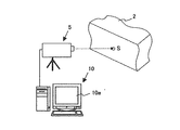
図1に示すように、ひずみ計測システムは、被測定物2の表面の計測対象領域Sを撮像する撮像装置5と、この撮像装置5により撮像された画像データに基づいて計測対象領域Sに発生するひずみを解析する解析装置10と、を備えている。
As shown in FIG. 1, the strain measurement system is generated in the measurement target region S based on the imaging device 5 that images the measurement target region S on the surface of the DUT 2 and the image data captured by the imaging device 5. And an
撮影装置5は、例えば、ディジタルビデオカメラなどの光学式撮像装置を用い、被測定物2の表面(計測対象領域)を撮像する。なお、撮影装置5は、当該ディジタルビデオカメラに限られるものではなく、CCDカメラ、デジタルカメラ、又はスキャナー等を適宜用いることが可能である。 The imaging device 5 uses an optical imaging device such as a digital video camera, for example, to image the surface (measurement target region) of the object 2 to be measured. Note that the photographing device 5 is not limited to the digital video camera, and a CCD camera, a digital camera, a scanner, or the like can be used as appropriate.
図1及び図2に示すように、解析装置10は、一般にコンピュータと称される装置であって表示画面10aを有している。この解析装置10は、撮像装置5によって撮像された画像データが入力されるI/F部12と、当該画像データを記憶する記憶部14と、当該画像データを画像解析する画像解析部15、画像解析によって得られたひずみ分布、及び応力を表示画面10a上に出力する出力部17と、制御部19と、を備えている。
As shown in FIGS. 1 and 2, the
制御部19は、演算機能を有するCPU(Central Processing Unit)、作業用RAM、不揮発性メモリ、及び各種処理プログラムやデータを記憶するROM等を備えている。そして、CPUが、ROMに記憶された各種処理プログラムを読み出し実行することにより、各部12、14、15、17を統括制御するようになっている。
The
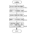
次に、ひずみ計測システムを用いて、被測定物2に発生するひずみや応力を計測する方法について図3を参照して説明する。 Next, a method for measuring strain and stress generated in the DUT 2 using the strain measurement system will be described with reference to FIG.
まず、被測定物2の表面において計測対象領域Sが使用者等によって設定され、当該計測対象領域Sが撮像可能になるように撮像装置5が固定される。そして、当該撮像装置5によって初期の状態(自重又は荷重による被測定物2の変位前)での計測対象領域Sが撮像される(ステップS11)。当該撮像された画像データは、I/F部12を介して記憶部14に記憶される(ステップS12)。
First, the measurement target area S is set by the user or the like on the surface of the DUT 2, and the imaging device 5 is fixed so that the measurement target area S can be imaged. And the measurement object area | region S in an initial state (Before displacement of the to-be-measured object 2 by dead weight or a load) is imaged by the said imaging device 5 (step S11). The captured image data is stored in the
次に、所定期間経過後(自重又は荷重による被測定物2の変位後)、撮像装置5によって当該計測対象領域Sが撮像される(ステップS13)。当該撮像された画像データは、I/F部12を介して記憶部14に記憶される(ステップS14)。
Next, after the elapse of a predetermined period (after displacement of the DUT 2 due to its own weight or load), the measurement target region S is imaged by the imaging device 5 (step S13). The captured image data is stored in the
次に、画像解析部15は、変位前の画像データと変位後の画像データを記憶部14から読み出して、所定の画像解析法に基づく解析を行う(ステップS15)。
Next, the
当該画像解析法としては、デジタル画像相関法が用いられる。2枚の画像を利用して変位量と移動方向を求める画像解析方法は数多く存在するため、その詳しい説明は省略する。 As the image analysis method, a digital image correlation method is used. Since there are many image analysis methods for obtaining the displacement amount and the moving direction using two images, detailed description thereof is omitted.
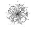
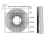
本実施形態では、図4に示すように、変位前後の画像データをもとに、例えば、ユーザによって計測対象領域Sの中心を基点Xとし、その基点を中心とした複数の同心円上に指標点が設定される。当該指標点は、例えば、基点Xを中心として円周方向に64分割した基準線Lと、複数の同心円とが交差するそれぞれの点に設定される。 In the present embodiment, as shown in FIG. 4, based on the image data before and after displacement, for example, the center of the measurement target region S is set as a base point X by the user, and index points are arranged on a plurality of concentric circles centered on the base point. Is set. The index point is set, for example, at each point where the reference line L divided into 64 in the circumferential direction around the base point X intersects with a plurality of concentric circles.
そして、画像解析部15は、変位前後の画像データから基点Xとそれぞれの指標点の2点間(半径方向)の距離変化を求め、その距離変化を基点Xとそれぞれの指標点間の距離で除算することによって、基点Xから各指標点方向(半径方向)のひずみを算出する。
Then, the
なお、変位前後の画像データから基点Xを点対称とする指標点の2点間(直径方向)の距離変化を求め、その距離変化を指標点間の距離で除算することによって、基点Xを点対称とする2点の指標点方向(直径方向)のひずみを算出するようにしても構わない。 It should be noted that a change in distance between two index points (diameter direction) that is symmetrical with respect to the base point X is obtained from the image data before and after displacement, and the base point X is determined by dividing the distance change by the distance between the index points. You may make it calculate the distortion | strain of 2 index point directions (diameter direction) made symmetrical.
当該画像解析部15は、算出されたひずみをもとに基点X周辺のひずみ分布を作成し、当該ひずみ分布を出力部17にて表示画面10a上に出力させる。
The
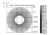
図5はひずみ分布の表示例を示す。この表示例は、直方体状に形成されたコンクリートに所定の垂直荷重を加えた時の一例を示すものであるが、ユーザは、基点Xを中心とするX方向には伸びる力が作用し、Y方向には縮む力が作用し、XY方向には力が作用していないことが容易にわかり、コンクリートの現状の応力状態を評価する上で有効である。 FIG. 5 shows a display example of the strain distribution. This display example shows an example when a predetermined vertical load is applied to the concrete formed in a rectangular parallelepiped shape. However, the user acts to extend in the X direction around the base point X, and Y It is easy to understand that a shrinking force acts in the direction and no force acts in the XY direction, which is effective in evaluating the current stress state of concrete.
このようにして、基点を中心とする半径方向の指標点の2点、又は基点を点対称とする指標点の2点の距離変化に基づいて所定方向のひずみを算出し、当該算出したひずみをもとに基点周辺のひずみ分布を出力すれば、変位量が小さい場合であっても精度の高いひずみの計測が可能である。また、当該ひずみ分布によって基点周辺のひずみの発生状況を容易に把握可能であり、例えば、異常値が検出されれば、その指標点付近でクラックが生じているなどの状況がわかる。また、同一個所における複数のひずみ計測が可能となり、被測定物2に発生するひずみを面的に把握することが容易に可能となる。 In this way, the strain in a predetermined direction is calculated based on the distance change between the two index points in the radial direction centered on the base point or the two index points that are point-symmetric with respect to the base point. Basically, if the strain distribution around the base point is output, it is possible to measure the strain with high accuracy even when the displacement is small. Further, the strain distribution around the base point can be easily grasped by the strain distribution. For example, if an abnormal value is detected, it is possible to know a situation such as a crack near the index point. In addition, a plurality of strain measurements can be performed at the same location, and the strain generated in the DUT 2 can be easily grasped in a plane.
また、画像解析部15は、被測定物2に発生する応力を算出する。応力は、基点をもとに平面ひずみ状態が解析できるロゼット解析のための3軸又は4軸方向のひずみの組み合わせを抽出して算出される。一般に、ロゼット解析で用いられるロゼットの種類として、基点をもとに120°又は45°の角度をなす3軸方向のひずみから応力を算出する等角三軸型、又は直角三軸型の三方向測定ロゼットや基点をもとに45°の角度をなす4軸方向のひずみから応力を算出する二重直角四軸型、又はTデルタ四軸型の四方向測定ロゼットと称される方式が知られている。
Further, the
以下に直角三軸型における応力算出方法を一例として説明する。 The stress calculation method in the right-angle triaxial type will be described below as an example.
例えば、図6に示すように、同一点を基点としてx方向、y方向、及びx方向とy方向と45度の角度をなすxy方向の3軸方向のひずみa〜cが求まれば、被測定物における最大(最小)主応力は、次式(式1)から求まることが従来から知られている。 For example, as shown in FIG. 6, if strains a to c in the x-axis direction, the y-direction, and the x-direction and the xy-direction that form an angle of 45 degrees with the y-direction from the same point are obtained, It has been conventionally known that the maximum (minimum) principal stress in a measured object is obtained from the following equation (Equation 1).
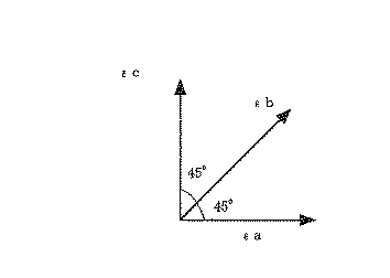
すなわち、本実施形態では、同一の基点から上記3軸方向のひずみの組み合わせを複数抽出し、それぞれの組み合わせによって求められる応力を算出後、それらの平均が算出される。これにより、同一基点から多数のひずみ解析結果を得られるため、高精度のひずみ計測が可能となる。 That is, in the present embodiment, a plurality of combinations of the strains in the three axial directions are extracted from the same base point, and after calculating the stress obtained by each combination, an average of them is calculated. Thereby, since many strain analysis results can be obtained from the same base point, highly accurate strain measurement is possible.
具体的には、例えば、図4では基点Xを中心として円周方向に64分割された線Lと複数の同心円のそれぞれが交差している点に指標点が配置されているため、複数の同心円のうち1の円において、基点Xから半径方向での異なる3軸方向の組み合わせが64組抽出可能となっている。よって、画像解析部15は、64組の組み合わせからなる3軸方向のひずみをもとに応力を算出後、それらの平均を算出する。
Specifically, for example, in FIG. 4, the index point is arranged at a point where the line L divided into 64 in the circumferential direction around the base point X intersects each of the plurality of concentric circles. In one of the circles, it is possible to extract 64 combinations of different triaxial directions from the base point X in the radial direction. Therefore, the
しかしながら、必ずしも64組のそれぞれの組み合わせにおける主応力の平均を算出すべき必要はなく、そのいくつかの組み合わせをランダムに抽出して、その組み合わせにおける応力の平均を算出するようにしても構わない。 However, it is not always necessary to calculate the average of the principal stresses in each of the 64 combinations, and some combinations may be extracted at random to calculate the average of the stresses in the combinations.
なお、上記実施形態では、基点Xから半径方向での異なる3軸方向の組み合わせを抽出しているが、基点Xを点対称とする直径方向での異なる3軸方向の組み合わせを抽出するようにしても構わない。その場合には、上記実施形態では、異なる3軸方向の組み合わせが32組抽出可能となる。 In the above embodiment, combinations of different triaxial directions in the radial direction are extracted from the base point X. However, different combinations of triaxial directions in the diameter direction with the base point X being point-symmetric are extracted. It doesn't matter. In that case, in the above-described embodiment, 32 combinations of different three-axis directions can be extracted.
ここで、ひずみの計測精度を検証するために、幅370mm、奥行き240mm、高さ470mmの直方体に形成された不均一材料であるコンクリートを試験体として、鉛直荷重(P=1335kN)を加えた時に生じる応力をひずみ計測システムを用いて解析した。なお、解析結果を図5に示す。 Here, in order to verify the measurement accuracy of the strain, when a vertical load (P = 1335 kN) was applied using a concrete, which is a non-uniform material formed in a rectangular parallelepiped having a width of 370 mm, a depth of 240 mm, and a height of 470 mm, as a test body The resulting stress was analyzed using a strain measurement system. The analysis results are shown in FIG.
図5に示す解析結果をもとに、3軸方向のひずみの組み合わせをランダムに16組抽出してひずみの解析を行い、主応力の平均値を算出した結果、最大主応力σ1は、15.75N/mm2であった。 Based on the analysis result shown in FIG. 5, 16 combinations of strains in the triaxial direction are extracted at random and the strain is analyzed. As a result of calculating the average value of the principal stress, the maximum principal stress σ1 is 15. It was 75 N / mm 2 .
一方、一般的な計算式で主応力を算出すると、σ1’=載荷荷重/断面積より、15.03N/mm2であるから、解析結果と計算値とはほぼ一致し、その精度が高いことが確認できた。 On the other hand, if the principal stress is calculated by a general calculation formula, σ1 ′ = loaded load / cross-sectional area is 15.03 N / mm 2 , so the analysis result and the calculated value are almost the same, and the accuracy is high. Was confirmed.
ひずみゲージで計測すると、その計測位置によって非常に大きな誤差を持つバラツキが生じるなどの不具合が発生するものの、本願発明によるひずみ解析では精度を高めることが容易に可能である。 When measuring with a strain gauge, problems such as variations with very large errors occur depending on the measurement position, but the strain analysis according to the present invention can easily increase the accuracy.
また、応力開放実験のように局所的な変形や測定物の形状によって基点Xから円周方向に離れて設定されている指標点は、変形の影響を受けない。これらの場合では変形の影響を受けない不動点が設定できるため、その不動点が含まれるように計測対象領域を広げ、変位前後の画像データから当該不動点の移動状態(移動方向及び移動量)を求め、ひずみ解析を行なう際に当該不動点の移動状態を参照して補正することで、撮像装置が何らかの要因により移動した場合などの影響を除去することが可能となりひずみ計測の精度をより高めることが可能となる。具体的には、変位前後の画像データ中の不動点が移動した場合には、変位後の画像データに対して、その不動点の移動量及び方向を補正すれば良い。また、測定物の変形の影響を受けない不動点を変位前後で同時に解析画像上に取り込むことで任意に不動点を作ることも可能である。 In addition, the index point set away from the base point X in the circumferential direction due to local deformation or the shape of the measurement object as in the stress release experiment is not affected by the deformation. In these cases, a fixed point that is not affected by deformation can be set, so the measurement target area is expanded so that the fixed point is included, and the movement state (moving direction and moving amount) of the fixed point from the image data before and after the displacement. When the strain analysis is performed, the movement state of the fixed point is referred to and corrected, so that the influence of the imaging device moving due to some factor can be removed and the accuracy of strain measurement is further improved. It becomes possible. Specifically, when the fixed point in the image data before and after the displacement moves, the moving amount and direction of the fixed point may be corrected for the image data after the displacement. It is also possible to arbitrarily create a fixed point by capturing a fixed point that is not affected by the deformation of the measurement object on the analysis image before and after the displacement.
また、他の実施形態として、図5で用いた試験体に鉛直荷重(P=1335KN)を作用させた状態で、直径50mmの円孔(深さ50mm)を設けて試験体の側面中心部付近を応力開放し、応力開放前後のひずみ変化の状態を解析し、その結果を図7に示す。なお、この時の解析を行った指標点は円孔外周近傍から外側に規定し、応力開放前後の基点から各指標点方向のひずみを上記に示す実施形態と同様に算出し、ひずみ分布を出力したものである。 As another embodiment, in the state where a vertical load (P = 1335KN) is applied to the test body used in FIG. 5, a circular hole having a diameter of 50 mm (depth of 50 mm) is provided and near the center of the side surface of the test body. The stress is released, the state of strain change before and after the stress release is analyzed, and the result is shown in FIG. The index points analyzed at this time are defined from the vicinity of the outer circumference of the hole to the outside, the strain in the direction of each index point is calculated from the base point before and after stress release in the same manner as in the above embodiment, and the strain distribution is output. It is a thing.
図7に示す解析結果(ひずみ分布図)からも明らかなように、円孔近傍で鉛直方向への縮み状態、水平方向の伸びの状態、基点を中心として45°で伸びる方向が無ひずみの状態であることが確認できた。この結果より、被測定体の端部が円形の場合であってもひずみ分布を容易に解析することができることが確認できた。なお、応力を求める場合には、ひずみ分布の変化量をFEM解析などにより逆算することで容易に求めることが可能である。 As is clear from the analysis result (strain distribution diagram) shown in FIG. 7, the state of contraction in the vertical direction in the vicinity of the circular hole, the state of elongation in the horizontal direction, and the state of no strain in the direction extending at 45 ° around the base point It was confirmed that. From this result, it was confirmed that the strain distribution can be easily analyzed even when the end of the object to be measured is circular. In addition, when calculating | requiring stress, it is possible to calculate | require easily by calculating back the variation | change_quantity of strain distribution by FEM analysis etc.
なお、本願発明は、コンクリートなどの材料で計測対象点のひずみ計測にばらつきが生じ易い場合や計測対象物が凹凸形状、又は柔らかい材料であるためにひずみゲージを取り付けにくい場合、計測対象物が微小であるためにひずみゲージを取り付けにくい場合、ひずみ変化が大きい部分のひずみ分布を緻密に計測したい場合などの特に有効である。 In the present invention, if the strain measurement of a measurement target point is likely to vary with a material such as concrete, or if the measurement target is an uneven shape or a soft material, it is difficult to attach a strain gauge. Therefore, it is particularly effective when it is difficult to attach a strain gauge or when it is desired to precisely measure the strain distribution in a portion where the strain change is large.
また、本実施形態は一形態であって、この形態に限定されるものではない。 Moreover, this embodiment is one form and is not limited to this form.
S 計測対象領域
2 被測定物
5 光学式計測装置
10 解析装置
S measurement object region 2 object to be measured 5
Claims (7)
変形前後の画像データから前記基点とそれぞれの指標点の2点間の距離変化を求めて前記基点から各指標点方向のひずみを算出し、その算出結果に基づいて前記基点周辺のひずみ分布を解析する解析工程と、
を備えていることを特徴とするひずみ計測方法。 An arbitrary base point on the object to be measured, and a plurality of index points on a plurality of concentric circles centered on the base point, and the surface before and after the deformation of the object to be measured is optical so that the base point and the index points are included. An image data acquisition step of imaging with an imaging device and acquiring image data before and after the deformation;
The distance between the base point and each index point is calculated from the image data before and after the deformation, the strain in the direction of each index point is calculated from the base point, and the strain distribution around the base point is analyzed based on the calculation result Analysis process to
A strain measuring method characterized by comprising:
変形前後の画像データから前記基点を点対称とする指標点の2点間の距離変化を求めて前記基点から各指標点方向のひずみを算出し、その算出結果に基づいて前記基点周辺のひずみ分布を解析する解析工程と、
を備えていることを特徴とするひずみ計測方法。 An arbitrary base point on the object to be measured, and a plurality of index points on a plurality of concentric circles centered on the base point, and the surface before and after the deformation of the object to be measured is optical so that the base point and the index points are included. An image data acquisition step of imaging with an imaging device and acquiring image data before and after the deformation;
From the image data before and after the deformation, a change in the distance between two index points that are symmetrical with respect to the base point is calculated, strains in the direction of the respective index points are calculated from the base point, and strain distribution around the base point is calculated based on the calculation result An analysis process for analyzing
A strain measuring method characterized by comprising:
変形前後の画像データから前記基点とそれぞれの指標点の2点間の距離変化を求めて前記基点から各指標点方向のひずみを算出し、その算出結果に基づいて前記基点周辺のひずみ分布を解析する解析手段と、
を備えていることを特徴とするひずみ計測システム。 An arbitrary base point on the object to be measured, and a plurality of index points on a plurality of concentric circles centered on the base point, and the surface before and after the deformation of the object to be measured is optical so that the base point and the index points are included. Image data acquisition means for acquiring an image data before and after being imaged by an imaging device;
The distance between the base point and each index point is calculated from the image data before and after the deformation, the strain in the direction of each index point is calculated from the base point, and the strain distribution around the base point is analyzed based on the calculation result Analysis means to
A strain measurement system comprising:
変形前後の画像データから前記基点を点対称とする指標点の2点間の距離変化を求めて前記基点から各指標点方向のひずみを算出し、その算出結果に基づいて前記基点周辺のひずみ分布を解析する解析手段と、
を備えていることを特徴とするひずみ計測システム。 An arbitrary base point on the object to be measured, and a plurality of index points on a plurality of concentric circles centered on the base point, and the surface before and after the deformation of the object to be measured is optical so that the base point and the index points are included. Image data acquisition means for acquiring an image data before and after being imaged by an imaging device;
From the image data before and after the deformation, a change in the distance between two index points that are symmetrical with respect to the base point is calculated, strains in the direction of the respective index points are calculated from the base point, and strain distribution around the base point is calculated based on the calculation result An analysis means for analyzing
A strain measurement system comprising:
Priority Applications (1)
| Application Number | Priority Date | Filing Date | Title |
|---|---|---|---|
| JP2008084560A JP5343219B2 (en) | 2008-03-27 | 2008-03-27 | Strain measurement method, strain measurement system |
Applications Claiming Priority (1)
| Application Number | Priority Date | Filing Date | Title |
|---|---|---|---|
| JP2008084560A JP5343219B2 (en) | 2008-03-27 | 2008-03-27 | Strain measurement method, strain measurement system |
Publications (2)
| Publication Number | Publication Date |
|---|---|
| JP2009236754A true JP2009236754A (en) | 2009-10-15 |
| JP5343219B2 JP5343219B2 (en) | 2013-11-13 |
Family
ID=41250883
Family Applications (1)
| Application Number | Title | Priority Date | Filing Date |
|---|---|---|---|
| JP2008084560A Active JP5343219B2 (en) | 2008-03-27 | 2008-03-27 | Strain measurement method, strain measurement system |
Country Status (1)
| Country | Link |
|---|---|
| JP (1) | JP5343219B2 (en) |
Cited By (10)
| Publication number | Priority date | Publication date | Assignee | Title |
|---|---|---|---|---|
| JP2012136089A (en) * | 2010-12-24 | 2012-07-19 | Sumitomo Rubber Ind Ltd | Measuring method of sidewall surface strain of tire |
| JP2012163346A (en) * | 2011-02-03 | 2012-08-30 | Univ Of Miyazaki | Apparatus and method for measuring surface shape |
| JP2016136108A (en) * | 2015-01-23 | 2016-07-28 | 住友ゴム工業株式会社 | Rigidity measurement method of side wall of tyre |
| JP2017096935A (en) * | 2015-11-16 | 2017-06-01 | ゼネラル・エレクトリック・カンパニイ | Methods for monitoring components |
| JP2018017620A (en) * | 2016-07-28 | 2018-02-01 | 公益財団法人鉄道総合技術研究所 | State change detection apparatus, and state change detection program |
| KR20180030818A (en) * | 2018-03-16 | 2018-03-26 | 충남대학교산학협력단 | Evaluating Method of Strain Using Void Deformation |
| KR101841202B1 (en) | 2015-06-24 | 2018-05-04 | 충남대학교산학협력단 | Evaluating Method of Strain Using Void Deformation, Deflection Measurement Method and Stress Measurement Method Using the Same |
| CN112752963A (en) * | 2019-08-29 | 2021-05-04 | 汤浅系统机器株式会社 | Deformation testing machine |
| EP3182059B1 (en) * | 2015-12-17 | 2022-02-16 | General Electric Company | Method for strain monitoring turbine components |
| CN115540818A (en) * | 2022-12-02 | 2022-12-30 | 北京建工集团有限责任公司 | Underground space elevation measurement method for transmitting base point elevation through member |
Citations (14)
| Publication number | Priority date | Publication date | Assignee | Title |
|---|---|---|---|---|
| JPS62293133A (en) * | 1986-06-12 | 1987-12-19 | Tokai Rika Co Ltd | Mirror distortion measuring instrument |
| JPH04500408A (en) * | 1989-02-27 | 1992-01-23 | カムシス・インコーポレーテッド | Computerized method for measuring strain distribution on the surface of a deformed body |
| JPH05288510A (en) * | 1992-04-07 | 1993-11-02 | Nippon Telegr & Teleph Corp <Ntt> | Measuring method for chip dislocation |
| JPH0783624A (en) * | 1993-09-10 | 1995-03-28 | Idemitsu Material Kk | Measurement method and device for strain of molding stamper |
| JPH09175457A (en) * | 1995-12-27 | 1997-07-08 | Tokai Rika Co Ltd | Distortion inspection method and distortion inspection device |
| JPH09222313A (en) * | 1996-02-19 | 1997-08-26 | Mitsubishi Automob Eng Co Ltd | Method and device for measuring distortion of mirror surface with gradually changing curvature of complex curved-surface mirror |
| JPH1183439A (en) * | 1997-09-04 | 1999-03-26 | Nikon Corp | Image measurement device |
| JP2001105485A (en) * | 1999-10-12 | 2001-04-17 | Sumitomo Chem Co Ltd | Method for measuring distortion rate generated by thermoforming |
| JP2003232688A (en) * | 2002-02-08 | 2003-08-22 | Japan Science & Technology Corp | Two-dimensional stress field measuring system and two- dimensional stress field measuring program |
| JP2004328096A (en) * | 2003-04-22 | 2004-11-18 | Sony Corp | Image processing apparatus and method, recording medium, and program |
| JP2005351760A (en) * | 2004-06-10 | 2005-12-22 | Honda Lock Mfg Co Ltd | Distortion measuring method and system |
| WO2007000323A1 (en) * | 2005-06-29 | 2007-01-04 | Hottinger Baldwin Messtechnik Gmbh | Optical strain gauge strips |
| JP2007003380A (en) * | 2005-06-24 | 2007-01-11 | Taisei Corp | Object monitoring system, object monitoring method, and object monitoring program |
| JP2007131304A (en) * | 2005-11-08 | 2007-05-31 | Sekisui Plastics Co Ltd | Foamed sheet container having print, and food package |
-
2008
- 2008-03-27 JP JP2008084560A patent/JP5343219B2/en active Active
Patent Citations (14)
| Publication number | Priority date | Publication date | Assignee | Title |
|---|---|---|---|---|
| JPS62293133A (en) * | 1986-06-12 | 1987-12-19 | Tokai Rika Co Ltd | Mirror distortion measuring instrument |
| JPH04500408A (en) * | 1989-02-27 | 1992-01-23 | カムシス・インコーポレーテッド | Computerized method for measuring strain distribution on the surface of a deformed body |
| JPH05288510A (en) * | 1992-04-07 | 1993-11-02 | Nippon Telegr & Teleph Corp <Ntt> | Measuring method for chip dislocation |
| JPH0783624A (en) * | 1993-09-10 | 1995-03-28 | Idemitsu Material Kk | Measurement method and device for strain of molding stamper |
| JPH09175457A (en) * | 1995-12-27 | 1997-07-08 | Tokai Rika Co Ltd | Distortion inspection method and distortion inspection device |
| JPH09222313A (en) * | 1996-02-19 | 1997-08-26 | Mitsubishi Automob Eng Co Ltd | Method and device for measuring distortion of mirror surface with gradually changing curvature of complex curved-surface mirror |
| JPH1183439A (en) * | 1997-09-04 | 1999-03-26 | Nikon Corp | Image measurement device |
| JP2001105485A (en) * | 1999-10-12 | 2001-04-17 | Sumitomo Chem Co Ltd | Method for measuring distortion rate generated by thermoforming |
| JP2003232688A (en) * | 2002-02-08 | 2003-08-22 | Japan Science & Technology Corp | Two-dimensional stress field measuring system and two- dimensional stress field measuring program |
| JP2004328096A (en) * | 2003-04-22 | 2004-11-18 | Sony Corp | Image processing apparatus and method, recording medium, and program |
| JP2005351760A (en) * | 2004-06-10 | 2005-12-22 | Honda Lock Mfg Co Ltd | Distortion measuring method and system |
| JP2007003380A (en) * | 2005-06-24 | 2007-01-11 | Taisei Corp | Object monitoring system, object monitoring method, and object monitoring program |
| WO2007000323A1 (en) * | 2005-06-29 | 2007-01-04 | Hottinger Baldwin Messtechnik Gmbh | Optical strain gauge strips |
| JP2007131304A (en) * | 2005-11-08 | 2007-05-31 | Sekisui Plastics Co Ltd | Foamed sheet container having print, and food package |
Cited By (12)
| Publication number | Priority date | Publication date | Assignee | Title |
|---|---|---|---|---|
| JP2012136089A (en) * | 2010-12-24 | 2012-07-19 | Sumitomo Rubber Ind Ltd | Measuring method of sidewall surface strain of tire |
| JP2012163346A (en) * | 2011-02-03 | 2012-08-30 | Univ Of Miyazaki | Apparatus and method for measuring surface shape |
| JP2016136108A (en) * | 2015-01-23 | 2016-07-28 | 住友ゴム工業株式会社 | Rigidity measurement method of side wall of tyre |
| KR101841202B1 (en) | 2015-06-24 | 2018-05-04 | 충남대학교산학협력단 | Evaluating Method of Strain Using Void Deformation, Deflection Measurement Method and Stress Measurement Method Using the Same |
| JP2017096935A (en) * | 2015-11-16 | 2017-06-01 | ゼネラル・エレクトリック・カンパニイ | Methods for monitoring components |
| EP3182059B1 (en) * | 2015-12-17 | 2022-02-16 | General Electric Company | Method for strain monitoring turbine components |
| JP2018017620A (en) * | 2016-07-28 | 2018-02-01 | 公益財団法人鉄道総合技術研究所 | State change detection apparatus, and state change detection program |
| KR20180030818A (en) * | 2018-03-16 | 2018-03-26 | 충남대학교산학협력단 | Evaluating Method of Strain Using Void Deformation |
| KR102215032B1 (en) | 2018-03-16 | 2021-02-10 | 충남대학교산학협력단 | Evaluating Method of Strain Using Void Deformation |
| CN112752963A (en) * | 2019-08-29 | 2021-05-04 | 汤浅系统机器株式会社 | Deformation testing machine |
| CN115540818A (en) * | 2022-12-02 | 2022-12-30 | 北京建工集团有限责任公司 | Underground space elevation measurement method for transmitting base point elevation through member |
| CN115540818B (en) * | 2022-12-02 | 2023-03-24 | 北京建工集团有限责任公司 | Underground space elevation measurement method for transmitting base point elevation through member |
Also Published As
| Publication number | Publication date |
|---|---|
| JP5343219B2 (en) | 2013-11-13 |
Similar Documents
| Publication | Publication Date | Title |
|---|---|---|
| JP5343219B2 (en) | Strain measurement method, strain measurement system | |
| JP4811567B2 (en) | Stress measurement method for structures using photographed images | |
| Genovese et al. | A 360-deg digital image correlation system for materials testing | |
| CN109342189B (en) | Tension-torsion combined multi-axis fracture experiment system and experiment method | |
| US9903781B2 (en) | Material testing apparatus and method | |
| KR101163916B1 (en) | A mesuring method for stress-strain curve and a apparatus for the same | |
| JP6240206B2 (en) | Displacement field and strain field measurement method and material testing machine | |
| JP2012021958A5 (en) | ||
| KR102218594B1 (en) | Device and Method for measuring material properties and stress state by digital image correlation(DIC) near micro-indentation mark | |
| JP2007078659A (en) | Method and device for determining analysis condition of digital image correlation method | |
| JP2017090071A (en) | Hardness tester and hardness testing method | |
| Poozesh et al. | Full field inspection of a utility scale wind turbine blade using digital image correlation | |
| JP2007303916A (en) | Method for measuring stress of structure | |
| Dahl et al. | Planar strain measurements on wood specimens | |
| JPWO2008146532A1 (en) | Stress measuring method for structure, strain measuring method and system for object to be measured | |
| JP2017036978A (en) | Stress measurement device and stress measurement method | |
| JP2019011995A (en) | Rigidity measuring device, rigidity measuring method, and program | |
| JP2003232688A (en) | Two-dimensional stress field measuring system and two- dimensional stress field measuring program | |
| JP6248706B2 (en) | Stress distribution measuring apparatus and stress distribution measuring method | |
| JP2020193820A5 (en) | ||
| Moser et al. | 3d digital imaging correlation: Applications to tire testing | |
| JP2001056272A (en) | Measuring method of stress enlarging factor | |
| KR101475742B1 (en) | Apparatus and method for performing photogrammetry | |
| JP2008209313A (en) | Distortion measuring method, or the like | |
| Le Blanc et al. | Image correlation applied to single crystal plasticity experiments and comparison to strain gage data |
Legal Events
| Date | Code | Title | Description |
|---|---|---|---|
| A621 | Written request for application examination |
Free format text: JAPANESE INTERMEDIATE CODE: A621 Effective date: 20110324 |
|
| A521 | Request for written amendment filed |
Free format text: JAPANESE INTERMEDIATE CODE: A523 Effective date: 20110506 |
|
| A977 | Report on retrieval |
Free format text: JAPANESE INTERMEDIATE CODE: A971007 Effective date: 20120719 |
|
| A131 | Notification of reasons for refusal |
Free format text: JAPANESE INTERMEDIATE CODE: A131 Effective date: 20120814 |
|
| A521 | Request for written amendment filed |
Free format text: JAPANESE INTERMEDIATE CODE: A523 Effective date: 20121015 |
|
| TRDD | Decision of grant or rejection written | ||
| A01 | Written decision to grant a patent or to grant a registration (utility model) |
Free format text: JAPANESE INTERMEDIATE CODE: A01 Effective date: 20130618 |
|
| A61 | First payment of annual fees (during grant procedure) |
Free format text: JAPANESE INTERMEDIATE CODE: A61 Effective date: 20130716 |
|
| R150 | Certificate of patent or registration of utility model |
Ref document number: 5343219 Country of ref document: JP Free format text: JAPANESE INTERMEDIATE CODE: R150 Free format text: JAPANESE INTERMEDIATE CODE: R150 |
|
| R250 | Receipt of annual fees |
Free format text: JAPANESE INTERMEDIATE CODE: R250 |
|
| R250 | Receipt of annual fees |
Free format text: JAPANESE INTERMEDIATE CODE: R250 |
|
| R250 | Receipt of annual fees |
Free format text: JAPANESE INTERMEDIATE CODE: R250 |
|
| R250 | Receipt of annual fees |
Free format text: JAPANESE INTERMEDIATE CODE: R250 |
|
| R250 | Receipt of annual fees |
Free format text: JAPANESE INTERMEDIATE CODE: R250 |
|
| R250 | Receipt of annual fees |
Free format text: JAPANESE INTERMEDIATE CODE: R250 |
|
| S111 | Request for change of ownership or part of ownership |
Free format text: JAPANESE INTERMEDIATE CODE: R313117 |
|
| S531 | Written request for registration of change of domicile |
Free format text: JAPANESE INTERMEDIATE CODE: R313531 |
|
| R350 | Written notification of registration of transfer |
Free format text: JAPANESE INTERMEDIATE CODE: R350 |
|
| R250 | Receipt of annual fees |
Free format text: JAPANESE INTERMEDIATE CODE: R250 |
|
| R250 | Receipt of annual fees |
Free format text: JAPANESE INTERMEDIATE CODE: R250 |